EP1560970B1 - Accessoire programmable de plissage pour machine a coudre et procede - Google Patents
Accessoire programmable de plissage pour machine a coudre et procede Download PDFInfo
- Publication number
- EP1560970B1 EP1560970B1 EP03776289A EP03776289A EP1560970B1 EP 1560970 B1 EP1560970 B1 EP 1560970B1 EP 03776289 A EP03776289 A EP 03776289A EP 03776289 A EP03776289 A EP 03776289A EP 1560970 B1 EP1560970 B1 EP 1560970B1
- Authority
- EP
- European Patent Office
- Prior art keywords
- tucking
- sewing machine
- border
- sewing
- upper decking
- Prior art date
- Legal status (The legal status is an assumption and is not a legal conclusion. Google has not performed a legal analysis and makes no representation as to the accuracy of the status listed.)
- Expired - Lifetime
Links
Images




Classifications
-
- D—TEXTILES; PAPER
- D05—SEWING; EMBROIDERING; TUFTING
- D05B—SEWING
- D05B35/00—Work-feeding or -handling elements not otherwise provided for
- D05B35/08—Work-feeding or -handling elements not otherwise provided for for ruching, gathering, casing, or filling lace, ribbons, or bindings; Pleating devices; Cuttlers; Gathering feet; Crimpers; Curlers; Rufflers
- D05B35/085—Work-feeding or -handling elements not otherwise provided for for ruching, gathering, casing, or filling lace, ribbons, or bindings; Pleating devices; Cuttlers; Gathering feet; Crimpers; Curlers; Rufflers for making folds transversely to the sewing direction
-
- D—TEXTILES; PAPER
- D05—SEWING; EMBROIDERING; TUFTING
- D05B—SEWING
- D05B11/00—Machines for sewing quilts or mattresses
- D05B11/005—Machines for sewing quilts or mattresses for sewing the edges of mattresses
-
- D—TEXTILES; PAPER
- D05—SEWING; EMBROIDERING; TUFTING
- D05B—SEWING
- D05B19/00—Program-controlled sewing machines
- D05B19/02—Sewing machines having electronic memory or microprocessor control unit
- D05B19/12—Sewing machines having electronic memory or microprocessor control unit characterised by control of operation of machine
-
- D—TEXTILES; PAPER
- D10—INDEXING SCHEME ASSOCIATED WITH SUBLASSES OF SECTION D, RELATING TO TEXTILES
- D10B—INDEXING SCHEME ASSOCIATED WITH SUBLASSES OF SECTION D, RELATING TO TEXTILES
- D10B2505/00—Industrial
- D10B2505/08—Upholstery, mattresses
Definitions
- This invention relates generally to tucking fabric in a sewing process and more particularly, to a method for tucking fabric in the process of sewing mattresses.
- a single machine for making the gusset and for attaching the flange material.
- This machine folds the gusset, stitches it together in its folded condition, and secures the flange material to the gusset.
- the finished gusset is then cut into lengths and bound to a mattress panel.
- a mitering station is provided closely adjacent the binding machine.
- the binding machine is stopped, and the operator measures exactly the distance from that point to the corner of the panel. An equivalent distance is marked on the gusset material. The operator then pulls that part of the gusset material over to the closely adjacent mitering station.
- the gusset material is first folded transversely at that point.
- two stitches are applied by a sewing machine to the gusset from the folded edge inwardly.
- Each stitch is at a 45 degree angle with respect to the folded edge of the gusset, so that the stitches form a 90 degree angle with respect to each other.
- the sewing machine preferably is preprogrammed to stitch precisely the desired number of stitches needed for the miter. All the operator must do is wait until the stitches have completed, rotate the gusset material through 90 degrees and start the machine again. Thereafter, the triangular section defined by the stitches and the folded edge is cut out of the gusset material either automatically, or manually, and the gusset material is removed from the mitering station. While more automated, the above operation still requires numerous steps by the operator to form a corner during the process of attaching the gusset to another piece.
- Another challenge in sewing bedding components at their respective corners arises when attaching an upper decking to a border of a bedding foundation, for example, a box spring.
- an edge of the upper decking material is sewn to an edge of the bedding foundation material along the outer edge of the bedding foundation.
- the joint between the corner of the upper decking can be precut so that there is no or minimal excess material at the corner. If the corners in the upper decking material are not precut, the machine operator must gather the material to accommodate the extra material at the corners. Unless the operator is particularly skilled, sometimes the result is a rather uneven look, since the bedding foundation components are unwieldy and difficult to maneuver around the corners. Further, since the sewn joint is at the edge of the bedding foundation, the upper decking material is often visible even after a mattress is set on top of the bedding foundation.
- the bedding foundation border material to the upper decking material at a location inside the outer edge of the bedding foundation, for example, 3-4 inches (7.60 - 10.16 cm) inside the bedding foundation edge.
- Mitering of the bedding foundation border material is accomplished by techniques similar to those described above. While improving the appearance of the finished bedding foundation, the additional labor required substantially increases the manufacturing cost of the bedding foundation.
- US 6202579 discloses a machine for automatically producing a mattress border with handles sewn to the border material.
- Border material is pre-fed from a selected spool, screened for splice avoidance and measured.
- Handle material is fed from a selected spool mounted in a multiple handle material spool magazine mounted on rails, fed into a handle folding assembly, and cut to length. Ends of the handle material are folded under by the handle folding assembly and the handle then transferred in a folded condition from the handle folding assembly to a correct position on the border material.
- a double frame handle press holds each folded end of the handle material in place as each end is manoeuvred under a sewing head needle to apply a stitch pattern to secure the folded ends to the border material.
- the double frame handle press is translated separately from the carriage assembly which travels in the sew patterns, to position the other end of the handle under the sewing needle.
- the present invention provides a method of sewing a first material supported on a base plate of a sewing machine to a second material as the second material is being tucked by a tucking attachment, the sewing machine having a presser foot for holding first and second materials and a reciprocating needle for sewing the first and second materials together, the method comprising:
- a tucking attachment for a sewing machine that facilitates sewing one material to another around a corner.
- the tucking attachment permits tucks of different lengths to be formed in a material. Therefore, the tucking attachment provides great flexibility in controlling the fullness of material in sewing around a corner as well as the appearance and style of the finished material. Further, with the tucking attachment, the formation of each tuck is automatically and precisely controlled; and therefore, the formation of tucks around a corner is repeatable from corner to corner.
- the tucking attachment automatically creates material tucks so that the material can be guided to sew a seam around a corner with a minimum of operator intervention; and therefore, high quality material corners can be sewn without substantially increasing the manufacturing costs.
- the tucking attachment is especially useful in joining components used to make a mattress or a bedding foundation.
- the capability of programming different lengths of successive tucks in sewing the corners of two components together permits a bedding manufacturer to create appearances that are different and unique to the manufacturer. Further, since operator intervention is not required in the formation of the individual material tucks, the operator can concentrate on overall material handling. The net result is a material tucking and sewing process that is more efficient and less stressful and tiring on the operator while producing a more consistent and higher quality product.
- the tucking attachment has a tucking blade with one end positioned adjacent the material and a tucking blade drive with an output shaft mechanically coupled to the tucking blade.
- a control connected to the tucking blade drive, has a memory storing programmable displacements of the tucking blade and is operable to command the tucking blade drive to move the tucking blade through a programmable displacement to form a tuck in the material adjacent a presser foot of the sewing machine. Thereafter, the control is operable to command the tucking blade drive to move the tucking blade in an opposite direction.
- the tucking blade and tucking blade drive are pivotally mounted to a support attached to the sewing machine, thereby allowing the tucking blade and tucking blade drive to be pivoted to an open position that allows more access to the sewing machine presser foot and needle.
- a method for forming a tuck in a stitchable material on a sewing machine having a presser foot for holding the material and a needle for sewing the material held by the presser foot.
- the material is located beneath the presser foot; and then, a tucking blade is moved into contact with the material of the presser foot. Thereafter, the tucking blade is moved through a programmable displacement toward the presser foot to form a tuck in the material below the presser foot.
- the sewing machine is then operated to sew a number of stitches through the tuck, the tucking blade is retracted. In one embodiment, that process is repeated until a desired number of tucks are formed.
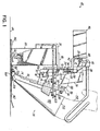
- a sewing system 20 has a sewing machine 22 mounted in a base plate 24 in a known manner.
- the sewing machine includes a presser foot 26 and a needle 28 that is reciprocated and carries a needle thread and a bobbin thread in a known manner.
- the sewing machine 22 is a commercial sewing machine that performs lock stitching. Lock stitching is a known technique of interlacing a needle thread and bobbin thread, which will not be further described here.
- a tucking attachment 30 is mounted on the sewing machine by means of mounting brackets 32, 110.
- the tucking attachment 30 of Fig. 1 includes a tucking blade 34 that is mounted in a tucking arm 36.
- the tucking arm 36 has an upper end 38 pivotally mounted to a pivot pin or trunnion 39 that is supported between a pair of opposed bearing blocks 41, 60( Fig. 2 ) that are mounted on a support bracket 42.
- a tucking blade drive 44 is also mounted to the support bracket 42 and is operative to provide a pivoting motion to the tucking arm 36, thereby causing the tucking blade 34 to form tucks in a material in a manner as will subsequently be described.
- the tucking blade drive 44 is powered by an actuator 46, for example, an AC servomotor.
- the servomotor 46 is connected to a generally U-shaped motor bracket 48.
- the motor bracket 48 has opposed legs 50, 52 that extend outward from the motor 46 in a direction generally parallel to a motor output shaft formed as a ball screw 54.
- the opposed legs 50, 52 are pivotally mounted on respective opposed pivot pins 56, 58 that, in turn, are supported by respective opposed support blocks 60, 62.
- a ball nut 64 is mounted on the ball screw 54 and is pivotally mounted on opposed pivot pins 65 supported by a clevis 66 formed at one end of a drive link 68.
- the drive link 68 is rotatably mounted on a pivot pin 71 within a pair of opposed bearing blocks 70 extending from the support bracket 42.
- the lower end 72 of the drive link 68 is pivotally mounted within an upper end 74 of a shackle 76.
- a shackle lower end 78 is pivotally mounted to a shaft 80 that is attached to the tucking arm 36.
- the clockwise rotation of the drive link 68 imparts a clockwise rotation of the tucking arm 36 with respect to the pivot axis 40, thereby moving the tucking blade 34 ( Fig. 1 ) away from the presser foot 26.
- Reversing the operation of the servomotor 46 moves the ball screw 64 away from the motor 46, thereby imparting a counterclockwise rotation to the drive link 68 with respect to the pivot axis 82 as well as the tucking arm 36 with respect to the pivot axis 40. That counterclockwise rotation of the tucking arm 36 moves the tucking blade 34 toward the presser foot 26.
- the displacement of the ball nut 64 along the ball screw 54 is programmably controllable and therefore, the stroke of the tucking blade 34 and length of the resulting material tuck is also programmably controllable.
- the support bracket 42 is connected at its inner end 84 to a bushing 86 that is rotatably mounted over shaft 88.
- the shaft 88 is fastened at its lower end to an arcuate support plate 90 having a plurality of detents 92.
- a locking pad 94 extends horizontally from a lower side of the support bracket 42 over the support plate 90.
- a spring loaded release pin 96 is mounted to the locking pad, and the release pin 96 is biased such that a lower end of the release pin is disposed in one of the detents 92. That detent is located such that the support bracket 42 and all of the tucking attachment components attached thereto are located at a desired operating position.
- the release pin 96 has a knob 98 that facilitates an operator raising the release pin out of its detent. With the release pin 96 in its raised position, the bracket 42 and all of the tucking attachment components supported thereon can be rotated counterclockwise as viewed in Fig. 2 with respect to an axis of rotation 100 defined by the shaft 88.
- the support plate 90 provides the necessary support for the support bracket 42 and associated tucking attachment components as the support bracket 42 is rotated.
- the release pin 96 Upon rotating the support bracket 42 about 90° to an open position shown in Fig. 4 , the release pin 96 is biased into a detent 92a ( Fig. 2 ), thereby locking the tucking attachment in a retracted position.
- the retracted position provides the operator unfettered access to the presser foot 26 and needle 28. Raising the release pin 96 out of the detent 92a permits the support bracket 42 and associated tucking attachment components to be rotated clockwise back to the desired operating position.
- the arcuate support plate 90 is mounted on and supported by a drive plate 101 that, in turn, is mounted at the distal ends of cylinder rods 102, 104 of respective cylinders 106, 108. Operation of the cylinders 106, 108 is effective to raise or lower the drive plate 101, the support plate 90, the support bracket 42 and the associated components of the tucking attachment 30.
- the cylinders 106, 108 are attached to a right angle mounting bracket 110 that, in turn, is supported by the sewing machine 22 and is attached to a bracket 32.
- the tucking blade 34 is mounted at a lower end of a tucking blade mounting bar 112 that, in turn, is slidably supported within the tucking arm 36.
- An upper end 114 of the mounting bar 112 is attached to a cylinder rod 116 supported within a guide 118.
- an operator is able to move the cylinder rod 116 and tucking blade mounting bar 112 up and down, thereby respectively retracting and advancing the tucking blade 34 with respect to the presser foot 26.
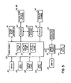
- the control 122 includes a user input/output (“I/O") interface 124 that provides various user operable input devices, for example, pushbuttons, switches, etc., as well as various sensory perceptible output devices, for example, lights, a visual display such as an LCD screen, etc.
- I/O user input/output
- the user I/O 124 permits the user to command the operation of individual servomotors and cylinders connected to outputs of the control 122.
- an operator can command the control 122 to provide an output signal to change a state of a solenoid 125.
- Changing the state of solenoid 125 changes the porting of pressurized air from the air source 126 to the tucking blade elevate cylinders 106, 108, thereby causing the cylinders 106, 108 to raise or lower the respective cylinder rods 102, 104 ( Fig. 4 ).
- an operator uses the user I/O 124 to command the control 122 to provide output signals to the solenoid 127 causing the tucking plate retract cylinder 120 to retract or advance the tucking blade 34.
- the user I/O permits an operator to enter tucking operation parameters, for example, the number of tucks to be placed around a corner, the length of each tuck and the number of stitches between the tucks.
- the tucking control 122 receives inputs from position feed and stop sensors 128, 129, respectively, and a foot switch 130 that is used by an operator to activate a tucking cycle.
- the tucking control 122 is connected to a sewing machine control 131 via digital I/O lines 132 that permit the tucking control 122 to provide operating commands to the sewing machine control 131.
- the sewing machine control receives operator commands via a user I/O 133 and a foot switch 134 and provides output signals to operate a sew head servomotor 135 and other devices on the sewing machine 22 in a known manner.
- the tucking control 122 has a ball nut position store 136 that is used to store the desired positions of the ball nut 36 that correspond to the tuck lengths input by the operator, thereby determining the length of each of the tucks.
- a a mattress 140 has a pillow top 141 sewn to one edge of a gusset 142 that, in turn, has another edge sewn to an upper decking panel 143 of a mattress body 147.
- the mattress body 147 is often of an innerspring construction.
- sewing the pillow top 141, gusset 142 and upper decking panel 143 together is relatively easy along the straight edges 144 of the mattress body 147.
- sewing the gusset 142 around a corner 145 of the mattress body 147 is more difficult, and various known techniques for sewing the gusset 142 around the corner have been previously discussed.
- tucks 146 are formed in the gusset material 142, so that as the upper decking material 143 and gusset material 142 are guided to sew a seam around the corner 145, the gusset appearance is predictable, pleasing and repeatable.
- a material folder 148 is mounted on an outer surface of the tucking arm 36.
- a strip of unfolded material strip 150 is manually fed into an inlet end 152, through the folder 148 and past an outlet end 154. As the material strip 150 passes trough the folder 148 it is folded over itself to form to opposed sides, and that folded configuration of the folded material 150 is referred to herein as the gusset 142.
- the tucking attachment 30 further includes an anvil 156 that is secured at an inner end 158 by a locking screw 160. Loosening the locking screw 160 permits the anvil 156 to be pivoted counterclockwise, away from the presser foot 26, about an axis of rotation 162 defined by the locking screw 160. When the anvil 156 is pivoted clockwise back to its illustrated position, it is located by a positive stop surface 164 on stop block 166. The locking screw 160 is then tightened to secure the anvil 156 in place.
- the anvil 156 has an inclined surface 167 that provides a subjacent support for the gusset material as the tucking blade 34 forms a tuck in the gusset.
- a decking guide 168 is mounted below the anvil 156 by means of a locking nut 170 and screw 172 slidably mounted in slot 174. By loosening the locking nut 170, the decking guide 168 can be slid to different positions in a direction parallel to the slot 174.
- the decking guide is positioned such that when an edge of the gusset material is aligned with an inner edge (not shown) of the decking guide, the two sides of the folded gusset will be of equal widths.
- an example of a first application is sewing a gusset 142 ( Fig. 6 ) to upper decking material 143.
- the operator uses the user I/O 124 to input parameters relating to the number of tucks to be used to form the corner, the length or size of each tuck and the number of stitches to be sewn between tucks.
- Those parameters are stored in a tuck number store 136, ball nut position store 137 and number of stitches store 138.
- the length of each tuck can be readily converted to a ball nut position.
- the operator raises the release pin 96 ( Fig. 2 ) so that the tucking attachment 30 can be pivoted away from the presser foot 26 ( Fig. 3 ), thereby giving the operator full access to the needle 28.
- the needle 28 is then threaded with the needle and bobbin threads in a known manner.
- the upper decking material 143 is fed over the base plate 24 and decking guide 168 and beneath the anvil 156.
- the decking material 143 is oriented such that one of the straight edges 144 is located beneath the presser foot at a point where the sewing operation is to begin.
- the tucking attachment 30 is then pivoted clockwise until the release pin 96 enters a detent 92b ( Fig. 3 ), thereby locating the tucking attachment 30 at its operating position.
- the operator utilizes the user I/O 124 ( Fig. 5 ) commanding the control 122 to provide an output signal to the solenoid 127 such that the tucking blade retract cylinder 120 is operated to retract the tucking blade 34.
- the material 150 is then manually fed through the folder 148 to form a gusset 142, and the gusset is placed beneath the presser foot 26.
- the operator again uses the user I/O 124 to command the control to advance the tucking blade 34 as shown in Fig. 8A .
- the tucking blade 34 is now located above the gusset 142 and on an upstream side of the presser foot 26, that is, to the right of the presser foot 26 as viewed in Fig. 6 .
- the operator commands the control 122 to turn on the sewing head motor 135 causing the upper decking panel material 143 and gusset 142 to be fed beneath the presser foot 26 from right to left, as viewed in Fig. 8A , while the needle 28 reciprocates to sew those material pieces together.
- the corner 145 of the upper decking material 143 is approached, an edge of the corner 145 moves past the position feed sensor 128 ( Fig. 1 ).
- the sensor 128 detects a reflection from reflector 178; and the output of the sensor 128 changes state.
- the tucking control 122 provides a slow feed signal via the digital I/O 132 to the sewing machine control 131.
- the sewing machine control 131 commands the sewing head motor 135 to decelerate to a slower feed.
- the edge of the corner 145 then passes below the stop sensor 129, and a reflected signal from its reflector 180 ( Fig. 7 ) causes its output to change state. Detecting that change of state, the tucking control 122 provides a stop command to the sewing machine control 122.
- the control 122 first determines, at 804, whether the ball nut 64 and hence, the tucking arm 36, is at its starting or home position. Normally, in executing a corner cycle, the ball nut starts from a common initial or home position, for example, referring to Fig. 2 , a position closer to the blocks 60, 62 than the illustrated position of the ball nut 64. In that position, the tucking blade 34 is at its furthest position away from the presser foot 26 as shown in Fig. 1 . If the control 122 determines that the ball nut 64 is not at its desired position, the control 122 provides, at 805, appropriate output signals to the tucking servomotor 46 to move the ball nut 64 to the home position.
- the control 122 reads a ball nut advance position from the ball nut position store 137.
- the control 122 provides output signals to the tucking blade servomotor 46 to rotate the ball screw 54 in a direction that moves the ball nut 64 outward away from the blocks 60, 62.
- the tucking blade 34 is pivoted or advanced toward the presser foot 26. In that process, the tucking blade 34 moves gusset material 142 over the inclined surface 167 of the anvil 156; and one portion of the gusset material is placed below another portion to form a tuck 146a ( Fig. 8B ).
- the control 122 determines, at 810, whether the ball nut has reached its desired position at which the tucking blade 34 is at its desired tuck length L. When that occurs, the control 122 then provides, at 812, a stop signal to the servomotor 46.
- the length L of the tuck 146a is variable and can be changed from one tuck to another by programming and storing different ball nut positions in the ball nut position store 137.
- the control 122 provides a start signal to the sewing head servomotor 135 that causes the needle 28 to reciprocate and the upper decking material 143 and gusset 142 are sewn together while being fed past the needle 28.
- the upper decking material 143 and the gusset 142 are manually guided by the operator, so that the tuck in the gusset 142 and the upper decking material 143 are being sewn together along a seam that lies on an arcuate path.
- the sewing machine control 131 receives feedback signals representing rotations of the sewing head servomotor 135, and those feedback signals are transferred to the tucking control 122 via the digital I/O 132.
- the tucking control reads the desired number of stitches to be sewn between the tucks from the number of stitches store 138.
- the control 122 detects, at 816, that the desired number of stitches have been sewn, the control 122 produces, at 818, a stop command to the sewing machine control 131 that then commands the sew head servomotor to stop.
- the tucking control 122 reads, at 819, a ball nut retract position from the ball nut position store and provides an output signal, at 820, commanding the tucking blade servomotor to reverse its operation and move the ball nut 64 toward its starting position.
- the control 122 When the commanded position of the ball nut is detected, at 822, the control 122 then provides a stop command, at 824, to the tucking blade servomotor 46. The tucking control 122 then reads from the tuck number store 136 the number of tucks that are to be formed around the corner 145 and determines, at 826, whether the last tuck has been formed. If not, the process returns to read, at 806, the next ball nut position that determines the length of the next tuck to be formed.
- the corner cycle then continues to automatically iterate the above-described process to successively form tucks of the same or different lengths, thereby allowing the operator to guide the gusset material 142 and sew a seam around a corner of the upper decking material 143.
- the tucking control 122 detects, at 826, the formation of the last tuck, the control 122 provides and end of corner signal via the digital I/O 132 to the sewing machine control 131, which allows the operator to sew along the next straight seam by operating the sewing machine in a normal manner independent of the tucking attachment 30.
- That ports pressurized fluid to the tucking blade elevate cylinders 106, 108 and causes the cylinders 106, 108 to elevate the tucking attachment 30, thereby providing additional clearance.
- a number of gussets 142 are sewn to a piece of upper decking material 143 using different values for the input parameters relating to the number of tucks, the same or different lengths of respective tucks and the number of stitches between tucks.
- the desired values for those parameters are determined, they are entered into the tucking control 122 by means of the user I/O 124.
- the tucking attachment 30 can be used to sew an upper decking material 186 to bedding foundation border material 188 that has been folded over onto the upper deck.
- the folder 148 can be removed from the tucking attachment 30.
- the upper decking material 186 is fed beneath the anvil 156 in place of the material 143.
- the bedding foundation border material 188 is placed over the anvil 156 and below tucking blade 34 in a manner similar to that previously described with respect to the gusset material 142.
- the sewing machine 22 is again operated in a known manner to sew a straight seam 190 ( Fig. 10 ).
- the operator activates the foot switch 130 to execute the corner cycle of Fig. 9 to sew tucks 192 in the bedding foundation border material 188 in a manner as previously described.
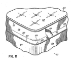
- a mattress 193 is constructed of a body or spring assembly 194 having a Euro-top 195 attached thereto.
- the Euro-top 195 is normally thicker than the pillow top 141 of Fig. 6 , and a Euro-top construction is often marketed with a higher premium.
- Various constructions of the Euro-top 195 may include a spring assembly, foam padding and/or other materials.
- a separate gusset type of material is sewn between a peripheral edge of the Euro-top 195 and a peripheral edge of the mattress body 194 in a manner similar to that described with respect to the use of a gusset 142 ( Fig. 6 ) to attach the pillow top 141 to the mattress body 147.
- the tucking attachment 30 of the sewing system 20 of Fig. 1 provides the capability of creating an alternative connective system.
- the Euro-top 195 is constructed of a border material 196 that is attached or sewn along its upper edge 197 to an outer peripheral edge of a generally planar top material 198.
- the lower portion of the border material 196 is formed into an integral material connector or offset 199, that in turn, is connected to the outer edge of the upper decking material 201.
- the border material 196 is connected to the upper decking material without requiring a separate connecting strip of material. This is achieved by first locating the upper decking material 201 over the base plate 24 ( Fig. 7 ) and then, locating the border material 196 over the anvil 156.
- a lower edge 204 of the border material 196 is generally aligned with an outer edge of the decking material 201; and the materials 196, 201 are located such that the needle 28 is positioned from the lower edge 204 a distance equal to a desired width of the offset 199.
- a seam 200 joining the border material 196 and upper decking material 201 is started parallel to a straight edge portion of the border lower edge 204.
- the tucking attachment 30 permits a bedding manufacturer to more easily, efficiently and economically create different appearances and styles in a Euro-top style mattress construction.
- the tucking attachment 30 provides a material tuck that is programmably variable in length, thereby providing great flexibility in controlling the fullness of material in sewing around a corner. Further, with the tucking attachment 30, the formation of each tuck is automatically precisely controlled, and therefore, the formation of tucks around a corner is repeatable from corner to corner.
- the tucking attachment 30 creates material tucks around corners with a minimum of operator intervention; and therefore, high quality material corners can be sewn without substantially increasing the manufacturing costs.
- the tucking attachment 30 is especially useful in joining components used to make a mattress or a bedding foundation.
- the tucking blade actuator is described as a DC servomotor; however, as will be appreciated, in alternative embodiments, the tucking blade actuator can be any programmable actuator, for example, a programmable cylinder that is pneumatic, hydraulic or electric. In addition, the tucking blade actuator can also be a stepping motor or a programmable AC motor. Similarly, in other alternative embodiments, the lever lift actuator can also be implemented using any of the above-mentioned actuators.
- the mechanical linkages of the tucking blade drive can be varied and different without adversely impacting the operation of the tucking blade.
- the tucking attachment is used to make right angle corners, as will be appreciated, the tucking attachment can be used to form tucks in any arcuate or curved seam.
- sensors 128, 129 are used to detect the presence of a corner; however, as will be appreciated, in alternative embodiments, the presence or start of a corner can be detected by the sewing machine operator with the sensors 128, 129.
- the tucking attachment 30 is shown mounted to the sewing machine 22: however, as will be appreciated, in other embodiments, the tucking attachment can be supported at its operating position by a support structure that is either suspended or free standing. Further, in its operation the tucking attachment 30 pivots the tucking blade 34 through a path that is substantially parallel to the linear direction that the sewing machine feeds the material past the needle. However, as will be appreciated, the tucking blade 34 can be operated and/or positioned such that the path of the tucking blade 34 is not substantially parallel to the linear direction that the sewing machine feeds the material past the needle. That may be desirable to form tucks having a different appearance or to provide the operator greater access to the presser foot and needle.
Landscapes
- Engineering & Computer Science (AREA)
- Textile Engineering (AREA)
- Sewing Machines And Sewing (AREA)
- Treatment Of Fiber Materials (AREA)
Claims (9)
- Procédé de couture d'un premier tissu (143, 186, 196) supporté sur une plaque de base (24) d'une machine à coudre (22) contre un deuxième tissu (142, 188, 201) au fur et à mesure que le deuxième tissu est plissé par un accessoire de plissage (30), la machine à coudre ayant un pied-de-biche (26) pour maintenir les premier et deuxième tissus (143, 142, 186, 188, 196, 201) et une aiguille alternative (28) pour coudre ensemble les premier et deuxième tissus, le procédé comprenant :le positionnement d'un premier tissu (143, 186, 196) au-dessus de la plaque de base (24) de la machine à coudre (22) en dessous du pied-de-biche (26) ;le positionnement d'une plaque d'enclume (156) au-dessus du premier tissu (143, 186, 196) et en dessous d'une lame de plissage (34) ;le positionnement d'un deuxième tissu (142, 188, 201) par-dessus la plaque d'enclume (156) et en dessous du pied-de-biche (26) à proximité du premier tissu (143, 186, 196) ;l'avancée de la lame de plissage (34) vers le pied-de-biche (26) pour engager le deuxième tissu (142, 188, 201) avec la lame de plissage (34) et former un pli d'une longueur programmable dans le deuxième tissu (142, 188, 201) par-dessus le premier tissu (143, 186, 196) ;l'actionnement de la machine à coudre (22) pour avancer le pli dans le deuxième tissu (142, 188, 201) et le premier tissu (143, 186, 196) devant l'aiguille alternative (28) et coudre un nombre souhaité de points à travers le pli dans le deuxième tissu (142, 188, 201) et le premier tissu (143, 186, 196) ;la rétraction de la lame de plissage (34) pour l'écarter du pied-de-biche (26) ; etl'itération des étapes ci-dessus d'avancée de la lame de plissage (34), d'actionnement de la machine à coudre (22) et de rétraction de la lame de plissage (34) afin de former et coudre un nombre souhaité de plis dans le deuxième tissu (142, 188, 201) contre le premier tissu (143, 186, 196).
- Procédé selon la revendication 1, comprenant en outre le guidage des premier et deuxième tissus (143, 142, 186, 188, 196, 201) durant le processus d'avancée de la lame de plissage (34), d'actionnement de la machine à coudre (22) et de rétraction de la lame de plissage (34) afin de former une couture joignant les plis dans le deuxième tissu (142, 188, 201) contre le premier tissu (143, 186, 196) le long d'une trajectoire précise.
- Procédé selon la revendication 2, comprenant en outre l'actionnement de la machine à coudre (22) pour avancer les premier et deuxième tissus (143, 142, 186, 188, 196, 201) devant l'aiguille alternative et coudre ensemble les premier et deuxième tissus (143, 142, 186, 188, 196, 201).
- Procédé selon la revendication 1, comprenant en outre :l'actionnement de la machine à coudre pour avancer les premier et deuxième tissus (143, 142, 186, 188, 196, 201) devant l'aiguille alternative (28) afin de former une couture essentiellement droite joignant ensemble les premier et deuxième tissus (143, 142, 186, 188, 196, 201);le guidage des premier et deuxième tissus (143, 142, 186, 188, 196, 201) durant le processus d'avancée de la lame de plissage (34), d'actionnement de la machine à coudre (22) et de rétraction de la lame de plissage (34) afin de former une couture courbe joignant les plis dans le deuxième tissu (142, 188, 201) contre le premier tissu (143, 186, 196) ; etl'itération des étapes ci-dessus d'actionnement de la machine à coudre (22) et de guidage des premier et deuxième tissus (143, 142, 186, 188, 196, 201) afin de former des coutures successives droites et courbes pour former une boucle essentiellement fermée.
- Procédé selon la revendication 4, dans lequel le premier tissu est un tissu de tablier supérieur (143) de matelas et le deuxième tissu est un tissu de gousset (142) servant à rattacher un surmatelas au matelas.
- Procédé selon la revendication 4, dans lequel le premier tissu est un tissu de tablir supérieur (186) pour une base de literie et le deuxième tissu est un tissu de bordure de base de literie (188).
- Procédé selon la revendication 4, dans lequel le premier tissu est un tissu de tablier supérieur (196) pour une base de literie et le deuxième tissu est un tissu de bordure Euro-top (201).
- Procédé d'utilisation d'une machine à coudre pour coudre un tissu de tablier supérieur (201) d'un corps de matelas à un tissu de bordure (196) d'un dessus de matelas, la machine à coudre (22) ayant une plaque de base (24), un pied-de-biche (26) et une aiguille alternative (28), le procédé comprenant :(a) le positionnement du tissu de tablier supérieur (201) sur la plaque de base (24) de la machine à coudre (22) en dessous du pied-de-biche (26) ;(b) le positionnement du tissu de bordure (196) au-dessus d'une plaque d'enclume (156) et en dessous du pied-de-biche (26) à proximité du tissu de tablier supérieur (201) de telle sorte que l'aiguille (28) se trouve à une distance souhaitée d'un bord du tissu de bordure (196) ;(c) la couture avec la machine à coudre (22) d'une couture essentiellement droite dans le tissu de bordure (196) et le tissu de tablier supérieur (201), la couture se trouvant à une distance souhaitée du bord du tissu de bordure (196) et essentiellement parallèle à celui-ci ;(d) la détermination que la couture se trouve au début d'un coin du tissu de tablier supérieur (196) ;(e) la formation d'un pli d'une longueur programmable dans le tissu de bordure (196) par-dessus le tissu de tablier supérieur (201) avec un accessoire de plissage (30) ;(f) la couture d'un nombre souhaité de points à travers le pli dans le tissu de bordure (196) et le tissu de tablier supérieur (201) avec la machine à coudre (22);(g) le guidage manuel du tissu de bordure (196) et du tissu de tablier supérieur (201) partiellement autour du coin durant les étapes ci-dessus de formation d'un pli et de couture d'un nombre souhaité de points ;(h) l'itération des étapes ci-dessus (e) à (g) afin de former un nombre souhaité de plis dans le tissu de bordure (196) et coudre une couture courbe dans le nombre souhaité de plis dans le tissu de bordure (196) et le tissu de tablier supérieur (201) tout en guidant le tissu de bordure (196) et le tissu de tablier supérieur (201) autour du coin, la couture étant placée essentiellement à la distance souhaitée du bord du tissu de bordure (196).
- Procédé selon la revendication 8, comprenant en outre l'itération des étapes (c) à (h) afin de coudre une couture essentiellement autour d'une périphérie du tissu de tablier supérieur (201) essentiellement à la distance souhaitée du bord du tissu de bordure (201).
Applications Claiming Priority (3)
| Application Number | Priority Date | Filing Date | Title |
|---|---|---|---|
| US277394 | 1999-03-26 | ||
| US10/277,394 US6889622B2 (en) | 2002-10-22 | 2002-10-22 | Programmable tucking attachment for a sewing machine and method |
| PCT/US2003/032210 WO2004038083A1 (fr) | 2002-10-22 | 2003-10-09 | Accessoire programmable de plissage pour machine a coudre et procede |
Publications (3)
| Publication Number | Publication Date |
|---|---|
| EP1560970A1 EP1560970A1 (fr) | 2005-08-10 |
| EP1560970A4 EP1560970A4 (fr) | 2005-12-28 |
| EP1560970B1 true EP1560970B1 (fr) | 2008-10-01 |
Family
ID=32093274
Family Applications (1)
| Application Number | Title | Priority Date | Filing Date |
|---|---|---|---|
| EP03776289A Expired - Lifetime EP1560970B1 (fr) | 2002-10-22 | 2003-10-09 | Accessoire programmable de plissage pour machine a coudre et procede |
Country Status (8)
| Country | Link |
|---|---|
| US (3) | US6889622B2 (fr) |
| EP (1) | EP1560970B1 (fr) |
| CN (1) | CN1774534B (fr) |
| AT (1) | ATE409771T1 (fr) |
| AU (1) | AU2003284059A1 (fr) |
| DE (1) | DE60323858D1 (fr) |
| ES (1) | ES2314260T3 (fr) |
| WO (1) | WO2004038083A1 (fr) |
Families Citing this family (33)
| Publication number | Priority date | Publication date | Assignee | Title |
|---|---|---|---|---|
| US6834603B1 (en) * | 2002-03-05 | 2004-12-28 | Atlanta Attachment Company | Attachment gusset with ruffled corners and system for automated manufacture of same |
| US7100525B1 (en) * | 2003-02-10 | 2006-09-05 | Atlanta Attachment Company, Inc. | System and method of finishing ruffled gussets/borders |
| US7383676B1 (en) | 2005-03-10 | 2008-06-10 | Atlanta Attachment Company | Packaging machine for bedding products |
| US7644671B2 (en) * | 2007-02-28 | 2010-01-12 | L&P Property Management Company | Method and system of manufacturing a mattress and components thereof |
| CN101315116B (zh) * | 2007-05-29 | 2011-07-20 | 高国兴 | 一种双轴变速箱 |
| CN101314895B (zh) * | 2007-05-29 | 2011-11-02 | 高国兴 | 新型打褶装置 |
| US7984681B1 (en) | 2007-11-20 | 2011-07-26 | Atlanta Attachment Company | Automatic panel sewing and flanging system |
| CN102021761A (zh) * | 2009-09-23 | 2011-04-20 | 吴江骏雅制衣有限公司 | 一种布料打折机 |
| CN102021763A (zh) * | 2009-09-23 | 2011-04-20 | 吴江骏雅制衣有限公司 | 缝纫打折机 |
| CN102021764A (zh) * | 2009-09-23 | 2011-04-20 | 吴江骏雅制衣有限公司 | 布料的打折机 |
| CN101748567B (zh) * | 2009-12-15 | 2012-09-05 | 安泰(德清)时装有限公司 | 一种缩皱缝纫结构及缩皱自导器 |
| US10792194B2 (en) | 2014-08-26 | 2020-10-06 | Curt G. Joa, Inc. | Apparatus and methods for securing elastic to a carrier web |
| CN104195754B (zh) * | 2014-09-26 | 2016-03-16 | 敬涛 | 一种工业缝纫机的高速自动打褶装置 |
| CN104389118B (zh) * | 2014-11-22 | 2015-12-16 | 宁波舒普机电股份有限公司 | 一种织带机的叠料装置 |
| CN104562453B (zh) * | 2015-01-26 | 2017-09-01 | 吴江市震宇缝制设备有限公司 | 一种缝制设备机头 |
| US11136154B2 (en) | 2017-09-22 | 2021-10-05 | Atlanta Attachment Company | Packaging machine for bedding products |
| CN107700086B (zh) * | 2017-11-22 | 2023-07-21 | 南通华勤纺织装饰有限公司 | 一种缝纫机自动打褶机构 |
| MX2020007614A (es) | 2018-01-29 | 2020-09-14 | Joa Curt G Inc | Aparato y metodo de fabricacion de una estructura compuesta elastica para un producto sanitario absorbente. |
| CN108754879A (zh) * | 2018-06-25 | 2018-11-06 | 池州市凯盛信息技术有限公司 | 一种服装加工用新型锁边机构 |
| CN108914410B (zh) * | 2018-10-18 | 2023-07-14 | 安徽即刻动身健身器械科技有限公司 | 一种布套连续缝制翻套的加工设备 |
| US11111615B2 (en) | 2018-11-30 | 2021-09-07 | L & P Property Management Company | Quilted panel |
| US11015275B2 (en) | 2018-11-30 | 2021-05-25 | L&P Property Management Company | Method of quilting layered input web |
| US11015274B2 (en) | 2018-11-30 | 2021-05-25 | L&P Property Management Company | Quilting machine |
| US11925538B2 (en) | 2019-01-07 | 2024-03-12 | Curt G. Joa, Inc. | Apparatus and method of manufacturing an elastic composite structure for an absorbent sanitary product |
| CN110409073B (zh) * | 2019-08-26 | 2025-01-03 | 郭长水 | 一种多功能气动打折机构及花边缝纫装置 |
| US12433797B2 (en) | 2019-09-04 | 2025-10-07 | Curt G. Joa, Inc. | Elastic entrapment with waist cap bonding |
| US11173072B2 (en) | 2019-09-05 | 2021-11-16 | Curt G. Joa, Inc. | Curved elastic with entrapment |
| EP4106699B1 (fr) | 2020-02-17 | 2025-10-15 | Curt G. Joa, Inc. | Structure composite élastique pour produit sanitaire absorbant et appareil et procédé de fabrication de ladite structure composite élastique |
| CN114232230A (zh) * | 2021-12-12 | 2022-03-25 | 广州喜登堡床垫机械有限公司 | 双层床垫围条自动打皱机 |
| US20230212802A1 (en) * | 2021-12-30 | 2023-07-06 | CreateMe Technologies LLC | Hem formation for automated garment manufacture |
| CN115338830B (zh) * | 2022-08-12 | 2026-03-17 | 广州市联柔机械设备有限公司 | 床网打边框设备及方法 |
| CN115449975B (zh) * | 2022-09-16 | 2023-09-29 | 安徽皓玥家纺有限公司 | 一种智能化羽绒被加工扭花工艺及其设备 |
| JP2024075207A (ja) * | 2022-11-22 | 2024-06-03 | Juki株式会社 | 折り目付け装置 |
Family Cites Families (37)
| Publication number | Priority date | Publication date | Assignee | Title |
|---|---|---|---|---|
| US1293725A (en) | 1917-07-16 | 1919-02-11 | Singer Mfg Co | Tucking attachment for sewing-machines. |
| US1911190A (en) | 1929-10-04 | 1933-05-30 | Harrison Charles | Tucking attachment for sewing machines |
| US2642828A (en) | 1950-06-14 | 1953-06-23 | Carroll Thomas Edward | Tuck-making guide |
| US2749858A (en) | 1953-06-23 | 1956-06-12 | Troy Textiles Inc | Bellows pleat folder attachment for sewing machine |
| US4012474A (en) * | 1963-07-17 | 1977-03-15 | General Atomic Company | Method for producing boron carbide spherules |
| JPS549110B2 (fr) | 1973-06-19 | 1979-04-21 | ||
| JPS5178470A (en) | 1974-12-27 | 1976-07-08 | France Bed Co | Matsutoresuno gaisojihoseisochi |
| JPS5178469A (fr) | 1974-12-27 | 1976-07-08 | France Bed Co | |
| US4073246A (en) | 1975-09-03 | 1978-02-14 | Burlington Industries, Inc. | Pleating machine |
| JPS52141753A (en) | 1976-05-21 | 1977-11-26 | Nippon Housei Gijiyutsu Kk | Device for forming three folds at curtain cloth or the like |
| US4157688A (en) * | 1978-01-03 | 1979-06-12 | Louisville Bedding Company | Ratio indicator for ruffling apparatus |
| FR2474833A1 (fr) * | 1980-02-06 | 1981-08-07 | Vestra Union Sa | Unite automatique par un rentrage programmable d'une partie d'un tissu, et le fixage automatique de ce rentrage au moyen d'un renfort thermocollant |
| DE3323541C2 (de) | 1983-06-30 | 1985-07-11 | MSI Mechanische Systeme Industrienähautomaten GmbH, 7500 Karlsruhe | Vorrichtung zum Einstülpen der Hosen- oder Rockbundenden |
| US4616584A (en) | 1985-02-19 | 1986-10-14 | The Singer Company | Method and apparatus for sewing mitered corners of box type articles |
| US5031554A (en) | 1989-04-26 | 1991-07-16 | Sewing Center Supply Co., Inc. | Method of forming a convoluted narrow fabric on a sewing machine |
| US5029542A (en) | 1989-07-19 | 1991-07-09 | Automated Machinery Systems, Inc. | Automatic tuck forming apparatus having improved clamp means |
| US5114056A (en) * | 1990-09-07 | 1992-05-19 | Mim Industries, Inc. | Pleating method and apparatus |
| US5315942A (en) | 1992-09-29 | 1994-05-31 | Pantusco Frank S | High speed sewing machine ruffler |
| US5285542A (en) | 1993-03-10 | 1994-02-15 | West Gordon W | Mattress cover |
| WO1995004852A1 (fr) | 1993-08-04 | 1995-02-16 | Porter Sewing Machines, Inc. | Procede et machine d'assemblage sur matelas d'une doublure a bourrelets |
| CN2169638Y (zh) * | 1993-10-14 | 1994-06-22 | 高鸣 | 缝纫机打褶装置 |
| JP2587402Y2 (ja) | 1993-12-28 | 1998-12-16 | 有限会社新研工業所 | 着脱式ひだ取り機 |
| US5771829A (en) | 1994-12-30 | 1998-06-30 | Batesville Casket Company, Inc. | Method and apparatus for shirring a fabric |
| DE29614273U1 (de) | 1995-05-24 | 1996-10-17 | Dürkopp Adler AG, 33719 Bielefeld | Faltvorrichtung für einen Nähautomaten |
| FR2745987B1 (fr) | 1996-03-15 | 1998-06-12 | Coulisse de froncage et son procede de fabrication | |
| JPH09266995A (ja) | 1996-04-03 | 1997-10-14 | Mori Katsuji | ミシンに取り付けて利用されるひだ取り器 |
| JP2914620B2 (ja) | 1996-08-01 | 1999-07-05 | 中日本ジューキ株式会社 | カーテンヒダ縫い自動機 |
| US5915319A (en) * | 1997-08-15 | 1999-06-29 | Atlanta Attachment Company | Method and apparatus for producing a hemmed, folded, and seamed finished workpiece |
| US5966758A (en) | 1997-10-10 | 1999-10-19 | Karam; Linda Hilborn | Adjustable dust ruffle device |
| US5983814A (en) * | 1998-03-10 | 1999-11-16 | Galkin Automated Products | Automatic mattress handle sewing work station |
| US6012403A (en) * | 1998-05-01 | 2000-01-11 | L&P Property Management Company | Combination printing and quilting method and apparatus |
| US6202579B1 (en) * | 2000-01-11 | 2001-03-20 | Sealy Technology Llc | Automated apparatus for manufacture of mattress borders with sewn handles |
| WO2001090467A2 (fr) | 2000-05-24 | 2001-11-29 | G.M. Pfaff Aktiengesellschaft In Insolvenz | Dispositif de couture |
| US6574815B2 (en) | 2001-04-10 | 2003-06-10 | Sealy Technology Llc | Pillowtop/panel attachment gusset with ruffled corners |
| US6834603B1 (en) | 2002-03-05 | 2004-12-28 | Atlanta Attachment Company | Attachment gusset with ruffled corners and system for automated manufacture of same |
| CN2576751Y (zh) * | 2002-10-10 | 2003-10-01 | 上海锦鸡机械制造有限公司 | 缝纫机的打褶装置 |
| US6802271B2 (en) | 2003-01-08 | 2004-10-12 | Atlanta Attachment Company | Automatic border sewing system |
-
2002
- 2002-10-22 US US10/277,394 patent/US6889622B2/en not_active Expired - Lifetime
-
2003
- 2003-10-09 AU AU2003284059A patent/AU2003284059A1/en not_active Abandoned
- 2003-10-09 DE DE60323858T patent/DE60323858D1/de not_active Expired - Lifetime
- 2003-10-09 ES ES03776289T patent/ES2314260T3/es not_active Expired - Lifetime
- 2003-10-09 AT AT03776289T patent/ATE409771T1/de not_active IP Right Cessation
- 2003-10-09 WO PCT/US2003/032210 patent/WO2004038083A1/fr not_active Ceased
- 2003-10-09 EP EP03776289A patent/EP1560970B1/fr not_active Expired - Lifetime
- 2003-10-09 CN CN2003801072806A patent/CN1774534B/zh not_active Expired - Fee Related
-
2005
- 2005-01-31 US US11/047,103 patent/US7021227B2/en not_active Expired - Lifetime
-
2006
- 2006-04-03 US US11/278,491 patent/US7617787B2/en not_active Expired - Lifetime
Also Published As
| Publication number | Publication date |
|---|---|
| ES2314260T3 (es) | 2009-03-16 |
| US7617787B2 (en) | 2009-11-17 |
| AU2003284059A1 (en) | 2004-05-13 |
| CN1774534B (zh) | 2011-04-13 |
| EP1560970A4 (fr) | 2005-12-28 |
| ATE409771T1 (de) | 2008-10-15 |
| DE60323858D1 (de) | 2008-11-13 |
| CN1774534A (zh) | 2006-05-17 |
| US20050183646A1 (en) | 2005-08-25 |
| US20040074428A1 (en) | 2004-04-22 |
| US6889622B2 (en) | 2005-05-10 |
| US7021227B2 (en) | 2006-04-04 |
| WO2004038083A1 (fr) | 2004-05-06 |
| EP1560970A1 (fr) | 2005-08-10 |
| US20060180068A1 (en) | 2006-08-17 |
Similar Documents
| Publication | Publication Date | Title |
|---|---|---|
| EP1560970B1 (fr) | Accessoire programmable de plissage pour machine a coudre et procede | |
| US5586511A (en) | Method and apparatus for assembly of pillow-top mattress covers | |
| US8042478B2 (en) | Automatic panel cutting and seaming system | |
| US7412936B2 (en) | Attachment gusset with ruffled corners and system for automated manufacture of same | |
| JP5616587B2 (ja) | ベルトループ付けミシン | |
| CA2459573C (fr) | Soufflet de fixation de coussin/panneau a coins a volant | |
| CN107304496A (zh) | 缝纫机 | |
| CA2448868A1 (fr) | Systeme de production de bordures de matelas | |
| JPS6045381A (ja) | キルテイング模様自動縫い方法及び装置 | |
| JP2000300874A (ja) | ボタン孔ミシン | |
| US7100525B1 (en) | System and method of finishing ruffled gussets/borders | |
| EP3068937B1 (fr) | Machine à piquer à aiguilles multiples et procédé de piquage correspondant | |
| EP0888473B1 (fr) | Appareil a pied presseur reglable pour machines a coudre destinees a la fabrication de matelas | |
| JP2002126383A (ja) | 畳縫着装置および縫着方法 | |
| US20030213418A1 (en) | Mattress label sewing clamp | |
| JP2734772B2 (ja) | 加工布折曲げ装置 | |
| JP5037109B2 (ja) | ミシン | |
| JPH10118363A (ja) | ジグザグミシンの縫い模様及びジグザグミシンの縫い模様の形成方法 | |
| JP3503132B2 (ja) | 穴かがりミシン及び穴かがり形成方法 | |
| JP4681765B2 (ja) | ミシンの布ガイド装置及びミシン | |
| JPS636235B2 (fr) | ||
| JPH0424044A (ja) | 根巻きボタン付けミシン | |
| JPH06142368A (ja) | テープ片縫着用ミシン | |
| JPH0141400Y2 (fr) | ||
| JP2002085872A (ja) | 玉縁ミシンの布押え装置 |
Legal Events
| Date | Code | Title | Description |
|---|---|---|---|
| PUAI | Public reference made under article 153(3) epc to a published international application that has entered the european phase |
Free format text: ORIGINAL CODE: 0009012 |
|
| 17P | Request for examination filed |
Effective date: 20050420 |
|
| AK | Designated contracting states |
Kind code of ref document: A1 Designated state(s): AT BE BG CH CY CZ DE DK EE ES FI FR GB GR HU IE IT LI LU MC NL PT RO SE SI SK TR |
|
| AX | Request for extension of the european patent |
Extension state: AL LT LV MK |
|
| A4 | Supplementary search report drawn up and despatched |
Effective date: 20051111 |
|
| DAX | Request for extension of the european patent (deleted) | ||
| 17Q | First examination report despatched |
Effective date: 20061219 |
|
| GRAP | Despatch of communication of intention to grant a patent |
Free format text: ORIGINAL CODE: EPIDOSNIGR1 |
|
| GRAS | Grant fee paid |
Free format text: ORIGINAL CODE: EPIDOSNIGR3 |
|
| GRAA | (expected) grant |
Free format text: ORIGINAL CODE: 0009210 |
|
| AK | Designated contracting states |
Kind code of ref document: B1 Designated state(s): AT BE BG CH CY CZ DE DK EE ES FI FR GB GR HU IE IT LI LU MC NL PT RO SE SI SK TR |
|
| REG | Reference to a national code |
Ref country code: GB Ref legal event code: FG4D |
|
| REG | Reference to a national code |
Ref country code: CH Ref legal event code: EP |
|
| REG | Reference to a national code |
Ref country code: IE Ref legal event code: FG4D |
|
| REF | Corresponds to: |
Ref document number: 60323858 Country of ref document: DE Date of ref document: 20081113 Kind code of ref document: P |
|
| PG25 | Lapsed in a contracting state [announced via postgrant information from national office to epo] |
Ref country code: SI Free format text: LAPSE BECAUSE OF FAILURE TO SUBMIT A TRANSLATION OF THE DESCRIPTION OR TO PAY THE FEE WITHIN THE PRESCRIBED TIME-LIMIT Effective date: 20081001 |
|
| REG | Reference to a national code |
Ref country code: ES Ref legal event code: FG2A Ref document number: 2314260 Country of ref document: ES Kind code of ref document: T3 |
|
| NLV1 | Nl: lapsed or annulled due to failure to fulfill the requirements of art. 29p and 29m of the patents act | ||
| PG25 | Lapsed in a contracting state [announced via postgrant information from national office to epo] |
Ref country code: AT Free format text: LAPSE BECAUSE OF FAILURE TO SUBMIT A TRANSLATION OF THE DESCRIPTION OR TO PAY THE FEE WITHIN THE PRESCRIBED TIME-LIMIT Effective date: 20081001 Ref country code: BG Free format text: LAPSE BECAUSE OF FAILURE TO SUBMIT A TRANSLATION OF THE DESCRIPTION OR TO PAY THE FEE WITHIN THE PRESCRIBED TIME-LIMIT Effective date: 20090101 |
|
| PG25 | Lapsed in a contracting state [announced via postgrant information from national office to epo] |
Ref country code: MC Free format text: LAPSE BECAUSE OF NON-PAYMENT OF DUE FEES Effective date: 20081031 Ref country code: FI Free format text: LAPSE BECAUSE OF FAILURE TO SUBMIT A TRANSLATION OF THE DESCRIPTION OR TO PAY THE FEE WITHIN THE PRESCRIBED TIME-LIMIT Effective date: 20081001 Ref country code: PT Free format text: LAPSE BECAUSE OF FAILURE TO SUBMIT A TRANSLATION OF THE DESCRIPTION OR TO PAY THE FEE WITHIN THE PRESCRIBED TIME-LIMIT Effective date: 20090302 Ref country code: NL Free format text: LAPSE BECAUSE OF FAILURE TO SUBMIT A TRANSLATION OF THE DESCRIPTION OR TO PAY THE FEE WITHIN THE PRESCRIBED TIME-LIMIT Effective date: 20081001 |
|
| REG | Reference to a national code |
Ref country code: CH Ref legal event code: PL |
|
| REG | Reference to a national code |
Ref country code: IE Ref legal event code: MM4A |
|
| PG25 | Lapsed in a contracting state [announced via postgrant information from national office to epo] |
Ref country code: EE Free format text: LAPSE BECAUSE OF FAILURE TO SUBMIT A TRANSLATION OF THE DESCRIPTION OR TO PAY THE FEE WITHIN THE PRESCRIBED TIME-LIMIT Effective date: 20081001 Ref country code: BE Free format text: LAPSE BECAUSE OF FAILURE TO SUBMIT A TRANSLATION OF THE DESCRIPTION OR TO PAY THE FEE WITHIN THE PRESCRIBED TIME-LIMIT Effective date: 20081001 Ref country code: DK Free format text: LAPSE BECAUSE OF FAILURE TO SUBMIT A TRANSLATION OF THE DESCRIPTION OR TO PAY THE FEE WITHIN THE PRESCRIBED TIME-LIMIT Effective date: 20081001 Ref country code: RO Free format text: LAPSE BECAUSE OF FAILURE TO SUBMIT A TRANSLATION OF THE DESCRIPTION OR TO PAY THE FEE WITHIN THE PRESCRIBED TIME-LIMIT Effective date: 20081001 |
|
| PLBE | No opposition filed within time limit |
Free format text: ORIGINAL CODE: 0009261 |
|
| STAA | Information on the status of an ep patent application or granted ep patent |
Free format text: STATUS: NO OPPOSITION FILED WITHIN TIME LIMIT |
|
| PG25 | Lapsed in a contracting state [announced via postgrant information from national office to epo] |
Ref country code: SE Free format text: LAPSE BECAUSE OF FAILURE TO SUBMIT A TRANSLATION OF THE DESCRIPTION OR TO PAY THE FEE WITHIN THE PRESCRIBED TIME-LIMIT Effective date: 20090101 Ref country code: CZ Free format text: LAPSE BECAUSE OF FAILURE TO SUBMIT A TRANSLATION OF THE DESCRIPTION OR TO PAY THE FEE WITHIN THE PRESCRIBED TIME-LIMIT Effective date: 20081001 |
|
| 26N | No opposition filed |
Effective date: 20090702 |
|
| PG25 | Lapsed in a contracting state [announced via postgrant information from national office to epo] |
Ref country code: SK Free format text: LAPSE BECAUSE OF FAILURE TO SUBMIT A TRANSLATION OF THE DESCRIPTION OR TO PAY THE FEE WITHIN THE PRESCRIBED TIME-LIMIT Effective date: 20081001 |
|
| PG25 | Lapsed in a contracting state [announced via postgrant information from national office to epo] |
Ref country code: CH Free format text: LAPSE BECAUSE OF NON-PAYMENT OF DUE FEES Effective date: 20081031 Ref country code: LI Free format text: LAPSE BECAUSE OF NON-PAYMENT OF DUE FEES Effective date: 20081031 Ref country code: IE Free format text: LAPSE BECAUSE OF NON-PAYMENT OF DUE FEES Effective date: 20081009 |
|
| PG25 | Lapsed in a contracting state [announced via postgrant information from national office to epo] |
Ref country code: CY Free format text: LAPSE BECAUSE OF FAILURE TO SUBMIT A TRANSLATION OF THE DESCRIPTION OR TO PAY THE FEE WITHIN THE PRESCRIBED TIME-LIMIT Effective date: 20081001 Ref country code: HU Free format text: LAPSE BECAUSE OF FAILURE TO SUBMIT A TRANSLATION OF THE DESCRIPTION OR TO PAY THE FEE WITHIN THE PRESCRIBED TIME-LIMIT Effective date: 20090402 Ref country code: LU Free format text: LAPSE BECAUSE OF NON-PAYMENT OF DUE FEES Effective date: 20081009 |
|
| PG25 | Lapsed in a contracting state [announced via postgrant information from national office to epo] |
Ref country code: TR Free format text: LAPSE BECAUSE OF FAILURE TO SUBMIT A TRANSLATION OF THE DESCRIPTION OR TO PAY THE FEE WITHIN THE PRESCRIBED TIME-LIMIT Effective date: 20081001 |
|
| PG25 | Lapsed in a contracting state [announced via postgrant information from national office to epo] |
Ref country code: GR Free format text: LAPSE BECAUSE OF FAILURE TO SUBMIT A TRANSLATION OF THE DESCRIPTION OR TO PAY THE FEE WITHIN THE PRESCRIBED TIME-LIMIT Effective date: 20090102 |
|
| REG | Reference to a national code |
Ref country code: FR Ref legal event code: PLFP Year of fee payment: 13 |
|
| PGFP | Annual fee paid to national office [announced via postgrant information from national office to epo] |
Ref country code: FR Payment date: 20150908 Year of fee payment: 13 |
|
| REG | Reference to a national code |
Ref country code: FR Ref legal event code: ST Effective date: 20170630 |
|
| PG25 | Lapsed in a contracting state [announced via postgrant information from national office to epo] |
Ref country code: FR Free format text: LAPSE BECAUSE OF NON-PAYMENT OF DUE FEES Effective date: 20161102 |
|
| PGFP | Annual fee paid to national office [announced via postgrant information from national office to epo] |
Ref country code: DE Payment date: 20190924 Year of fee payment: 17 |
|
| PGFP | Annual fee paid to national office [announced via postgrant information from national office to epo] |
Ref country code: IT Payment date: 20191009 Year of fee payment: 17 Ref country code: ES Payment date: 20191104 Year of fee payment: 17 |
|
| PGFP | Annual fee paid to national office [announced via postgrant information from national office to epo] |
Ref country code: GB Payment date: 20191010 Year of fee payment: 17 |
|
| REG | Reference to a national code |
Ref country code: DE Ref legal event code: R119 Ref document number: 60323858 Country of ref document: DE |
|
| GBPC | Gb: european patent ceased through non-payment of renewal fee |
Effective date: 20201009 |
|
| PG25 | Lapsed in a contracting state [announced via postgrant information from national office to epo] |
Ref country code: DE Free format text: LAPSE BECAUSE OF NON-PAYMENT OF DUE FEES Effective date: 20210501 |
|
| PG25 | Lapsed in a contracting state [announced via postgrant information from national office to epo] |
Ref country code: GB Free format text: LAPSE BECAUSE OF NON-PAYMENT OF DUE FEES Effective date: 20201009 |
|
| PG25 | Lapsed in a contracting state [announced via postgrant information from national office to epo] |
Ref country code: IT Free format text: LAPSE BECAUSE OF NON-PAYMENT OF DUE FEES Effective date: 20201009 |
|
| REG | Reference to a national code |
Ref country code: ES Ref legal event code: FD2A Effective date: 20220127 |
|
| PG25 | Lapsed in a contracting state [announced via postgrant information from national office to epo] |
Ref country code: ES Free format text: LAPSE BECAUSE OF NON-PAYMENT OF DUE FEES Effective date: 20201010 |