EP1560694B1 - Verfahren zur herstellung von produkten aus einer thermoplastischen masse - Google Patents
Verfahren zur herstellung von produkten aus einer thermoplastischen masse Download PDFInfo
- Publication number
- EP1560694B1 EP1560694B1 EP03795499A EP03795499A EP1560694B1 EP 1560694 B1 EP1560694 B1 EP 1560694B1 EP 03795499 A EP03795499 A EP 03795499A EP 03795499 A EP03795499 A EP 03795499A EP 1560694 B1 EP1560694 B1 EP 1560694B1
- Authority
- EP
- European Patent Office
- Prior art keywords
- plastic
- slide
- mold cavity
- mold
- movement
- Prior art date
- Legal status (The legal status is an assumption and is not a legal conclusion. Google has not performed a legal analysis and makes no representation as to the accuracy of the status listed.)
- Expired - Lifetime
Links
Images
Classifications
-
- B—PERFORMING OPERATIONS; TRANSPORTING
- B29—WORKING OF PLASTICS; WORKING OF SUBSTANCES IN A PLASTIC STATE IN GENERAL
- B29C—SHAPING OR JOINING OF PLASTICS; SHAPING OF MATERIAL IN A PLASTIC STATE, NOT OTHERWISE PROVIDED FOR; AFTER-TREATMENT OF THE SHAPED PRODUCTS, e.g. REPAIRING
- B29C43/00—Compression moulding, i.e. applying external pressure to flow the moulding material; Apparatus therefor
- B29C43/32—Component parts, details or accessories; Auxiliary operations
- B29C43/36—Moulds for making articles of definite length, i.e. discrete articles
- B29C43/361—Moulds for making articles of definite length, i.e. discrete articles with pressing members independently movable of the parts for opening or closing the mould, e.g. movable pistons
-
- B—PERFORMING OPERATIONS; TRANSPORTING
- B29—WORKING OF PLASTICS; WORKING OF SUBSTANCES IN A PLASTIC STATE IN GENERAL
- B29C—SHAPING OR JOINING OF PLASTICS; SHAPING OF MATERIAL IN A PLASTIC STATE, NOT OTHERWISE PROVIDED FOR; AFTER-TREATMENT OF THE SHAPED PRODUCTS, e.g. REPAIRING
- B29C43/00—Compression moulding, i.e. applying external pressure to flow the moulding material; Apparatus therefor
- B29C43/32—Component parts, details or accessories; Auxiliary operations
- B29C43/52—Heating or cooling
-
- B—PERFORMING OPERATIONS; TRANSPORTING
- B29—WORKING OF PLASTICS; WORKING OF SUBSTANCES IN A PLASTIC STATE IN GENERAL
- B29C—SHAPING OR JOINING OF PLASTICS; SHAPING OF MATERIAL IN A PLASTIC STATE, NOT OTHERWISE PROVIDED FOR; AFTER-TREATMENT OF THE SHAPED PRODUCTS, e.g. REPAIRING
- B29C45/00—Injection moulding, i.e. forcing the required volume of moulding material through a nozzle into a closed mould; Apparatus therefor
- B29C45/17—Component parts, details or accessories; Auxiliary operations
- B29C45/46—Means for plasticising or homogenising the moulding material or forcing it into the mould
- B29C45/56—Means for plasticising or homogenising the moulding material or forcing it into the mould using mould parts movable during or after injection, e.g. injection-compression moulding
- B29C45/561—Injection-compression moulding
-
- B—PERFORMING OPERATIONS; TRANSPORTING
- B29—WORKING OF PLASTICS; WORKING OF SUBSTANCES IN A PLASTIC STATE IN GENERAL
- B29C—SHAPING OR JOINING OF PLASTICS; SHAPING OF MATERIAL IN A PLASTIC STATE, NOT OTHERWISE PROVIDED FOR; AFTER-TREATMENT OF THE SHAPED PRODUCTS, e.g. REPAIRING
- B29C43/00—Compression moulding, i.e. applying external pressure to flow the moulding material; Apparatus therefor
- B29C43/32—Component parts, details or accessories; Auxiliary operations
- B29C43/58—Measuring, controlling or regulating
- B29C2043/5808—Measuring, controlling or regulating pressure or compressing force
-
- B—PERFORMING OPERATIONS; TRANSPORTING
- B29—WORKING OF PLASTICS; WORKING OF SUBSTANCES IN A PLASTIC STATE IN GENERAL
- B29C—SHAPING OR JOINING OF PLASTICS; SHAPING OF MATERIAL IN A PLASTIC STATE, NOT OTHERWISE PROVIDED FOR; AFTER-TREATMENT OF THE SHAPED PRODUCTS, e.g. REPAIRING
- B29C45/00—Injection moulding, i.e. forcing the required volume of moulding material through a nozzle into a closed mould; Apparatus therefor
- B29C2045/0094—Injection moulding, i.e. forcing the required volume of moulding material through a nozzle into a closed mould; Apparatus therefor injection moulding of small-sized articles, e.g. microarticles, ultra thin articles
-
- B—PERFORMING OPERATIONS; TRANSPORTING
- B29—WORKING OF PLASTICS; WORKING OF SUBSTANCES IN A PLASTIC STATE IN GENERAL
- B29C—SHAPING OR JOINING OF PLASTICS; SHAPING OF MATERIAL IN A PLASTIC STATE, NOT OTHERWISE PROVIDED FOR; AFTER-TREATMENT OF THE SHAPED PRODUCTS, e.g. REPAIRING
- B29C45/00—Injection moulding, i.e. forcing the required volume of moulding material through a nozzle into a closed mould; Apparatus therefor
- B29C2045/0098—Injection moulding, i.e. forcing the required volume of moulding material through a nozzle into a closed mould; Apparatus therefor shearing of the moulding material, e.g. for obtaining molecular orientation or reducing the viscosity
-
- B—PERFORMING OPERATIONS; TRANSPORTING
- B29—WORKING OF PLASTICS; WORKING OF SUBSTANCES IN A PLASTIC STATE IN GENERAL
- B29C—SHAPING OR JOINING OF PLASTICS; SHAPING OF MATERIAL IN A PLASTIC STATE, NOT OTHERWISE PROVIDED FOR; AFTER-TREATMENT OF THE SHAPED PRODUCTS, e.g. REPAIRING
- B29C45/00—Injection moulding, i.e. forcing the required volume of moulding material through a nozzle into a closed mould; Apparatus therefor
- B29C45/17—Component parts, details or accessories; Auxiliary operations
- B29C45/46—Means for plasticising or homogenising the moulding material or forcing it into the mould
- B29C45/56—Means for plasticising or homogenising the moulding material or forcing it into the mould using mould parts movable during or after injection, e.g. injection-compression moulding
- B29C45/561—Injection-compression moulding
- B29C2045/5635—Mould integrated compression drive means
-
- B—PERFORMING OPERATIONS; TRANSPORTING
- B29—WORKING OF PLASTICS; WORKING OF SUBSTANCES IN A PLASTIC STATE IN GENERAL
- B29C—SHAPING OR JOINING OF PLASTICS; SHAPING OF MATERIAL IN A PLASTIC STATE, NOT OTHERWISE PROVIDED FOR; AFTER-TREATMENT OF THE SHAPED PRODUCTS, e.g. REPAIRING
- B29C33/00—Moulds or cores; Details thereof or accessories therefor
- B29C33/20—Opening, closing or clamping
-
- B—PERFORMING OPERATIONS; TRANSPORTING
- B29—WORKING OF PLASTICS; WORKING OF SUBSTANCES IN A PLASTIC STATE IN GENERAL
- B29L—INDEXING SCHEME ASSOCIATED WITH SUBCLASS B29C, RELATING TO PARTICULAR ARTICLES
- B29L2031/00—Other particular articles
- B29L2031/756—Microarticles, nanoarticles
Definitions
- the invention relates to a method for manufacturing products from an at least thermoplastically deformable material. Such a method is known, for instance, as injection molding.
- the material to be formed such as plastic is heated in a plasticizing device to a temperature such that the material becomes virtually liquid, at least plastic and low-viscous, whereupon the material is introduced under high pressure into a mold cavity of an injection molding mold.
- the material is distributed such that the mold cavity is completely filled, whereupon the material is allowed to cure by cooling down.
- the product is taken out by opening the mold and ejecting the product.
- a further disadvantage of this apparatus is that when materials are used with a low viscosity and/or with shallow mold halves, the material flows from the mold cavity before the mold halves are moved together, so that the earlier mentioned problems occur to an even larger extent.
- US 4522778 discloses a method and apparatus for the production of parts made from plastic material using an injection press in which the mold cavity is defined by a mold surface and the surface of a moveable piston. Firstly, the material is introduced into the mold cavity and during injection the piston is kept stationary for a time to form a rough mold and then retracted to form a parison. Secondly, after injection has been completed the piston is advanced again, and maintained in position while cooling takes place. Thirdly, the mold is opened and the part rejected.
- EP 0999029 discloses a molding machine for molding microparts, which includes a plasticizing portion operatively connected to an injection portion and a mold portion.
- a linear member is associated with the injection portion to permit molding times of 0. 01 seconds at pressures up to about 690 MPa during injection of the molten plastics material into the mold portion.
- the shape of the mold cavity complies with the micro part to be manufactured.
- plastics in particular also plastics with a high melt, i.e. plastics with a low viscosity in plastic state.
- An object of the invention is to provide a method with which, in a relatively rapid and simple manner, products can be manufactured, with relatively simple means, which products, moreover, can have relatively large, thin-walled surfaces, in particular products with wall thicknesses which are relatively small and flow path which are relatively long, smaller or longer, respectively, than matching the melt flow index associated with the material from which the product is manufactured.
- the disclosure further contemplates providing an improved use of an injection mold with a slide.
- the invention relates to a method for forming products, characterized by the features of claim 1.
- plastic is introduced into the mold cavity while the or each slide is retracted therefrom at least partly or is pushed back upon injection, so that additional flow space is obtained.
- the resistance the plastic experiences is reduced, so that the injection pressure can be kept low, for instance largely below the standard injection pressure for conventional injection molding of a similar type of product from the same plastic.
- standard pressures can be read from standard tables and, as a rule, are dependent on the plastic and the manner of injection, the projected surface of the products to be formed jointly and the wall thicknesses.
- the closing pressure can also be kept low in relation to conventional injection molding, readable from the same or comparable tables on the basis of substantially the same quantities. This is directly clear to the skilled person.
- the or each slide is moved rapidly into the mold cavity, such that the eventual product shape is obtained.
- the speed of the or each slide is then set such that adiabatic heat development occurs in the plastic, so that the temperature is increased again to approximately the melting temperature of the plastic.
- partially solidified material will become liquid again and be pushed further into the mold cavity, while, furthermore, the remaining flow paths are relatively short so that relatively thin product parts can be formed.
- the rate of movement of the or each slide is preferably high, such that the complete movement of the slides is carried out in a fraction of the cycle time of a product cycle, for instance in less than 10%, more in particular in less than 3% of the cycle time, preferably less than some tenths or hundredths of seconds, more in particular microseconds.
- this rate is set such that the desired temperature increase occurs, while the plastic properties are prevented from being adversely thermally influenced.
- the distance between the end of the or each slide, leading in the direction of movement and facing the mold cavity in the retracted position, at least partly moved from the mold cavity, and an oppositely located wall part of the mold cavity or slide is set depending on at least the melt of the plastic, i.e. the viscosity of the plastic upon injection.
- the distance is to be slightly greater than with a lower melt.
- a thermoplastic material such as a plastic, in particular a thermoplastic plastic
- a thermoplastic material can be introduced into a mold cavity while the mold as such is closed and the or each slide is in, or is being brought into, a retracted position at introduction of the material, so that the volume of the mold cavity is relatively large with respect to the volume of the product to be eventually formed.
- the or each slide can be moved forcefully and, in particular, with speed into the mold cavity, at least into the material introduced therein, so that this is pushed away. With it, a speed is developed such that, as a result of the movement of the or each slide, heat development occurs in the material.
- the movement means are designed such that the slide can move at the desired high speed and with the desired accuracy.
- the movement means and the slide are designed such that adiabatic heat development occurs, so that the temperature in the material rises preferably above the melting temperature of the respective material.
- the closing means are included at least partly in or on the mold, preferably such that no press is required or that a press without guide rod can suffice.
- blocking means can be provided on the mold for holding the mold in closed condition during introduction of the material and displacement of the or each slide.
- the mold With the apparatus, the mold can be held closed with relatively little closing pressure and the plastic can be introduced, in comparison with a conventional injection molding apparatus.
- feed pressures of between, for instance, 350 bars and 1000 bars or more are used, with closing pressures of, for instance, 0.25 to 1.25 ton/cm 2 , depending on, in particular, the material used, the wall thickness and the maximum flow path.
- closing pressures of, for instance, 0.25 to 1.25 ton/cm 2 , depending on, in particular, the material used, the wall thickness and the maximum flow path.
- a feed pressure of, for instance, between 0 and 200 bars excess pressure can suffice, while relatively low pressures are preferred, for instance of some tens of bars or less.
- an operating pressure of approximately 300 bar (operating pressure of the cylinders of the slides) is given, while the closing pressure can be, for instance, less than 0.2 ton/cm 2 .
- a closing pressure of 0.025 to 0.1 ton/cm 2 instead of between 0.25 to 1.25 ton/cm 2 can suffice.
- the advantage appears to be achieved that due to the high speed of the or each slide, as a result of friction, so much heat is introduced into the material that solidification of the material, in particular against the mold parts and in the flow front thereof, is undone so that the viscosity of the material is reduced again, while the remaining length of the flow paths for this flow front at the start of the movement of the or each slide has been considerably reduced relative to the original length thereof.
- the material can be distributed in the entire mold cavity with less pressure. As the mold is then closed, in a simple manner, the material is prevented from flowing away prematurely.
- a feed rate can be used of between 100 and 2000 mm/s, more in particular of between 500 and 1000 mm/s. This rate is selected depending on the solidification rate of the plastic used, while it holds that the more quickly the plastic solidifies, the higher the feed rate is chosen to be. Moreover, the rate is selected depending on the mold geometry and, in particular, the de-aeration, such that undesired pressure increase in the mold cavity by compression of air is prevented.
- wedge-shaped elements are used which, viewed from the mold cavity, are moved behind the or a slide, such that the respective slide is moved as a result of the wedge-shape.
- at least two wedge-shaped elements are used which are pushed in opposite directions behind the slide so that a symmetrical load is obtained.
- At least one slide is provided at the location where the smallest wall thickness is provided in a. product and/or at the location where the flow paths have the greatest length and/or at the location where the flow paths have the greatest complexity.
- Slides in the mold can have a frontal surface which is relatively large in relation to the projected surface of the product.
- projected surface is understood to include the surface of the product projected on a plane at right angles to the closing direction of the mold.
- the frontal surface of the slide can be more than 20% of this projected surface.
- Surfaces of more than 50%, for instance of 75%, 85% or 95% or more are possible.
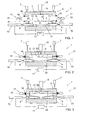
- Fig. 1 shows, in cross-sectional side view, an apparatus 1 to be used with the method according to the invention, provided with a mold 2 with a mold cavity 3 therein.
- the mold comprises a first, moveable part 4 and a second, complementary part 5, fixedly arranged.
- the moveable part 4 is guided by suitable guides, which are not shown but can, for instance, be sliding pins, rails, guide rods or a press or the like and which are directly clear to the skilled person.
- the moveable part is moveable with the aid of devices suitable to that end, represented in Figs. 1-3 as piston-cylinder assemblies 7. It is clear that this may be any suitable device, for instance also a simple press, screw means such as spindles as shown in Fig. 4 , link systems or the like. These can be of relatively light design as they are only meant for moving the part 5, virtually not for absorbing tensile or pressure forces in the further cycle.
- a slide 8 is provided, moveable in the direction S between a retracted position shown in Figs. 1 and 2 , and an extended position shown in Fig. 3 .
- two wedges 9 are provided, to be called wedge-shaped elements, which are moveable in a direction P with the aid of piston-cylinder assemblies 10 which are, for instance, hydraulically driven from a central control unit 11.
- the wedges 9 move in the direction P approximately at right angles to the direction S.
- the slide 8 is provided with two surfaces 12 inclining in opposite directions, complementary to the top surfaces of the wedges 9, such that if the wedges 9 are moved inwards, towards each other, the slide 8 is moved upwards (directions viewed in the plane of the drawing) towards the extended position and vice versa.
- An inflow opening 14 terminates in the mold cavity 3 and is connected to an injection device 15, for instance a plasticizing device and, optionally, a pressing device.
- an injection device 15 for instance a plasticizing device and, optionally, a pressing device.
- flanges 16 are provided which, with the aid of blocking means 17, can be pressed and held onto each other, for keeping the mold closed.
- the blocking means comprise brackets 18 which are moveable with the aid of piston-cylinder assemblies 19 and can be pushed over the flanges 16. In this way, simply, the desired closing pressure can be obtained and maintained.
- two ribs 21 are provided extending over the entire width of the slide 8, at right angles to the plane of drawing.
- the distance D between the end 22 of the ribs leading in the direction of movement, and the oppositely located surface 23 of the mold cavity is set with the slide 8 retracted, depending on the desired product wall thickness and the plastic to be used, while the distance is set to be larger according as the melt of the plastic is higher and/or the melting temperature of the plastic is lower.
- a product can be formed, for instance a sheet with two hinges from thermoplast such as polypropylene or polyethylene, as follows.
- the mold 2 is closed from the position shown in Fig. 1 , as shown in Fig. 2 .
- the distance D is then set at a suitable value, such that the space in the mold cavity 3 is relatively great.
- plastic is introduced into the mold cavity, for instance at a pressure of between 1 and 10 bars excess pressure.
- the filling pressure is selected such that a desired, short feed time is achieved without the material properties of the plastic being adversely affected and without undesirably high pressure occurring in the mold cavity.
- the slide 8 is moved forward, in the direction of the extended position, as shown in Fig. 3 , by moving the wedges 9.
- the speed is selected dependent on the desired adiabatic heat development which should be such that the temperature of the plastic is at least substantially brought back to approximately the melting temperature thereof.
- Plastic that is, possibly, slightly solidified becomes liquid again and can be forced further into the mold so that a complete filling of the mold cavity is obtained while the product can have wall thicknesses which are, in fact, too small for the melt flow index of the respective plastic/product combination.
- some hold pressure can still be given with the aid of the injection device 15, so that undesired stresses can be pressed from the product.
- the mold can be opened again and the product can be taken out.
- the rate of movement of the or each slide is high such that the time of movement of the slide between the retracted and the extended position is relatively short with regard to the cycle time for the manufacture of a product, for instance between 0 and 10% of that time, also depending on the desired adiabatic healing.
- This can be determined by way of an experiment for each plastic-product combination or be calculated with the aid of standard tables regarding plastics, the product properties such as dimensions and flow paths, the friction which will occur when moving the slide and the heat capacity and melt temperature of the plastic.
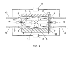
- FIG. 4 an alternative embodiment of an apparatus according to the invention is shown, wherein screw spindles 25 with nut blocks 26 are used for opening and closing the mold 2. These can be wholly or partly included in the mold 2.
- the plastic is introduced via a side inflow opening 14 and a slide 8 is provided on both sides of the mold cavity 3.
- they can be moved independently of each other but it is preferred that they be moved in coupled relation, so that a symmetrical load occurs in the mold 2.
- Table 1 Machine data Machine Stork SX 3000-2150 Machine number X 2936 Year of construction 2000 Main feed 400 V 50 Hz Main current 354 A Control voltage 24 V Max Oil pressure 210 bar Max Air pressure 8 bar Weight closing force 8700 kg Weight Injection force 5000 kg Screw diameter 65 mm
- Table 2 Mold data Length 1050 mm Width 455 mm Height 495mm Number of cavities 1
- Table 3 Produce size Length 655 mm Width 320 mm Thickness 1.7 mm
- an amount of plastic was introduced into the mold cavity, sufficient for manufacturing an end product, in this case a file.
- a shot weight of 128 grams of PP was introduced into the mold cavity.
- the mold cavity comprised a slide with a frontal surface of approximately 200,000 mm 2 , which was moved over a distance of 1.8 mm.
- the plastic was introduced, at a temperature of approximately 245°C at a speed of 750 mm/s, without pressure, at a mold temperature of approximately 50°C, and was cooled down in a first phase to approximately 230 °C.
- the slide was set in motion, which slide was moved completely forwards in approximately 0.4 sec, while the temperature in the mold rose to just below the temperature at which the plastic will decompose.
- the plastic was allowed to cool down to a temperature well below the melting temperature, close to room temperature, for instance 45 to 55°C. This cooling down was done in approximately 12 seconds.
- the product thickness on the covers and the back was on average 1.7 mm by, viewed in frontal surface, 655 mm by 320 mm. During cooling down, the application of hold pressure was not necessary, as a result of the fact that no shrinkage needed to be absorbed. The product appears to be free of stress, so that a high form-stability is obtained.
- the mold was moved with wedges with a wedge angle of approximately 4°.
- the slide is already moved to the extended position while the plastic is being injected into the mold cavity. This also contributes to the plastic being kept in motion.
- Fig. 5 a photographic depiction is given of a CD-box manufactured with a method according to the invention. Here, the flow pattern of the plastic is clearly visible. The photograph is to be explained as follows.
- a mold 2 to be used with the method according to the invention can comprise several mold cavities, while the or each mold cavity can be provided with one or more slides.
- the slides can be driven in different manners, for instance directly instead of by the wedges, and with the aid of different means, for instance electrically.
- the slides can move in different directions, for instance approximately at right angles to the direction of movement of the mold parts, or be pivoted for reducing the space in the mold cavity.
Landscapes
- Engineering & Computer Science (AREA)
- Mechanical Engineering (AREA)
- Manufacturing & Machinery (AREA)
- Moulds For Moulding Plastics Or The Like (AREA)
- Injection Moulding Of Plastics Or The Like (AREA)
- Processing And Handling Of Plastics And Other Materials For Molding In General (AREA)
- Polyesters Or Polycarbonates (AREA)
- Extrusion Moulding Of Plastics Or The Like (AREA)
- Heating, Cooling, Or Curing Plastics Or The Like In General (AREA)
Claims (7)
- Verfahren zum Ausbilden von Kunststoffprodukten, wobei in einen Formgebungshohlraum (3) eine Menge von Kunststoff mit einem Zufuhrdruck von weniger als 350 Bar, vorzugsweise zwischen 0 und 200 Bar in im Wesentlichen plastischen Zustand eingeführt wird, wonach mindestens ein bewegliches Element, welches Schieber (8) genannt wird, zumindest teilweise in den entsprechenden Formgebungshohlraum (3) bewegt wird, während zumindest ein Teil des Kunststoffs gepresst und/oder verlagert wird, wobei die Geschwindigkeit der Bewegung des mindestens einen Schiebers (8) so hoch ist, dass eine adiabatische Hitzeentwicklung in dem Kunststoff auftritt, so dass der Kunststoff flüssiger wird, zumindest seine Viskosität verringert wird und die Temperatur des Kunststoffs zumindest im Wesentlichen auf näherungsweise die Schmelztemperatur davon zurückgebracht wird.
- Verfahren nach Anspruch 1, wobei vor dem Einbringen des Kunststoffs in den Formgebungshohlraum der mindestens eine Schieber auf einen Durchgangsabstand eingestellt wird, welcher durch den Abstand zwischen einem in der Bewegungsrichtung führenden Ende des entsprechenden Schiebers (8) und einem gegenüberliegend angeordneten Wandabschnitt des Formgebungshohlraums bestimmt ist, wobei der Abstand auf der Grundlage des Schmelzens des Kunststoffs, welcher in dem Formgebungshohlraum zu verwenden ist, eingestellt wird.
- Verfahren nach einem der Ansprüche 1-2, wobei der oder jeder Schieber (8) mit einer Geschwindigkeit derart bewegt wird, dass die Bewegung des entsprechenden Schiebers in höchstens ungefähr 20 % der gesamten Zykluszeit eines Herstellungszyklus, welcher durch die Zeit zwischen dem Schließen der Form und dem Entnehmen des fertigen Produkts bestimmt wird, stattfindet.
- Verfahren nach Anspruch 3, wobei die Bewegung des oder jeden Schiebers (8) in weniger als 10 %, insbesondere in weniger als 5 % und vorzugsweise in weniger als 3 % der gesamten Zykluszeit durchgeführt wird.
- Verfahren nach einem der Ansprüche 1-4, wobei als Material ein Kunststoff eingebracht wird, insbesondere ein thermoplastischer Kunststoff, während der Zuführungsdruck und die Zuführungsgeschwindigkeit derart sind, dass zumindest eine teilweise Verfestigung des Kunststoffs während des Einbringens des Kunststoffs auftritt, während der oder jeder Schieber (8) in den Formgebungshohlraum (3) derart gebracht wird, dass darin eine adiabatische Hitzeentwicklung derart stattfindet, dass der Kunststoff in einen flüssigen Zustand zurückkehrt, dass zumindest seine Viskosität derart verringert wird, dass durch Bewegen des Schiebers und optional ein Anwenden eines Haltedrucks der entsprechende Formgebungshohlraum vollständig gefüllt wird.
- Verfahren nach Anspruch 5, wobei in dem oder jedem Formgebungshohlraum (3) Überlaufräume vorgesehen sind, welche mit dem Kunststoff gefüllt werden, wobei die in den Überfüllräumen gefüllten Teile als Eingriffselemente zum Entnehmen eines in dem entsprechenden Formgebungshohlraum ausgebildeten Produkts verwendet werden.
- Verfahren nach einem der Ansprüche 1-6, wobei ein Formgebungshohlraum verwendet wird, welcher mindestens ein Formgebungsteil zum Ausbilden eines dünnwandigen Produktteils umfasst, während mindestens ein Schieber (8) in oder benachbart zu dem Formgebungsteil vorgesehen ist und eine Bewegungsrichtung aufweist, welche einen Winkel mit einer Ebene parallel zu der dünnen Wanddicke des Produktteils einschließt, insbesondere einen Winkel zwischen 30 und 90°, während das produktformgebende Teil mit dem Schieber (8) in einer ersten zurückgezogenen Position einen verhältnismäßig großen Durchgang definiert und in einer zweiten ausgebreiteten Position einen Durchgang definiert, welcher dem Querschnitt des auszubildenden dünnwandigen Produktteils entspricht, wobei der Durchgang mit dem Schieber in der zweiten Position zumindest teilweise kleiner als ein passender Schmelzindex (Melt-Flow Index, MFI) des Kunststoffs, welcher während einer Verwendung einzubringen ist, ist, während der Durchgang mit dem Schieber (8) in der ersten Position erheblich größer als der passende MFI ist.
Priority Applications (1)
| Application Number | Priority Date | Filing Date | Title |
|---|---|---|---|
| EP08172917A EP2033761A1 (de) | 2002-09-10 | 2003-09-10 | Vorrichtung und Verfahren zum Herstellen von Gegenständen aus thermoplastischer Masse |
Applications Claiming Priority (3)
| Application Number | Priority Date | Filing Date | Title |
|---|---|---|---|
| NL1021421 | 2002-09-10 | ||
| NL1021421A NL1021421C2 (nl) | 2002-09-10 | 2002-09-10 | Inrichting en werkwijze voor het vervaardigen van producten uit een warm plastische massa. |
| PCT/NL2003/000630 WO2004024416A1 (en) | 2002-09-10 | 2003-09-10 | Apparatus and method for manufacturing products from a thermoplastic mass |
Related Child Applications (1)
| Application Number | Title | Priority Date | Filing Date |
|---|---|---|---|
| EP08172917A Division EP2033761A1 (de) | 2002-09-10 | 2003-09-10 | Vorrichtung und Verfahren zum Herstellen von Gegenständen aus thermoplastischer Masse |
Publications (2)
| Publication Number | Publication Date |
|---|---|
| EP1560694A1 EP1560694A1 (de) | 2005-08-10 |
| EP1560694B1 true EP1560694B1 (de) | 2009-02-25 |
Family
ID=31987577
Family Applications (2)
| Application Number | Title | Priority Date | Filing Date |
|---|---|---|---|
| EP03795499A Expired - Lifetime EP1560694B1 (de) | 2002-09-10 | 2003-09-10 | Verfahren zur herstellung von produkten aus einer thermoplastischen masse |
| EP08172917A Withdrawn EP2033761A1 (de) | 2002-09-10 | 2003-09-10 | Vorrichtung und Verfahren zum Herstellen von Gegenständen aus thermoplastischer Masse |
Family Applications After (1)
| Application Number | Title | Priority Date | Filing Date |
|---|---|---|---|
| EP08172917A Withdrawn EP2033761A1 (de) | 2002-09-10 | 2003-09-10 | Vorrichtung und Verfahren zum Herstellen von Gegenständen aus thermoplastischer Masse |
Country Status (13)
| Country | Link |
|---|---|
| US (3) | US7504059B2 (de) |
| EP (2) | EP1560694B1 (de) |
| JP (1) | JP2005537958A (de) |
| CN (2) | CN1705552B (de) |
| AT (1) | ATE423668T1 (de) |
| AU (1) | AU2003263668A1 (de) |
| CA (1) | CA2512578C (de) |
| DE (1) | DE60326372D1 (de) |
| DK (1) | DK1560694T3 (de) |
| ES (1) | ES2323171T3 (de) |
| NL (2) | NL1021421C2 (de) |
| PT (1) | PT1560694E (de) |
| WO (1) | WO2004024416A1 (de) |
Families Citing this family (25)
| Publication number | Priority date | Publication date | Assignee | Title |
|---|---|---|---|---|
| JP4659300B2 (ja) * | 2000-09-13 | 2011-03-30 | 浜松ホトニクス株式会社 | レーザ加工方法及び半導体チップの製造方法 |
| NL1023365C2 (nl) * | 2003-05-08 | 2004-11-09 | Fountain Patents B V | Werkwijze en inrichting voor het vervaardigen van voertuigonderdelen. |
| US7293981B2 (en) * | 2004-04-23 | 2007-11-13 | Husky Injection Molding Systems Ltd. | Apparatus for injection molding using active material elements |
| NL1027261C2 (nl) * | 2004-10-15 | 2006-04-24 | Ecim Technologies Bv | Inrichting en werkwijze voor het vervaardigen van kunststof producten. |
| NL1027638C2 (nl) * | 2004-12-01 | 2006-06-02 | Ecim Technologies Bv | Informatiedrager en werkwijze en inrichting voor de vervaardiging daarvan. |
| JP2008522875A (ja) | 2004-12-07 | 2008-07-03 | スリーエム イノベイティブ プロパティズ カンパニー | マイクロニードルの成形方法 |
| US7687003B2 (en) * | 2004-12-08 | 2010-03-30 | Visteon Global Technologies, Inc. | Method of forming plastic part having hidden thin walled section |
| NL1027910C2 (nl) * | 2004-12-28 | 2006-06-29 | Ecim Technologies Bv | Werkwijze en inrichting voor de vervaardiging van producten. |
| JP4923924B2 (ja) | 2005-11-22 | 2012-04-25 | コニカミノルタホールディングス株式会社 | インプリント装置及びインプリント方法 |
| NL1032248C2 (nl) | 2006-07-28 | 2008-01-29 | Ecim Technologies Bv | Werkwijze en inrichting voor het vervaardigen van producten. |
| NL1032947C2 (nl) * | 2006-11-27 | 2008-05-28 | Ecim Technologies Bv | Inrichting en werkwijze voor de vorming van producten. |
| EP2145746A1 (de) | 2008-07-16 | 2010-01-20 | I-Pac Patents B.V. | Verfahren zur Herstellung einer Kunststoffverpackung in einer Form |
| PL2346664T3 (pl) | 2008-09-15 | 2013-04-30 | Tacx Onroerend En Roerend Goed B V | Przyrząd i sposób regulowania wtryskowego formowania tłocznego |
| CN101774256B (zh) * | 2009-12-29 | 2012-10-17 | 广州毅昌科技股份有限公司 | 一种压缩注塑成型机及其使用方法 |
| US8974224B2 (en) * | 2011-03-08 | 2015-03-10 | Craig M. Stanley | Position-locking apparatus for insert and over molding of delicate components |
| JP2012250510A (ja) * | 2011-06-06 | 2012-12-20 | Seiko Epson Corp | 射出成形金型、射出成形品及び射出成形方法 |
| WO2014117246A1 (en) * | 2013-02-01 | 2014-08-07 | Husky Injection Molding Systems Ltd. | Molding system having an adjustable mold shut height |
| NL2011765C2 (nl) | 2013-11-08 | 2015-05-19 | Vitaplus Nederland B V | Inrichting en werkwijze voor het begrenzen van de hoeveelheid fluïdum. |
| FR3029446B1 (fr) * | 2014-12-05 | 2017-01-13 | Plastic Omnium Cie | Moule pour la fabrication de piece en matiere plastique comportant un systeme pour realiser des orifices dans la piece |
| GB2544717B (en) * | 2015-09-25 | 2019-04-10 | Gr8 Eng Ltd | Injection Molding Method |
| CN106273206B (zh) * | 2016-08-18 | 2019-01-01 | 天津华夏联盛汽车部件有限公司 | 一种前保险杠面罩注塑加工工艺 |
| DE102016119636B3 (de) * | 2016-10-14 | 2018-02-08 | Carl Zeiss Smart Optics Gmbh | Abformwerkzeug und Verwendung desselben |
| JP7163911B2 (ja) * | 2018-03-30 | 2022-11-01 | 東レ株式会社 | プレス成形品の製造方法 |
| CN109049546A (zh) * | 2018-07-16 | 2018-12-21 | 温州职业技术学院 | 一种型腔高度可调式注塑模具 |
| CN111703026A (zh) * | 2020-07-20 | 2020-09-25 | 漳州市吉盛精密模具有限公司 | 一种塑胶环快速成型的塑胶模具 |
Family Cites Families (33)
| Publication number | Priority date | Publication date | Assignee | Title |
|---|---|---|---|---|
| US3208105A (en) * | 1962-04-13 | 1965-09-28 | Charles S White | Molding press |
| US3195186A (en) * | 1962-06-13 | 1965-07-20 | Inv S Finance Corp | Apparatus for clamping mold parts |
| US4184835A (en) * | 1978-09-28 | 1980-01-22 | General Electric Company | Mold apparatus |
| JPS58211424A (ja) * | 1982-06-02 | 1983-12-08 | Ricoh Co Ltd | 射出圧縮成形機 |
| FR2545033B1 (fr) * | 1983-04-28 | 1985-08-16 | Cibie Projecteurs | Procede et dispositif pour la realisation de pieces en matiere plastique, sur presse a injection |
| US4778632A (en) * | 1986-01-06 | 1988-10-18 | Neolens, Inc. | Injection molding equipment and method |
| DE3718106A1 (de) * | 1987-05-27 | 1988-12-15 | Mannesmann Ag | Praezisionsschliesseinheit fuer eine spritzgiessmaschine |
| US4980115A (en) * | 1987-05-28 | 1990-12-25 | Yoshida Industry Co. Ltd. | Method for making an injection-molded product having a partly thin portion |
| US5049344A (en) * | 1988-06-02 | 1991-09-17 | Primtec | Method for reducing required mold-cavity clamping force and controlling injection-molded-product wall thickness |
| EP0425060B1 (de) * | 1989-10-27 | 1995-08-23 | Mitsubishi Jukogyo Kabushiki Kaisha | Verfahren zum Spritzgiessen und Vorrichtung dafür |
| JPH03161317A (ja) * | 1989-11-21 | 1991-07-11 | Toshiba Corp | 射出圧縮成形用金型 |
| TW205018B (de) * | 1990-11-30 | 1993-05-01 | Toshiba Machine Co Ltd | |
| JPH04263916A (ja) * | 1991-02-20 | 1992-09-18 | Toshiba Corp | 成形装置 |
| JPH05261779A (ja) * | 1991-07-15 | 1993-10-12 | Komatsu Ltd | 射出成形機の射出圧縮成形方法 |
| JPH0615711A (ja) * | 1992-04-08 | 1994-01-25 | Dr Spiess Kunststoff Recycling Gmbh & Co | 合成物質、特にリサイクル合成物質から資材を自動的に造るための方法および装置 |
| JPH06126791A (ja) * | 1992-10-21 | 1994-05-10 | Toyo Mach & Metal Co Ltd | 射出成形機の圧縮力制御方法 |
| JPH06126790A (ja) * | 1992-10-21 | 1994-05-10 | Toyo Mach & Metal Co Ltd | 射出圧縮成形機の圧縮制御方法 |
| US5424017A (en) * | 1993-04-12 | 1995-06-13 | Hinduja; Murli L. | Method for forming fiber-reinforced articles |
| JPH06328489A (ja) * | 1993-05-24 | 1994-11-29 | Japan Steel Works Ltd:The | 射出プレス成形方法及び装置 |
| JP3331680B2 (ja) * | 1993-07-13 | 2002-10-07 | アイシン精機株式会社 | サンドイッチ成形品の製造方法及び成形装置 |
| GB2282560B (en) * | 1993-09-14 | 1997-12-17 | Idemitsu Petrochemical Co | Compression equipment of injection compression molding machine and injection compression molding machine |
| JPH0885285A (ja) * | 1994-07-21 | 1996-04-02 | Hitachi Maxell Ltd | セキュリティカード用基板の製造方法、およびセキュリティカード用基板 |
| US5993719A (en) * | 1994-09-08 | 1999-11-30 | Idemitsu Petrochemical Co., Ltd. | Method of producing a laminated molding |
| US5512221A (en) * | 1994-12-22 | 1996-04-30 | Galic Maus Ventures | Lens thickness adjustment method and apparatus in a thermoplastic injection mold for ophthalmic finished spectacle lenses |
| JP3300562B2 (ja) * | 1995-03-14 | 2002-07-08 | 出光石油化学株式会社 | 射出圧縮成形方法及び射出圧縮成形装置 |
| WO1997029896A1 (en) * | 1996-02-16 | 1997-08-21 | Idemitsu Petrochemical Co., Ltd. | A method of forming a light-weight, fiber-reinforced thermoplastic resin product and a light-weight molded product |
| US6248281B1 (en) * | 1996-11-14 | 2001-06-19 | Idemitsu Petrochemical Co., Ltd. | Compression apparatus for molding, injection compression molding machine, and injection compression molding method using the compression device |
| JP3943696B2 (ja) * | 1998-03-11 | 2007-07-11 | 株式会社プライムポリマー | 積層成形品の製造方法 |
| JP4146026B2 (ja) * | 1998-04-24 | 2008-09-03 | 株式会社プライムポリマー | 成形装置及び成形方法 |
| US6267580B1 (en) | 1998-11-02 | 2001-07-31 | Murray Incorporated | Micro injection molding machine |
| JP2002096356A (ja) * | 2000-09-22 | 2002-04-02 | Honda Motor Co Ltd | 射出圧縮成形型 |
| DE10113224A1 (de) * | 2001-03-19 | 2002-10-02 | Ap & T Schaefer Technologie Gm | Schließeinheit für gegen aufgehende Kräfte zusammenzupressende Werkzeuge |
| AUPR393001A0 (en) * | 2001-03-23 | 2001-04-26 | Sola International Holdings Ltd | Injection molding method |
-
2002
- 2002-09-10 NL NL1021421A patent/NL1021421C2/nl not_active IP Right Cessation
-
2003
- 2003-09-10 DE DE60326372T patent/DE60326372D1/de not_active Expired - Lifetime
- 2003-09-10 CN CN03824756.9A patent/CN1705552B/zh not_active Expired - Fee Related
- 2003-09-10 CA CA2512578A patent/CA2512578C/en not_active Expired - Fee Related
- 2003-09-10 JP JP2004535279A patent/JP2005537958A/ja active Pending
- 2003-09-10 EP EP03795499A patent/EP1560694B1/de not_active Expired - Lifetime
- 2003-09-10 AU AU2003263668A patent/AU2003263668A1/en not_active Abandoned
- 2003-09-10 AT AT03795499T patent/ATE423668T1/de active
- 2003-09-10 EP EP08172917A patent/EP2033761A1/de not_active Withdrawn
- 2003-09-10 CN CN201010124834A patent/CN101863109A/zh active Pending
- 2003-09-10 ES ES03795499T patent/ES2323171T3/es not_active Expired - Lifetime
- 2003-09-10 PT PT03795499T patent/PT1560694E/pt unknown
- 2003-09-10 US US10/527,364 patent/US7504059B2/en not_active Expired - Fee Related
- 2003-09-10 NL NL1024263A patent/NL1024263C2/nl not_active IP Right Cessation
- 2003-09-10 DK DK03795499T patent/DK1560694T3/da active
- 2003-09-10 WO PCT/NL2003/000630 patent/WO2004024416A1/en not_active Ceased
-
2009
- 2009-01-21 US US12/321,425 patent/US7891970B2/en not_active Expired - Fee Related
-
2011
- 2011-02-01 US US13/018,960 patent/US8360769B2/en not_active Expired - Fee Related
Also Published As
| Publication number | Publication date |
|---|---|
| US8360769B2 (en) | 2013-01-29 |
| US20090194909A1 (en) | 2009-08-06 |
| ATE423668T1 (de) | 2009-03-15 |
| PT1560694E (pt) | 2009-06-01 |
| ES2323171T3 (es) | 2009-07-08 |
| CN1705552B (zh) | 2010-05-05 |
| DE60326372D1 (de) | 2009-04-09 |
| WO2004024416A1 (en) | 2004-03-25 |
| CN1705552A (zh) | 2005-12-07 |
| US7891970B2 (en) | 2011-02-22 |
| NL1024263C2 (nl) | 2004-03-16 |
| CN101863109A (zh) | 2010-10-20 |
| JP2005537958A (ja) | 2005-12-15 |
| DK1560694T3 (da) | 2009-06-15 |
| US7504059B2 (en) | 2009-03-17 |
| EP1560694A1 (de) | 2005-08-10 |
| US20110123662A1 (en) | 2011-05-26 |
| US20060033228A1 (en) | 2006-02-16 |
| AU2003263668A1 (en) | 2004-04-30 |
| WO2004024416A8 (en) | 2005-06-09 |
| NL1021421C2 (nl) | 2004-03-11 |
| CA2512578C (en) | 2015-05-26 |
| CA2512578A1 (en) | 2004-03-25 |
| EP2033761A1 (de) | 2009-03-11 |
Similar Documents
| Publication | Publication Date | Title |
|---|---|---|
| EP1560694B1 (de) | Verfahren zur herstellung von produkten aus einer thermoplastischen masse | |
| US5922266A (en) | Injection molding | |
| EP0172536B1 (de) | Verfahren zum Spritzgiessen für geschmolzenen Kunststoff | |
| NL1028066C2 (nl) | Werkwijze en inrichting voor de vervaardiging van gelabelde kunststof producten. | |
| NL1027076C2 (nl) | Inrichting en werkwijze voor het vervaardigen van kunststof producten. | |
| NL1027261C2 (nl) | Inrichting en werkwijze voor het vervaardigen van kunststof producten. | |
| EP4091738B1 (de) | Vorrichtung und verfahren zm formen von material | |
| CN120480139A (zh) | 压铸机及基于压铸机的压铸法 | |
| EP1912773B1 (de) | Verfahren, steuerung für eine maschine und computerprogrammprodukt zur steuerung einer maschine zur herstellung eines formteils, insbesondere spritzgiessverfahren | |
| JPH0490322A (ja) | 射出圧縮成形方法 | |
| RU2455159C2 (ru) | Способ и устройство для получения формованных изделий из термопластичных материалов литьем под давлением | |
| JP3151412B2 (ja) | 樹脂成形装置 | |
| JP3011097U (ja) | 射出成形装置 | |
| JP2553868Y2 (ja) | 薄肉樹脂平板の射出成形型 | |
| JPH11105084A (ja) | 射出成形金型装置及びそれを用いた射出成形方法 | |
| JP4565819B2 (ja) | 厚肉長尺品の射出成形方法および射出成形用金型 | |
| JPH06305746A (ja) | 光学ガラスレンズ用成形型 | |
| JPH01118422A (ja) | 射出圧縮成形金型 | |
| JPH05261779A (ja) | 射出成形機の射出圧縮成形方法 | |
| JPH01145116A (ja) | 樹脂成形用多段金型 | |
| JPH05116193A (ja) | 射出成形法 | |
| JPH04189520A (ja) | 射出成形用金型 |
Legal Events
| Date | Code | Title | Description |
|---|---|---|---|
| PUAI | Public reference made under article 153(3) epc to a published international application that has entered the european phase |
Free format text: ORIGINAL CODE: 0009012 |
|
| 17P | Request for examination filed |
Effective date: 20050311 |
|
| AK | Designated contracting states |
Kind code of ref document: A1 Designated state(s): AT BE BG CH CY CZ DE DK EE ES FI FR GB GR HU IE IT LI LU MC NL PT RO SE SI SK TR |
|
| AX | Request for extension of the european patent |
Extension state: AL LT LV MK |
|
| DAX | Request for extension of the european patent (deleted) | ||
| RAP1 | Party data changed (applicant data changed or rights of an application transferred) |
Owner name: ECIM TECHNOLOGIES B.V. |
|
| RAP1 | Party data changed (applicant data changed or rights of an application transferred) |
Owner name: ECIM TECHNOLOGIES B.V. |
|
| 17Q | First examination report despatched |
Effective date: 20050915 |
|
| GRAP | Despatch of communication of intention to grant a patent |
Free format text: ORIGINAL CODE: EPIDOSNIGR1 |
|
| RTI1 | Title (correction) |
Free format text: METHOD FOR MANUFACTURING PRODUCTS FROM A THERMOPLASTIC MASS |
|
| GRAS | Grant fee paid |
Free format text: ORIGINAL CODE: EPIDOSNIGR3 |
|
| GRAA | (expected) grant |
Free format text: ORIGINAL CODE: 0009210 |
|
| AK | Designated contracting states |
Kind code of ref document: B1 Designated state(s): AT BE BG CH CY CZ DE DK EE ES FI FR GB GR HU IE IT LI LU MC NL PT RO SE SI SK TR |
|
| REG | Reference to a national code |
Ref country code: GB Ref legal event code: FG4D |
|
| REG | Reference to a national code |
Ref country code: CH Ref legal event code: EP |
|
| REG | Reference to a national code |
Ref country code: IE Ref legal event code: FG4D |
|
| REF | Corresponds to: |
Ref document number: 60326372 Country of ref document: DE Date of ref document: 20090409 Kind code of ref document: P |
|
| REG | Reference to a national code |
Ref country code: RO Ref legal event code: EPE |
|
| REG | Reference to a national code |
Ref country code: PT Ref legal event code: SC4A Free format text: AVAILABILITY OF NATIONAL TRANSLATION Effective date: 20090522 |
|
| REG | Reference to a national code |
Ref country code: SE Ref legal event code: TRGR |
|
| REG | Reference to a national code |
Ref country code: DK Ref legal event code: T3 Ref country code: CH Ref legal event code: NV Representative=s name: R. A. EGLI & CO. PATENTANWAELTE |
|
| REG | Reference to a national code |
Ref country code: ES Ref legal event code: FG2A Ref document number: 2323171 Country of ref document: ES Kind code of ref document: T3 |
|
| PG25 | Lapsed in a contracting state [announced via postgrant information from national office to epo] |
Ref country code: SI Free format text: LAPSE BECAUSE OF FAILURE TO SUBMIT A TRANSLATION OF THE DESCRIPTION OR TO PAY THE FEE WITHIN THE PRESCRIBED TIME-LIMIT Effective date: 20090225 |
|
| PG25 | Lapsed in a contracting state [announced via postgrant information from national office to epo] |
Ref country code: EE Free format text: LAPSE BECAUSE OF FAILURE TO SUBMIT A TRANSLATION OF THE DESCRIPTION OR TO PAY THE FEE WITHIN THE PRESCRIBED TIME-LIMIT Effective date: 20090225 |
|
| PGFP | Annual fee paid to national office [announced via postgrant information from national office to epo] |
Ref country code: DK Payment date: 20090910 Year of fee payment: 7 Ref country code: ES Payment date: 20090924 Year of fee payment: 7 Ref country code: IE Payment date: 20090921 Year of fee payment: 7 |
|
| PG25 | Lapsed in a contracting state [announced via postgrant information from national office to epo] |
Ref country code: SK Free format text: LAPSE BECAUSE OF FAILURE TO SUBMIT A TRANSLATION OF THE DESCRIPTION OR TO PAY THE FEE WITHIN THE PRESCRIBED TIME-LIMIT Effective date: 20090225 |
|
| PGFP | Annual fee paid to national office [announced via postgrant information from national office to epo] |
Ref country code: FI Payment date: 20090915 Year of fee payment: 7 Ref country code: HU Payment date: 20090930 Year of fee payment: 7 Ref country code: RO Payment date: 20090907 Year of fee payment: 7 Ref country code: SE Payment date: 20090915 Year of fee payment: 7 Ref country code: TR Payment date: 20090909 Year of fee payment: 7 |
|
| PLBI | Opposition filed |
Free format text: ORIGINAL CODE: 0009260 |
|
| 26 | Opposition filed |
Opponent name: IPX INTERNATIONAL B.V. Effective date: 20091125 |
|
| PLAX | Notice of opposition and request to file observation + time limit sent |
Free format text: ORIGINAL CODE: EPIDOSNOBS2 |
|
| REG | Reference to a national code |
Ref country code: HU Ref legal event code: AG4A Ref document number: E006248 Country of ref document: HU |
|
| PG25 | Lapsed in a contracting state [announced via postgrant information from national office to epo] |
Ref country code: BG Free format text: LAPSE BECAUSE OF FAILURE TO SUBMIT A TRANSLATION OF THE DESCRIPTION OR TO PAY THE FEE WITHIN THE PRESCRIBED TIME-LIMIT Effective date: 20090525 |
|
| PGFP | Annual fee paid to national office [announced via postgrant information from national office to epo] |
Ref country code: BE Payment date: 20090911 Year of fee payment: 7 |
|
| NLR1 | Nl: opposition has been filed with the epo |
Opponent name: IPX INTERNATIONAL B.V. |
|
| PG25 | Lapsed in a contracting state [announced via postgrant information from national office to epo] |
Ref country code: MC Free format text: LAPSE BECAUSE OF NON-PAYMENT OF DUE FEES Effective date: 20090930 |
|
| PLAF | Information modified related to communication of a notice of opposition and request to file observations + time limit |
Free format text: ORIGINAL CODE: EPIDOSCOBS2 |
|
| PLAF | Information modified related to communication of a notice of opposition and request to file observations + time limit |
Free format text: ORIGINAL CODE: EPIDOSCOBS2 |
|
| PLBP | Opposition withdrawn |
Free format text: ORIGINAL CODE: 0009264 |
|
| PLBD | Termination of opposition procedure: decision despatched |
Free format text: ORIGINAL CODE: EPIDOSNOPC1 |
|
| PG25 | Lapsed in a contracting state [announced via postgrant information from national office to epo] |
Ref country code: GR Free format text: LAPSE BECAUSE OF FAILURE TO SUBMIT A TRANSLATION OF THE DESCRIPTION OR TO PAY THE FEE WITHIN THE PRESCRIBED TIME-LIMIT Effective date: 20090526 |
|
| PGFP | Annual fee paid to national office [announced via postgrant information from national office to epo] |
Ref country code: CZ Payment date: 20100910 Year of fee payment: 8 |
|
| PGFP | Annual fee paid to national office [announced via postgrant information from national office to epo] |
Ref country code: PT Payment date: 20100909 Year of fee payment: 8 |
|
| PLBM | Termination of opposition procedure: date of legal effect published |
Free format text: ORIGINAL CODE: 0009276 |
|
| STAA | Information on the status of an ep patent application or granted ep patent |
Free format text: STATUS: OPPOSITION PROCEDURE CLOSED |
|
| 27C | Opposition proceedings terminated |
Effective date: 20101008 |
|
| BERE | Be: lapsed |
Owner name: ECIM TECHNOLOGIES B.V. Effective date: 20100930 |
|
| PG25 | Lapsed in a contracting state [announced via postgrant information from national office to epo] |
Ref country code: LU Free format text: LAPSE BECAUSE OF NON-PAYMENT OF DUE FEES Effective date: 20090910 |
|
| REG | Reference to a national code |
Ref country code: SE Ref legal event code: EUG |
|
| REG | Reference to a national code |
Ref country code: DK Ref legal event code: EBP |
|
| PG25 | Lapsed in a contracting state [announced via postgrant information from national office to epo] |
Ref country code: FI Free format text: LAPSE BECAUSE OF NON-PAYMENT OF DUE FEES Effective date: 20100910 |
|
| PG25 | Lapsed in a contracting state [announced via postgrant information from national office to epo] |
Ref country code: HU Free format text: LAPSE BECAUSE OF NON-PAYMENT OF DUE FEES Effective date: 20100911 Ref country code: BE Free format text: LAPSE BECAUSE OF NON-PAYMENT OF DUE FEES Effective date: 20100930 Ref country code: IE Free format text: LAPSE BECAUSE OF NON-PAYMENT OF DUE FEES Effective date: 20100910 |
|
| PG25 | Lapsed in a contracting state [announced via postgrant information from national office to epo] |
Ref country code: CY Free format text: LAPSE BECAUSE OF FAILURE TO SUBMIT A TRANSLATION OF THE DESCRIPTION OR TO PAY THE FEE WITHIN THE PRESCRIBED TIME-LIMIT Effective date: 20090225 |
|
| REG | Reference to a national code |
Ref country code: ES Ref legal event code: FD2A Effective date: 20111019 |
|
| PG25 | Lapsed in a contracting state [announced via postgrant information from national office to epo] |
Ref country code: DK Free format text: LAPSE BECAUSE OF NON-PAYMENT OF DUE FEES Effective date: 20100930 |
|
| PG25 | Lapsed in a contracting state [announced via postgrant information from national office to epo] |
Ref country code: RO Free format text: LAPSE BECAUSE OF NON-PAYMENT OF DUE FEES Effective date: 20100910 Ref country code: ES Free format text: LAPSE BECAUSE OF NON-PAYMENT OF DUE FEES Effective date: 20100911 |
|
| REG | Reference to a national code |
Ref country code: PT Ref legal event code: MM4A Free format text: LAPSE DUE TO NON-PAYMENT OF FEES Effective date: 20120312 |
|
| PG25 | Lapsed in a contracting state [announced via postgrant information from national office to epo] |
Ref country code: CZ Free format text: LAPSE BECAUSE OF NON-PAYMENT OF DUE FEES Effective date: 20110910 |
|
| PG25 | Lapsed in a contracting state [announced via postgrant information from national office to epo] |
Ref country code: PT Free format text: LAPSE BECAUSE OF NON-PAYMENT OF DUE FEES Effective date: 20120312 Ref country code: IT Free format text: LAPSE BECAUSE OF NON-PAYMENT OF DUE FEES Effective date: 20110910 |
|
| PG25 | Lapsed in a contracting state [announced via postgrant information from national office to epo] |
Ref country code: SE Free format text: LAPSE BECAUSE OF NON-PAYMENT OF DUE FEES Effective date: 20100911 |
|
| PGFP | Annual fee paid to national office [announced via postgrant information from national office to epo] |
Ref country code: IT Payment date: 20120330 Year of fee payment: 9 |
|
| PGRI | Patent reinstated in contracting state [announced from national office to epo] |
Ref country code: IT Effective date: 20120630 |
|
| PG25 | Lapsed in a contracting state [announced via postgrant information from national office to epo] |
Ref country code: TR Free format text: LAPSE BECAUSE OF NON-PAYMENT OF DUE FEES Effective date: 20100910 |
|
| PGFP | Annual fee paid to national office [announced via postgrant information from national office to epo] |
Ref country code: DE Payment date: 20130328 Year of fee payment: 10 Ref country code: CH Payment date: 20130326 Year of fee payment: 10 Ref country code: GB Payment date: 20130328 Year of fee payment: 10 |
|
| PGFP | Annual fee paid to national office [announced via postgrant information from national office to epo] |
Ref country code: AT Payment date: 20130327 Year of fee payment: 10 |
|
| PGFP | Annual fee paid to national office [announced via postgrant information from national office to epo] |
Ref country code: NL Payment date: 20130328 Year of fee payment: 10 Ref country code: FR Payment date: 20130429 Year of fee payment: 10 |
|
| REG | Reference to a national code |
Ref country code: NL Ref legal event code: V1 Effective date: 20140401 |
|
| REG | Reference to a national code |
Ref country code: CH Ref legal event code: PL |
|
| REG | Reference to a national code |
Ref country code: AT Ref legal event code: MM01 Ref document number: 423668 Country of ref document: AT Kind code of ref document: T Effective date: 20130910 |
|
| GBPC | Gb: european patent ceased through non-payment of renewal fee |
Effective date: 20130910 |
|
| REG | Reference to a national code |
Ref country code: DE Ref legal event code: R119 Ref document number: 60326372 Country of ref document: DE Effective date: 20140401 |
|
| REG | Reference to a national code |
Ref country code: FR Ref legal event code: ST Effective date: 20140530 |
|
| PG25 | Lapsed in a contracting state [announced via postgrant information from national office to epo] |
Ref country code: CH Free format text: LAPSE BECAUSE OF NON-PAYMENT OF DUE FEES Effective date: 20130930 Ref country code: LI Free format text: LAPSE BECAUSE OF NON-PAYMENT OF DUE FEES Effective date: 20130930 Ref country code: GB Free format text: LAPSE BECAUSE OF NON-PAYMENT OF DUE FEES Effective date: 20130910 |
|
| PG25 | Lapsed in a contracting state [announced via postgrant information from national office to epo] |
Ref country code: IT Free format text: LAPSE BECAUSE OF NON-PAYMENT OF DUE FEES Effective date: 20130910 Ref country code: DE Free format text: LAPSE BECAUSE OF NON-PAYMENT OF DUE FEES Effective date: 20140401 Ref country code: FR Free format text: LAPSE BECAUSE OF NON-PAYMENT OF DUE FEES Effective date: 20130930 Ref country code: AT Free format text: LAPSE BECAUSE OF NON-PAYMENT OF DUE FEES Effective date: 20130910 Ref country code: NL Free format text: LAPSE BECAUSE OF NON-PAYMENT OF DUE FEES Effective date: 20140401 |