EP1560694B1 - Method for manufacturing products from a thermoplastic mass - Google Patents
Method for manufacturing products from a thermoplastic mass Download PDFInfo
- Publication number
- EP1560694B1 EP1560694B1 EP03795499A EP03795499A EP1560694B1 EP 1560694 B1 EP1560694 B1 EP 1560694B1 EP 03795499 A EP03795499 A EP 03795499A EP 03795499 A EP03795499 A EP 03795499A EP 1560694 B1 EP1560694 B1 EP 1560694B1
- Authority
- EP
- European Patent Office
- Prior art keywords
- plastic
- slide
- mold cavity
- mold
- movement
- Prior art date
- Legal status (The legal status is an assumption and is not a legal conclusion. Google has not performed a legal analysis and makes no representation as to the accuracy of the status listed.)
- Expired - Lifetime
Links
- 238000000034 method Methods 0.000 title claims abstract description 38
- 238000004519 manufacturing process Methods 0.000 title claims abstract description 8
- 229920001169 thermoplastic Polymers 0.000 title claims description 3
- 239000004416 thermosoftening plastic Substances 0.000 title 1
- 239000004033 plastic Substances 0.000 claims abstract description 92
- 229920003023 plastic Polymers 0.000 claims abstract description 92
- 239000000463 material Substances 0.000 claims abstract description 42
- 238000011161 development Methods 0.000 claims abstract description 10
- 239000007788 liquid Substances 0.000 claims abstract description 6
- 230000003247 decreasing effect Effects 0.000 claims abstract 2
- 238000002844 melting Methods 0.000 claims description 7
- 230000008018 melting Effects 0.000 claims description 7
- 239000000155 melt Substances 0.000 claims description 6
- 238000007711 solidification Methods 0.000 claims description 5
- 230000008023 solidification Effects 0.000 claims description 5
- 238000000605 extraction Methods 0.000 claims 1
- 239000007924 injection Substances 0.000 abstract description 22
- 238000002347 injection Methods 0.000 abstract description 22
- 238000001746 injection moulding Methods 0.000 abstract description 14
- 239000000047 product Substances 0.000 description 43
- 238000001816 cooling Methods 0.000 description 4
- 239000004743 Polypropylene Substances 0.000 description 3
- 238000000429 assembly Methods 0.000 description 3
- 230000000712 assembly Effects 0.000 description 3
- 230000000903 blocking effect Effects 0.000 description 3
- 238000000465 moulding Methods 0.000 description 3
- -1 polypropylene Polymers 0.000 description 3
- 230000002411 adverse Effects 0.000 description 2
- 230000000295 complement effect Effects 0.000 description 2
- 230000006835 compression Effects 0.000 description 2
- 238000007906 compression Methods 0.000 description 2
- 230000001419 dependent effect Effects 0.000 description 2
- 238000006073 displacement reaction Methods 0.000 description 2
- 238000002474 experimental method Methods 0.000 description 2
- 230000002349 favourable effect Effects 0.000 description 2
- 229920001155 polypropylene Polymers 0.000 description 2
- VQDBNKDJNJQRDG-UHFFFAOYSA-N Pirbuterol Chemical compound CC(C)(C)NCC(O)C1=CC=C(O)C(CO)=N1 VQDBNKDJNJQRDG-UHFFFAOYSA-N 0.000 description 1
- 239000004698 Polyethylene Substances 0.000 description 1
- 230000006978 adaptation Effects 0.000 description 1
- 238000005273 aeration Methods 0.000 description 1
- 238000013459 approach Methods 0.000 description 1
- 230000015572 biosynthetic process Effects 0.000 description 1
- 239000007795 chemical reaction product Substances 0.000 description 1
- 238000005352 clarification Methods 0.000 description 1
- 239000003086 colorant Substances 0.000 description 1
- 238000000748 compression moulding Methods 0.000 description 1
- 238000010276 construction Methods 0.000 description 1
- 230000006837 decompression Effects 0.000 description 1
- 238000013461 design Methods 0.000 description 1
- 238000009826 distribution Methods 0.000 description 1
- 230000000694 effects Effects 0.000 description 1
- 230000035876 healing Effects 0.000 description 1
- 229940103178 maxair Drugs 0.000 description 1
- 239000000178 monomer Substances 0.000 description 1
- 229920000573 polyethylene Polymers 0.000 description 1
- 229920000642 polymer Polymers 0.000 description 1
- 238000003825 pressing Methods 0.000 description 1
- 238000000926 separation method Methods 0.000 description 1
- 239000012899 standard injection Substances 0.000 description 1
- 239000000126 substance Substances 0.000 description 1
- 239000012815 thermoplastic material Substances 0.000 description 1
Images
Classifications
-
- B—PERFORMING OPERATIONS; TRANSPORTING
- B29—WORKING OF PLASTICS; WORKING OF SUBSTANCES IN A PLASTIC STATE IN GENERAL
- B29C—SHAPING OR JOINING OF PLASTICS; SHAPING OF MATERIAL IN A PLASTIC STATE, NOT OTHERWISE PROVIDED FOR; AFTER-TREATMENT OF THE SHAPED PRODUCTS, e.g. REPAIRING
- B29C43/00—Compression moulding, i.e. applying external pressure to flow the moulding material; Apparatus therefor
- B29C43/32—Component parts, details or accessories; Auxiliary operations
- B29C43/36—Moulds for making articles of definite length, i.e. discrete articles
- B29C43/361—Moulds for making articles of definite length, i.e. discrete articles with pressing members independently movable of the parts for opening or closing the mould, e.g. movable pistons
-
- B—PERFORMING OPERATIONS; TRANSPORTING
- B29—WORKING OF PLASTICS; WORKING OF SUBSTANCES IN A PLASTIC STATE IN GENERAL
- B29C—SHAPING OR JOINING OF PLASTICS; SHAPING OF MATERIAL IN A PLASTIC STATE, NOT OTHERWISE PROVIDED FOR; AFTER-TREATMENT OF THE SHAPED PRODUCTS, e.g. REPAIRING
- B29C43/00—Compression moulding, i.e. applying external pressure to flow the moulding material; Apparatus therefor
- B29C43/32—Component parts, details or accessories; Auxiliary operations
- B29C43/52—Heating or cooling
-
- B—PERFORMING OPERATIONS; TRANSPORTING
- B29—WORKING OF PLASTICS; WORKING OF SUBSTANCES IN A PLASTIC STATE IN GENERAL
- B29C—SHAPING OR JOINING OF PLASTICS; SHAPING OF MATERIAL IN A PLASTIC STATE, NOT OTHERWISE PROVIDED FOR; AFTER-TREATMENT OF THE SHAPED PRODUCTS, e.g. REPAIRING
- B29C45/00—Injection moulding, i.e. forcing the required volume of moulding material through a nozzle into a closed mould; Apparatus therefor
- B29C45/17—Component parts, details or accessories; Auxiliary operations
- B29C45/46—Means for plasticising or homogenising the moulding material or forcing it into the mould
- B29C45/56—Means for plasticising or homogenising the moulding material or forcing it into the mould using mould parts movable during or after injection, e.g. injection-compression moulding
- B29C45/561—Injection-compression moulding
-
- B—PERFORMING OPERATIONS; TRANSPORTING
- B29—WORKING OF PLASTICS; WORKING OF SUBSTANCES IN A PLASTIC STATE IN GENERAL
- B29C—SHAPING OR JOINING OF PLASTICS; SHAPING OF MATERIAL IN A PLASTIC STATE, NOT OTHERWISE PROVIDED FOR; AFTER-TREATMENT OF THE SHAPED PRODUCTS, e.g. REPAIRING
- B29C43/00—Compression moulding, i.e. applying external pressure to flow the moulding material; Apparatus therefor
- B29C43/32—Component parts, details or accessories; Auxiliary operations
- B29C43/58—Measuring, controlling or regulating
- B29C2043/5808—Measuring, controlling or regulating pressure or compressing force
-
- B—PERFORMING OPERATIONS; TRANSPORTING
- B29—WORKING OF PLASTICS; WORKING OF SUBSTANCES IN A PLASTIC STATE IN GENERAL
- B29C—SHAPING OR JOINING OF PLASTICS; SHAPING OF MATERIAL IN A PLASTIC STATE, NOT OTHERWISE PROVIDED FOR; AFTER-TREATMENT OF THE SHAPED PRODUCTS, e.g. REPAIRING
- B29C45/00—Injection moulding, i.e. forcing the required volume of moulding material through a nozzle into a closed mould; Apparatus therefor
- B29C2045/0094—Injection moulding, i.e. forcing the required volume of moulding material through a nozzle into a closed mould; Apparatus therefor injection moulding of small-sized articles, e.g. microarticles, ultra thin articles
-
- B—PERFORMING OPERATIONS; TRANSPORTING
- B29—WORKING OF PLASTICS; WORKING OF SUBSTANCES IN A PLASTIC STATE IN GENERAL
- B29C—SHAPING OR JOINING OF PLASTICS; SHAPING OF MATERIAL IN A PLASTIC STATE, NOT OTHERWISE PROVIDED FOR; AFTER-TREATMENT OF THE SHAPED PRODUCTS, e.g. REPAIRING
- B29C45/00—Injection moulding, i.e. forcing the required volume of moulding material through a nozzle into a closed mould; Apparatus therefor
- B29C2045/0098—Injection moulding, i.e. forcing the required volume of moulding material through a nozzle into a closed mould; Apparatus therefor shearing of the moulding material, e.g. for obtaining molecular orientation or reducing the viscosity
-
- B—PERFORMING OPERATIONS; TRANSPORTING
- B29—WORKING OF PLASTICS; WORKING OF SUBSTANCES IN A PLASTIC STATE IN GENERAL
- B29C—SHAPING OR JOINING OF PLASTICS; SHAPING OF MATERIAL IN A PLASTIC STATE, NOT OTHERWISE PROVIDED FOR; AFTER-TREATMENT OF THE SHAPED PRODUCTS, e.g. REPAIRING
- B29C45/00—Injection moulding, i.e. forcing the required volume of moulding material through a nozzle into a closed mould; Apparatus therefor
- B29C45/17—Component parts, details or accessories; Auxiliary operations
- B29C45/46—Means for plasticising or homogenising the moulding material or forcing it into the mould
- B29C45/56—Means for plasticising or homogenising the moulding material or forcing it into the mould using mould parts movable during or after injection, e.g. injection-compression moulding
- B29C45/561—Injection-compression moulding
- B29C2045/5635—Mould integrated compression drive means
-
- B—PERFORMING OPERATIONS; TRANSPORTING
- B29—WORKING OF PLASTICS; WORKING OF SUBSTANCES IN A PLASTIC STATE IN GENERAL
- B29C—SHAPING OR JOINING OF PLASTICS; SHAPING OF MATERIAL IN A PLASTIC STATE, NOT OTHERWISE PROVIDED FOR; AFTER-TREATMENT OF THE SHAPED PRODUCTS, e.g. REPAIRING
- B29C33/00—Moulds or cores; Details thereof or accessories therefor
- B29C33/20—Opening, closing or clamping
-
- B—PERFORMING OPERATIONS; TRANSPORTING
- B29—WORKING OF PLASTICS; WORKING OF SUBSTANCES IN A PLASTIC STATE IN GENERAL
- B29L—INDEXING SCHEME ASSOCIATED WITH SUBCLASS B29C, RELATING TO PARTICULAR ARTICLES
- B29L2031/00—Other particular articles
- B29L2031/756—Microarticles, nanoarticles
Definitions
- the invention relates to a method for manufacturing products from an at least thermoplastically deformable material. Such a method is known, for instance, as injection molding.
- the material to be formed such as plastic is heated in a plasticizing device to a temperature such that the material becomes virtually liquid, at least plastic and low-viscous, whereupon the material is introduced under high pressure into a mold cavity of an injection molding mold.
- the material is distributed such that the mold cavity is completely filled, whereupon the material is allowed to cure by cooling down.
- the product is taken out by opening the mold and ejecting the product.
- a further disadvantage of this apparatus is that when materials are used with a low viscosity and/or with shallow mold halves, the material flows from the mold cavity before the mold halves are moved together, so that the earlier mentioned problems occur to an even larger extent.
- US 4522778 discloses a method and apparatus for the production of parts made from plastic material using an injection press in which the mold cavity is defined by a mold surface and the surface of a moveable piston. Firstly, the material is introduced into the mold cavity and during injection the piston is kept stationary for a time to form a rough mold and then retracted to form a parison. Secondly, after injection has been completed the piston is advanced again, and maintained in position while cooling takes place. Thirdly, the mold is opened and the part rejected.
- EP 0999029 discloses a molding machine for molding microparts, which includes a plasticizing portion operatively connected to an injection portion and a mold portion.
- a linear member is associated with the injection portion to permit molding times of 0. 01 seconds at pressures up to about 690 MPa during injection of the molten plastics material into the mold portion.
- the shape of the mold cavity complies with the micro part to be manufactured.
- plastics in particular also plastics with a high melt, i.e. plastics with a low viscosity in plastic state.
- An object of the invention is to provide a method with which, in a relatively rapid and simple manner, products can be manufactured, with relatively simple means, which products, moreover, can have relatively large, thin-walled surfaces, in particular products with wall thicknesses which are relatively small and flow path which are relatively long, smaller or longer, respectively, than matching the melt flow index associated with the material from which the product is manufactured.
- the disclosure further contemplates providing an improved use of an injection mold with a slide.
- the invention relates to a method for forming products, characterized by the features of claim 1.
- plastic is introduced into the mold cavity while the or each slide is retracted therefrom at least partly or is pushed back upon injection, so that additional flow space is obtained.
- the resistance the plastic experiences is reduced, so that the injection pressure can be kept low, for instance largely below the standard injection pressure for conventional injection molding of a similar type of product from the same plastic.
- standard pressures can be read from standard tables and, as a rule, are dependent on the plastic and the manner of injection, the projected surface of the products to be formed jointly and the wall thicknesses.
- the closing pressure can also be kept low in relation to conventional injection molding, readable from the same or comparable tables on the basis of substantially the same quantities. This is directly clear to the skilled person.
- the or each slide is moved rapidly into the mold cavity, such that the eventual product shape is obtained.
- the speed of the or each slide is then set such that adiabatic heat development occurs in the plastic, so that the temperature is increased again to approximately the melting temperature of the plastic.
- partially solidified material will become liquid again and be pushed further into the mold cavity, while, furthermore, the remaining flow paths are relatively short so that relatively thin product parts can be formed.
- the rate of movement of the or each slide is preferably high, such that the complete movement of the slides is carried out in a fraction of the cycle time of a product cycle, for instance in less than 10%, more in particular in less than 3% of the cycle time, preferably less than some tenths or hundredths of seconds, more in particular microseconds.
- this rate is set such that the desired temperature increase occurs, while the plastic properties are prevented from being adversely thermally influenced.
- the distance between the end of the or each slide, leading in the direction of movement and facing the mold cavity in the retracted position, at least partly moved from the mold cavity, and an oppositely located wall part of the mold cavity or slide is set depending on at least the melt of the plastic, i.e. the viscosity of the plastic upon injection.
- the distance is to be slightly greater than with a lower melt.
- a thermoplastic material such as a plastic, in particular a thermoplastic plastic
- a thermoplastic material can be introduced into a mold cavity while the mold as such is closed and the or each slide is in, or is being brought into, a retracted position at introduction of the material, so that the volume of the mold cavity is relatively large with respect to the volume of the product to be eventually formed.
- the or each slide can be moved forcefully and, in particular, with speed into the mold cavity, at least into the material introduced therein, so that this is pushed away. With it, a speed is developed such that, as a result of the movement of the or each slide, heat development occurs in the material.
- the movement means are designed such that the slide can move at the desired high speed and with the desired accuracy.
- the movement means and the slide are designed such that adiabatic heat development occurs, so that the temperature in the material rises preferably above the melting temperature of the respective material.
- the closing means are included at least partly in or on the mold, preferably such that no press is required or that a press without guide rod can suffice.
- blocking means can be provided on the mold for holding the mold in closed condition during introduction of the material and displacement of the or each slide.
- the mold With the apparatus, the mold can be held closed with relatively little closing pressure and the plastic can be introduced, in comparison with a conventional injection molding apparatus.
- feed pressures of between, for instance, 350 bars and 1000 bars or more are used, with closing pressures of, for instance, 0.25 to 1.25 ton/cm 2 , depending on, in particular, the material used, the wall thickness and the maximum flow path.
- closing pressures of, for instance, 0.25 to 1.25 ton/cm 2 , depending on, in particular, the material used, the wall thickness and the maximum flow path.
- a feed pressure of, for instance, between 0 and 200 bars excess pressure can suffice, while relatively low pressures are preferred, for instance of some tens of bars or less.
- an operating pressure of approximately 300 bar (operating pressure of the cylinders of the slides) is given, while the closing pressure can be, for instance, less than 0.2 ton/cm 2 .
- a closing pressure of 0.025 to 0.1 ton/cm 2 instead of between 0.25 to 1.25 ton/cm 2 can suffice.
- the advantage appears to be achieved that due to the high speed of the or each slide, as a result of friction, so much heat is introduced into the material that solidification of the material, in particular against the mold parts and in the flow front thereof, is undone so that the viscosity of the material is reduced again, while the remaining length of the flow paths for this flow front at the start of the movement of the or each slide has been considerably reduced relative to the original length thereof.
- the material can be distributed in the entire mold cavity with less pressure. As the mold is then closed, in a simple manner, the material is prevented from flowing away prematurely.
- a feed rate can be used of between 100 and 2000 mm/s, more in particular of between 500 and 1000 mm/s. This rate is selected depending on the solidification rate of the plastic used, while it holds that the more quickly the plastic solidifies, the higher the feed rate is chosen to be. Moreover, the rate is selected depending on the mold geometry and, in particular, the de-aeration, such that undesired pressure increase in the mold cavity by compression of air is prevented.
- wedge-shaped elements are used which, viewed from the mold cavity, are moved behind the or a slide, such that the respective slide is moved as a result of the wedge-shape.
- at least two wedge-shaped elements are used which are pushed in opposite directions behind the slide so that a symmetrical load is obtained.
- At least one slide is provided at the location where the smallest wall thickness is provided in a. product and/or at the location where the flow paths have the greatest length and/or at the location where the flow paths have the greatest complexity.
- Slides in the mold can have a frontal surface which is relatively large in relation to the projected surface of the product.
- projected surface is understood to include the surface of the product projected on a plane at right angles to the closing direction of the mold.
- the frontal surface of the slide can be more than 20% of this projected surface.
- Surfaces of more than 50%, for instance of 75%, 85% or 95% or more are possible.
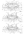
- Fig. 1 shows, in cross-sectional side view, an apparatus 1 to be used with the method according to the invention, provided with a mold 2 with a mold cavity 3 therein.
- the mold comprises a first, moveable part 4 and a second, complementary part 5, fixedly arranged.
- the moveable part 4 is guided by suitable guides, which are not shown but can, for instance, be sliding pins, rails, guide rods or a press or the like and which are directly clear to the skilled person.
- the moveable part is moveable with the aid of devices suitable to that end, represented in Figs. 1-3 as piston-cylinder assemblies 7. It is clear that this may be any suitable device, for instance also a simple press, screw means such as spindles as shown in Fig. 4 , link systems or the like. These can be of relatively light design as they are only meant for moving the part 5, virtually not for absorbing tensile or pressure forces in the further cycle.
- a slide 8 is provided, moveable in the direction S between a retracted position shown in Figs. 1 and 2 , and an extended position shown in Fig. 3 .
- two wedges 9 are provided, to be called wedge-shaped elements, which are moveable in a direction P with the aid of piston-cylinder assemblies 10 which are, for instance, hydraulically driven from a central control unit 11.
- the wedges 9 move in the direction P approximately at right angles to the direction S.
- the slide 8 is provided with two surfaces 12 inclining in opposite directions, complementary to the top surfaces of the wedges 9, such that if the wedges 9 are moved inwards, towards each other, the slide 8 is moved upwards (directions viewed in the plane of the drawing) towards the extended position and vice versa.
- An inflow opening 14 terminates in the mold cavity 3 and is connected to an injection device 15, for instance a plasticizing device and, optionally, a pressing device.
- an injection device 15 for instance a plasticizing device and, optionally, a pressing device.
- flanges 16 are provided which, with the aid of blocking means 17, can be pressed and held onto each other, for keeping the mold closed.
- the blocking means comprise brackets 18 which are moveable with the aid of piston-cylinder assemblies 19 and can be pushed over the flanges 16. In this way, simply, the desired closing pressure can be obtained and maintained.
- two ribs 21 are provided extending over the entire width of the slide 8, at right angles to the plane of drawing.
- the distance D between the end 22 of the ribs leading in the direction of movement, and the oppositely located surface 23 of the mold cavity is set with the slide 8 retracted, depending on the desired product wall thickness and the plastic to be used, while the distance is set to be larger according as the melt of the plastic is higher and/or the melting temperature of the plastic is lower.
- a product can be formed, for instance a sheet with two hinges from thermoplast such as polypropylene or polyethylene, as follows.
- the mold 2 is closed from the position shown in Fig. 1 , as shown in Fig. 2 .
- the distance D is then set at a suitable value, such that the space in the mold cavity 3 is relatively great.
- plastic is introduced into the mold cavity, for instance at a pressure of between 1 and 10 bars excess pressure.
- the filling pressure is selected such that a desired, short feed time is achieved without the material properties of the plastic being adversely affected and without undesirably high pressure occurring in the mold cavity.
- the slide 8 is moved forward, in the direction of the extended position, as shown in Fig. 3 , by moving the wedges 9.
- the speed is selected dependent on the desired adiabatic heat development which should be such that the temperature of the plastic is at least substantially brought back to approximately the melting temperature thereof.
- Plastic that is, possibly, slightly solidified becomes liquid again and can be forced further into the mold so that a complete filling of the mold cavity is obtained while the product can have wall thicknesses which are, in fact, too small for the melt flow index of the respective plastic/product combination.
- some hold pressure can still be given with the aid of the injection device 15, so that undesired stresses can be pressed from the product.
- the mold can be opened again and the product can be taken out.
- the rate of movement of the or each slide is high such that the time of movement of the slide between the retracted and the extended position is relatively short with regard to the cycle time for the manufacture of a product, for instance between 0 and 10% of that time, also depending on the desired adiabatic healing.
- This can be determined by way of an experiment for each plastic-product combination or be calculated with the aid of standard tables regarding plastics, the product properties such as dimensions and flow paths, the friction which will occur when moving the slide and the heat capacity and melt temperature of the plastic.
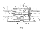
- FIG. 4 an alternative embodiment of an apparatus according to the invention is shown, wherein screw spindles 25 with nut blocks 26 are used for opening and closing the mold 2. These can be wholly or partly included in the mold 2.
- the plastic is introduced via a side inflow opening 14 and a slide 8 is provided on both sides of the mold cavity 3.
- they can be moved independently of each other but it is preferred that they be moved in coupled relation, so that a symmetrical load occurs in the mold 2.
- Table 1 Machine data Machine Stork SX 3000-2150 Machine number X 2936 Year of construction 2000 Main feed 400 V 50 Hz Main current 354 A Control voltage 24 V Max Oil pressure 210 bar Max Air pressure 8 bar Weight closing force 8700 kg Weight Injection force 5000 kg Screw diameter 65 mm
- Table 2 Mold data Length 1050 mm Width 455 mm Height 495mm Number of cavities 1
- Table 3 Produce size Length 655 mm Width 320 mm Thickness 1.7 mm
- an amount of plastic was introduced into the mold cavity, sufficient for manufacturing an end product, in this case a file.
- a shot weight of 128 grams of PP was introduced into the mold cavity.
- the mold cavity comprised a slide with a frontal surface of approximately 200,000 mm 2 , which was moved over a distance of 1.8 mm.
- the plastic was introduced, at a temperature of approximately 245°C at a speed of 750 mm/s, without pressure, at a mold temperature of approximately 50°C, and was cooled down in a first phase to approximately 230 °C.
- the slide was set in motion, which slide was moved completely forwards in approximately 0.4 sec, while the temperature in the mold rose to just below the temperature at which the plastic will decompose.
- the plastic was allowed to cool down to a temperature well below the melting temperature, close to room temperature, for instance 45 to 55°C. This cooling down was done in approximately 12 seconds.
- the product thickness on the covers and the back was on average 1.7 mm by, viewed in frontal surface, 655 mm by 320 mm. During cooling down, the application of hold pressure was not necessary, as a result of the fact that no shrinkage needed to be absorbed. The product appears to be free of stress, so that a high form-stability is obtained.
- the mold was moved with wedges with a wedge angle of approximately 4°.
- the slide is already moved to the extended position while the plastic is being injected into the mold cavity. This also contributes to the plastic being kept in motion.
- Fig. 5 a photographic depiction is given of a CD-box manufactured with a method according to the invention. Here, the flow pattern of the plastic is clearly visible. The photograph is to be explained as follows.
- a mold 2 to be used with the method according to the invention can comprise several mold cavities, while the or each mold cavity can be provided with one or more slides.
- the slides can be driven in different manners, for instance directly instead of by the wedges, and with the aid of different means, for instance electrically.
- the slides can move in different directions, for instance approximately at right angles to the direction of movement of the mold parts, or be pivoted for reducing the space in the mold cavity.
Abstract
Description
- The invention relates to a method for manufacturing products from an at least thermoplastically deformable material. Such a method is known, for instance, as injection molding.
- With known injection molding techniques, as a rule, the material to be formed such as plastic is heated in a plasticizing device to a temperature such that the material becomes virtually liquid, at least plastic and low-viscous, whereupon the material is introduced under high pressure into a mold cavity of an injection molding mold. In this mold cavity, the material is distributed such that the mold cavity is completely filled, whereupon the material is allowed to cure by cooling down. Thereupon, the product is taken out by opening the mold and ejecting the product.
- For such known injection molding techniques, a. particularly high feed pressure is to be used, especially when thin-walled products are formed, in particular if the flow paths in the mold cavity closely approach the melt flow index (MFI) of the materials to be used. Therefore, the same holds in particular when the flow paths in the mold cavity are relatively long. It is clear that with plastics with a high viscosity and/or a low melt flow, these problems occur to a larger extent. As a result, limitations are imposed on the minimum and maximum sizes of products, in particular on lengths of flow paths, on passage widths of such flow paths, on the duration of the injection molding cycles, on the materials to be used and on the minimum wall thicknesses of products, in particular of large, flat parts.
- The use of compression molding is already known. Here, into a mold cavity of a partly open mold, an amount of plastic is introduced, required for forming a desired product in this mold cavity. After the plastic has been introduced into the mold cavity, the mold is closed further, so that the plastic is pushed away for filling the further mold cavity. Therefore, with such an apparatus, at the start of the introduction of the plastic, the mold parts are to be held partly away from each other, and only afterwards to be brought onto each other relatively slowly but with high pressure. The danger exists that then, the plastic is not uniformly distributed, so that, for instance, a part of the material can be pressed sideways from the mold cavity before the mold cavity is completely closed. Also, the danger exists that insufficient or, conversely, too much plastic is introduced into the mold cavity. In this latter case, skin formation will occur between the mold halves and, moreover, it will not be possible to close the mold completely. This leads to irregularly formed products and, moreover, to pollution of the mold. A further disadvantage of this apparatus is that when materials are used with a low viscosity and/or with shallow mold halves, the material flows from the mold cavity before the mold halves are moved together, so that the earlier mentioned problems occur to an even larger extent.
-
US 4522778 discloses a method and apparatus for the production of parts made from plastic material using an injection press in which the mold cavity is defined by a mold surface and the surface of a moveable piston. Firstly, the material is introduced into the mold cavity and during injection the piston is kept stationary for a time to form a rough mold and then retracted to form a parison. Secondly, after injection has been completed the piston is advanced again, and maintained in position while cooling takes place. Thirdly, the mold is opened and the part rejected. -
EP 0999029 discloses a molding machine for molding microparts, which includes a plasticizing portion operatively connected to an injection portion and a mold portion. A linear member is associated with the injection portion to permit molding times of 0. 01 seconds at pressures up to about 690 MPa during injection of the molten plastics material into the mold portion. The shape of the mold cavity complies with the micro part to be manufactured. - An apparatus for use with the method of the type described in the opening paragraph is disclosed, wherein in a simple manner and with relatively low closing pressures, products can be manufactured having at least parts with a relatively limited wall thickness.
- Further an apparatus is disclosed, wherein different materials can be processed, in particular plastics, in particular also plastics with a high melt, i.e. plastics with a low viscosity in plastic state.
- An object of the invention is to provide a method with which, in a relatively rapid and simple manner, products can be manufactured, with relatively simple means, which products, moreover, can have relatively large, thin-walled surfaces, in particular products with wall thicknesses which are relatively small and flow path which are relatively long, smaller or longer, respectively, than matching the melt flow index associated with the material from which the product is manufactured.
- The disclosure further contemplates providing an improved use of an injection mold with a slide.
- A number of these and many other objects are achieved with a method according to the invention.
- The invention relates to a method for forming products, characterized by the features of
claim 1. - With such a method, in a rapid and simple manner, plastic products can be manufactured, while low pressures can be used for injection of the plastic as well as closure of the mold. As low injection pressures can be used, the advantage can be achieved that no undesired chemical or mechanical changes occur in the plastic, in particular separation in the different monomers or polymers, while the closing pressure can be kept low, which is advantageous from a point of view of costs. The fact is that for that purpose, sampler apparatuses are suitable, while moreover, the mechanical load is lower and less wear will occur. A further advantage thereof is that, in principle, less space is required for such an apparatus.
- With a method according to the invention, plastic is introduced into the mold cavity while the or each slide is retracted therefrom at least partly or is pushed back upon injection, so that additional flow space is obtained. This has already been discussed hereinabove with reference to an apparatus according to the invention. Thus, the resistance the plastic experiences is reduced, so that the injection pressure can be kept low, for instance largely below the standard injection pressure for conventional injection molding of a similar type of product from the same plastic. Such standard pressures can be read from standard tables and, as a rule, are dependent on the plastic and the manner of injection, the projected surface of the products to be formed jointly and the wall thicknesses. As a result thereof, the closing pressure can also be kept low in relation to conventional injection molding, readable from the same or comparable tables on the basis of substantially the same quantities. This is directly clear to the skilled person.
- With a method according to the invention, after the mold cavity has been at least substantially filled, the or each slide is moved rapidly into the mold cavity, such that the eventual product shape is obtained. The speed of the or each slide is then set such that adiabatic heat development occurs in the plastic, so that the temperature is increased again to approximately the melting temperature of the plastic. As a result, partially solidified material will become liquid again and be pushed further into the mold cavity, while, furthermore, the remaining flow paths are relatively short so that relatively thin product parts can be formed.
- With a method according to the invention, the rate of movement of the or each slide is preferably high, such that the complete movement of the slides is carried out in a fraction of the cycle time of a product cycle, for instance in less than 10%, more in particular in less than 3% of the cycle time, preferably less than some tenths or hundredths of seconds, more in particular microseconds. As stated., this rate is set such that the desired temperature increase occurs, while the plastic properties are prevented from being adversely thermally influenced.
- With a method according to the invention, the distance between the end of the or each slide, leading in the direction of movement and facing the mold cavity in the retracted position, at least partly moved from the mold cavity, and an oppositely located wall part of the mold cavity or slide is set depending on at least the melt of the plastic, i.e. the viscosity of the plastic upon injection. Surprisingly, it has appeared that, preferably, at a higher melt, i.e. a higher viscosity, the distance is to be slightly greater than with a lower melt. Without wishing to be bound to any theory, this appears to be the result of the fact that the plastic with the higher melt will solidify sooner and the plastic with the lower melt has a more disadvantageous MFI. For any plastic/mold combination, the optimal distance can be determined in a simple manner by way of experiments.
- With an apparatus to be used with the method according to the invention, a thermoplastic material such as a plastic, in particular a thermoplastic plastic, can be introduced into a mold cavity while the mold as such is closed and the or each slide is in, or is being brought into, a retracted position at introduction of the material, so that the volume of the mold cavity is relatively large with respect to the volume of the product to be eventually formed. After the material has been introduced entirely or, preferably, substantially into the mold cavity, the or each slide can be moved forcefully and, in particular, with speed into the mold cavity, at least into the material introduced therein, so that this is pushed away. With it, a speed is developed such that, as a result of the movement of the or each slide, heat development occurs in the material. To that end, the movement means are designed such that the slide can move at the desired high speed and with the desired accuracy.
- The movement means and the slide are designed such that adiabatic heat development occurs, so that the temperature in the material rises preferably above the melting temperature of the respective material.
- In an advantageous embodiment, the closing means are included at least partly in or on the mold, preferably such that no press is required or that a press without guide rod can suffice. Optionally, also, blocking means can be provided on the mold for holding the mold in closed condition during introduction of the material and displacement of the or each slide.
- With the apparatus, the mold can be held closed with relatively little closing pressure and the plastic can be introduced, in comparison with a conventional injection molding apparatus. By way of illustration: with conventional injection molding, feed pressures of between, for instance, 350 bars and 1000 bars or more are used, with closing pressures of, for instance, 0.25 to 1.25 ton/cm2, depending on, in particular, the material used, the wall thickness and the maximum flow path. With a method according to the invention, for comparable products, a feed pressure of, for instance, between 0 and 200 bars excess pressure can suffice, while relatively low pressures are preferred, for instance of some tens of bars or less. In the Table, an operating pressure of approximately 300 bar (operating pressure of the cylinders of the slides) is given, while the closing pressure can be, for instance, less than 0.2 ton/cm2. With polypropylene, for instance, a closing pressure of 0.025 to 0.1 ton/cm2 instead of between 0.25 to 1.25 ton/cm2 can suffice.
- Without wishing to be bound to any theory, this appears, in particular, to be the result of the insight that by temporarily increasing the volume of the mold cavity, at least when introducing the larger part of the material such as the plastic into the mold cavity, the relation between the length of the flow paths and their passage, substantially determined by the minimum wall thickness of the product to be formed, becomes more favorable, so that the material experiences relatively little counter pressure in the mold cavity, while the injection opening or openings are so small that upon movement of the slide or slides, the material is not pushed back through this opening or these openings. Moreover, then, the advantage appears to be achieved that due to the high speed of the or each slide, as a result of friction, so much heat is introduced into the material that solidification of the material, in particular against the mold parts and in the flow front thereof, is undone so that the viscosity of the material is reduced again, while the remaining length of the flow paths for this flow front at the start of the movement of the or each slide has been considerably reduced relative to the original length thereof. As a result, the material can be distributed in the entire mold cavity with less pressure. As the mold is then closed, in a simple manner, the material is prevented from flowing away prematurely.
- Surprisingly, it has appeared that then, a high feed rate is particularly advantageous. For instance, a feed rate can be used of between 100 and 2000 mm/s, more in particular of between 500 and 1000 mm/s. This rate is selected depending on the solidification rate of the plastic used, while it holds that the more quickly the plastic solidifies, the higher the feed rate is chosen to be. Moreover, the rate is selected depending on the mold geometry and, in particular, the de-aeration, such that undesired pressure increase in the mold cavity by compression of air is prevented.
- With the mold to be used with the method according to the invention, in the movement means, preferably, wedge-shaped elements are used which, viewed from the mold cavity, are moved behind the or a slide, such that the respective slide is moved as a result of the wedge-shape. In particular, then, for each slide at least two wedge-shaped elements are used which are pushed in opposite directions behind the slide so that a symmetrical load is obtained. Through the use of such wedge-shaped elements a favorable distribution of forces is obtained and the slides can be moved over the desired distance with relatively little force.
- In the mold, preferably, at least one slide is provided at the location where the smallest wall thickness is provided in a. product and/or at the location where the flow paths have the greatest length and/or at the location where the flow paths have the greatest complexity. By retracting the slides in those parts upon injection of the plastic, at least moving them partly from the mold cavity, additional space is created for allowing the plastic to pass exactly at the location where the plastic experiences the most resistance or at the location where excessive pressures would be necessary for allowing the plastic to pass. This holds in particular at the location where already some solidification of the plastic occurs. The adiabatic heat introduced later causes the plastic to flow further, while, moreover, the displacement of the slide effects the further movement of the plastic. Furthermore, with such a mold, relatively large, thin-walled product parts can be obtained with wall thicknesses that cannot be obtained with conventional injection molding technique.
- Slides in the mold can have a frontal surface which is relatively large in relation to the projected surface of the product. Herein, projected surface is understood to include the surface of the product projected on a plane at right angles to the closing direction of the mold. For instance, the frontal surface of the slide can be more than 20% of this projected surface. Surfaces of more than 50%, for instance of 75%, 85% or 95% or more are possible. With this, the advantage is achieved that in a major part of the mold cavity, the space for primary flow of the material to be formed is increased, while, eventually, thin-walled products can be manufactured. As a result of this as well, the feed pressure and the closing pressure can be kept even lower.
- In the subclaims, further advantageous embodiments of the invention are described. In clarification of the invention, exemplary embodiments of an apparatus, method, use and product will be described with reference to the drawing. In the drawing:
-
Fig. 1 shows, in partly cross-sectional side view, an apparatus to be used with the method according to the invention, with partly opened mold; -
Fig. 2 shows, in partly cross-sectional side view, an apparatus to be used with the method according to the invention, with a closed mold and retracted slide; -
Fig. 3 shows, in partly cross-sectional side view, an apparatus to be used with the method according to the invention, with a closed mold and forwardly moved slide; -
Fig. 4 shows, in partly cross-sectional side view, an alternative embodiment of an apparatus to be used with the method according to the invention; and - Fig. 5 shows a depiction of a CD-box manufactured according to the invention, photographically recorded using colorant.
- In this description, identical or corresponding parts have identical or corresponding reference numerals. The embodiments shown are only given by way of example and should not be taken as being limitative in any way.
-
Fig. 1 shows, in cross-sectional side view, anapparatus 1 to be used with the method according to the invention, provided with amold 2 with amold cavity 3 therein. The mold comprises a first,moveable part 4 and a second,complementary part 5, fixedly arranged. Themoveable part 4 is guided by suitable guides, which are not shown but can, for instance, be sliding pins, rails, guide rods or a press or the like and which are directly clear to the skilled person. The moveable part is moveable with the aid of devices suitable to that end, represented inFigs. 1-3 as piston-cylinder assemblies 7. It is clear that this may be any suitable device, for instance also a simple press, screw means such as spindles as shown inFig. 4 , link systems or the like. These can be of relatively light design as they are only meant for moving thepart 5, virtually not for absorbing tensile or pressure forces in the further cycle. - In the
fixed part 5, aslide 8 is provided, moveable in the direction S between a retracted position shown inFigs. 1 and 2 , and an extended position shown inFig. 3 . For moving theslide 8, twowedges 9 are provided, to be called wedge-shaped elements, which are moveable in a direction P with the aid of piston-cylinder assemblies 10 which are, for instance, hydraulically driven from acentral control unit 11. Thewedges 9 move in the direction P approximately at right angles to the direction S. At the underside, theslide 8 is provided with twosurfaces 12 inclining in opposite directions, complementary to the top surfaces of thewedges 9, such that if thewedges 9 are moved inwards, towards each other, theslide 8 is moved upwards (directions viewed in the plane of the drawing) towards the extended position and vice versa. - An
inflow opening 14 terminates in themold cavity 3 and is connected to aninjection device 15, for instance a plasticizing device and, optionally, a pressing device. On bothparts mold 2,flanges 16 are provided which, with the aid of blocking means 17, can be pressed and held onto each other, for keeping the mold closed. To that end, in the embodiment shown, the blocking meanscomprise brackets 18 which are moveable with the aid of piston-cylinder assemblies 19 and can be pushed over theflanges 16. In this way, simply, the desired closing pressure can be obtained and maintained. - As an example, on the
top surface 20 of theslide 8, tworibs 21 are provided extending over the entire width of theslide 8, at right angles to the plane of drawing. The distance D between theend 22 of the ribs leading in the direction of movement, and the oppositely locatedsurface 23 of the mold cavity is set with theslide 8 retracted, depending on the desired product wall thickness and the plastic to be used, while the distance is set to be larger according as the melt of the plastic is higher and/or the melting temperature of the plastic is lower. - With an apparatus according to
Figs. 1- 3 , a product can be formed, for instance a sheet with two hinges from thermoplast such as polypropylene or polyethylene, as follows. - The
mold 2 is closed from the position shown inFig. 1 , as shown inFig. 2 . The distance D is then set at a suitable value, such that the space in themold cavity 3 is relatively great. Through theinflow opening 14, under relatively low pressure, plastic is introduced into the mold cavity, for instance at a pressure of between 1 and 10 bars excess pressure. The filling pressure is selected such that a desired, short feed time is achieved without the material properties of the plastic being adversely affected and without undesirably high pressure occurring in the mold cavity. Then, at a relatively high speed, theslide 8 is moved forward, in the direction of the extended position, as shown inFig. 3 , by moving thewedges 9. Here, the speed is selected dependent on the desired adiabatic heat development which should be such that the temperature of the plastic is at least substantially brought back to approximately the melting temperature thereof. Plastic that is, possibly, slightly solidified becomes liquid again and can be forced further into the mold so that a complete filling of the mold cavity is obtained while the product can have wall thicknesses which are, in fact, too small for the melt flow index of the respective plastic/product combination. Optionally, after moving the slide, some hold pressure can still be given with the aid of theinjection device 15, so that undesired stresses can be pressed from the product. - After that, the mold can be opened again and the product can be taken out.
- Preferably, the rate of movement of the or each slide is high such that the time of movement of the slide between the retracted and the extended position is relatively short with regard to the cycle time for the manufacture of a product, for instance between 0 and 10% of that time, also depending on the desired adiabatic healing. This can be determined by way of an experiment for each plastic-product combination or be calculated with the aid of standard tables regarding plastics, the product properties such as dimensions and flow paths, the friction which will occur when moving the slide and the heat capacity and melt temperature of the plastic.
- In
Fig. 4 , an alternative embodiment of an apparatus according to the invention is shown, whereinscrew spindles 25 with nut blocks 26 are used for opening and closing themold 2. These can be wholly or partly included in themold 2. In this embodiment, the plastic is introduced via aside inflow opening 14 and aslide 8 is provided on both sides of themold cavity 3. In this embodiments, they can be moved independently of each other but it is preferred that they be moved in coupled relation, so that a symmetrical load occurs in themold 2. - By way of illustration, an embodiment of the method according to the invention will be described. As a product example, a plastic file is taken. In Table 1, the data of the injection molding machine are included, in Table 2 the mold data, in Table 3 the product dimensions, in Table 4 the data about the slides or pressure plate and in Table 5 data involving the operation parameters. In Table 6, the pressures and speeds used during a injection moulding cycle are given. Thereupon, in the graph, the temperature in the plastic in a mold according to the invention during an injection molding cycle is given, plotted against time.
Table 1: Machine data Machine Stork SX 3000-2150 Machine number X 2936 Year of construction 2000 Main feed 400 V 50 Hz Main current 354 A Control voltage 24 V Max Oil pressure 210 bar Max Air pressure 8 bar Weight closing force 8700 kg Weight Injection force 5000 kg Screw diameter 65 mm Table 2: Mold data Length 1050 mm Width 455 mm Height 495mm Number of cavities 1 Table 3: Produce size Length 655 mm Width 320 mm Thickness 1.7 mm Table 4: Pressure plate data Cylinder stroke 50 mm Cylinder diameter 80 mm Operating pressure 300 bar Wedge angle 4 ° Table 5: Parameters Mold temperature 50 ° Temperature at introduction 245° Dosing 128 mm Shot weight 295 gram Impact of the pressure plate 80 mm Decompression 10 mm Closing force 150 ton Hold pressure 25 bar Thrust 20 bar Speed of impact 0.4 S Table 6: Cycle time Sub time At time Total time Closing 0.750 S T = 0.000 S 0.750 S Injection 0,171 S 0,750 S 0,921 S Impact pressure plate 0.400 S 0.857 S 1.257 S Cooling 12.000 S 1.257 S 13.257 S Opening 1.000 S 13.257 S 14.257 S Handling 5.000 S 14.257 S 19.257 S 
- With a method according to the invention, at a time 0, with the mold closed, an amount of plastic was introduced into the mold cavity, sufficient for manufacturing an end product, in this case a file. In 0.1706 sec, a shot weight of 128 grams of PP was introduced into the mold cavity. The mold cavity comprised a slide with a frontal surface of approximately 200,000 mm2, which was moved over a distance of 1.8 mm. The plastic was introduced, at a temperature of approximately 245°C at a speed of 750 mm/s, without pressure, at a mold temperature of approximately 50°C, and was cooled down in a first phase to approximately 230 °C. At the time T1, after approximately 0.107 seconds, the slide was set in motion, which slide was moved completely forwards in approximately 0.4 sec, while the temperature in the mold rose to just below the temperature at which the plastic will decompose. From the time T2, at which the slide was completely moved forward and was held in that position, the plastic was allowed to cool down to a temperature well below the melting temperature, close to room temperature, for instance 45 to 55°C. This cooling down was done in approximately 12 seconds. Apart from two living hinges, the product thickness on the covers and the back was on average 1.7 mm by, viewed in frontal surface, 655 mm by 320 mm. During cooling down, the application of hold pressure was not necessary, as a result of the fact that no shrinkage needed to be absorbed. The product appears to be free of stress, so that a high form-stability is obtained.
- As a result of the high speed of the slide, kinetic speed is converted to heat, while, moreover, friction between the plastic and the mold as well as in the plastic itself and the compression leads to adiabatic heat development. Until approximately the moment T2 the slide is completely moved forward, the plastic in the mold is kept in motion and, furthermore, kept above the melting temperature, so that solidification is prevented and the flow behavior of the plastic is positively influenced. As a result, a complete filling of the mold cavity is obtained with limited closing force and filling pressure.
- The mold was moved with wedges with a wedge angle of approximately 4°.
- With a method according to the invention as described herein, the slide is already moved to the extended position while the plastic is being injected into the mold cavity. This also contributes to the plastic being kept in motion.
- In Fig. 5, a photographic depiction is given of a CD-box manufactured with a method according to the invention. Here, the flow pattern of the plastic is clearly visible. The photograph is to be explained as follows.
- With conventional injections, a tangle of lines would be visible. With conventional injecting, these lines are caused by plastic being supplied under pressure. A very dark, confused pattern becomes visible and indicates the presence of stresses in the material. Conversely, in this picture, a particularly quiet image presents itself with attractive, long threaded light patterns. A slight hold pressure causes the two dark spots around the points of injection. In itself, this hold pressure is not necessary but hold pressure can be advantageous for further improving the product, in particular the flatness thereof. The slightly darker spots near the center are the result of this hold pressure which, clearly, has remained particularly limited.

- The invention is not limited in any manner to the embodiments represented in the drawing and the description. Many variations thereon are possible within the framework of the invention as outlined by the claims. For instance, a
mold 2 to be used with the method according to the invention can comprise several mold cavities, while the or each mold cavity can be provided with one or more slides. The slides can be driven in different manners, for instance directly instead of by the wedges, and with the aid of different means, for instance electrically. Also, the slides can move in different directions, for instance approximately at right angles to the direction of movement of the mold parts, or be pivoted for reducing the space in the mold cavity. - These and many comparable adaptations are possible within the framework of the invention as outlined by the claims.
Claims (7)
- A method for forming plastic products, wherein in a mold cavity (3) an amount of plastic is introduced with a feed pressure of less than 350 bar, preferably between 0 and 200 bar in substantially plastic condition, whereupon at least one moveable element to be called a slide (8) is moved at least partly into the respective mold cavity (3) while compressing and/or displacing at least a part of the plastic, wherein the speed of movement of the at least one slide (8) is so high that adiabatic heat development occurs in the plastic, such that the plastic becomes more liquid, at least its viscosity is decreased and the temperature of the plastic is at least substantially brought back to approximately the melting temperature thereof.
- A method according to claim 1, wherein, prior to the introduction of the plastic into the mold cavity, the at least one slide is set at a passage distance, determined by the distance between one end, leading in the direction of movement, of the respective slide (8) and an oppositely located wall part of the mold cavity, which distance is set on the basis of the melt of the plastic to be used in the mold cavity.
- A method according to any one of claims 1- 2, wherein the or each slide (8) is moved at a speed such that the movement of the respective slide takes place in, at most, approximately 20% of the total cycle time of a manufacturing cycle, determined by the time between the closure of the mold and the extraction of a ready product.
- A method according to claim 3, wherein said movement of the or each slide (8) is carried out in less than 10%, in particular in less than 5% and preferably in less than 3% of the total cycle time.
- A method according to any one of claims 1 - 4, wherein as material a plastic is introduced, in particular a thermoplastic plastic, while the feed pressure and speed are such that at least partial solidification of the plastic occurs during introduction of the plastic, while the or each slide (8) is brought into the mold cavity (3) such that therein adiabatic heat development takes place such that the plastic returns to a liquid condition, at least that its viscosity is reduced such that by moving the slide and, optionally, applying hold pressure, the respective mold cavity is completely filled.
- A method according to claim 5, wherein in the or each mold cavity (3) overflow spaces are provided which are filled with the plastic, wherein the parts filled in the overflow spaces are used as engaging elements for extracting a product formed in the respective mold cavity.
- A method according to any one of claims 1 - 6, wherein a mold cavity is used comprising at least one forming part for forming a thin-walled product part, while at least one slide (8) is provided in or adjacent said forming part and which has a direction of movement including an angle with a plane parallel to said small wall thickness of said product part, in particular an angle between 30 and 90°, while, with the slide (8) in a first, retracted position said product forming part defines a relatively large passage and in a second, extended position, defines a passage which corresponds to the cross section of the thin-walled product part to be formed, wherein the passage with the slide in the second position is made at least partly smaller than matching the melt-flow index (MFI) of the plastic to be introduced during use while, with the slide (8) in the first position, the passage is considerably greater than matching said MFI.
Priority Applications (1)
| Application Number | Priority Date | Filing Date | Title |
|---|---|---|---|
| EP08172917A EP2033761A1 (en) | 2002-09-10 | 2003-09-10 | Apparatus and method for manufacturing products from a thermoplastic mass |
Applications Claiming Priority (3)
| Application Number | Priority Date | Filing Date | Title |
|---|---|---|---|
| NL1021421 | 2002-09-10 | ||
| NL1021421A NL1021421C2 (en) | 2002-09-10 | 2002-09-10 | Device and method for manufacturing products from a warm plastic mass. |
| PCT/NL2003/000630 WO2004024416A1 (en) | 2002-09-10 | 2003-09-10 | Apparatus and method for manufacturing products from a thermoplastic mass |
Related Child Applications (1)
| Application Number | Title | Priority Date | Filing Date |
|---|---|---|---|
| EP08172917A Division EP2033761A1 (en) | 2002-09-10 | 2003-09-10 | Apparatus and method for manufacturing products from a thermoplastic mass |
Publications (2)
| Publication Number | Publication Date |
|---|---|
| EP1560694A1 EP1560694A1 (en) | 2005-08-10 |
| EP1560694B1 true EP1560694B1 (en) | 2009-02-25 |
Family
ID=31987577
Family Applications (2)
| Application Number | Title | Priority Date | Filing Date |
|---|---|---|---|
| EP03795499A Expired - Lifetime EP1560694B1 (en) | 2002-09-10 | 2003-09-10 | Method for manufacturing products from a thermoplastic mass |
| EP08172917A Withdrawn EP2033761A1 (en) | 2002-09-10 | 2003-09-10 | Apparatus and method for manufacturing products from a thermoplastic mass |
Family Applications After (1)
| Application Number | Title | Priority Date | Filing Date |
|---|---|---|---|
| EP08172917A Withdrawn EP2033761A1 (en) | 2002-09-10 | 2003-09-10 | Apparatus and method for manufacturing products from a thermoplastic mass |
Country Status (13)
| Country | Link |
|---|---|
| US (3) | US7504059B2 (en) |
| EP (2) | EP1560694B1 (en) |
| JP (1) | JP2005537958A (en) |
| CN (2) | CN1705552B (en) |
| AT (1) | ATE423668T1 (en) |
| AU (1) | AU2003263668A1 (en) |
| CA (1) | CA2512578C (en) |
| DE (1) | DE60326372D1 (en) |
| DK (1) | DK1560694T3 (en) |
| ES (1) | ES2323171T3 (en) |
| NL (2) | NL1021421C2 (en) |
| PT (1) | PT1560694E (en) |
| WO (1) | WO2004024416A1 (en) |
Families Citing this family (24)
| Publication number | Priority date | Publication date | Assignee | Title |
|---|---|---|---|---|
| JP4659300B2 (en) * | 2000-09-13 | 2011-03-30 | 浜松ホトニクス株式会社 | Laser processing method and semiconductor chip manufacturing method |
| NL1023365C2 (en) * | 2003-05-08 | 2004-11-09 | Fountain Patents B V | Method and device for manufacturing vehicle parts. |
| US7293981B2 (en) * | 2004-04-23 | 2007-11-13 | Husky Injection Molding Systems Ltd. | Apparatus for injection molding using active material elements |
| NL1027261C2 (en) * | 2004-10-15 | 2006-04-24 | Ecim Technologies Bv | Device and method for manufacturing plastic products. |
| NL1027638C2 (en) * | 2004-12-01 | 2006-06-02 | Ecim Technologies Bv | Information carrier and method and device for its manufacture. |
| ATE468961T1 (en) | 2004-12-07 | 2010-06-15 | 3M Innovative Properties Co | METHOD FOR SHAPING A MICRONEEDLE |
| US7687003B2 (en) | 2004-12-08 | 2010-03-30 | Visteon Global Technologies, Inc. | Method of forming plastic part having hidden thin walled section |
| NL1027910C2 (en) * | 2004-12-28 | 2006-06-29 | Ecim Technologies Bv | Method and device for the manufacture of products. |
| JP4923924B2 (en) | 2005-11-22 | 2012-04-25 | コニカミノルタホールディングス株式会社 | Imprint apparatus and imprint method |
| NL1032248C2 (en) | 2006-07-28 | 2008-01-29 | Ecim Technologies Bv | Method and device for manufacturing products. |
| NL1032947C2 (en) * | 2006-11-27 | 2008-05-28 | Ecim Technologies Bv | Device and method for forming products. |
| EP2145746A1 (en) | 2008-07-16 | 2010-01-20 | I-Pac Patents B.V. | Method of manufacturing a plastic package in a mold |
| US8574472B2 (en) | 2008-09-15 | 2013-11-05 | Momexx B.V. | Moulding device |
| CN101774256B (en) * | 2009-12-29 | 2012-10-17 | 广州毅昌科技股份有限公司 | Compression injection molding machine and use method thereof |
| US8974224B2 (en) * | 2011-03-08 | 2015-03-10 | Craig M. Stanley | Position-locking apparatus for insert and over molding of delicate components |
| JP2012250510A (en) * | 2011-06-06 | 2012-12-20 | Seiko Epson Corp | Injection mold, injection-molded article, and injection molding method |
| CN104918765B (en) * | 2013-02-01 | 2017-05-17 | 赫斯基注塑系统有限公司 | Molding system having an adjustable mold shut height |
| NL2011765C2 (en) | 2013-11-08 | 2015-05-19 | Vitaplus Nederland B V | DEVICE AND METHOD FOR LIMITING THE QUANTITY OF FLUID. |
| FR3029446B1 (en) * | 2014-12-05 | 2017-01-13 | Plastic Omnium Cie | MOLD FOR MANUFACTURING A PLASTIC PART COMPRISING A SYSTEM FOR REALIZING ORIFICES IN THE WORKPIECE |
| GB2544717B (en) * | 2015-09-25 | 2019-04-10 | Gr8 Eng Ltd | Injection Molding Method |
| CN106273206B (en) * | 2016-08-18 | 2019-01-01 | 天津华夏联盛汽车部件有限公司 | A kind of front bumper face shield injection molding technique |
| DE102016119636B3 (en) * | 2016-10-14 | 2018-02-08 | Carl Zeiss Smart Optics Gmbh | Molding tool and use of the same |
| CN109049546A (en) * | 2018-07-16 | 2018-12-21 | 温州职业技术学院 | A kind of type chamber adjustable height injection mold |
| CN111703026A (en) * | 2020-07-20 | 2020-09-25 | 漳州市吉盛精密模具有限公司 | Plastic mould for quickly forming plastic ring |
Family Cites Families (33)
| Publication number | Priority date | Publication date | Assignee | Title |
|---|---|---|---|---|
| US3208105A (en) * | 1962-04-13 | 1965-09-28 | Charles S White | Molding press |
| US3195186A (en) * | 1962-06-13 | 1965-07-20 | Inv S Finance Corp | Apparatus for clamping mold parts |
| US4184835A (en) * | 1978-09-28 | 1980-01-22 | General Electric Company | Mold apparatus |
| JPS58211424A (en) * | 1982-06-02 | 1983-12-08 | Ricoh Co Ltd | Injection-compression molding machine |
| FR2545033B1 (en) | 1983-04-28 | 1985-08-16 | Cibie Projecteurs | PROCESS AND DEVICE FOR THE PRODUCTION OF PLASTIC MATERIALS, ON AN INJECTION PRESS |
| US4778632A (en) * | 1986-01-06 | 1988-10-18 | Neolens, Inc. | Injection molding equipment and method |
| DE3718106A1 (en) * | 1987-05-27 | 1988-12-15 | Mannesmann Ag | PRECISION CLOSING UNIT FOR AN INJECTION MOLDING MACHINE |
| US4980115A (en) * | 1987-05-28 | 1990-12-25 | Yoshida Industry Co. Ltd. | Method for making an injection-molded product having a partly thin portion |
| US5049344A (en) * | 1988-06-02 | 1991-09-17 | Primtec | Method for reducing required mold-cavity clamping force and controlling injection-molded-product wall thickness |
| DE69021824T2 (en) * | 1989-10-27 | 1996-04-18 | Mitsubishi Heavy Ind Ltd | Injection molding process and apparatus therefor. |
| JPH03161317A (en) * | 1989-11-21 | 1991-07-11 | Toshiba Corp | Injection compression mold |
| TW205018B (en) * | 1990-11-30 | 1993-05-01 | Toshiba Machine Co Ltd | |
| JPH04263916A (en) * | 1991-02-20 | 1992-09-18 | Toshiba Corp | Mold assembly |
| WO1993001926A1 (en) * | 1991-07-15 | 1993-02-04 | Komatsu Ltd. | Method of injection-compression molding in injection molding machine |
| JPH0615711A (en) * | 1992-04-08 | 1994-01-25 | Dr Spiess Kunststoff Recycling Gmbh & Co | Method and device for automatically producing material from synthetic substance, esp. recycled synthetic substance |
| JPH06126791A (en) * | 1992-10-21 | 1994-05-10 | Toyo Mach & Metal Co Ltd | Method for controlling compressive force in injection molding machine |
| JPH06126790A (en) * | 1992-10-21 | 1994-05-10 | Toyo Mach & Metal Co Ltd | Method for controlling compression in injection compression molding machine |
| US5424017A (en) * | 1993-04-12 | 1995-06-13 | Hinduja; Murli L. | Method for forming fiber-reinforced articles |
| JPH06328489A (en) * | 1993-05-24 | 1994-11-29 | Japan Steel Works Ltd:The | Method and apparatus for injection press molding |
| JP3331680B2 (en) * | 1993-07-13 | 2002-10-07 | アイシン精機株式会社 | Sandwich molded article manufacturing method and molding apparatus |
| GB2282560B (en) * | 1993-09-14 | 1997-12-17 | Idemitsu Petrochemical Co | Compression equipment of injection compression molding machine and injection compression molding machine |
| JPH0885285A (en) * | 1994-07-21 | 1996-04-02 | Hitachi Maxell Ltd | Manufacture of board for security card and the same board for the card |
| US5993719A (en) * | 1994-09-08 | 1999-11-30 | Idemitsu Petrochemical Co., Ltd. | Method of producing a laminated molding |
| US5512221A (en) * | 1994-12-22 | 1996-04-30 | Galic Maus Ventures | Lens thickness adjustment method and apparatus in a thermoplastic injection mold for ophthalmic finished spectacle lenses |
| JP3300562B2 (en) * | 1995-03-14 | 2002-07-08 | 出光石油化学株式会社 | Injection compression molding method and injection compression molding apparatus |
| KR100475398B1 (en) * | 1996-02-16 | 2005-05-16 | 이데미쓰세끼유가가꾸가부시끼가이샤 | A method of forming a light-weight, fiber-reinforced thermoplastic resin product and a light-weight molded product |
| US6248281B1 (en) * | 1996-11-14 | 2001-06-19 | Idemitsu Petrochemical Co., Ltd. | Compression apparatus for molding, injection compression molding machine, and injection compression molding method using the compression device |
| JP3943696B2 (en) * | 1998-03-11 | 2007-07-11 | 株式会社プライムポリマー | Manufacturing method of laminated molded product |
| JP4146026B2 (en) * | 1998-04-24 | 2008-09-03 | 株式会社プライムポリマー | Molding apparatus and molding method |
| US6267580B1 (en) * | 1998-11-02 | 2001-07-31 | Murray Incorporated | Micro injection molding machine |
| JP2002096356A (en) * | 2000-09-22 | 2002-04-02 | Honda Motor Co Ltd | Injection compression molding mold |
| DE10113224A1 (en) * | 2001-03-19 | 2002-10-02 | Ap & T Schaefer Technologie Gm | Closing unit for tools to be compressed against rising forces |
| AUPR393001A0 (en) * | 2001-03-23 | 2001-04-26 | Sola International Holdings Ltd | Injection molding method |
-
2002
- 2002-09-10 NL NL1021421A patent/NL1021421C2/en not_active IP Right Cessation
-
2003
- 2003-09-10 EP EP03795499A patent/EP1560694B1/en not_active Expired - Lifetime
- 2003-09-10 CA CA2512578A patent/CA2512578C/en not_active Expired - Fee Related
- 2003-09-10 ES ES03795499T patent/ES2323171T3/en not_active Expired - Lifetime
- 2003-09-10 US US10/527,364 patent/US7504059B2/en not_active Expired - Fee Related
- 2003-09-10 PT PT03795499T patent/PT1560694E/en unknown
- 2003-09-10 NL NL1024263A patent/NL1024263C2/en not_active IP Right Cessation
- 2003-09-10 JP JP2004535279A patent/JP2005537958A/en active Pending
- 2003-09-10 AU AU2003263668A patent/AU2003263668A1/en not_active Abandoned
- 2003-09-10 CN CN03824756.9A patent/CN1705552B/en not_active Expired - Fee Related
- 2003-09-10 EP EP08172917A patent/EP2033761A1/en not_active Withdrawn
- 2003-09-10 DE DE60326372T patent/DE60326372D1/en not_active Expired - Lifetime
- 2003-09-10 WO PCT/NL2003/000630 patent/WO2004024416A1/en active Application Filing
- 2003-09-10 DK DK03795499T patent/DK1560694T3/en active
- 2003-09-10 AT AT03795499T patent/ATE423668T1/en active
- 2003-09-10 CN CN201010124834A patent/CN101863109A/en active Pending
-
2009
- 2009-01-21 US US12/321,425 patent/US7891970B2/en not_active Expired - Fee Related
-
2011
- 2011-02-01 US US13/018,960 patent/US8360769B2/en not_active Expired - Fee Related
Also Published As
| Publication number | Publication date |
|---|---|
| EP1560694A1 (en) | 2005-08-10 |
| US7504059B2 (en) | 2009-03-17 |
| CN1705552A (en) | 2005-12-07 |
| US8360769B2 (en) | 2013-01-29 |
| EP2033761A1 (en) | 2009-03-11 |
| US20090194909A1 (en) | 2009-08-06 |
| DK1560694T3 (en) | 2009-06-15 |
| JP2005537958A (en) | 2005-12-15 |
| ATE423668T1 (en) | 2009-03-15 |
| AU2003263668A1 (en) | 2004-04-30 |
| US20110123662A1 (en) | 2011-05-26 |
| PT1560694E (en) | 2009-06-01 |
| ES2323171T3 (en) | 2009-07-08 |
| CN1705552B (en) | 2010-05-05 |
| WO2004024416A8 (en) | 2005-06-09 |
| US7891970B2 (en) | 2011-02-22 |
| CA2512578C (en) | 2015-05-26 |
| US20060033228A1 (en) | 2006-02-16 |
| DE60326372D1 (en) | 2009-04-09 |
| NL1021421C2 (en) | 2004-03-11 |
| CA2512578A1 (en) | 2004-03-25 |
| WO2004024416A1 (en) | 2004-03-25 |
| NL1024263C2 (en) | 2004-03-16 |
| CN101863109A (en) | 2010-10-20 |
Similar Documents
| Publication | Publication Date | Title |
|---|---|---|
| EP1560694B1 (en) | Method for manufacturing products from a thermoplastic mass | |
| NL1028066C2 (en) | Method and device for the manufacture of labeled plastic products. | |
| CA2435947C (en) | Moulding | |
| US5922266A (en) | Injection molding | |
| EP0172536B1 (en) | Injection molding process for molten plastic | |
| EP1986839B1 (en) | Process for production of thin-walled plastics mouldings | |
| EP1912773B1 (en) | Method, control for a machine and computer program product for controlling a machine for producing a molded element, especially injection molding method | |
| NL1027261C2 (en) | Device and method for manufacturing plastic products. | |
| CN100509346C (en) | Resin molding machine | |
| RU2455159C2 (en) | Method of injection moulding and injection moulding machine | |
| JP3151412B2 (en) | Resin molding equipment | |
| JP3011097U (en) | Injection molding equipment | |
| JP2553868Y2 (en) | Injection mold for thin resin flat plate | |
| JP4565819B2 (en) | Injection molding method and injection mold for thick and long products | |
| JPH11105084A (en) | Injection mold apparatus and injection molding method using the same | |
| JPH06305746A (en) | Mold for forming optical glass lens | |
| JPH01118422A (en) | Injection compression molding die | |
| JPH04189520A (en) | Injection mold | |
| JPH05116193A (en) | Injection molding method | |
| JPH05337988A (en) | Injection mold |
Legal Events
| Date | Code | Title | Description |
|---|---|---|---|
| PUAI | Public reference made under article 153(3) epc to a published international application that has entered the european phase |
Free format text: ORIGINAL CODE: 0009012 |
|
| 17P | Request for examination filed |
Effective date: 20050311 |
|
| AK | Designated contracting states |
Kind code of ref document: A1 Designated state(s): AT BE BG CH CY CZ DE DK EE ES FI FR GB GR HU IE IT LI LU MC NL PT RO SE SI SK TR |
|
| AX | Request for extension of the european patent |
Extension state: AL LT LV MK |
|
| DAX | Request for extension of the european patent (deleted) | ||
| RAP1 | Party data changed (applicant data changed or rights of an application transferred) |
Owner name: ECIM TECHNOLOGIES B.V. |
|
| RAP1 | Party data changed (applicant data changed or rights of an application transferred) |
Owner name: ECIM TECHNOLOGIES B.V. |
|
| 17Q | First examination report despatched |
Effective date: 20050915 |
|
| GRAP | Despatch of communication of intention to grant a patent |
Free format text: ORIGINAL CODE: EPIDOSNIGR1 |
|
| RTI1 | Title (correction) |
Free format text: METHOD FOR MANUFACTURING PRODUCTS FROM A THERMOPLASTIC MASS |
|
| GRAS | Grant fee paid |
Free format text: ORIGINAL CODE: EPIDOSNIGR3 |
|
| GRAA | (expected) grant |
Free format text: ORIGINAL CODE: 0009210 |
|
| AK | Designated contracting states |
Kind code of ref document: B1 Designated state(s): AT BE BG CH CY CZ DE DK EE ES FI FR GB GR HU IE IT LI LU MC NL PT RO SE SI SK TR |
|
| REG | Reference to a national code |
Ref country code: GB Ref legal event code: FG4D |
|
| REG | Reference to a national code |
Ref country code: CH Ref legal event code: EP |
|
| REG | Reference to a national code |
Ref country code: IE Ref legal event code: FG4D |
|
| REF | Corresponds to: |
Ref document number: 60326372 Country of ref document: DE Date of ref document: 20090409 Kind code of ref document: P |
|
| REG | Reference to a national code |
Ref country code: RO Ref legal event code: EPE |
|
| REG | Reference to a national code |
Ref country code: PT Ref legal event code: SC4A Free format text: AVAILABILITY OF NATIONAL TRANSLATION Effective date: 20090522 |
|
| REG | Reference to a national code |
Ref country code: SE Ref legal event code: TRGR |
|
| REG | Reference to a national code |
Ref country code: DK Ref legal event code: T3 Ref country code: CH Ref legal event code: NV Representative=s name: R. A. EGLI & CO. PATENTANWAELTE |
|
| REG | Reference to a national code |
Ref country code: ES Ref legal event code: FG2A Ref document number: 2323171 Country of ref document: ES Kind code of ref document: T3 |
|
| PG25 | Lapsed in a contracting state [announced via postgrant information from national office to epo] |
Ref country code: SI Free format text: LAPSE BECAUSE OF FAILURE TO SUBMIT A TRANSLATION OF THE DESCRIPTION OR TO PAY THE FEE WITHIN THE PRESCRIBED TIME-LIMIT Effective date: 20090225 |
|
| PG25 | Lapsed in a contracting state [announced via postgrant information from national office to epo] |
Ref country code: EE Free format text: LAPSE BECAUSE OF FAILURE TO SUBMIT A TRANSLATION OF THE DESCRIPTION OR TO PAY THE FEE WITHIN THE PRESCRIBED TIME-LIMIT Effective date: 20090225 |
|
| PGFP | Annual fee paid to national office [announced via postgrant information from national office to epo] |
Ref country code: DK Payment date: 20090910 Year of fee payment: 7 Ref country code: ES Payment date: 20090924 Year of fee payment: 7 Ref country code: IE Payment date: 20090921 Year of fee payment: 7 |
|
| PG25 | Lapsed in a contracting state [announced via postgrant information from national office to epo] |
Ref country code: SK Free format text: LAPSE BECAUSE OF FAILURE TO SUBMIT A TRANSLATION OF THE DESCRIPTION OR TO PAY THE FEE WITHIN THE PRESCRIBED TIME-LIMIT Effective date: 20090225 |
|
| PGFP | Annual fee paid to national office [announced via postgrant information from national office to epo] |
Ref country code: FI Payment date: 20090915 Year of fee payment: 7 Ref country code: HU Payment date: 20090930 Year of fee payment: 7 Ref country code: RO Payment date: 20090907 Year of fee payment: 7 Ref country code: SE Payment date: 20090915 Year of fee payment: 7 Ref country code: TR Payment date: 20090909 Year of fee payment: 7 |
|
| PLBI | Opposition filed |
Free format text: ORIGINAL CODE: 0009260 |
|
| 26 | Opposition filed |
Opponent name: IPX INTERNATIONAL B.V. Effective date: 20091125 |
|
| PLAX | Notice of opposition and request to file observation + time limit sent |
Free format text: ORIGINAL CODE: EPIDOSNOBS2 |
|
| REG | Reference to a national code |
Ref country code: HU Ref legal event code: AG4A Ref document number: E006248 Country of ref document: HU |
|
| PG25 | Lapsed in a contracting state [announced via postgrant information from national office to epo] |
Ref country code: BG Free format text: LAPSE BECAUSE OF FAILURE TO SUBMIT A TRANSLATION OF THE DESCRIPTION OR TO PAY THE FEE WITHIN THE PRESCRIBED TIME-LIMIT Effective date: 20090525 |
|
| PGFP | Annual fee paid to national office [announced via postgrant information from national office to epo] |
Ref country code: BE Payment date: 20090911 Year of fee payment: 7 |
|
| NLR1 | Nl: opposition has been filed with the epo |
Opponent name: IPX INTERNATIONAL B.V. |
|
| PG25 | Lapsed in a contracting state [announced via postgrant information from national office to epo] |
Ref country code: MC Free format text: LAPSE BECAUSE OF NON-PAYMENT OF DUE FEES Effective date: 20090930 |
|
| PLAF | Information modified related to communication of a notice of opposition and request to file observations + time limit |
Free format text: ORIGINAL CODE: EPIDOSCOBS2 |
|
| PLAF | Information modified related to communication of a notice of opposition and request to file observations + time limit |
Free format text: ORIGINAL CODE: EPIDOSCOBS2 |
|
| PLBP | Opposition withdrawn |
Free format text: ORIGINAL CODE: 0009264 |
|
| PLBD | Termination of opposition procedure: decision despatched |
Free format text: ORIGINAL CODE: EPIDOSNOPC1 |
|
| PG25 | Lapsed in a contracting state [announced via postgrant information from national office to epo] |
Ref country code: GR Free format text: LAPSE BECAUSE OF FAILURE TO SUBMIT A TRANSLATION OF THE DESCRIPTION OR TO PAY THE FEE WITHIN THE PRESCRIBED TIME-LIMIT Effective date: 20090526 |
|
| PGFP | Annual fee paid to national office [announced via postgrant information from national office to epo] |
Ref country code: CZ Payment date: 20100910 Year of fee payment: 8 |
|
| PGFP | Annual fee paid to national office [announced via postgrant information from national office to epo] |
Ref country code: PT Payment date: 20100909 Year of fee payment: 8 |
|
| PLBM | Termination of opposition procedure: date of legal effect published |
Free format text: ORIGINAL CODE: 0009276 |
|
| STAA | Information on the status of an ep patent application or granted ep patent |
Free format text: STATUS: OPPOSITION PROCEDURE CLOSED |
|
| 27C | Opposition proceedings terminated |
Effective date: 20101008 |
|
| BERE | Be: lapsed |
Owner name: ECIM TECHNOLOGIES B.V. Effective date: 20100930 |
|
| PG25 | Lapsed in a contracting state [announced via postgrant information from national office to epo] |
Ref country code: LU Free format text: LAPSE BECAUSE OF NON-PAYMENT OF DUE FEES Effective date: 20090910 |
|
| REG | Reference to a national code |
Ref country code: SE Ref legal event code: EUG |
|
| REG | Reference to a national code |
Ref country code: DK Ref legal event code: EBP |
|
| PG25 | Lapsed in a contracting state [announced via postgrant information from national office to epo] |
Ref country code: FI Free format text: LAPSE BECAUSE OF NON-PAYMENT OF DUE FEES Effective date: 20100910 |
|
| PG25 | Lapsed in a contracting state [announced via postgrant information from national office to epo] |
Ref country code: HU Free format text: LAPSE BECAUSE OF NON-PAYMENT OF DUE FEES Effective date: 20100911 Ref country code: BE Free format text: LAPSE BECAUSE OF NON-PAYMENT OF DUE FEES Effective date: 20100930 Ref country code: IE Free format text: LAPSE BECAUSE OF NON-PAYMENT OF DUE FEES Effective date: 20100910 |
|
| PG25 | Lapsed in a contracting state [announced via postgrant information from national office to epo] |
Ref country code: CY Free format text: LAPSE BECAUSE OF FAILURE TO SUBMIT A TRANSLATION OF THE DESCRIPTION OR TO PAY THE FEE WITHIN THE PRESCRIBED TIME-LIMIT Effective date: 20090225 |
|
| REG | Reference to a national code |
Ref country code: ES Ref legal event code: FD2A Effective date: 20111019 |
|
| PG25 | Lapsed in a contracting state [announced via postgrant information from national office to epo] |
Ref country code: DK Free format text: LAPSE BECAUSE OF NON-PAYMENT OF DUE FEES Effective date: 20100930 |
|
| PG25 | Lapsed in a contracting state [announced via postgrant information from national office to epo] |
Ref country code: RO Free format text: LAPSE BECAUSE OF NON-PAYMENT OF DUE FEES Effective date: 20100910 Ref country code: ES Free format text: LAPSE BECAUSE OF NON-PAYMENT OF DUE FEES Effective date: 20100911 |
|
| REG | Reference to a national code |
Ref country code: PT Ref legal event code: MM4A Free format text: LAPSE DUE TO NON-PAYMENT OF FEES Effective date: 20120312 |
|
| PG25 | Lapsed in a contracting state [announced via postgrant information from national office to epo] |
Ref country code: CZ Free format text: LAPSE BECAUSE OF NON-PAYMENT OF DUE FEES Effective date: 20110910 |
|
| PG25 | Lapsed in a contracting state [announced via postgrant information from national office to epo] |
Ref country code: PT Free format text: LAPSE BECAUSE OF NON-PAYMENT OF DUE FEES Effective date: 20120312 Ref country code: IT Free format text: LAPSE BECAUSE OF NON-PAYMENT OF DUE FEES Effective date: 20110910 |
|
| PG25 | Lapsed in a contracting state [announced via postgrant information from national office to epo] |
Ref country code: SE Free format text: LAPSE BECAUSE OF NON-PAYMENT OF DUE FEES Effective date: 20100911 |
|
| PGFP | Annual fee paid to national office [announced via postgrant information from national office to epo] |
Ref country code: IT Payment date: 20120330 Year of fee payment: 9 |
|
| PGRI | Patent reinstated in contracting state [announced from national office to epo] |
Ref country code: IT Effective date: 20120630 |
|
| PG25 | Lapsed in a contracting state [announced via postgrant information from national office to epo] |
Ref country code: TR Free format text: LAPSE BECAUSE OF NON-PAYMENT OF DUE FEES Effective date: 20100910 |
|
| PGFP | Annual fee paid to national office [announced via postgrant information from national office to epo] |
Ref country code: DE Payment date: 20130328 Year of fee payment: 10 Ref country code: CH Payment date: 20130326 Year of fee payment: 10 Ref country code: GB Payment date: 20130328 Year of fee payment: 10 |
|
| PGFP | Annual fee paid to national office [announced via postgrant information from national office to epo] |
Ref country code: AT Payment date: 20130327 Year of fee payment: 10 |
|
| PGFP | Annual fee paid to national office [announced via postgrant information from national office to epo] |
Ref country code: NL Payment date: 20130328 Year of fee payment: 10 Ref country code: FR Payment date: 20130429 Year of fee payment: 10 |
|
| REG | Reference to a national code |
Ref country code: NL Ref legal event code: V1 Effective date: 20140401 |
|
| REG | Reference to a national code |
Ref country code: CH Ref legal event code: PL |
|
| REG | Reference to a national code |
Ref country code: AT Ref legal event code: MM01 Ref document number: 423668 Country of ref document: AT Kind code of ref document: T Effective date: 20130910 |
|
| GBPC | Gb: european patent ceased through non-payment of renewal fee |
Effective date: 20130910 |
|
| REG | Reference to a national code |
Ref country code: DE Ref legal event code: R119 Ref document number: 60326372 Country of ref document: DE Effective date: 20140401 |
|
| REG | Reference to a national code |
Ref country code: FR Ref legal event code: ST Effective date: 20140530 |
|
| PG25 | Lapsed in a contracting state [announced via postgrant information from national office to epo] |
Ref country code: CH Free format text: LAPSE BECAUSE OF NON-PAYMENT OF DUE FEES Effective date: 20130930 Ref country code: LI Free format text: LAPSE BECAUSE OF NON-PAYMENT OF DUE FEES Effective date: 20130930 Ref country code: GB Free format text: LAPSE BECAUSE OF NON-PAYMENT OF DUE FEES Effective date: 20130910 |
|
| PG25 | Lapsed in a contracting state [announced via postgrant information from national office to epo] |
Ref country code: IT Free format text: LAPSE BECAUSE OF NON-PAYMENT OF DUE FEES Effective date: 20130910 Ref country code: DE Free format text: LAPSE BECAUSE OF NON-PAYMENT OF DUE FEES Effective date: 20140401 Ref country code: FR Free format text: LAPSE BECAUSE OF NON-PAYMENT OF DUE FEES Effective date: 20130930 Ref country code: AT Free format text: LAPSE BECAUSE OF NON-PAYMENT OF DUE FEES Effective date: 20130910 Ref country code: NL Free format text: LAPSE BECAUSE OF NON-PAYMENT OF DUE FEES Effective date: 20140401 |