EP1559530B1 - Vorformling aus zwei oder mehreren Materialien und Verfahren zu ihrer Herstellung - Google Patents
Vorformling aus zwei oder mehreren Materialien und Verfahren zu ihrer Herstellung Download PDFInfo
- Publication number
- EP1559530B1 EP1559530B1 EP05250295A EP05250295A EP1559530B1 EP 1559530 B1 EP1559530 B1 EP 1559530B1 EP 05250295 A EP05250295 A EP 05250295A EP 05250295 A EP05250295 A EP 05250295A EP 1559530 B1 EP1559530 B1 EP 1559530B1
- Authority
- EP
- European Patent Office
- Prior art keywords
- preform
- injection
- blow
- molding
- bottle
- Prior art date
- Legal status (The legal status is an assumption and is not a legal conclusion. Google has not performed a legal analysis and makes no representation as to the accuracy of the status listed.)
- Revoked
Links
Images


Classifications
-
- B—PERFORMING OPERATIONS; TRANSPORTING
- B29—WORKING OF PLASTICS; WORKING OF SUBSTANCES IN A PLASTIC STATE IN GENERAL
- B29C—SHAPING OR JOINING OF PLASTICS; SHAPING OF MATERIAL IN A PLASTIC STATE, NOT OTHERWISE PROVIDED FOR; AFTER-TREATMENT OF THE SHAPED PRODUCTS, e.g. REPAIRING
- B29C45/00—Injection moulding, i.e. forcing the required volume of moulding material through a nozzle into a closed mould; Apparatus therefor
- B29C45/16—Making multilayered or multicoloured articles
- B29C45/1684—Injecting parison-like articles
-
- B—PERFORMING OPERATIONS; TRANSPORTING
- B29—WORKING OF PLASTICS; WORKING OF SUBSTANCES IN A PLASTIC STATE IN GENERAL
- B29C—SHAPING OR JOINING OF PLASTICS; SHAPING OF MATERIAL IN A PLASTIC STATE, NOT OTHERWISE PROVIDED FOR; AFTER-TREATMENT OF THE SHAPED PRODUCTS, e.g. REPAIRING
- B29C49/00—Blow-moulding, i.e. blowing a preform or parison to a desired shape within a mould; Apparatus therefor
- B29C49/071—Preforms or parisons characterised by their configuration, e.g. geometry, dimensions or physical properties
-
- B—PERFORMING OPERATIONS; TRANSPORTING
- B65—CONVEYING; PACKING; STORING; HANDLING THIN OR FILAMENTARY MATERIAL
- B65D—CONTAINERS FOR STORAGE OR TRANSPORT OF ARTICLES OR MATERIALS, e.g. BAGS, BARRELS, BOTTLES, BOXES, CANS, CARTONS, CRATES, DRUMS, JARS, TANKS, HOPPERS, FORWARDING CONTAINERS; ACCESSORIES, CLOSURES, OR FITTINGS THEREFOR; PACKAGING ELEMENTS; PACKAGES
- B65D1/00—Rigid or semi-rigid containers having bodies formed in one piece, e.g. by casting metallic material, by moulding plastics, by blowing vitreous material, by throwing ceramic material, by moulding pulped fibrous material or by deep-drawing operations performed on sheet material
- B65D1/02—Bottles or similar containers with necks or like restricted apertures, designed for pouring contents
- B65D1/0207—Bottles or similar containers with necks or like restricted apertures, designed for pouring contents characterised by material, e.g. composition, physical features
- B65D1/0215—Bottles or similar containers with necks or like restricted apertures, designed for pouring contents characterised by material, e.g. composition, physical features multilayered
-
- B—PERFORMING OPERATIONS; TRANSPORTING
- B65—CONVEYING; PACKING; STORING; HANDLING THIN OR FILAMENTARY MATERIAL
- B65D—CONTAINERS FOR STORAGE OR TRANSPORT OF ARTICLES OR MATERIALS, e.g. BAGS, BARRELS, BOTTLES, BOXES, CANS, CARTONS, CRATES, DRUMS, JARS, TANKS, HOPPERS, FORWARDING CONTAINERS; ACCESSORIES, CLOSURES, OR FITTINGS THEREFOR; PACKAGING ELEMENTS; PACKAGES
- B65D7/00—Containers having bodies formed by interconnecting or uniting two or more rigid, or substantially rigid, components made wholly or mainly of metal
-
- B—PERFORMING OPERATIONS; TRANSPORTING
- B29—WORKING OF PLASTICS; WORKING OF SUBSTANCES IN A PLASTIC STATE IN GENERAL
- B29C—SHAPING OR JOINING OF PLASTICS; SHAPING OF MATERIAL IN A PLASTIC STATE, NOT OTHERWISE PROVIDED FOR; AFTER-TREATMENT OF THE SHAPED PRODUCTS, e.g. REPAIRING
- B29C45/00—Injection moulding, i.e. forcing the required volume of moulding material through a nozzle into a closed mould; Apparatus therefor
- B29C45/0025—Preventing defects on the moulded article, e.g. weld lines, shrinkage marks
- B29C2045/0027—Gate or gate mark locations
-
- B—PERFORMING OPERATIONS; TRANSPORTING
- B29—WORKING OF PLASTICS; WORKING OF SUBSTANCES IN A PLASTIC STATE IN GENERAL
- B29C—SHAPING OR JOINING OF PLASTICS; SHAPING OF MATERIAL IN A PLASTIC STATE, NOT OTHERWISE PROVIDED FOR; AFTER-TREATMENT OF THE SHAPED PRODUCTS, e.g. REPAIRING
- B29C45/00—Injection moulding, i.e. forcing the required volume of moulding material through a nozzle into a closed mould; Apparatus therefor
- B29C45/16—Making multilayered or multicoloured articles
- B29C2045/1693—Making multilayered or multicoloured articles shaping the first molding material before injecting the second molding material, e.g. by cutting, folding
-
- B—PERFORMING OPERATIONS; TRANSPORTING
- B29—WORKING OF PLASTICS; WORKING OF SUBSTANCES IN A PLASTIC STATE IN GENERAL
- B29C—SHAPING OR JOINING OF PLASTICS; SHAPING OF MATERIAL IN A PLASTIC STATE, NOT OTHERWISE PROVIDED FOR; AFTER-TREATMENT OF THE SHAPED PRODUCTS, e.g. REPAIRING
- B29C2949/00—Indexing scheme relating to blow-moulding
- B29C2949/07—Preforms or parisons characterised by their configuration
- B29C2949/076—Preforms or parisons characterised by their configuration characterised by the shape
- B29C2949/0761—Preforms or parisons characterised by their configuration characterised by the shape characterised by overall the shape
- B29C2949/0764—Elliptic or oval cross-section shape
-
- B—PERFORMING OPERATIONS; TRANSPORTING
- B29—WORKING OF PLASTICS; WORKING OF SUBSTANCES IN A PLASTIC STATE IN GENERAL
- B29C—SHAPING OR JOINING OF PLASTICS; SHAPING OF MATERIAL IN A PLASTIC STATE, NOT OTHERWISE PROVIDED FOR; AFTER-TREATMENT OF THE SHAPED PRODUCTS, e.g. REPAIRING
- B29C2949/00—Indexing scheme relating to blow-moulding
- B29C2949/07—Preforms or parisons characterised by their configuration
- B29C2949/076—Preforms or parisons characterised by their configuration characterised by the shape
- B29C2949/0768—Preforms or parisons characterised by their configuration characterised by the shape characterised by the shape of specific parts of preform
- B29C2949/077—Preforms or parisons characterised by their configuration characterised by the shape characterised by the shape of specific parts of preform characterised by the neck
- B29C2949/0772—Closure retaining means
- B29C2949/0776—Closure retaining means not containing threads
-
- B—PERFORMING OPERATIONS; TRANSPORTING
- B29—WORKING OF PLASTICS; WORKING OF SUBSTANCES IN A PLASTIC STATE IN GENERAL
- B29C—SHAPING OR JOINING OF PLASTICS; SHAPING OF MATERIAL IN A PLASTIC STATE, NOT OTHERWISE PROVIDED FOR; AFTER-TREATMENT OF THE SHAPED PRODUCTS, e.g. REPAIRING
- B29C2949/00—Indexing scheme relating to blow-moulding
- B29C2949/20—Preforms or parisons whereby a specific part is made of only one component, e.g. only one layer
- B29C2949/22—Preforms or parisons whereby a specific part is made of only one component, e.g. only one layer at neck portion
-
- B—PERFORMING OPERATIONS; TRANSPORTING
- B29—WORKING OF PLASTICS; WORKING OF SUBSTANCES IN A PLASTIC STATE IN GENERAL
- B29C—SHAPING OR JOINING OF PLASTICS; SHAPING OF MATERIAL IN A PLASTIC STATE, NOT OTHERWISE PROVIDED FOR; AFTER-TREATMENT OF THE SHAPED PRODUCTS, e.g. REPAIRING
- B29C2949/00—Indexing scheme relating to blow-moulding
- B29C2949/20—Preforms or parisons whereby a specific part is made of only one component, e.g. only one layer
- B29C2949/24—Preforms or parisons whereby a specific part is made of only one component, e.g. only one layer at flange portion
-
- B—PERFORMING OPERATIONS; TRANSPORTING
- B29—WORKING OF PLASTICS; WORKING OF SUBSTANCES IN A PLASTIC STATE IN GENERAL
- B29C—SHAPING OR JOINING OF PLASTICS; SHAPING OF MATERIAL IN A PLASTIC STATE, NOT OTHERWISE PROVIDED FOR; AFTER-TREATMENT OF THE SHAPED PRODUCTS, e.g. REPAIRING
- B29C2949/00—Indexing scheme relating to blow-moulding
- B29C2949/20—Preforms or parisons whereby a specific part is made of only one component, e.g. only one layer
- B29C2949/26—Preforms or parisons whereby a specific part is made of only one component, e.g. only one layer at body portion
-
- B—PERFORMING OPERATIONS; TRANSPORTING
- B29—WORKING OF PLASTICS; WORKING OF SUBSTANCES IN A PLASTIC STATE IN GENERAL
- B29C—SHAPING OR JOINING OF PLASTICS; SHAPING OF MATERIAL IN A PLASTIC STATE, NOT OTHERWISE PROVIDED FOR; AFTER-TREATMENT OF THE SHAPED PRODUCTS, e.g. REPAIRING
- B29C2949/00—Indexing scheme relating to blow-moulding
- B29C2949/20—Preforms or parisons whereby a specific part is made of only one component, e.g. only one layer
- B29C2949/28—Preforms or parisons whereby a specific part is made of only one component, e.g. only one layer at bottom portion
-
- B—PERFORMING OPERATIONS; TRANSPORTING
- B29—WORKING OF PLASTICS; WORKING OF SUBSTANCES IN A PLASTIC STATE IN GENERAL
- B29C—SHAPING OR JOINING OF PLASTICS; SHAPING OF MATERIAL IN A PLASTIC STATE, NOT OTHERWISE PROVIDED FOR; AFTER-TREATMENT OF THE SHAPED PRODUCTS, e.g. REPAIRING
- B29C2949/00—Indexing scheme relating to blow-moulding
- B29C2949/30—Preforms or parisons made of several components
- B29C2949/3024—Preforms or parisons made of several components characterised by the number of components or by the manufacturing technique
-
- B—PERFORMING OPERATIONS; TRANSPORTING
- B29—WORKING OF PLASTICS; WORKING OF SUBSTANCES IN A PLASTIC STATE IN GENERAL
- B29C—SHAPING OR JOINING OF PLASTICS; SHAPING OF MATERIAL IN A PLASTIC STATE, NOT OTHERWISE PROVIDED FOR; AFTER-TREATMENT OF THE SHAPED PRODUCTS, e.g. REPAIRING
- B29C2949/00—Indexing scheme relating to blow-moulding
- B29C2949/30—Preforms or parisons made of several components
- B29C2949/3032—Preforms or parisons made of several components having components being injected
-
- B—PERFORMING OPERATIONS; TRANSPORTING
- B29—WORKING OF PLASTICS; WORKING OF SUBSTANCES IN A PLASTIC STATE IN GENERAL
- B29C—SHAPING OR JOINING OF PLASTICS; SHAPING OF MATERIAL IN A PLASTIC STATE, NOT OTHERWISE PROVIDED FOR; AFTER-TREATMENT OF THE SHAPED PRODUCTS, e.g. REPAIRING
- B29C45/00—Injection moulding, i.e. forcing the required volume of moulding material through a nozzle into a closed mould; Apparatus therefor
- B29C45/16—Making multilayered or multicoloured articles
- B29C45/1615—The materials being injected at different moulding stations
- B29C45/162—The materials being injected at different moulding stations using means, e.g. mould parts, for transferring an injected part between moulding stations
-
- B—PERFORMING OPERATIONS; TRANSPORTING
- B29—WORKING OF PLASTICS; WORKING OF SUBSTANCES IN A PLASTIC STATE IN GENERAL
- B29C—SHAPING OR JOINING OF PLASTICS; SHAPING OF MATERIAL IN A PLASTIC STATE, NOT OTHERWISE PROVIDED FOR; AFTER-TREATMENT OF THE SHAPED PRODUCTS, e.g. REPAIRING
- B29C45/00—Injection moulding, i.e. forcing the required volume of moulding material through a nozzle into a closed mould; Apparatus therefor
- B29C45/16—Making multilayered or multicoloured articles
- B29C45/1615—The materials being injected at different moulding stations
- B29C45/1625—Injecting parison-like articles
-
- B—PERFORMING OPERATIONS; TRANSPORTING
- B29—WORKING OF PLASTICS; WORKING OF SUBSTANCES IN A PLASTIC STATE IN GENERAL
- B29C—SHAPING OR JOINING OF PLASTICS; SHAPING OF MATERIAL IN A PLASTIC STATE, NOT OTHERWISE PROVIDED FOR; AFTER-TREATMENT OF THE SHAPED PRODUCTS, e.g. REPAIRING
- B29C45/00—Injection moulding, i.e. forcing the required volume of moulding material through a nozzle into a closed mould; Apparatus therefor
- B29C45/16—Making multilayered or multicoloured articles
- B29C45/1635—Making multilayered or multicoloured articles using displaceable mould parts, e.g. retractable partition between adjacent mould cavities
-
- B—PERFORMING OPERATIONS; TRANSPORTING
- B29—WORKING OF PLASTICS; WORKING OF SUBSTANCES IN A PLASTIC STATE IN GENERAL
- B29K—INDEXING SCHEME ASSOCIATED WITH SUBCLASSES B29B, B29C OR B29D, RELATING TO MOULDING MATERIALS OR TO MATERIALS FOR MOULDS, REINFORCEMENTS, FILLERS OR PREFORMED PARTS, e.g. INSERTS
- B29K2105/00—Condition, form or state of moulded material or of the material to be shaped
- B29K2105/25—Solid
- B29K2105/253—Preform
-
- B—PERFORMING OPERATIONS; TRANSPORTING
- B29—WORKING OF PLASTICS; WORKING OF SUBSTANCES IN A PLASTIC STATE IN GENERAL
- B29K—INDEXING SCHEME ASSOCIATED WITH SUBCLASSES B29B, B29C OR B29D, RELATING TO MOULDING MATERIALS OR TO MATERIALS FOR MOULDS, REINFORCEMENTS, FILLERS OR PREFORMED PARTS, e.g. INSERTS
- B29K2995/00—Properties of moulding materials, reinforcements, fillers, preformed parts or moulds
- B29K2995/0018—Properties of moulding materials, reinforcements, fillers, preformed parts or moulds having particular optical properties, e.g. fluorescent or phosphorescent
- B29K2995/0025—Opaque
-
- Y—GENERAL TAGGING OF NEW TECHNOLOGICAL DEVELOPMENTS; GENERAL TAGGING OF CROSS-SECTIONAL TECHNOLOGIES SPANNING OVER SEVERAL SECTIONS OF THE IPC; TECHNICAL SUBJECTS COVERED BY FORMER USPC CROSS-REFERENCE ART COLLECTIONS [XRACs] AND DIGESTS
- Y10—TECHNICAL SUBJECTS COVERED BY FORMER USPC
- Y10T—TECHNICAL SUBJECTS COVERED BY FORMER US CLASSIFICATION
- Y10T428/00—Stock material or miscellaneous articles
- Y10T428/13—Hollow or container type article [e.g., tube, vase, etc.]
- Y10T428/1352—Polymer or resin containing [i.e., natural or synthetic]
Definitions
- the present invention relates to an improvement in the injection blow-molding field, in particular to new preforms suitable for blow molding into bottles (and generally any hollow articles), to processes for the manufacture of these preforms and the articles obtained by blow-molding of these preforms.
- the processes of the invention employ two (or more) materials to form composite preforms.
- the two materials used have different colors and the resulting bottles show a multi-colored effect.
- injection blow-molding and its variant, injection stretch blow-molding are commonly used to manufacture high quality hollow articles such as bottles on an industrial scale.
- a molten plastic material is injected into a mold cavity formed by an inner core rod and a preform mold to form a "test-tube" shaped intermediate, called a "preform”.
- the preform mold is then opened and the molded preform subsequently blow-molded or stretch blow-molded.
- the core rod supporting the molded preform is immediately transferred to a bottle blow-mold having the shape of the desired hollow article. Air passing through a valve in the core rod inflates the hot preform, which expands and takes the form of the bottle blow-mold. After the desired bottle has sufficiently cooled to be handled, it is removed from the blow-mold and is ready for use (typically the part is allowed to cool for about 24 hours). More information on the injection blow-molding process can be obtained from general textbooks, for example "The Wiley Encyclopedia of Packaging Technology", Second Edition (1997), published by Wiley-Interscience Publication (in particular see page 87 ).
- the preform In the injection "stretch blow molding" process (sometimes known as biaxial-orientation blow-molding), the preform is carefully conditioned to a temperature warm enough to allow the preform to be inflated so that a biaxial molecular alignment in the sidewall of a blow-molded bottle is achieved. Relatively strong air pressure and, usually a stretch rod, are used to stretch the preform in the axial (vertical) direction. Unlike the bottles obtained by conventional injection blow-molding, the bottles obtained by stretch blow-molding are significantly longer than the preform. PET, PP and PEN (polyethylene naphtalate) are the choice material for the stretch blow-molding process.
- injection stretch blow-molding Different methods of injection stretch blow-molding exist, for example one step, two steps (also known as “reheat and blow”). More information on the injection stretch blow-molding processes can be obtained from general textbooks, for example “The Wiley Encyclopedia of Packaging Technology", Second Edition (1997), published by Wiley-Interscience Publication (in particular see pages 87 - 89 ).
- Injection blow-molding is typically used to make relatively small shaped articles with precise neck finish and is commonly used to manufacture relatively high-value bottles for the cosmetic or pharmaceutical industry.
- Injection stretch blow-molding is typically used for the manufacture of larger articles such as drink containers for the soda industry, although this is not always true.
- injection blow-molding is used hereinafter to designate both injection blow-molding and injection stretch blow-molding processes.
- Extrusion blow-molding and injection blow-molding are different processes.
- the molten plastic is extruded (typically continuously) to form an open-ended continuous tube.
- the extruded plastic is cut at regular intervals and the cuts are directly blow-molded to form an article.
- the molten plastic material is not preformed around a core material to form a preform.
- the final shape of an article produced by extrusion blow-molding is less precise and less controllable than those obtained by injection blow-molding. Further details on extrusion blow-molding can be obtained in general packaging textbook, for example in "The Wiley Encyclopedia of Packaging Technology", referred to above, in particular pages 83-86 .
- Extrusion blow-molding may be used to obtain laminated or co-extruded bottles with multiple layers for aesthetic or improved physical (barrier) properties.
- US 5,965,081 discloses a method of injection molding a multi-layer preform from a combination of virgin and recycled plastic.
- US application number US2002/0058114A1 discloses a process for obtaining colored preforms with at least two colors.
- a base preform presenting a cylindrical recess is first formed by injecting a first material from an injection point at the bottom region of the base preform.
- the base preform is transferred to a second mold and the recess is filled by injecting a second material from an injection point, again at the bottom region of the base preform.
- the process can be repeated to obtain multi-colored preforms.
- the different colored materials are distributed as horizontally superposed layers,
- the process can be repeated to obtain multi-colored preforms.
- the different colored materials are distributed as horizontally superposed layers, when the central axis of the preform is taken as the vertical axis.
- the center axis of the nozzle for the first material and the center axis of the second material are coaxial in this document. It was found in the present invention that the center axis of the nozzles need not be coaxial, and that when non coaxial nozzles are used new preforms can be obtained.
- EP1,180,424A1 discloses a process for producing bottles having a laminated peelable inner layer for specific applications such as the delivery of hair dyes.
- the present invention is directed to new preforms suitable for blow molding into bottles (and generally any hollow articles), to processes for the manufacture of these preforms and the articles (e.g. bottles) obtained by blow-molding of these preforms, all of which as defined in the claims.
- the preforms of the invention are made of at least a first material and a second material different from the first material.
- the process for manufacturing the preform of the invention comprises the successive steps as defined in independent claim 1.
- the present invention is also directed to a new preform in accordance with independent claim 2. Further embodiments of the preform according to the invention are defined in the dependent claims.
- the preforms may then be blow-molded by conventional blow-molding or stretch blow-molding techniques.
- bottle refers to any hollow article obtainable by blow-molding.
- the bottles of the present invention are preferably suitable for use as a container for any kind of matter, such as liquids, solids or semi-solids.
- the term bottle does not imply a particular intended use for the article.
- the term “bottle” as used herein encompasses articles destined to contain cosmetic products (e.g. shampoos. creams, etc), edible products (e.g. milk, soft drink, condiments, etc), chemicals, etc...
- preform refers to a "test-tube” shaped intermediate obtained by injection-molding of a plastic material between a core rod and a preform mold cavity and destined to be (stretch) blow-molded into a bottle.
- the neck of the preform remains substantially unchanged during the blow-molding process while the rest of the preform will expand considerably.
- Preforms are sometimes improperly called “parisons”, although this term should be reserved to the extruded tubular intermediates formed during an extrusion process.
- the cross-section of the preform may be cylindrical or non-cylindrical, for example oval, rounded squares/rectangles, triangle, asymmetric, etc... depending on the desired final bottle shape.
- center axis of an injection nozzle refers to axis running through the center of said injection nozzle.
- injection point of a material refers to the area of the completed preform through which the material was injected from the nozzle into the mold. Usually, but not necessarily, the injection point is circular and is clearly recognizable in the completed preform and even the blow-molded article by the presence of a slight asperity, usually round in shape.
- neck region of the preform refers to the upper part of the preform which is not stretched during the blowing process and to which the cap of the bottle will normally be attached.
- the neck region comprises the mouth of the preform.
- bottom region of the preform refers to the part of the preform directly opposite the neck region and which has not a constant cross-section.
- lateral wall region of the preform refers to the part of the preform between the neck region and the bottom region, which has a substantially constant cross-section.
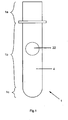
- Fig. 1 illustrates a preform (1) made of a single material where the neck region (1a), the lateral wall region (1b) and the bottom region (1c) are indicated.
- incomplete preform designates a preform that is only partially formed and comprises at least one empty volume that may be subsequently filled by at least one other material before the preform is blown into a bottle.
- the empty volume may extend through the whole thickness of the preform wall (in this case it can be designated as a hole), but it is preferred that the volume does not extend through the whole thickness of the wall, and in this case it can be designated as a recess.
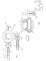
- a first molten plastic material (4) is injected through an injection nozzle (6) in a first mold cavity (8).
- This mold cavity (8) is limited on the outside by a first preform mold (10) and on the inside by an inner cylindrical core rod (12) positioned centrally inside the preform mold.
- the first injection nozzle has a center axis (not represented in this figure for clarity of the sketches), which in this example is coaxial with the cylindrical core rod.
- This first mold cavity is adapted to leave at least one volume (14) in the resulting preform (15) empty after the first material has been completely injected.
- This preform, comprising at least one empty volume is designated herein as an "incomplete" preform (15).
- first mold cavity adapted to leave at least one volume (14) in the resulting preform empty after the first material has been completely injected.
- the inside of the first preform mold may comprise one (or more) protruding volumes of mold material (which may be stainless steel) that will leave by in-print one (or more) corresponding empty volume in the resulting, incomplete preform (15).
- mold material which may be stainless steel
- the first preform mold may then be opened. The core rod and the incomplete preform (15) sitting on it may be rotated to the second injection station (16).
- the second injection station (16) may comprise a second preform cavity (18) formed by the space between an inner core rod (12) and a second preform mold (20), said second preform cavity being adapted to allow the injection-molding of the second molten material to fill-in said at least one empty volume (14).
- the second material (22) is injected in a molten state through a different injection nozzle (24) having a second center axis into the empty volume(s) (14) to (at least partially) complete the incomplete preform (15).
- the center axis of the first injection nozzle and the center axis of the second injection nozzle are not coaxial.
- the respective temperatures of the first and second materials at the time of injection of the second material are conducive to effective bonding of the materials. This can be easily determined by simple iterative experimentation.
- the first and second injection steps may be performed in the same preform mold, said preform mold comprising moving elements shutting-off the one or more empty volume to be occupied by the second material during injection of the first molten material, said removable elements being then removed before step ii) so that said second molten material can be injected in the at least one empty volumes previously occupied by the removable elements.
- the first and second materials may then be injected through injection nozzles having different central axis. Usually different injection nozzles will be used, as otherwise the same nozzle must be able to move relative to the preform.
- the mold moving elements may be exchangeable, thus allowing various designs and shapes to be obtained with the same injection machine.
- non-moving, but exchangeable inserts may be used in the mold cavity of a machine to also increase the versatility of an injection machine. I
- FIG. 2 In the schematic diagram of Fig. 2 , only one empty volume (14) is represented, but it is clear to the person skilled in the art that several empty volumes in the incomplete preform may be simultaneously filled in by the second material using an injection nozzle with multiple heads.
- Injection stations optionally fitted with multi-headed injection nozzles, are commonly used in the injection-molding industry to form composite objects made of different plastic materials such as toothbrush handles or mobile phone bodies. These injection stations can be easily adapted for use in the present invention to serve as the first and/or second injection stations as described above.
- the second material (22) is different from the first material (4).
- the first material composition is not exactly the same as the second material composition.
- the first and second material have a different visual appearance.
- the first and second materials may contain different pigments, or one material may be untinted whilst the other material comprises a pigment.
- first material and the second material have similar physical properties so that the second material "welds" properly to the first material when injected and that the preform is not prone to cracks when subsequently blown.
- first and second materials are preferably of the same plastic type.
- Non limiting examples of usual thermoplastic material that can be used as first and second materials are: polyethylene terephthalate (PET), polypropylene (PP), polyethylene naphthalate (PEN), glycol-modified polyethylene terephthalate - (PETG), polycyclohexylenedimethylene terephthalate (PCT), glycol-modified polycyclohexylenedimethylene terephthalate (PCTG), acid-modified polycyclohexylenedimethylene terephthalate (PCTA), bisphenol-A polycarbonate, blends of polyesters with bisphenol-A polycarbonate, polyester-based elastomers, polyethylene (including low-density polyethylene, medium-density polyethylene and high-density polyethylene), ethylene propylene, copolymer resin, ethylene vinyl acetate copolymer resin, other polyolefin resins, polyamide resins, ionomer resins, ABS resins, polyvinylchloride, other synthetic resins,
- Preferred materials are polyethylene terephthalate (PET), polypropylene (PP), polyethylene naphthalate (PEN), glycol-modified polyethylene terephtalate (PETG), polycyclohexylenedimethylene terephthalate (PCT), glycol-modified polycyclohexylenedimethylene terephthalate (PCTG), acid-modified polycyclohexylenedimethylene terephthalate (PCTA), bisphenol-A polycarbonate, blends of polyesters with bisphenol-A polycarbonate, polyester-based elastomers, low density polyethylene (LDPE), linear low density polyethylene (LLDPE), high density polyethylene (HDPE), and mixtures thereof.
- PET polyethylene terephthalate
- PP polypropylene
- PEN polyethylene naphthalate
- PET glycol-modified polyethylene terephtalate
- PCT polycyclohexylenedimethylene terephthalate
- PCTG glycol-modified polycycl
- polyethylene terephtalate PET
- polypropylene PP
- polyethylene naphthalate PEN
- glycol-modified polyethylene terephthalate PETG
- polycyclohexylenedimethylene terephthalate PCT
- glycol-modified polycyclohexylenedimethylene terephthalate PCTG
- acid-modified polycyclohexylenedimethylene terephthalate PCTA
- bisphenol-A polycarbonate blends of polyesters with bisphenol-A polycarbonate, and mixtures thereof.
- GB2,191,145 , Fig. 7 provides a compatibility table for common plastic materials in an extrusion (not injection) context. However it is believed that this table may be useful to select materials in the present invention. PETG is found to provide excellent results in terms of strength of the welding line (the boundaries between the materials).
- the empty volume does not extend through the whole thickness of the preform, in other word that the empty volume forms a recess.
- this recess is at the external surface of the preform.
- the first material is injected in the bottom region of the preform to make an incomplete preform having a recess on the external surface of the lateral wall region of the preform, and the second material is injected somewhere in the lateral wall of the preform to fill said recess and complete the preform.
- the bottom region of the preform is then preferably entirely made of the first material.
- the preform may be totally completed after injection of the second material, but it is also envisaged that the preform may only be partially completed after the injection of the second material, for example in embodiments wherein a third or more materials are further injected in the remaining empty volumes.
- the second preform mold (20) is opened and the core rod (12), on which the completed preform (26) sits, is rotated to a removing section (28) where the completed preform is safely removed from the core rod (12).
- the core rod may be rotated back to the first preform mold to start a new cycle.
- the completed preform can now be (stretch) blow-molded to form a bottle.
- the completed preforms can be (stretch) blow-molded in the same manufacturing site or can be stored and subsequently transported in bulk to a specialized blow-molding site.
- a standard stretch blow molding process for normal preform may be used.
- the completed preforms (26) may be placed on a preform conveyor (30) and reheated by a heating unit (32) to make them more stretchable, then placed on a conventional stretch rod (34) in a blow-mold cavity (36).
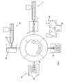
- Fig. 4 illustrates a four stages process that is similar but more automatic than the process described in Figs. 2-3 .
- the first injection and second injection stages may be carried out in a similar manner as discussed in Fig. 2 with similar injection stations (2, 16).
- the completed preform (26), whilst sitting on the core rod, may then be directly rotated to a blow-mold station (40) after the second injection station.
- Compressed air or another gas may then be passed through one or more valves in the core rod (12) to inflate the preform body so that it takes the shape of the blow mold (36).
- the core rod (12) may also be retracted and a stretch rod adapted to stretch blow-molding inserted in the preform through its neck.
- the blow-mold may then be opened and the finished bottle (38) ejected in an ejection station (42).
- the core rod may then be rotated back to the first injection station (2) and a new cycle can begin.
- the machine may comprise up to four core rods so that the injection steps, the blow step and the ejection step may take place simultaneously with different preforms/bottles.
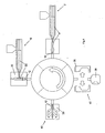
- Fig. 5 is another example of a four stage process illustrating the present invention.
- the completed preform (26) obtained after the second injection station (16) is rotated to a conditioning station (44) comprising heaters (46) where the completed preform is re-heated prior to the blow-molding stage in a blow-molding and ejection station (48).
- the finished bottle (38) is finally ejected from the blow-mold (40).
- Figs. 4 and 5 are advantageous because the preforms are immediately transformed into finished products.
- the machines used for these processes are more complex than the machines that may be used for a 2-steps process such as illustrated in Figs. 2-3 where the injection and blow-molding stages are carried out on different machines.
- the distribution of the first and second materials in the completed preforms may be well controlled by the shape of the preform molds used, and the preforms obtained may be reproduced with great consistency. Furthermore, the boundaries between the first and second materials are precise. This result was not obtainable by the process disclosed in prior art document WO97/21539 , and the preforms obtainable according to the processes claimed are believed to be new.
- injection the second material through a second nozzle may increase the cost of the machine but enables a larger choice of distribution of the first material into the second material, in particular to obtain inclusions on the side walls of the bottles such as shown on Figs. 6 to 11 .
- Using a second mold for the injection of the second material is also possible.
- the first material and the second material may be distributed in various shapes and forms relative to each other, as illustrated on Figs. 6 to 11 .
- the shapes that the second material may take include squares, rectangles, rectangles with round corners, circles or ovals, letters, words, etc.
- Fig. 6 shows an example of a bottle having multiple inclusions of the second material (22) in a continuous matrix made of a first material (4).
- Fig. 7 graduations are formed by the second material (22), facilitating a more exact reading of the proportion of content left in the bottle if the second material is transparent.
- Fig. 8 shows a bottle with a broad colour panel that could be used to frame a label.
- Fig. 9 shows a curved bottle wherein the second material is distributed in areas of the bottle where it would be difficult to apply a label using standard means.
- Fig. 10 illustrates how the preform and bottle may show letters or logo.
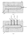
- Fig. 11 illustrates a preform where several rings of the second material are inserted in the external surface of the lateral wall of the preform.
- the rings illustrated are wavy, but they could also be straight.
- Fig. 12 is a schematic cross-section diagram of a preform as shown on Fig. 6 .
- Fig. 13 is a schematic cross-section diagram of a preform as shown on Fig. 11 .
- Fig. 14 is a schematic cross-section of a first preform mold useful for making a preform as shown on Figs. 6 and 12 with the first material completely injected in the first mold cavity.
- the empty volumes (14), which are three in this instance, are left empty after the injection of the first material.
- the first center (54) axis of the first nozzle (6) is in this instance coaxial with the central axis of the inner core rod (12), although this is not always necessary in the present invention.
- Fig. 15 is a schematic cross-section of a first preform mold useful for making a preform as shown on Figs. 6 and 12 with the second material being completely injected in the second mold cavity.
- the second center axis (56a, 56b, 56c) of each second injection nozzle (24a, 24b, 24c) are not coaxial with the first center axis (54) of the first injection nozzle.
- Fig. 16 is a schematic cross-section of a first preform mold useful for making a preform as shown on Figs. 11 and 13 with the first material completely injected in the first mold cavity.
- Fig. 17 is a schematic cross-section of a first preform mold useful for making a preform as shown on Figs. 11 and 13 with the second material being completely injected in the second mold cavity.
- the first center axis (54) of the first injection nozzle (6) is not coaxial with the center axis of any of the second center axis (56a, 56b, 56c) of the second injection nozzles (24a, 24b, 24c).
- the processes according to the invention are adapted to produce preforms and bottles made of two materials or more, wherein said materials have a precise and reproducible distribution in the bottle.
- the required preform and blow-mold can be designed using computer simulations, e.g. with Finite Element Analysis (FEA) tools.
- FEA Finite Element Analysis
- the bottles shown on Fig. 6 - 11 illustrate the type of results that may be obtained by blowing the preforms shown on the right hand side.
- the injection point of the first material (50) and the injection point of the second material (52) are situated in different regions of the preform. Having different injection points for both materials allows more sophisticated repartition of materials of the preforms, for example it is this possible to obtain inclusion of the second material in the lateral wall of the preform, as illustrated in Fig. 2 , which was not disclosed in the prior art.
- the injection point of the first material (50) and the injection point of the second material (52) are both at the surface of the completed preform.
- the injection point of the first material (50) and the injection point of the second material (52) are at least 5mm, preferably 10mm apart from one another.
- Figs. 12 and 13 illustrate preforms wherein the injection point of the first material (50) is in the bottom region of the completed preform and the injection point of the second material (52a, 52b, 52c) are in the lateral wall of the completed preform.
- the first and second materials may or may not be distributed in superposed horizontal layers.
- the second material may or may not extend through the whole thickness of the wall but it is preferred that it only fills a recess in the lateral wall region of the preform where it does not extend through the whole thickness of the wall.
- the composite preforms and bottles may even have additional functions: for example, if the first material (4) is opaque while the second material (22) is transparent, the user may be able to look through the second material to see how much of the content is left in the bottle without opening it.
- the first or second material may contain thermochromic colorants such that the parts of the bottle or perform molded with said thermochromic colorants change color when exposed to changes in temperature. These color changes may be reversible or irreversible depending on the colorant used.
- the bottles according to the invention may also be useful as anti-counterfeiting measures against rogue traders. Counterfeiting of high value goods such as cosmetics is a growing problem and counterfeiters would find it more difficult to copy a bottle with two built-in materials of different colors. If it is preferred that the bottle has only one overall color, another possibility is to use a first and a second materials having the same color in normal conditions, but add a UV reactive agent in one of the material. The UV reactive agent glows when illuminated by a proper UV lamp, which could be a hand-held detector, similarly to what is used for detecting counterfeit bank notes. This would ease counterfeit controls in places such as customs or marketplaces.
Landscapes
- Engineering & Computer Science (AREA)
- Mechanical Engineering (AREA)
- Manufacturing & Machinery (AREA)
- Ceramic Engineering (AREA)
- Physics & Mathematics (AREA)
- Geometry (AREA)
- Blow-Moulding Or Thermoforming Of Plastics Or The Like (AREA)
- Processing And Handling Of Plastics And Other Materials For Molding In General (AREA)
- Moulds For Moulding Plastics Or The Like (AREA)
- Injection Moulding Of Plastics Or The Like (AREA)
- Containers Having Bodies Formed In One Piece (AREA)
- Glass Compositions (AREA)
Claims (9)
- Verfahren zum Herstellen einer Vorform (26), die einen unteren Bereich (1c) und einen Seitenwandbereich (16) umfasst, zum Blasformen zu einer Flasche geeignet ist u aus mindestens einem ersten Material (4) und einem zweiten Material (22), das sich von dem ersten Material unterscheidet, hergestellt ist, wobei das Verfahren die folgenden aufeinander folgenden Schritte umfasst:i) Bilden einer unvollständigen Vorform (15) durch Spritzgießen eines ersten Materials (4) in einen Vorform-Hohlraum (8) durch eine erste Einspritzdüse mit einer ersten Mittelachse (54), wobei der Vorform-Hohlraum (8) durch einen Raum zwischen einem Innenkemstab (12) und einer Vorform-Gießform (10) gebildet wird, wobei der Vorform-Hohlraum (8) so konfiguriert ist, dass er mindestens ein leeres Volumen (14) in der unvollständigen Vorform (15) belässt, nachdem das erste Material (4) vollständig in den Vorform-Hohlraum (8) eingespritzt wurde, undii) Einspritzen des zweiten Materials (22) in das leere Volumen (14) durch eine zweite Einspritzdüse (24) mit einer zweiten Mittelachse (56),wobei die erste Mittelachse und die zweite Mittelachse nicht koaxial sind; und
dadurch gekennzeichnet, dass der Anspritzpunkt des ersten Materials im unteren Bereich der fertigen Vorform ist und der Anspritzpunkt des zweiten Materials in der Seitenwand der fertigen Vorfom ist, und dadurch, dass der untere Bereich vollständig aus dem ersten Material hergestellt ist. - Vorform (26), hergestellt aus mindestens einem ersten Material und einem zweiten Material (22), das sich von dem ersten Material unterscheidet, wobei die Vorform einen unteren Bereich (1c) und einen Seitenwandbereich (1b) umfasst, wobei der untere Bereich vollständig aus dem ersten Material hergestellt ist und der Seitenwandbereich aus dem ersten Material hergestellt ist, mit Ausnahme von mindestens einem Volumen (14), das von dem zweiten Material (22) gefüllt wird; und wobei die Vorform durch das Verfahren nach Anspruch 1 herstellbar ist.
- Vorform nach Anspruch 2, wobei der Anspritzpunkt des ersten Materials (50) und der Anspritzpunkt des zweiten Materials (52) beide auf der Oberfläche der fertigen Vorform liegen.
- Vorform nach Anspruch 2 oder 3, wobei der Anspritzpunkt des ersten Materials und der Anspritzpunkt des zweiten Materials mindestens 5 mm, vorzugsweise 10 mm voneinander entfernt sind.
- Vorform (26) nach Anspruch 5, wobei das Volumen eine Vertiefung in der Außenoberfläche der Vorform ist, die sich nicht durch die ganze Dicke der Seitenwand der Vorform erstreckt.
- Vorform nach Anspruch 6, wobei die Vertiefung, die von dem zweiten Material gefüllt wird, mindestens einen Ring an der Außenoberfläche der Vorform bildet.
- Vorform nach Anspruch 6, wobei die Vertiefung eine Form, die kein Ring ist, an der Oberfläche der Vorform bildet.
- Verfahren zum Herstellen einer Flasche, die aus einem ersten Material und einem zweiten Material, das sich von dem ersten Material unterscheidet, hergestellt ist, wobei das Verfahren den Schritt des Blasformens einer Vorform nach einem der Ansprüche 2 bis 8 umfasst.
- Flasche, die aus einem ersten Material und einem zweiten Material, das sich von dem ersten Material unterscheidet, hergestellt ist, wobei die Flasche durch Blasformen einer Vorform nach einem der Ansprüche 2 bis 8 herstellbar ist.
Priority Applications (1)
| Application Number | Priority Date | Filing Date | Title |
|---|---|---|---|
| EP05250295A EP1559530B1 (de) | 2004-02-02 | 2005-01-21 | Vorformling aus zwei oder mehreren Materialien und Verfahren zu ihrer Herstellung |
Applications Claiming Priority (5)
| Application Number | Priority Date | Filing Date | Title |
|---|---|---|---|
| EP04250540 | 2004-02-02 | ||
| EP04250540 | 2004-02-02 | ||
| EP04023789 | 2004-10-06 | ||
| EP04023789 | 2004-10-06 | ||
| EP05250295A EP1559530B1 (de) | 2004-02-02 | 2005-01-21 | Vorformling aus zwei oder mehreren Materialien und Verfahren zu ihrer Herstellung |
Publications (2)
| Publication Number | Publication Date |
|---|---|
| EP1559530A1 EP1559530A1 (de) | 2005-08-03 |
| EP1559530B1 true EP1559530B1 (de) | 2009-12-02 |
Family
ID=34809751
Family Applications (2)
| Application Number | Title | Priority Date | Filing Date |
|---|---|---|---|
| EP05250113A Withdrawn EP1559529A3 (de) | 2004-02-02 | 2005-01-12 | Vorformling aus zwei oder mehreren Materialien und Verfahren zu ihrer Herstellung |
| EP05250295A Revoked EP1559530B1 (de) | 2004-02-02 | 2005-01-21 | Vorformling aus zwei oder mehreren Materialien und Verfahren zu ihrer Herstellung |
Family Applications Before (1)
| Application Number | Title | Priority Date | Filing Date |
|---|---|---|---|
| EP05250113A Withdrawn EP1559529A3 (de) | 2004-02-02 | 2005-01-12 | Vorformling aus zwei oder mehreren Materialien und Verfahren zu ihrer Herstellung |
Country Status (10)
| Country | Link |
|---|---|
| US (3) | US20050170113A1 (de) |
| EP (2) | EP1559529A3 (de) |
| JP (2) | JP4562739B2 (de) |
| KR (2) | KR100808038B1 (de) |
| CN (2) | CN1914018B (de) |
| AT (1) | ATE450356T1 (de) |
| AU (2) | AU2005210651B2 (de) |
| CA (2) | CA2554319A1 (de) |
| DE (1) | DE602005017955D1 (de) |
| WO (2) | WO2005075173A1 (de) |
Families Citing this family (67)
| Publication number | Priority date | Publication date | Assignee | Title |
|---|---|---|---|---|
| EP1559529A3 (de) * | 2004-02-02 | 2005-10-19 | The Procter & Gamble Company | Vorformling aus zwei oder mehreren Materialien und Verfahren zu ihrer Herstellung |
| US20060165930A1 (en) * | 2005-01-24 | 2006-07-27 | Easterday Dyke T | Injection-molding process and apparatus using blow-mold resin |
| US20080251492A1 (en) * | 2005-03-15 | 2008-10-16 | Colgate-Palmolive Company | Overmolded Containers With Improved Gripping and Methods of Manufacture Thereof |
| DE602006007336D1 (de) * | 2005-03-15 | 2009-07-30 | Colgate Palmolive Co | Umspritzte behälter und verfahren zu deren herstellung |
| US8734923B2 (en) * | 2005-03-15 | 2014-05-27 | Colgate-Palmolive Company | Blow molded polyester container with an over-molded thermoplastic layer |
| US7694734B2 (en) * | 2005-10-31 | 2010-04-13 | Baker Hughes Incorporated | Method and apparatus for insulating a resonator downhole |
| HUE029456T2 (en) * | 2006-05-04 | 2017-03-28 | Resilux | Preform and storage device for radiation sensitive products, and a method for producing it |
| US20080118686A1 (en) * | 2006-11-20 | 2008-05-22 | Katherine Glasgow | Injection blow molding process and article |
| JP5029879B2 (ja) * | 2007-01-31 | 2012-09-19 | 株式会社吉野工業所 | 合成樹脂ブロー成形容器及びその成形方法 |
| USD608207S1 (en) | 2007-05-27 | 2010-01-19 | Colgate - Palmolive Company | Container |
| DE102007029508A1 (de) * | 2007-06-25 | 2009-01-08 | Andreas Brenner | Verfahren und Vorrichtung zur Herstellung eines Hohlkörperproduktes mit aufgespritzter zweiter Komponente |
| USD608212S1 (en) | 2007-06-27 | 2010-01-19 | Colgate-Palmolive Company | Container |
| USD597842S1 (en) | 2007-06-27 | 2009-08-11 | Colgate-Palmolive Company | Container with closure |
| USD583244S1 (en) | 2007-06-27 | 2008-12-23 | Colgate-Palmolive Company | Container |
| USD589810S1 (en) | 2007-06-27 | 2009-04-07 | Colgate-Palmolive Company | Container and closure |
| USD587127S1 (en) | 2007-06-27 | 2009-02-24 | Colgate-Palmolive Company | Container |
| US20090162589A1 (en) * | 2007-12-20 | 2009-06-25 | Karl Buchanan | Polyester compositions having reduced gas permeation and methods for their production |
| WO2009098674A2 (en) * | 2008-02-09 | 2009-08-13 | Alan Joseph Bauer | Pet preform for a transiently-extant drink bottle |
| BE1018460A5 (nl) * | 2008-02-12 | 2010-12-07 | Resilux | Kleurvoorvorm en werkwijze voor het vervaardigen hiervan tot een polychromatische kunststofbehouder. |
| US8212226B2 (en) * | 2008-03-13 | 2012-07-03 | Rexam Healthcare Packaging Inc. | Plastic container and method of manufacture having molded-in-security features |
| JP5262313B2 (ja) * | 2008-06-06 | 2013-08-14 | 凸版印刷株式会社 | ブロー成型容器 |
| JP5385383B2 (ja) | 2008-07-21 | 2014-01-08 | ベクトン・ディキンソン・アンド・カンパニー | 密度相分離装置 |
| EP2527039B1 (de) | 2008-07-21 | 2015-06-24 | Becton Dickinson and Company | Dichtephasentrennvorrichtung |
| EP2326421B1 (de) | 2008-07-21 | 2012-06-20 | Becton, Dickinson and Company | Dichte-phasentrennvorrichtung |
| JP5273528B2 (ja) * | 2008-07-31 | 2013-08-28 | 株式会社吉野工業所 | 合成樹脂製容器及びその成形方法 |
| MY196859A (en) | 2009-05-15 | 2023-05-05 | Becton Dickinson Co | Density phase separation device |
| JP5365916B2 (ja) * | 2009-05-29 | 2013-12-11 | 株式会社吉野工業所 | 合成樹脂製厚肉成形品 |
| GB0914702D0 (en) * | 2009-08-22 | 2009-09-30 | Reckitt Benckiser Nv | Method |
| DE102010003350A1 (de) | 2010-03-26 | 2011-09-29 | Krones Ag | Verfahren zum Herstellen von Kunststoffbehältern |
| DE102010036103B4 (de) * | 2010-09-01 | 2018-11-08 | Inotech Kunststofftechnik Gmbh | Mehrkomponenten-Spritzgussverfahren zur Herstellung eines hülsenförmigen Vorformlings und Vorformling |
| DE102010055822B4 (de) * | 2010-12-23 | 2013-09-26 | Inotech Kunststofftechnik Gmbh | Maschine und Verfahren zum Spritzblasen von Mehrkomponenten-Vorformlingen |
| EP2554353B1 (de) * | 2011-08-05 | 2017-06-07 | Trisa Holding AG | Verfahren zur Herstellung einer Zahnbürste und Zahnbürste |
| US9463593B2 (en) | 2011-11-22 | 2016-10-11 | The Procter & Gamble Company | Method for producing a toothbrush having an inner cavity |
| US9510664B2 (en) | 2011-11-22 | 2016-12-06 | The Procter & Gamble Co | Toothbrush having an inner cavity |
| IN2014DN03460A (de) * | 2011-11-22 | 2015-06-05 | Procter & Gamble | |
| US9756931B2 (en) | 2011-11-22 | 2017-09-12 | The Procter & Gamble Company | Method for producing a toothbrush having an inner cavity |
| US9420877B2 (en) | 2011-11-22 | 2016-08-23 | The Procter & Gamble Company | Method for producing a toothbrush having an inner cavity |
| MX2014010081A (es) | 2012-02-24 | 2015-03-10 | Procter & Gamble | Sistema de moldeo por coinyeccion con alta conductividad termica. |
| USD730735S1 (en) * | 2012-10-04 | 2015-06-02 | Stout Brands, LLC | Beverage container |
| BE1020911B1 (nl) * | 2012-11-30 | 2019-09-16 | Resilux | Werkwijze van overmoulding, i.h.b. bij voorvormelingen bestemd om omgevormd te worden tot behouders. |
| JP6115853B2 (ja) * | 2012-11-30 | 2017-04-19 | 株式会社吉野工業所 | 2軸延伸ブロー成形容器、その容器用プリフォーム及びそのプリフォームの射出成形装置 |
| MX2015015633A (es) | 2013-05-13 | 2016-03-11 | Procter & Gamble | Sistema de moldeo por inyeccion a presion baja constante con cavidades de moldeo de posicion variable. |
| JP6415902B2 (ja) * | 2014-08-28 | 2018-10-31 | 株式会社吉野工業所 | プリフォーム及びボトルの製造方法 |
| US9694359B2 (en) | 2014-11-13 | 2017-07-04 | Becton, Dickinson And Company | Mechanical separator for a biological fluid |
| US9802347B2 (en) | 2015-02-02 | 2017-10-31 | Colgate-Palmolive Company | Method of forming an oral care implement |
| US20160263798A1 (en) * | 2015-03-09 | 2016-09-15 | Li-Mei Liu | Process of manufacturing cap of a cosmetic container by injection molding twice |
| USD777446S1 (en) | 2015-07-23 | 2017-01-31 | Colgate-Palmolive Company | Oral care implement handle |
| BR112018000828A2 (pt) | 2015-07-23 | 2018-09-04 | Colgate-Palmolive Company | instrumento para higiene bucal |
| US20190315018A1 (en) | 2016-11-18 | 2019-10-17 | Husky Injection Molding Systems Ltd. | Molded article, container and a method for the molding and recycling thereof |
| FR3069182A1 (fr) | 2017-07-21 | 2019-01-25 | Ublo | Machine de fabrication d'articles en plastique par soufflage. |
| US11040475B2 (en) | 2017-09-08 | 2021-06-22 | Graham Packaging Company, L.P. | Vertically added processing for blow molding machine |
| EP3470195A1 (de) | 2017-10-12 | 2019-04-17 | The Procter & Gamble Company | Blasgeformter artikel mit visuellen effekten |
| KR101900382B1 (ko) | 2017-11-28 | 2018-09-20 | 주식회사 정민 | 이중 화장품용기의 제조방법 |
| CN111629879B (zh) * | 2018-01-23 | 2022-05-10 | 弗伯哈(德国)有限公司 | 注射成型设备 |
| US11046473B2 (en) | 2018-07-17 | 2021-06-29 | The Procter And Gamble Company | Blow molded article with visual effects |
| US11518077B2 (en) * | 2018-08-30 | 2022-12-06 | Husky Injection Molding Systems Ltd. | Molding apparatus and methods |
| CN112867674B (zh) | 2018-10-19 | 2023-07-04 | 宝洁公司 | 吹塑多层制品 |
| MX2021012431A (es) | 2019-04-11 | 2021-11-12 | Procter & Gamble | Articulo moldeado por soplado con efectos visuales. |
| US11975522B2 (en) * | 2020-01-08 | 2024-05-07 | The Procter & Gamble Company | Blow molded multilayer article with color gradient |
| DE102020101724A1 (de) * | 2020-01-24 | 2021-07-29 | Sikora Aktiengesellschaft | Vorrichtung und Verfahren zum Bestimmen der Temperatur eines rohrförmigen Strangs |
| CN111421741B (zh) * | 2020-03-11 | 2022-10-04 | 宣城托新精密科技有限公司 | 汽车内饰件加工用双色注塑喷涂装置及方法 |
| JP7498027B2 (ja) * | 2020-06-09 | 2024-06-11 | メビウスパッケージング株式会社 | 合成樹脂製容器、及びプリフォーム、並びに射出成形システム |
| CN112238572B (zh) * | 2020-08-27 | 2023-03-14 | 山东高速交通装备有限公司 | 一种含嵌件复合材料轨枕的注射成型设备及使用方法 |
| JP7721930B2 (ja) * | 2021-03-09 | 2025-08-13 | 東洋製罐株式会社 | 合成樹脂製容器 |
| CN115256872B (zh) * | 2022-03-17 | 2023-11-17 | 鹿啄泉矿泉水有限公司 | 具有颜色渐变效果的瓶体以及瓶坯成型工艺 |
| EP4585385A1 (de) * | 2022-09-06 | 2025-07-16 | Nissei ASB Machine Co., Ltd. | Vorrichtung und verfahren zur herstellung eines harzbehälters |
| CN117445313A (zh) * | 2023-10-30 | 2024-01-26 | 柳州市精业机器有限公司 | 一种热流道组件及具有其的中空成型机 |
Family Cites Families (33)
| Publication number | Priority date | Publication date | Assignee | Title |
|---|---|---|---|---|
| US3343568A (en) * | 1965-02-23 | 1967-09-26 | Phillips Petroleum Co | Extruded tubular article with clear stripe and translucent to opaque body |
| US4109813A (en) * | 1973-03-21 | 1978-08-29 | Valyi Emery I | Composite plastic container |
| JPS5167361A (en) * | 1974-12-06 | 1976-06-10 | Yoshino Kogyosho Co Ltd | Tatejimamoyoo jusuru burooseikeiseihinto sonoburooseikeiki |
| US4109579A (en) * | 1976-10-29 | 1978-08-29 | Carter Pol Development Corp. | Practice ammunition device |
| JPS5928451B2 (ja) * | 1976-12-28 | 1984-07-13 | 株式会社吉野工業所 | 多色の横縞模様壜体成形方法 |
| AU537385B2 (en) * | 1979-07-19 | 1984-06-21 | Yoshino Kogyosho Co., Ltd. | Moulding elongated parison with integral plug |
| AU6757187A (en) * | 1986-01-22 | 1987-07-23 | Retief, C.T. | Closure for a container |
| JPH0611516B2 (ja) * | 1986-06-04 | 1994-02-16 | エクセル株式会社 | 部分的に組成の異なる中空成形品及びその製造装置 |
| JPS63114604A (ja) * | 1986-10-31 | 1988-05-19 | Dainippon Printing Co Ltd | 壜口部の成形方法 |
| JP2544615B2 (ja) * | 1987-03-27 | 1996-10-16 | 大日本印刷株式会社 | 二軸延伸ブロ−成形用パリソン及びその成形方法 |
| JP2513227B2 (ja) * | 1987-04-30 | 1996-07-03 | ソニー株式会社 | 二色成形金型装置 |
| NL8702312A (nl) * | 1987-09-28 | 1989-04-17 | Holland Colours Apeldoorn Bv | Gekleurde houder uit polyester alsmede voorvorm voor een dergelijke gekleurde houder en een werkwijze voor het vervaardigen van een gekleurde polyester houder. |
| JPH0298409A (ja) * | 1988-10-04 | 1990-04-10 | Toyo Seikan Kaisha Ltd | 着色多層容器とその製造方法 |
| JPH0376624A (ja) * | 1989-08-18 | 1991-04-02 | Kamaya Kagaku Kogyo Co Ltd | 容器の射出形成方法及び容器の射出成形装置及び容器 |
| JPH03111243A (ja) * | 1989-09-14 | 1991-05-13 | Kyoraku Co Ltd | 異色材料の帯部を有する中空体 |
| JP2999226B2 (ja) * | 1990-06-19 | 2000-01-17 | 大日本印刷株式会社 | 二軸延伸ブロー成形容器の予備成形体の製造方法 |
| JPH0457732A (ja) * | 1990-06-25 | 1992-02-25 | Dainippon Printing Co Ltd | 耐熱ガスバリヤー性を有する二軸延伸ブロー成形容器 |
| US5400911A (en) * | 1992-07-01 | 1995-03-28 | Mahajan; Gautam | Plastic container with cup shaped integral base stand |
| JPH06270932A (ja) * | 1993-03-15 | 1994-09-27 | Meihoo:Kk | ポリエステル成形ボトル及びその製造方法と装置並びにインサート・ピース |
| DE4330451A1 (de) * | 1993-09-09 | 1995-03-16 | Werner Froer | Verfahren zur Herstellung eines spritzgegossenen Körpers und Spritzgußkörper |
| FR2730183B1 (fr) * | 1995-02-07 | 1997-03-14 | Oreal | Procede d'obtention d'un recipient comportant des bandes decoratives, machine de coextrusion pour la mise en oeuvre du procede et recipient obtenu par ce procede |
| US6217818B1 (en) * | 1995-07-07 | 2001-04-17 | Continental Pet Technologies, Inc. | Method of making preform and container with crystallized neck finish |
| US5595799A (en) * | 1995-12-14 | 1997-01-21 | Dtl Technology Limited Partnership | Coinjection molding of decorative preforms and containers produced from such preforms |
| US5965081A (en) * | 1996-05-16 | 1999-10-12 | The Coca-Cola Company | Method of making side-gated preforms for use in blow molding plastic bottles |
| FR2754245B1 (fr) * | 1996-10-07 | 1998-11-27 | Oreal | Recipient a bande(s) de couleur et/ou d'aspect differents |
| US6322738B1 (en) * | 1997-07-24 | 2001-11-27 | Husky Injection Molding Systems Ltd. | Method of injection over-molding articles |
| US6352426B1 (en) * | 1998-03-19 | 2002-03-05 | Advanced Plastics Technologies, Ltd. | Mold for injection molding multilayer preforms |
| WO2001026881A1 (en) | 1999-10-08 | 2001-04-19 | Taisei Kako Co., Ltd. | Method of producing laminated bottles having peelable inner layer |
| US20020058114A1 (en) * | 2000-11-10 | 2002-05-16 | Sung Chien Min | Colored bottle blank and forming mold set with manufacturing process thereof |
| US6682690B2 (en) * | 2001-02-01 | 2004-01-27 | Schmalbach-Lubreca Ag | Core rod positioning method |
| US6740283B2 (en) * | 2001-06-05 | 2004-05-25 | Inoac Packaging Group Inc. | Molding system and related method using a side-gated injection mold with vacuum assist and resulting blow molded article |
| JP3996007B2 (ja) * | 2002-07-30 | 2007-10-24 | 株式会社吉野工業所 | ひび割れ模様を有する合成樹脂製容器及びその製造方法 |
| EP1559529A3 (de) * | 2004-02-02 | 2005-10-19 | The Procter & Gamble Company | Vorformling aus zwei oder mehreren Materialien und Verfahren zu ihrer Herstellung |
-
2005
- 2005-01-12 EP EP05250113A patent/EP1559529A3/de not_active Withdrawn
- 2005-01-21 EP EP05250295A patent/EP1559530B1/de not_active Revoked
- 2005-01-21 AT AT05250295T patent/ATE450356T1/de not_active IP Right Cessation
- 2005-01-21 DE DE602005017955T patent/DE602005017955D1/de not_active Expired - Lifetime
- 2005-02-01 KR KR1020067015490A patent/KR100808038B1/ko not_active Expired - Fee Related
- 2005-02-01 AU AU2005210651A patent/AU2005210651B2/en not_active Expired - Fee Related
- 2005-02-01 CN CN2005800038972A patent/CN1914018B/zh not_active Expired - Lifetime
- 2005-02-01 KR KR1020067015491A patent/KR100848520B1/ko not_active Expired - Fee Related
- 2005-02-01 WO PCT/US2005/003177 patent/WO2005075173A1/en not_active Ceased
- 2005-02-01 WO PCT/US2005/003175 patent/WO2005075172A2/en not_active Ceased
- 2005-02-01 JP JP2006552202A patent/JP4562739B2/ja not_active Expired - Lifetime
- 2005-02-01 CN CNA2005800038968A patent/CN1914017A/zh active Pending
- 2005-02-01 US US11/047,942 patent/US20050170113A1/en not_active Abandoned
- 2005-02-01 AU AU2005210653A patent/AU2005210653B8/en not_active Ceased
- 2005-02-01 JP JP2006552201A patent/JP2007521990A/ja active Pending
- 2005-02-01 CA CA002554319A patent/CA2554319A1/en not_active Abandoned
- 2005-02-01 CA CA2554358A patent/CA2554358C/en not_active Expired - Lifetime
- 2005-02-01 US US11/047,943 patent/US20050170114A1/en not_active Abandoned
-
2009
- 2009-02-02 US US12/363,975 patent/US20090194915A1/en not_active Abandoned
Also Published As
| Publication number | Publication date |
|---|---|
| EP1559529A3 (de) | 2005-10-19 |
| KR20060132675A (ko) | 2006-12-21 |
| WO2005075172A3 (en) | 2005-11-24 |
| KR100808038B1 (ko) | 2008-02-28 |
| WO2005075173A1 (en) | 2005-08-18 |
| KR20060129358A (ko) | 2006-12-15 |
| JP2007521990A (ja) | 2007-08-09 |
| CA2554319A1 (en) | 2005-08-18 |
| AU2005210651A1 (en) | 2005-08-18 |
| US20050170113A1 (en) | 2005-08-04 |
| AU2005210651B2 (en) | 2008-10-09 |
| AU2005210653A1 (en) | 2005-08-18 |
| AU2005210653B2 (en) | 2008-11-13 |
| US20090194915A1 (en) | 2009-08-06 |
| CN1914017A (zh) | 2007-02-14 |
| CA2554358A1 (en) | 2005-08-18 |
| JP2007521991A (ja) | 2007-08-09 |
| US20050170114A1 (en) | 2005-08-04 |
| EP1559530A1 (de) | 2005-08-03 |
| CN1914018A (zh) | 2007-02-14 |
| ATE450356T1 (de) | 2009-12-15 |
| EP1559529A2 (de) | 2005-08-03 |
| CA2554358C (en) | 2011-12-06 |
| WO2005075172A2 (en) | 2005-08-18 |
| KR100848520B1 (ko) | 2008-07-25 |
| CN1914018B (zh) | 2012-07-11 |
| AU2005210653B8 (en) | 2008-12-11 |
| DE602005017955D1 (de) | 2010-01-14 |
| JP4562739B2 (ja) | 2010-10-13 |
Similar Documents
| Publication | Publication Date | Title |
|---|---|---|
| EP1559530B1 (de) | Vorformling aus zwei oder mehreren Materialien und Verfahren zu ihrer Herstellung | |
| EP2276672B1 (de) | Vorformling für blasgeformten polyesterbehälter mit einer überformten thermoplastischen schicht | |
| US5759654A (en) | Multiple layer preform | |
| EP1744962B1 (de) | Verfahren zum formen eines kunststoffartikels | |
| EP0466947B1 (de) | Verfahren zum Giessen einer Struktur mit mannigfaltigen Lagern und hergestellter Behälter | |
| JPS60229730A (ja) | 合成樹脂三層缶胴の製造方法 | |
| MXPA06008668A (en) | Preforms made of two or more materials and processes for obtaining them | |
| MXPA06008667A (en) | Preforms made of two or more materials and processes for obtaining them | |
| KR20220124754A (ko) | 수지제 용기의 제조 방법, 제조 장치 및 금형 유닛 | |
| HK1152918B (en) | Preform for a blow molded polyester container with an over-molded thermoplastic layer | |
| IE72977B1 (en) | A process for molding a multiple layer structure and a container made therefrom |
Legal Events
| Date | Code | Title | Description |
|---|---|---|---|
| PUAI | Public reference made under article 153(3) epc to a published international application that has entered the european phase |
Free format text: ORIGINAL CODE: 0009012 |
|
| AK | Designated contracting states |
Kind code of ref document: A1 Designated state(s): AT BE BG CH CY CZ DE DK EE ES FI FR GB GR HU IE IS IT LI LT LU MC NL PL PT RO SE SI SK TR |
|
| AX | Request for extension of the european patent |
Extension state: AL BA HR LV MK YU |
|
| 17P | Request for examination filed |
Effective date: 20050817 |
|
| AKX | Designation fees paid |
Designated state(s): AT BE BG CH CY CZ DE DK EE ES FI FR GB GR HU IE IS IT LI LT LU MC NL PL PT RO SE SI SK TR |
|
| 17Q | First examination report despatched |
Effective date: 20051013 |
|
| R17P | Request for examination filed (corrected) |
Effective date: 20050817 |
|
| RBV | Designated contracting states (corrected) |
Designated state(s): AT BE BG CH CY CZ DE DK EE ES FI FR GB GR HU IE IS IT LI LT LU MC NL PL PT RO SE SI SK TR |
|
| GRAP | Despatch of communication of intention to grant a patent |
Free format text: ORIGINAL CODE: EPIDOSNIGR1 |
|
| GRAS | Grant fee paid |
Free format text: ORIGINAL CODE: EPIDOSNIGR3 |
|
| GRAA | (expected) grant |
Free format text: ORIGINAL CODE: 0009210 |
|
| AK | Designated contracting states |
Kind code of ref document: B1 Designated state(s): AT BE BG CH CY CZ DE DK EE ES FI FR GB GR HU IE IS IT LI LT LU MC NL PL PT RO SE SI SK TR |
|
| REG | Reference to a national code |
Ref country code: GB Ref legal event code: FG4D |
|
| REG | Reference to a national code |
Ref country code: CH Ref legal event code: EP |
|
| REG | Reference to a national code |
Ref country code: IE Ref legal event code: FG4D |
|
| REF | Corresponds to: |
Ref document number: 602005017955 Country of ref document: DE Date of ref document: 20100114 Kind code of ref document: P |
|
| REG | Reference to a national code |
Ref country code: NL Ref legal event code: T3 |
|
| PG25 | Lapsed in a contracting state [announced via postgrant information from national office to epo] |
Ref country code: LT Free format text: LAPSE BECAUSE OF FAILURE TO SUBMIT A TRANSLATION OF THE DESCRIPTION OR TO PAY THE FEE WITHIN THE PRESCRIBED TIME-LIMIT Effective date: 20091202 Ref country code: SE Free format text: LAPSE BECAUSE OF FAILURE TO SUBMIT A TRANSLATION OF THE DESCRIPTION OR TO PAY THE FEE WITHIN THE PRESCRIBED TIME-LIMIT Effective date: 20091202 Ref country code: FI Free format text: LAPSE BECAUSE OF FAILURE TO SUBMIT A TRANSLATION OF THE DESCRIPTION OR TO PAY THE FEE WITHIN THE PRESCRIBED TIME-LIMIT Effective date: 20091202 |
|
| LTIE | Lt: invalidation of european patent or patent extension |
Effective date: 20091202 |
|
| PG25 | Lapsed in a contracting state [announced via postgrant information from national office to epo] |
Ref country code: CY Free format text: LAPSE BECAUSE OF FAILURE TO SUBMIT A TRANSLATION OF THE DESCRIPTION OR TO PAY THE FEE WITHIN THE PRESCRIBED TIME-LIMIT Effective date: 20091202 Ref country code: PL Free format text: LAPSE BECAUSE OF FAILURE TO SUBMIT A TRANSLATION OF THE DESCRIPTION OR TO PAY THE FEE WITHIN THE PRESCRIBED TIME-LIMIT Effective date: 20091202 Ref country code: SI Free format text: LAPSE BECAUSE OF FAILURE TO SUBMIT A TRANSLATION OF THE DESCRIPTION OR TO PAY THE FEE WITHIN THE PRESCRIBED TIME-LIMIT Effective date: 20091202 |
|
| PG25 | Lapsed in a contracting state [announced via postgrant information from national office to epo] |
Ref country code: AT Free format text: LAPSE BECAUSE OF FAILURE TO SUBMIT A TRANSLATION OF THE DESCRIPTION OR TO PAY THE FEE WITHIN THE PRESCRIBED TIME-LIMIT Effective date: 20091202 |
|
| PG25 | Lapsed in a contracting state [announced via postgrant information from national office to epo] |
Ref country code: EE Free format text: LAPSE BECAUSE OF FAILURE TO SUBMIT A TRANSLATION OF THE DESCRIPTION OR TO PAY THE FEE WITHIN THE PRESCRIBED TIME-LIMIT Effective date: 20091202 Ref country code: BG Free format text: LAPSE BECAUSE OF FAILURE TO SUBMIT A TRANSLATION OF THE DESCRIPTION OR TO PAY THE FEE WITHIN THE PRESCRIBED TIME-LIMIT Effective date: 20100302 Ref country code: ES Free format text: LAPSE BECAUSE OF FAILURE TO SUBMIT A TRANSLATION OF THE DESCRIPTION OR TO PAY THE FEE WITHIN THE PRESCRIBED TIME-LIMIT Effective date: 20100313 Ref country code: RO Free format text: LAPSE BECAUSE OF FAILURE TO SUBMIT A TRANSLATION OF THE DESCRIPTION OR TO PAY THE FEE WITHIN THE PRESCRIBED TIME-LIMIT Effective date: 20091202 Ref country code: IS Free format text: LAPSE BECAUSE OF FAILURE TO SUBMIT A TRANSLATION OF THE DESCRIPTION OR TO PAY THE FEE WITHIN THE PRESCRIBED TIME-LIMIT Effective date: 20100402 Ref country code: PT Free format text: LAPSE BECAUSE OF FAILURE TO SUBMIT A TRANSLATION OF THE DESCRIPTION OR TO PAY THE FEE WITHIN THE PRESCRIBED TIME-LIMIT Effective date: 20100402 |
|
| PG25 | Lapsed in a contracting state [announced via postgrant information from national office to epo] |
Ref country code: MC Free format text: LAPSE BECAUSE OF NON-PAYMENT OF DUE FEES Effective date: 20100131 Ref country code: SK Free format text: LAPSE BECAUSE OF FAILURE TO SUBMIT A TRANSLATION OF THE DESCRIPTION OR TO PAY THE FEE WITHIN THE PRESCRIBED TIME-LIMIT Effective date: 20091202 Ref country code: BE Free format text: LAPSE BECAUSE OF FAILURE TO SUBMIT A TRANSLATION OF THE DESCRIPTION OR TO PAY THE FEE WITHIN THE PRESCRIBED TIME-LIMIT Effective date: 20091202 Ref country code: CZ Free format text: LAPSE BECAUSE OF FAILURE TO SUBMIT A TRANSLATION OF THE DESCRIPTION OR TO PAY THE FEE WITHIN THE PRESCRIBED TIME-LIMIT Effective date: 20091202 |
|
| REG | Reference to a national code |
Ref country code: CH Ref legal event code: PL |
|
| PLBI | Opposition filed |
Free format text: ORIGINAL CODE: 0009260 |
|
| PLAX | Notice of opposition and request to file observation + time limit sent |
Free format text: ORIGINAL CODE: EPIDOSNOBS2 |
|
| 26 | Opposition filed |
Opponent name: HENKEL AG & CO. KGAA Effective date: 20100830 |
|
| PG25 | Lapsed in a contracting state [announced via postgrant information from national office to epo] |
Ref country code: GR Free format text: LAPSE BECAUSE OF FAILURE TO SUBMIT A TRANSLATION OF THE DESCRIPTION OR TO PAY THE FEE WITHIN THE PRESCRIBED TIME-LIMIT Effective date: 20100303 Ref country code: CH Free format text: LAPSE BECAUSE OF NON-PAYMENT OF DUE FEES Effective date: 20100131 Ref country code: LI Free format text: LAPSE BECAUSE OF NON-PAYMENT OF DUE FEES Effective date: 20100131 |
|
| PG25 | Lapsed in a contracting state [announced via postgrant information from national office to epo] |
Ref country code: IE Free format text: LAPSE BECAUSE OF NON-PAYMENT OF DUE FEES Effective date: 20100121 Ref country code: DK Free format text: LAPSE BECAUSE OF FAILURE TO SUBMIT A TRANSLATION OF THE DESCRIPTION OR TO PAY THE FEE WITHIN THE PRESCRIBED TIME-LIMIT Effective date: 20091202 |
|
| PLAF | Information modified related to communication of a notice of opposition and request to file observations + time limit |
Free format text: ORIGINAL CODE: EPIDOSCOBS2 |
|
| PLBB | Reply of patent proprietor to notice(s) of opposition received |
Free format text: ORIGINAL CODE: EPIDOSNOBS3 |
|
| PG25 | Lapsed in a contracting state [announced via postgrant information from national office to epo] |
Ref country code: IT Free format text: LAPSE BECAUSE OF FAILURE TO SUBMIT A TRANSLATION OF THE DESCRIPTION OR TO PAY THE FEE WITHIN THE PRESCRIBED TIME-LIMIT Effective date: 20091202 |
|
| PG25 | Lapsed in a contracting state [announced via postgrant information from national office to epo] |
Ref country code: LU Free format text: LAPSE BECAUSE OF NON-PAYMENT OF DUE FEES Effective date: 20100121 Ref country code: HU Free format text: LAPSE BECAUSE OF FAILURE TO SUBMIT A TRANSLATION OF THE DESCRIPTION OR TO PAY THE FEE WITHIN THE PRESCRIBED TIME-LIMIT Effective date: 20100603 |
|
| PG25 | Lapsed in a contracting state [announced via postgrant information from national office to epo] |
Ref country code: TR Free format text: LAPSE BECAUSE OF FAILURE TO SUBMIT A TRANSLATION OF THE DESCRIPTION OR TO PAY THE FEE WITHIN THE PRESCRIBED TIME-LIMIT Effective date: 20091202 |
|
| PGFP | Annual fee paid to national office [announced via postgrant information from national office to epo] |
Ref country code: GB Payment date: 20131227 Year of fee payment: 10 |
|
| REG | Reference to a national code |
Ref country code: DE Ref legal event code: R103 Ref document number: 602005017955 Country of ref document: DE Ref country code: DE Ref legal event code: R064 Ref document number: 602005017955 Country of ref document: DE |
|
| RDAF | Communication despatched that patent is revoked |
Free format text: ORIGINAL CODE: EPIDOSNREV1 |
|
| PGFP | Annual fee paid to national office [announced via postgrant information from national office to epo] |
Ref country code: NL Payment date: 20140108 Year of fee payment: 10 Ref country code: DE Payment date: 20140131 Year of fee payment: 10 |
|
| PGFP | Annual fee paid to national office [announced via postgrant information from national office to epo] |
Ref country code: FR Payment date: 20131223 Year of fee payment: 10 |
|
| RDAG | Patent revoked |
Free format text: ORIGINAL CODE: 0009271 |
|
| STAA | Information on the status of an ep patent application or granted ep patent |
Free format text: STATUS: PATENT REVOKED |
|
| 27W | Patent revoked |
Effective date: 20140224 |
|
| GBPR | Gb: patent revoked under art. 102 of the ep convention designating the uk as contracting state |
Effective date: 20140224 |
|
| REG | Reference to a national code |
Ref country code: DE Ref legal event code: R107 Ref document number: 602005017955 Country of ref document: DE Effective date: 20140828 |
|
| REG | Reference to a national code |
Ref country code: CH Ref legal event code: PK Free format text: DAS DATUM DES WIDERRUFS DURCH EPA IST NICHT KORREKT |