EP1558858B1 - Support amorti hydrauliquement, en particulier destine a soutenir le moteur d'un vehicule automobile - Google Patents
Support amorti hydrauliquement, en particulier destine a soutenir le moteur d'un vehicule automobile Download PDFInfo
- Publication number
- EP1558858B1 EP1558858B1 EP03782184A EP03782184A EP1558858B1 EP 1558858 B1 EP1558858 B1 EP 1558858B1 EP 03782184 A EP03782184 A EP 03782184A EP 03782184 A EP03782184 A EP 03782184A EP 1558858 B1 EP1558858 B1 EP 1558858B1
- Authority
- EP
- European Patent Office
- Prior art keywords
- supporting arm
- working chamber
- support arm
- hydraulically damped
- damped mounting
- Prior art date
- Legal status (The legal status is an assumption and is not a legal conclusion. Google has not performed a legal analysis and makes no representation as to the accuracy of the status listed.)
- Expired - Lifetime
Links
Images




Classifications
-
- F—MECHANICAL ENGINEERING; LIGHTING; HEATING; WEAPONS; BLASTING
- F16—ENGINEERING ELEMENTS AND UNITS; GENERAL MEASURES FOR PRODUCING AND MAINTAINING EFFECTIVE FUNCTIONING OF MACHINES OR INSTALLATIONS; THERMAL INSULATION IN GENERAL
- F16F—SPRINGS; SHOCK-ABSORBERS; MEANS FOR DAMPING VIBRATION
- F16F13/00—Units comprising springs of the non-fluid type as well as vibration-dampers, shock-absorbers, or fluid springs
- F16F13/04—Units comprising springs of the non-fluid type as well as vibration-dampers, shock-absorbers, or fluid springs comprising both a plastics spring and a damper, e.g. a friction damper
- F16F13/06—Units comprising springs of the non-fluid type as well as vibration-dampers, shock-absorbers, or fluid springs comprising both a plastics spring and a damper, e.g. a friction damper the damper being a fluid damper, e.g. the plastics spring not forming a part of the wall of the fluid chamber of the damper
- F16F13/08—Units comprising springs of the non-fluid type as well as vibration-dampers, shock-absorbers, or fluid springs comprising both a plastics spring and a damper, e.g. a friction damper the damper being a fluid damper, e.g. the plastics spring not forming a part of the wall of the fluid chamber of the damper the plastics spring forming at least a part of the wall of the fluid chamber of the damper
- F16F13/10—Units comprising springs of the non-fluid type as well as vibration-dampers, shock-absorbers, or fluid springs comprising both a plastics spring and a damper, e.g. a friction damper the damper being a fluid damper, e.g. the plastics spring not forming a part of the wall of the fluid chamber of the damper the plastics spring forming at least a part of the wall of the fluid chamber of the damper the wall being at least in part formed by a flexible membrane or the like
-
- F—MECHANICAL ENGINEERING; LIGHTING; HEATING; WEAPONS; BLASTING
- F16—ENGINEERING ELEMENTS AND UNITS; GENERAL MEASURES FOR PRODUCING AND MAINTAINING EFFECTIVE FUNCTIONING OF MACHINES OR INSTALLATIONS; THERMAL INSULATION IN GENERAL
- F16F—SPRINGS; SHOCK-ABSORBERS; MEANS FOR DAMPING VIBRATION
- F16F13/00—Units comprising springs of the non-fluid type as well as vibration-dampers, shock-absorbers, or fluid springs
- F16F13/04—Units comprising springs of the non-fluid type as well as vibration-dampers, shock-absorbers, or fluid springs comprising both a plastics spring and a damper, e.g. a friction damper
- F16F13/06—Units comprising springs of the non-fluid type as well as vibration-dampers, shock-absorbers, or fluid springs comprising both a plastics spring and a damper, e.g. a friction damper the damper being a fluid damper, e.g. the plastics spring not forming a part of the wall of the fluid chamber of the damper
- F16F13/08—Units comprising springs of the non-fluid type as well as vibration-dampers, shock-absorbers, or fluid springs comprising both a plastics spring and a damper, e.g. a friction damper the damper being a fluid damper, e.g. the plastics spring not forming a part of the wall of the fluid chamber of the damper the plastics spring forming at least a part of the wall of the fluid chamber of the damper
-
- B—PERFORMING OPERATIONS; TRANSPORTING
- B60—VEHICLES IN GENERAL
- B60K—ARRANGEMENT OR MOUNTING OF PROPULSION UNITS OR OF TRANSMISSIONS IN VEHICLES; ARRANGEMENT OR MOUNTING OF PLURAL DIVERSE PRIME-MOVERS IN VEHICLES; AUXILIARY DRIVES FOR VEHICLES; INSTRUMENTATION OR DASHBOARDS FOR VEHICLES; ARRANGEMENTS IN CONNECTION WITH COOLING, AIR INTAKE, GAS EXHAUST OR FUEL SUPPLY OF PROPULSION UNITS IN VEHICLES
- B60K5/00—Arrangement or mounting of internal-combustion or jet-propulsion units
- B60K5/12—Arrangement of engine supports
Definitions
- the invention relates to a hydraulically damping bearing, which serves in particular for supporting the engine of a motor vehicle.
- the bearing is provided with a suspension spring, which is made of an elastically deformable material and supports a connectable to a support arm bearing core.
- the bearing is provided with a working chamber which is bounded by the suspension spring and can be filled with a hydraulic fluid.
- the bearing also has a compensation chamber, which is connected by an overflow channel with the working chamber.
- Hydraulic bearings combine the demands for a relatively low rigidity for high-frequency vibrations, especially in the acoustic range and a relatively high stiffness for low-frequency oscillations of relatively large amplitude. Hydraulic bearings are therefore used for supporting the motor in motor vehicles application, on the one hand to isolate acoustic vibrations in a wide range and on the other hand, for example, effectively attenuate caused by uneven bumps low-frequency vibrations of large amplitude.
- a designed as a two-chamber hydraulic bearing hydraulic damping bearing is in the US 4,946,147 described.
- the known hydraulic bearing has a limited by a suspension spring working chamber, which is separated by an intermediate plate of a compensation chamber.
- a bearing core is vulcanized, which has a receiving opening for one with the engine having associated support arm.
- an overflow channel is provided, which connects the filled with hydraulic fluid working chamber with the compensation chamber.
- the damping of the bearing is primarily caused by the inertia of the hydraulic fluid flowing under a dynamic load between the working chamber and the compensation chamber. The damping can therefore be influenced by the structural design of the overflow.
- the overflow channel shows no effect at higher frequencies when the hydraulic fluid can no longer follow the exciting vibrations.
- High-frequency vibrations therefore lead to an increase in the pressure in the working chamber, with the result that the dynamic stiffness of the bearing increases.
- the intermediate plate of the known bearing is provided with a decoupling membrane which is moved or deformed by vibrations of smaller amplitude and thereby prevents an overflow of the hydraulic fluid between the working chamber and the compensation chamber.
- vibrations of greater amplitude lead to a mechanical blockage of the decoupling membrane and thus to an overflow of hydraulic fluid through the overflow.
- the decoupling membrane thus decouples the damping of vibrations of smaller amplitude, as occur in the acoustic range, from those of greater amplitude, as they are frequently to be found in the low-frequency range.
- the invention has the object of providing a hydraulically damping bearing of the type mentioned in such a way that it is possible to achieve a relatively simple and inexpensive design.
- the bearing according to the invention is based on the knowledge to arrange the working chamber connecting the working chamber with the compensation chamber overflow channel in the support arm, by means of which the bearing is fixed, for example, to the engine of a motor vehicle.
- a simple and inexpensive construction is achieved because a separate intermediate plate for the separation of working chamber and compensation chamber and for receiving the overflow is unnecessary.
- the usually cast and releasably connected to the bearing core support arm allows different configurations of the overflow. In this way, the damping behavior of the bearing can be adjusted by replacing the support arm specifically to the particular application.
- the bearing according to the invention can thus be used for the storage of various engines, wherein only the support arm and the overflow channel integrated thereon are to be adapted. Economically cost-effective modular design is thus taken into account.
- the bearing core has a passage in which the support arm can be inserted. Inserting the support arm into the passage ensures easy replacement of the support arm. Which is through a polygonal configuration of the passage resulting positive engagement between the support arm and bearing core contributes to a reliable attachment of the support arm to the bearing core.
- the passage is preferably provided with a projection which engages positively inserted in the passage inserted support arm in a recess which on a side surface of the Support arm is arranged.
- the engaging in the passage in the recess upon insertion of the support arm projection causes a positive engagement in the longitudinal direction of the support arm, which contributes to a precise positioning of the support arm in the passage.
- the overflow channel has an inlet opening into the working chamber, an outlet opening into the compensating chamber and a flow passage connecting the inlet opening and the outlet opening, which preferably extends spirally in the support arm.
- the spiral design of the flow passage ensures a compact design a comparatively long liquid column and thus an effective damping of low-frequency vibrations and vibrations of greater amplitude.
- the inlet opening on a working chamber facing the lower surface of the support arm and the outlet opening on the end face arranged the support arm to ensure a structurally appropriate structure of the bearing. It is also expedient if the working chamber is configured rotationally symmetrical and forms a funnel tapering conically to the inlet opening.
- the hopper assures that a load applied to the suspension spring is effectively transmitted to the hydraulic fluid in the working chamber to cause the hydraulic fluid to overflow through the fluid passage in response to the frequency and amplitude of the load.
- a decoupling membrane is provided, which is accommodated in a cage introduced into the support arm, which is connected via a decoupling channel with the working chamber.
- the decoupling membrane decouples lower amplitude vibrations by moving or deforming the decoupling membrane and thereby preventing the hydraulic fluid from flowing through the transfer port.
- the leading to the decoupling membrane decoupling channel causes high frequency oscillations of smaller amplitude, the hydraulic fluid in the decoupling channel is excited to a vibration which corresponds approximately to a natural frequency of the suspension spring.
- the resulting in this way resonance results in a reduction of the dynamic stiffness in a certain frequency spectrum, which can be specifically influenced by the insulating capacity of the bearing in this frequency spectrum.
- the cage is preferably open at an upper surface of the support arm facing away from the working chamber and is preferably provided with guide surfaces for guide sections of the decoupling membrane.
- the open design of the cage on the upper surface of the support arm allows for easy insertion of the decoupling membrane into the cage.
- the guide surfaces of the cage which cooperate with the guide sections of the decoupling membrane to ensure a targeted insertion of the decoupling membrane into the cage, also contribute to a practical assembly. Furthermore, it is advantageous to provide the cage with the movement of the decoupling membrane limiting projections to ensure a predetermined oscillating movement or deformation of the decoupling membrane.
- hydraulic damping bearing serves to support the engine of a motor vehicle damping.
- the bearing has a suspension spring 10 made of an elastomeric material.
- the suspension spring 10 is arranged on a rigid base plate 50 which is made of metal, For example, aluminum, and is attached to the body of the motor vehicle. Furthermore, the suspension spring 10 is connected to a made of metal, such as aluminum, support arm 30 which is fixed to the engine of the motor vehicle.
- a bearing core 13 is vulcanized, which has a cross-sectionally approximately rectangular passage 14.
- the passage 14 of the support arm 30 is inserted.
- the passage 14 is provided with a projection, not shown, which engages positively in a recess 35 of the support arm 30.
- the recess 35 is disposed on a side surface 32 of the support arm 30, in particular Fig. 4 recognize.
- the suspension spring 10 is provided in the region of the bearing core 13 with two buffers 16, 17, which extend perpendicular to the longitudinal direction of the support arm 30.
- the buffers 16, 17 cooperate with stop surfaces of a housing, not shown, which surrounds the suspension spring 10 and is secured to the base plate 50.
- the base plate 50 is provided with tabs 53, in particular Fig. 3 recognize.
- the tabs 53 allow an exact positioning of the housing on the base plate 50 and are arranged adjacent holes 54, which can serve both for connection of the housing and for fixing the base plate 50 to the body of the motor vehicle.
- the suspension spring 10 limits a working chamber 11 which is filled with a hydraulic fluid.
- the working chamber 11 is connected by an overflow channel 36 with a compensation chamber 20.
- the compensation chamber 20 is located in the passage 14 inserted support arm 30 between an end face 31 of the support arm 30 and a flexible wall 21, which closes the passage 14 at one end.
- the configured in the support arm 30 overflow channel 36 has an opening into the working chamber 11 inlet opening 37, an outlet opening 38 opening into the compensation chamber 20 and a flow passage 39 connecting the inlet opening 37 and the outlet opening 38 with each other.
- the flow passage 39 extends spirally in the support arm 30, in particular Fig. 1 recognize.
- the inlet opening 37 is arranged on a working chamber 11 facing the lower surface 33 of the support arm 30, whereas the outlet opening 38 is located on the end face 31 of the support arm 30.
- the rotationally symmetrical configured working chamber 11 forms a funnel 12, which tapers conically to the inlet port 37.
- Vibrations of the motor which are transmitted via the support arm 30 to the suspension spring 10, or, for example, caused by unevenness in the road vibrations of the body, which are passed from the base plate 50 to the suspension spring 10, lead to deformation of the suspension spring 10, which in the working chamber 11 apply hydraulic fluid.
- the incompressible hydraulic fluid is displaced in this way through the overflow channel 36 into the compensation chamber 20.
- the inertia of the hydraulic fluid flowing through the overflow channel 36 causes a damping of the vibrations.
- Vibrations of excessive amplitude are also damped by the buffers 16, 17, which cooperate with the stop surfaces of the housing.
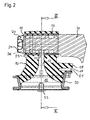
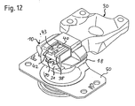
- the suspension spring 10 is provided with a projecting tongue 18 which, as in particular from Fig. 2 can be seen, is spaced by a gap 19 from a stop surface 51 of the base plate 50 and thus also buffers vibrations of excessive amplitude.
- the tongue 18 acts in the axial direction of the bearing.
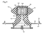
- a decoupling membrane 43 which is received in a cage 41 which is inserted into the support arm 30.
- a decoupling channel 40 leads from the inlet opening 37 to the cage 41.
- the cage 41 has a decoupling opening 42, which opens into the compensation chamber 20.
- the cage 41 on one of the working chamber 11 facing away from upper surface 34 of the support arm 30 is designed open.
- the open design of the cage 41 ensures easy insertion of the decoupling membrane 43, such as from Fig. 10 is apparent.
- the insertion of the decoupling membrane 43 is further facilitated by guide surfaces 44 of the cage 41, which, like the 10 and 11 cause a guide of guide portions 45 of the decoupling membrane 43 cause.
- the decoupling membrane 43 is deformed or moved by vibrations of smaller amplitude of the hydraulic fluid in the cage 41.
- the movement of the decoupling membrane 43 is selectively limited by projections 46 which are arranged in the cage 41.
- the decoupling membrane 43 thus contributes to a decoupling of vibrations of smaller amplitude, in which they do not lead to an overflow of the hydraulic fluid through the overflow 36.
- An overflow of the hydraulic fluid is caused by vibrations of greater amplitude, as they often occur in the low-frequency range.
- the decoupling channel 40 causes a lowering of the dynamic stiffness of the bearing. This is primarily due to the fact that the hydraulic fluid contained in the decoupling channel 40 are excited at high-frequency oscillations to resonances with natural frequencies of the suspension spring 10.
- the embodiments of a hydraulically damping bearing described above are characterized by a compact construction and a cost-effective design in terms of economy.
- the reason for this is primarily that the overflow channel 36 and the decoupling channel 40 including the cage 41 are integrated into the support arm 30.
- a separate intermediate wall for the separation of the working chamber and the compensation chamber and for receiving the overflow is thereby unnecessary.
- the interchangeable with the bearing core 13 connected support arm 30 allows a modular design of the bearing by the bearing core 13 with different designed support arms is combined. In this way it is possible, without changing the functional design of the suspension spring 10, to provide a decoupling channel 40 and a decoupling membrane 43 or various embodiments of the overflow channel 36 which decisively influences the damping behavior of the bearing.
- a simple filling of the working chamber 11 and the compensation chamber 20 with hydraulic fluid is ensured by a closable by means of a screw opening 52 in the substantially trough-shaped base plate 50.
Landscapes
- Engineering & Computer Science (AREA)
- General Engineering & Computer Science (AREA)
- Mechanical Engineering (AREA)
- Chemical & Material Sciences (AREA)
- Combustion & Propulsion (AREA)
- Transportation (AREA)
- Combined Devices Of Dampers And Springs (AREA)
- Arrangement Or Mounting Of Propulsion Units For Vehicles (AREA)
- Vehicle Body Suspensions (AREA)
- Support Of The Bearing (AREA)
Claims (10)
- Support à amortissement hydraulique, en particulier pour soutenir le moteur d'un véhicule automobile, comprenant un ressort porteur (10), qui est fabriqué en un matériau élastiquement déformable et qui soutient un noyau de support (13) relié à un bras de soutien (30), comprenant une chambre de travail (11) qui est limitée par le ressort porteur (10) et qui est remplie d'un liquide hydraulique, et comprenant une chambre de compensation (20) qui est reliée à la chambre de travail (11) via un canal de déversement (36),
caractérisé en ce que le canal de déversement (36) est intégré dans le bras de soutien (30) et le bras de soutien (30) est relié au noyau de support (13) de façon détachable et interchangeable pour l'adaptation du comportement d'amortissement. - Support à amortissement hydraulique selon la revendication 1, caractérisé en ce que le noyau de support (13) comporte une traversée (14) dans laquelle le bras de soutien (30) peut être enfiché.
- Support à amortissement hydraulique selon la revendication 2, caractérisé en ce que la traversée (14) est obturée à une extrémité par une paroi flexible (21), la chambre de compensation (20) étant limitée, lorsque le bras de soutien (30) est enfiché dans la traversée (14), par la paroi flexible (21) et par une surface frontale (31) du bras de soutien (30).
- Support à amortissement hydraulique selon la revendication 2 ou 3, caractérisé en ce que la traversée (14) est pourvu d'une saillie qui, lorsque le bras de soutien (30) est enfiché dans la traversée (14), s'engage en coopération de formes dans un évidement (35) qui est agencé sur une surface latérale (32) du bras de soutien (30).
- Support à amortissement hydraulique selon l'une des revendications 1 à 4, caractérisé en ce que le canal de déversement (36) comporte une ouverture d'entrée (37) qui débouche dans la chambre de travail (11), une ouverture de sortie (38) qui débouche dans la chambre de compensation (20), et un passage d'écoulement (39) qui relie l'une à l'autre l'ouverture d'entrée (37) et l'ouverture de sortie (38), et qui s'étend de préférence en forme de spirale dans le bras de soutien (30).
- Support à amortissement hydraulique selon la revendication 5, caractérisé en ce que l'ouverture d'entrée (37) est agencée sur une surface inférieure (33) du bras de soutien (30) tournée vers la chambre de travail (11), et l'ouverture de sortie (38) est agencée sur la surface frontale (31) du bras de soutien (30).
- Support à amortissement hydraulique selon la revendication 6, caractérisé en ce que la chambre de travail (11) est conçue à symétrie de révolution et forme un entonnoir (12) qui va en se rétrécissant de manière conique vers l'ouverture d'entrée (37).
- Support à amortissement hydraulique selon l'une des revendications 1 à 7, caractérisé en ce qu'une membrane de découplage (43) est reçue dans une cage (41) intégrée dans le bras de soutien (30) et reliée à la chambre de travail (11) via un canal de découplage (40).
- Support à amortissement hydraulique selon la revendication 8, caractérisé en ce que la cage (41) est ouverte au niveau d'une surface supérieure (34) du bras de soutien (30) détournée de la chambre de travail (11), et est de préférence pourvue de surfaces de guidage (44) pour des tronçons de guidage (45) de la membrane de découplage (43).
- Support à amortissement hydraulique selon la revendication 8 ou 9, caractérisé en ce que la cage (41) est dotée de saillies (46) qui limitent le mouvement de la membrane de découplage (43)
Applications Claiming Priority (3)
| Application Number | Priority Date | Filing Date | Title |
|---|---|---|---|
| DE10251877A DE10251877B4 (de) | 2002-11-07 | 2002-11-07 | Hydraulisch dämpfendes Lager, insbesondere zum Abstützen des Motors eines Kraftfahrzeugs |
| DE10251877 | 2002-11-07 | ||
| PCT/EP2003/012414 WO2004042250A1 (fr) | 2002-11-07 | 2003-11-06 | Support amorti hydrauliquement, en particulier destine a soutenir le moteur d'un vehicule automobile |
Publications (2)
| Publication Number | Publication Date |
|---|---|
| EP1558858A1 EP1558858A1 (fr) | 2005-08-03 |
| EP1558858B1 true EP1558858B1 (fr) | 2008-07-09 |
Family
ID=32185344
Family Applications (1)
| Application Number | Title | Priority Date | Filing Date |
|---|---|---|---|
| EP03782184A Expired - Lifetime EP1558858B1 (fr) | 2002-11-07 | 2003-11-06 | Support amorti hydrauliquement, en particulier destine a soutenir le moteur d'un vehicule automobile |
Country Status (10)
| Country | Link |
|---|---|
| US (1) | US7207552B2 (fr) |
| EP (1) | EP1558858B1 (fr) |
| JP (1) | JP2006505751A (fr) |
| KR (1) | KR20050084973A (fr) |
| CN (1) | CN100387862C (fr) |
| AT (1) | ATE400748T1 (fr) |
| AU (1) | AU2003289855A1 (fr) |
| BR (1) | BR0316063A (fr) |
| DE (2) | DE10251877B4 (fr) |
| WO (1) | WO2004042250A1 (fr) |
Families Citing this family (9)
| Publication number | Priority date | Publication date | Assignee | Title |
|---|---|---|---|---|
| USD571643S1 (en) * | 2007-02-12 | 2008-06-24 | Trelleborg Industrial Avs Ltd. | Vibration and shock absorber |
| DE102008007137A1 (de) * | 2008-01-31 | 2009-08-06 | Carl Freudenberg Kg | Hydraulisch dämpfendes Aggregatelager |
| DE102009059028A1 (de) * | 2009-12-18 | 2011-06-22 | Bayerische Motoren Werke Aktiengesellschaft, 80809 | Aggregate-Befestigungseinrichtung für Kraftfahrzeuge |
| DE102010004381A1 (de) * | 2010-01-12 | 2011-07-14 | Anvis Deutschland GmbH, 36396 | Hydro-elastisches Funktionsteil für eine Lagerung, hydro-elastische Lagerung und Verfahren zum Montieren der hydro-elastischen Lagerung |
| CN102501751A (zh) * | 2011-10-18 | 2012-06-20 | 奇瑞汽车股份有限公司 | 一种发动机液压悬置软垫总成 |
| GB201212534D0 (en) | 2012-07-13 | 2012-08-29 | Dtr Vms Ltd | Hydraulically damped mountinf device |
| WO2015029086A1 (fr) * | 2013-08-28 | 2015-03-05 | 東海ゴム工業株式会社 | Dispositif amortisseur de vibrations |
| JP6566823B2 (ja) * | 2015-09-30 | 2019-08-28 | 倉敷化工株式会社 | エンジンマウント構造 |
| FR3087157B1 (fr) * | 2018-10-12 | 2022-01-14 | Psa Automobiles Sa | Butee hydraulique a inertie de fin de course de suspension de vehicule automobile |
Family Cites Families (20)
| Publication number | Priority date | Publication date | Assignee | Title |
|---|---|---|---|---|
| US2991992A (en) * | 1960-04-11 | 1961-07-11 | Aeroquip Corp | Time delay device |
| JPS598696B2 (ja) * | 1979-12-26 | 1984-02-27 | 豊田合成株式会社 | 液封入防振装置 |
| DE3104708A1 (de) * | 1981-02-10 | 1982-08-26 | WOCO Franz-Josef Wolf & Co, 6483 Bad Soden-Salmünster | Dreikammerdaempfer |
| US4733854A (en) * | 1983-06-10 | 1988-03-29 | Honda Giken Kogyo Kabushiki Kaisha | Fluid sealed mounting |
| EP0172700B2 (fr) * | 1984-08-07 | 1992-04-22 | Avon Industrial Polymers Limited | Dispositif de montage à amortissement hydraulique |
| JPS61218845A (ja) * | 1985-03-22 | 1986-09-29 | Nissan Motor Co Ltd | 流体入りマウント装置 |
| JPH0519631Y2 (fr) * | 1985-11-28 | 1993-05-24 | ||
| DE3729563A1 (de) * | 1986-09-19 | 1988-03-31 | Phoenix Ag | Elastisches lager |
| FR2613799B1 (fr) * | 1987-04-13 | 1990-12-07 | Peugeot | Support hydroelastique, notamment pour la suspension d'un moteur de vehicule |
| JPS63266240A (ja) * | 1987-04-23 | 1988-11-02 | Mazda Motor Corp | 流体入りブツシユ |
| US5044813A (en) * | 1988-01-26 | 1991-09-03 | The Goodyear Tire & Rubber Company | Bush type hydraulically damped engine or transmission mount |
| JPH01238730A (ja) * | 1988-03-19 | 1989-09-22 | Tokai Rubber Ind Ltd | 流体封入式マウント装置 |
| DE3834099A1 (de) * | 1988-10-07 | 1990-04-12 | Phoenix Ag | Elastisches lager mit verstellbarer duesenplatte |
| FR2659712B1 (fr) * | 1990-03-16 | 1992-07-17 | Hutchinson | Perfectionnements apportes aux manchons antivibratoires hydrauliques. |
| DE4117130A1 (de) * | 1991-05-25 | 1992-11-26 | Daimler Benz Ag | Hydraulisch daempfendes lager |
| JP3537872B2 (ja) * | 1994-08-25 | 2004-06-14 | 倉敷化工株式会社 | 流体封入式エンジンマウント及びその製造方法 |
| CN2308763Y (zh) * | 1997-10-10 | 1999-02-24 | 吉林工业大学 | 发动机液压阻尼式悬置元件 |
| JPH11230240A (ja) * | 1998-02-16 | 1999-08-27 | Honda Motor Co Ltd | 液体封入ダンパーマウント |
| GB2359607B (en) * | 2000-02-24 | 2003-09-17 | Draftex Ind Ltd | Vibration damping arrangements |
| DE10064330A1 (de) * | 2000-12-21 | 2002-07-11 | Freudenberg Carl Kg | Hydrolager |
-
2002
- 2002-11-07 DE DE10251877A patent/DE10251877B4/de not_active Expired - Fee Related
-
2003
- 2003-11-06 AT AT03782184T patent/ATE400748T1/de not_active IP Right Cessation
- 2003-11-06 AU AU2003289855A patent/AU2003289855A1/en not_active Abandoned
- 2003-11-06 CN CNB2003801084343A patent/CN100387862C/zh not_active Expired - Fee Related
- 2003-11-06 DE DE50310121T patent/DE50310121D1/de not_active Expired - Fee Related
- 2003-11-06 EP EP03782184A patent/EP1558858B1/fr not_active Expired - Lifetime
- 2003-11-06 WO PCT/EP2003/012414 patent/WO2004042250A1/fr not_active Ceased
- 2003-11-06 KR KR1020057008093A patent/KR20050084973A/ko not_active Ceased
- 2003-11-06 JP JP2004549142A patent/JP2006505751A/ja active Pending
- 2003-11-06 BR BR0316063-7A patent/BR0316063A/pt not_active IP Right Cessation
-
2005
- 2005-05-09 US US11/125,552 patent/US7207552B2/en not_active Expired - Fee Related
Also Published As
| Publication number | Publication date |
|---|---|
| CN100387862C (zh) | 2008-05-14 |
| ATE400748T1 (de) | 2008-07-15 |
| WO2004042250A1 (fr) | 2004-05-21 |
| US20050225016A1 (en) | 2005-10-13 |
| DE50310121D1 (de) | 2008-08-21 |
| DE10251877A1 (de) | 2004-05-27 |
| BR0316063A (pt) | 2005-09-27 |
| CN1735760A (zh) | 2006-02-15 |
| EP1558858A1 (fr) | 2005-08-03 |
| JP2006505751A (ja) | 2006-02-16 |
| KR20050084973A (ko) | 2005-08-29 |
| AU2003289855A1 (en) | 2004-06-07 |
| DE10251877B4 (de) | 2008-08-07 |
| US7207552B2 (en) | 2007-04-24 |
Similar Documents
| Publication | Publication Date | Title |
|---|---|---|
| DE3134310C2 (de) | "Einrichtung zur Dämpfung von Schwingungen im Antriebsstrang eines Kraftfahrzeuges" | |
| EP0901707B1 (fr) | Dispositif de retenue pour moteur electrique | |
| EP1694981B1 (fr) | Coussinet assurant un amortissement hydraulique | |
| DE3246587C2 (de) | Hydraulisch dämpfendes Gummilager | |
| EP0617211A1 (fr) | Manchon élastique à amortissement hydraulique | |
| EP0611901A1 (fr) | Coussinet de palier à amortissement hydraulique | |
| EP1558858B1 (fr) | Support amorti hydrauliquement, en particulier destine a soutenir le moteur d'un vehicule automobile | |
| DE102009021994B4 (de) | Hydrolager | |
| DE102006003938A1 (de) | Hydraulisch gedämpfte Karosseriebefestigung mit durchragendem Bolzen | |
| DE102005022134A1 (de) | Vibrationsdämpfungsvorrichtung für Fahrzeuge und Verfahren zum Herstellen derselbigen | |
| DE3820805A1 (de) | Schwingungsdaempfungsvorrichtung | |
| DE10036740A1 (de) | Schwingungsdämpfungseinrichtung, deren elastischer Körper eine gute Haltbarkeit aufweist | |
| DE3920153C2 (fr) | ||
| DE4005889A1 (de) | Schwingungsdaempfer | |
| DE602005003700T2 (de) | Magnetorheologisches Fluidlager | |
| EP1084354B1 (fr) | Palier de support a deux chambres | |
| WO2014191150A1 (fr) | Support en caoutchouc d'amortissement hydraulique | |
| DE112019003332T5 (de) | Fluidgefüllte vibrationsdämpfungsvorrichtung | |
| EP0351737A2 (fr) | Support de moteur à amortissement hydraulique | |
| DE7818415U1 (de) | Elastisches Motorlager, insbesondere für Kraftfahrzeuge | |
| DE102004060499B4 (de) | Aggregatelager | |
| EP0528253B1 (fr) | Palier de support à amortissement hydraulique pour parties de châssis de voiture | |
| DE19639929C2 (de) | Fluidgefüllte zylindrische elastische Halterung mit Zwischenhülse aus Kunstharz und integral ausgebildeten Stoppern | |
| EP2059692B1 (fr) | Palier de groupe à amortissement hydraulique | |
| DE19650230B4 (de) | Mehrkammer-Hydrauliklager |
Legal Events
| Date | Code | Title | Description |
|---|---|---|---|
| PUAI | Public reference made under article 153(3) epc to a published international application that has entered the european phase |
Free format text: ORIGINAL CODE: 0009012 |
|
| 17P | Request for examination filed |
Effective date: 20050504 |
|
| AK | Designated contracting states |
Kind code of ref document: A1 Designated state(s): AT BE BG CH CY CZ DE DK EE ES FI FR GB GR HU IE IT LI LU MC NL PT RO SE SI SK TR |
|
| AX | Request for extension of the european patent |
Extension state: AL LT LV MK |
|
| DAX | Request for extension of the european patent (deleted) | ||
| 17Q | First examination report despatched |
Effective date: 20070305 |
|
| GRAP | Despatch of communication of intention to grant a patent |
Free format text: ORIGINAL CODE: EPIDOSNIGR1 |
|
| GRAS | Grant fee paid |
Free format text: ORIGINAL CODE: EPIDOSNIGR3 |
|
| GRAA | (expected) grant |
Free format text: ORIGINAL CODE: 0009210 |
|
| AK | Designated contracting states |
Kind code of ref document: B1 Designated state(s): AT BE BG CH CY CZ DE DK EE ES FI FR GB GR HU IE IT LI LU MC NL PT RO SE SI SK TR |
|
| REG | Reference to a national code |
Ref country code: GB Ref legal event code: FG4D Free format text: NOT ENGLISH |
|
| REG | Reference to a national code |
Ref country code: CH Ref legal event code: EP |
|
| REF | Corresponds to: |
Ref document number: 50310121 Country of ref document: DE Date of ref document: 20080821 Kind code of ref document: P |
|
| REG | Reference to a national code |
Ref country code: IE Ref legal event code: FG4D Free format text: LANGUAGE OF EP DOCUMENT: GERMAN |
|
| NLV1 | Nl: lapsed or annulled due to failure to fulfill the requirements of art. 29p and 29m of the patents act | ||
| PG25 | Lapsed in a contracting state [announced via postgrant information from national office to epo] |
Ref country code: NL Free format text: LAPSE BECAUSE OF FAILURE TO SUBMIT A TRANSLATION OF THE DESCRIPTION OR TO PAY THE FEE WITHIN THE PRESCRIBED TIME-LIMIT Effective date: 20080709 Ref country code: PT Free format text: LAPSE BECAUSE OF FAILURE TO SUBMIT A TRANSLATION OF THE DESCRIPTION OR TO PAY THE FEE WITHIN THE PRESCRIBED TIME-LIMIT Effective date: 20081209 Ref country code: ES Free format text: LAPSE BECAUSE OF FAILURE TO SUBMIT A TRANSLATION OF THE DESCRIPTION OR TO PAY THE FEE WITHIN THE PRESCRIBED TIME-LIMIT Effective date: 20081020 |
|
| PG25 | Lapsed in a contracting state [announced via postgrant information from national office to epo] |
Ref country code: SI Free format text: LAPSE BECAUSE OF FAILURE TO SUBMIT A TRANSLATION OF THE DESCRIPTION OR TO PAY THE FEE WITHIN THE PRESCRIBED TIME-LIMIT Effective date: 20080709 Ref country code: BG Free format text: LAPSE BECAUSE OF FAILURE TO SUBMIT A TRANSLATION OF THE DESCRIPTION OR TO PAY THE FEE WITHIN THE PRESCRIBED TIME-LIMIT Effective date: 20081009 Ref country code: FI Free format text: LAPSE BECAUSE OF FAILURE TO SUBMIT A TRANSLATION OF THE DESCRIPTION OR TO PAY THE FEE WITHIN THE PRESCRIBED TIME-LIMIT Effective date: 20080709 |
|
| REG | Reference to a national code |
Ref country code: IE Ref legal event code: FD4D |
|
| PG25 | Lapsed in a contracting state [announced via postgrant information from national office to epo] |
Ref country code: DK Free format text: LAPSE BECAUSE OF FAILURE TO SUBMIT A TRANSLATION OF THE DESCRIPTION OR TO PAY THE FEE WITHIN THE PRESCRIBED TIME-LIMIT Effective date: 20080709 Ref country code: EE Free format text: LAPSE BECAUSE OF FAILURE TO SUBMIT A TRANSLATION OF THE DESCRIPTION OR TO PAY THE FEE WITHIN THE PRESCRIBED TIME-LIMIT Effective date: 20080709 Ref country code: IE Free format text: LAPSE BECAUSE OF FAILURE TO SUBMIT A TRANSLATION OF THE DESCRIPTION OR TO PAY THE FEE WITHIN THE PRESCRIBED TIME-LIMIT Effective date: 20080709 |
|
| PLBE | No opposition filed within time limit |
Free format text: ORIGINAL CODE: 0009261 |
|
| STAA | Information on the status of an ep patent application or granted ep patent |
Free format text: STATUS: NO OPPOSITION FILED WITHIN TIME LIMIT |
|
| PG25 | Lapsed in a contracting state [announced via postgrant information from national office to epo] |
Ref country code: SK Free format text: LAPSE BECAUSE OF FAILURE TO SUBMIT A TRANSLATION OF THE DESCRIPTION OR TO PAY THE FEE WITHIN THE PRESCRIBED TIME-LIMIT Effective date: 20080709 Ref country code: CZ Free format text: LAPSE BECAUSE OF FAILURE TO SUBMIT A TRANSLATION OF THE DESCRIPTION OR TO PAY THE FEE WITHIN THE PRESCRIBED TIME-LIMIT Effective date: 20080709 |
|
| BERE | Be: lapsed |
Owner name: TRELLEBORG AUTOMOTIVE TECHNICAL CENTRE G.M.B.H. Effective date: 20081130 |
|
| 26N | No opposition filed |
Effective date: 20090414 |
|
| PG25 | Lapsed in a contracting state [announced via postgrant information from national office to epo] |
Ref country code: MC Free format text: LAPSE BECAUSE OF NON-PAYMENT OF DUE FEES Effective date: 20081130 |
|
| REG | Reference to a national code |
Ref country code: CH Ref legal event code: PL |
|
| GBPC | Gb: european patent ceased through non-payment of renewal fee |
Effective date: 20081106 |
|
| PG25 | Lapsed in a contracting state [announced via postgrant information from national office to epo] |
Ref country code: IT Free format text: LAPSE BECAUSE OF FAILURE TO SUBMIT A TRANSLATION OF THE DESCRIPTION OR TO PAY THE FEE WITHIN THE PRESCRIBED TIME-LIMIT Effective date: 20080709 |
|
| REG | Reference to a national code |
Ref country code: FR Ref legal event code: ST Effective date: 20090731 |
|
| PG25 | Lapsed in a contracting state [announced via postgrant information from national office to epo] |
Ref country code: BE Free format text: LAPSE BECAUSE OF NON-PAYMENT OF DUE FEES Effective date: 20081130 |
|
| PG25 | Lapsed in a contracting state [announced via postgrant information from national office to epo] |
Ref country code: DE Free format text: LAPSE BECAUSE OF NON-PAYMENT OF DUE FEES Effective date: 20090603 Ref country code: CH Free format text: LAPSE BECAUSE OF NON-PAYMENT OF DUE FEES Effective date: 20081130 Ref country code: LI Free format text: LAPSE BECAUSE OF NON-PAYMENT OF DUE FEES Effective date: 20081130 |
|
| PG25 | Lapsed in a contracting state [announced via postgrant information from national office to epo] |
Ref country code: GB Free format text: LAPSE BECAUSE OF NON-PAYMENT OF DUE FEES Effective date: 20081106 |
|
| PG25 | Lapsed in a contracting state [announced via postgrant information from national office to epo] |
Ref country code: SE Free format text: LAPSE BECAUSE OF FAILURE TO SUBMIT A TRANSLATION OF THE DESCRIPTION OR TO PAY THE FEE WITHIN THE PRESCRIBED TIME-LIMIT Effective date: 20081009 Ref country code: AT Free format text: LAPSE BECAUSE OF NON-PAYMENT OF DUE FEES Effective date: 20081106 |
|
| PG25 | Lapsed in a contracting state [announced via postgrant information from national office to epo] |
Ref country code: RO Free format text: LAPSE BECAUSE OF NON-PAYMENT OF DUE FEES Effective date: 20081106 |
|
| PG25 | Lapsed in a contracting state [announced via postgrant information from national office to epo] |
Ref country code: HU Free format text: LAPSE BECAUSE OF FAILURE TO SUBMIT A TRANSLATION OF THE DESCRIPTION OR TO PAY THE FEE WITHIN THE PRESCRIBED TIME-LIMIT Effective date: 20090110 Ref country code: LU Free format text: LAPSE BECAUSE OF NON-PAYMENT OF DUE FEES Effective date: 20081106 Ref country code: CY Free format text: LAPSE BECAUSE OF FAILURE TO SUBMIT A TRANSLATION OF THE DESCRIPTION OR TO PAY THE FEE WITHIN THE PRESCRIBED TIME-LIMIT Effective date: 20080709 |
|
| PG25 | Lapsed in a contracting state [announced via postgrant information from national office to epo] |
Ref country code: TR Free format text: LAPSE BECAUSE OF FAILURE TO SUBMIT A TRANSLATION OF THE DESCRIPTION OR TO PAY THE FEE WITHIN THE PRESCRIBED TIME-LIMIT Effective date: 20080709 |
|
| PG25 | Lapsed in a contracting state [announced via postgrant information from national office to epo] |
Ref country code: GR Free format text: LAPSE BECAUSE OF FAILURE TO SUBMIT A TRANSLATION OF THE DESCRIPTION OR TO PAY THE FEE WITHIN THE PRESCRIBED TIME-LIMIT Effective date: 20081010 |
|
| PG25 | Lapsed in a contracting state [announced via postgrant information from national office to epo] |
Ref country code: FR Free format text: LAPSE BECAUSE OF NON-PAYMENT OF DUE FEES Effective date: 20081130 |