EP1557543B1 - A variable capacity fluid pump for an engine - Google Patents
A variable capacity fluid pump for an engine Download PDFInfo
- Publication number
- EP1557543B1 EP1557543B1 EP05000933A EP05000933A EP1557543B1 EP 1557543 B1 EP1557543 B1 EP 1557543B1 EP 05000933 A EP05000933 A EP 05000933A EP 05000933 A EP05000933 A EP 05000933A EP 1557543 B1 EP1557543 B1 EP 1557543B1
- Authority
- EP
- European Patent Office
- Prior art keywords
- gear
- rotational speed
- fluid pump
- variable capacity
- pump
- Prior art date
- Legal status (The legal status is an assumption and is not a legal conclusion. Google has not performed a legal analysis and makes no representation as to the accuracy of the status listed.)
- Expired - Fee Related
Links
Images


Classifications
-
- F—MECHANICAL ENGINEERING; LIGHTING; HEATING; WEAPONS; BLASTING
- F01—MACHINES OR ENGINES IN GENERAL; ENGINE PLANTS IN GENERAL; STEAM ENGINES
- F01P—COOLING OF MACHINES OR ENGINES IN GENERAL; COOLING OF INTERNAL-COMBUSTION ENGINES
- F01P7/00—Controlling of coolant flow
- F01P7/14—Controlling of coolant flow the coolant being liquid
- F01P7/16—Controlling of coolant flow the coolant being liquid by thermostatic control
- F01P7/164—Controlling of coolant flow the coolant being liquid by thermostatic control by varying pump speed
-
- F—MECHANICAL ENGINEERING; LIGHTING; HEATING; WEAPONS; BLASTING
- F01—MACHINES OR ENGINES IN GENERAL; ENGINE PLANTS IN GENERAL; STEAM ENGINES
- F01M—LUBRICATING OF MACHINES OR ENGINES IN GENERAL; LUBRICATING INTERNAL COMBUSTION ENGINES; CRANKCASE VENTILATING
- F01M1/00—Pressure lubrication
- F01M1/16—Controlling lubricant pressure or quantity
-
- F—MECHANICAL ENGINEERING; LIGHTING; HEATING; WEAPONS; BLASTING
- F01—MACHINES OR ENGINES IN GENERAL; ENGINE PLANTS IN GENERAL; STEAM ENGINES
- F01P—COOLING OF MACHINES OR ENGINES IN GENERAL; COOLING OF INTERNAL-COMBUSTION ENGINES
- F01P5/00—Pumping cooling-air or liquid coolants
- F01P5/10—Pumping liquid coolant; Arrangements of coolant pumps
- F01P5/12—Pump-driving arrangements
-
- F—MECHANICAL ENGINEERING; LIGHTING; HEATING; WEAPONS; BLASTING
- F01—MACHINES OR ENGINES IN GENERAL; ENGINE PLANTS IN GENERAL; STEAM ENGINES
- F01P—COOLING OF MACHINES OR ENGINES IN GENERAL; COOLING OF INTERNAL-COMBUSTION ENGINES
- F01P7/00—Controlling of coolant flow
- F01P7/14—Controlling of coolant flow the coolant being liquid
- F01P7/16—Controlling of coolant flow the coolant being liquid by thermostatic control
- F01P7/167—Controlling of coolant flow the coolant being liquid by thermostatic control by adjusting the pre-set temperature according to engine parameters, e.g. engine load, engine speed
-
- F—MECHANICAL ENGINEERING; LIGHTING; HEATING; WEAPONS; BLASTING
- F02—COMBUSTION ENGINES; HOT-GAS OR COMBUSTION-PRODUCT ENGINE PLANTS
- F02B—INTERNAL-COMBUSTION PISTON ENGINES; COMBUSTION ENGINES IN GENERAL
- F02B67/00—Engines characterised by the arrangement of auxiliary apparatus not being otherwise provided for, e.g. the apparatus having different functions; Driving auxiliary apparatus from engines, not otherwise provided for
- F02B67/04—Engines characterised by the arrangement of auxiliary apparatus not being otherwise provided for, e.g. the apparatus having different functions; Driving auxiliary apparatus from engines, not otherwise provided for of mechanically-driven auxiliary apparatus
-
- F—MECHANICAL ENGINEERING; LIGHTING; HEATING; WEAPONS; BLASTING
- F04—POSITIVE - DISPLACEMENT MACHINES FOR LIQUIDS; PUMPS FOR LIQUIDS OR ELASTIC FLUIDS
- F04D—NON-POSITIVE-DISPLACEMENT PUMPS
- F04D13/00—Pumping installations or systems
- F04D13/02—Units comprising pumps and their driving means
- F04D13/028—Units comprising pumps and their driving means the driving means being a planetary gear
-
- F—MECHANICAL ENGINEERING; LIGHTING; HEATING; WEAPONS; BLASTING
- F01—MACHINES OR ENGINES IN GENERAL; ENGINE PLANTS IN GENERAL; STEAM ENGINES
- F01M—LUBRICATING OF MACHINES OR ENGINES IN GENERAL; LUBRICATING INTERNAL COMBUSTION ENGINES; CRANKCASE VENTILATING
- F01M1/00—Pressure lubrication
- F01M1/02—Pressure lubrication using lubricating pumps
- F01M2001/0253—Pressure lubrication using lubricating pumps characterised by the pump driving means
- F01M2001/0269—Pressure lubrication using lubricating pumps characterised by the pump driving means driven by the crankshaft
-
- F—MECHANICAL ENGINEERING; LIGHTING; HEATING; WEAPONS; BLASTING
- F16—ENGINEERING ELEMENTS AND UNITS; GENERAL MEASURES FOR PRODUCING AND MAINTAINING EFFECTIVE FUNCTIONING OF MACHINES OR INSTALLATIONS; THERMAL INSULATION IN GENERAL
- F16N—LUBRICATING
- F16N2250/00—Measuring
- F16N2250/04—Pressure
Definitions
- the present invention relates to a control for a fluid pump (an oil pump or a water pump) of an engine.
- a lubrication apparatus and a cooling apparatus are supplied with an engine.
- the lubrication apparatus is an apparatus for reducing the frictional resistance by using oil for each section of the engine.
- the lubrication apparatus uses an oil pump coupled to a crankshaft of the engine to feed oil to a lubrication passage.
- the cooling apparatus is an apparatus for keeping the temperature at which the engine can continue rotating with stability.
- the cooling apparatus feeds cooling water to a passage disposed in a cylinder block and a cylinder head of the engine to prevent the engine from overheating.
- the cooling apparatus uses a water pump coupled to the crankshaft of the engine to circulate the cooling water.
- the electrically-driven pump can control the rotation of the pump independently of the engine rotation because it utilizes the driving force of a motor for rotating the pump.
- the electrically-driven pump There are two types of the electrically-driven pump. One is a brush motor and the other is a brushless motor.
- the electrically-driven pump can control a flow rate of the pump independently of the engine rotational speed, there are some problems. If a brush motor is used, its reliability is low because it is susceptible to aging and failure due to wear of the brush. If a brushless pump is used, a PDU (power distribution unit) is required for controlling the magnetic field by the three-phase lines, which increases the weight of the pump system and hence decreases the fuel efficiency.
- a PDU power distribution unit
- a sliding mode control is known in the field of engine control.
- the sliding mode control is capable of adjusting the characteristics that a controlled variable follows and converges to a desired value (refer to the Japanese Patent Application Unexamined Publication No. 2003-155938).
- the sliding mode control can reduce redundant work and improve the fuel efficiency
- a control using a delta-sigma ( ⁇ ) modulation algorithm is known.
- ⁇ delta-sigma
- Such a delta-sigma modulation algorithm can implement a high accurate control regardless of variations in the operating characteristics of a controlled object as long as the controlled object has a capability of generating an appropriate output in response to an on/off control input (refer to the Japanese Patent Application Publication No. 2003-195908).
- the fluid pump comprises a planetary gear mechanism having a first gear, a second gear and a third gear.
- the second gear is connected to a crankshaft of the engine and transmits a rotational force of the crankshaft.
- the third gear is connected to the fluid pump.
- the fluid pump further comprises braking means connected to the first gear.
- the breaking means generates a braking force upon the first gear.
- the fluid pump further comprises a one-way clutch provided between the second gear and the third gear.
- the braking means controls a rotational speed of the first gear so that a rotational speed of the fluid pump can be controlled independently of a rotational speed of the crankshaft of the engine.
- the one-way clutch acts to allow a relative rotation of the third gear with respect to the second gear to rotate in a direction that the crankshaft rotates and acts to prohibit the relative rotation from rotating in a direction opposite to the direction that the crankshaft rotates.
- the work of the fluid pump often varies depending on the engine load rather than depending on the engine rotational speed.
- the work of the fluid pump can be controlled independently of the engine rotational speed. If the engine is in a condition where requested work of the fluid pump is small, the work of the pump can be actually reduced regardless of the engine rotational speed to improve the fuel efficiency. Since the pump is not electrically driven, the efficiency of converting the engine work to the pump work is high, thereby improving the fuel efficiency.
- the first gear includes a ring gear
- the second gear includes a plurality of planetary gears
- the third gear includes a sun gear.
- the braking means includes a hysteresis material portion that is provided to rotate in accordance with the first gear and an electromagnet for generating a magnetic field through the hysteresis material portion.
- the braking force is increased or decreased by adjusting the magnetic field.
- the braking force is determined so that a sensor output detected by a sensor provided in the fluid pump converges to a desired value.
- the desired value is set in accordance with an operating condition of the engine.
- the braking force is determined by a 2-degree freedom response assignment control. Since the 2-degree freedom response assignment control can prevent the work (the rotational speed) of the pump from overshooting the desired value, redundant work caused by such overshooting can be reduced, thereby improving the fuel efficiency.
- the braking force is controlled by a controlled variable that is modulated by one of a delta-sigma ( ⁇ ) modulation algorithm, a sigma-delta ( ⁇ ) modulation algorithm and a delta ( ⁇ ) modulation algorithm.
- the fluid pump is an oil pump.
- the sensor is an oil pressure sensor for detecting an oil pressure of the oil pump.
- the sensor is a rotational speed sensor for detecting a rotational speed of the oil pump.
- the fluid pump is a water pump.
- the sensor is a water temperature sensor for detecting a water temperature of the water pump.
- the sensor is a rotational speed sensor for detecting a rotational speed of the water pump. Since the work of the pump can be reduced by slowing down the water pump when the engine is in a low load condition where the necessity for cooling the engine is low, the fuel efficiency is improved.
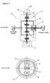
- a variable capacity oil pump that is capable of variably controlling the rotational speed of the oil pump with respect to the rotational speed of the engine by disposing a transmission mechanism 10 between a crankshaft of the engine and the oil pump is provided.
- the transmission mechanism includes a planetary gear mechanism 12, a hysteresis brake 14 and a one-way clutch 16.
- the planetary gear mechanism 12 includes a sun gear 18, a ring gear 20 and a plurality of planetary gears 22.
- the sun gear 18 is connected to the oil pump.
- the planetary gears are connected to the crankshaft through a carrier 24.
- the one-way clutch 16 is provided between the sun gear 18 and the carrier 24. The one-way clutch 16 acts so that the direction of a relative rotation of the sun gear 18 with respect to the carrier 24 is limited to the direction that the carrier 24 rotates, that is, the direction that the crankshaft rotates.
- the hysteresis brake 14 is connected to the outer side of the ring gear 20.
- the hysteresis brake 14 has a hysteresis material portion 28 on the frame of the ring gear so that the brake 14 rotates in accordance with the rotation of the ring gear 20.
- the hysteresis brake 14 further has an electromagnet 30 surrounding the hysteresis material portion 28.
- a braking force is generated by a magnetic field from the electromagnet 30.
- the rotational speed of the ring gear 20 can be adjusted by the brake 14 within a range from stop to a rotational speed equal to the rotational speed of the carrier 24 (that is, the rotational speed of the crankshaft).
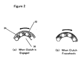
- Figure 2 shows an exemplary structure of the one-way clutch 16.
- an outer ring 34 which is connected to the carrier 24
- rollers 32 are received in engagement portions provided on the cam surface of the outer ring by the action of a spring.
- a shaft 36 (which is connected to the sun gear 18) is driven by the wedge action between the outer ring cam surface and the shaft 36.
- the rotational speed of the oil pump is controlled by combining the operations of the one-way clutch 16 and the hysteresis brake 14.
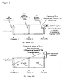
- Figure 3 shows a relationship among the rotational speed NR of the ring gear controlled by the hysteresis brake 14, the rotational speed NC of the carrier connected to the crankshaft, and the rotational speed NS of the sun gear connected to the oil pump.
- the transmission according to the invention can suppress a reduction in the fuel efficiency.
- the variable capacity pump can improve the fuel efficiency.
- the braking force may be generated by a motor.
- the electric power required for a brake driven by the motor is greater than required for the above hysteresis break. Therefore, generating the braking force by a motor may cancel the above described effect regarding the fuel efficiency achieved by the variable capacity oil pump. Further, if a brush motor is used, a failure may occur due to wear of the brush. If a brushless motor is used, a PDU (power distribution unit) is required, which may increase the weight of the pump system and decrease the fuel efficiency.
- Figure 4 shows operating characteristics of the variable capacity oil pump.
- Figure 4(a) shows characteristics of the oil pressure with respect to the engine rotational speed.
- Figure 4(b) shows characteristics of the rotational speed of the oil pump with respect to the engine rotational speed.
- Figure 4(c) shows the voltage applied to the hysteresis brake with respect to the engine rotational speed.
- a dashed line 31 of Figure 4(a) characteristics of the oil pressure when the planetary gear mechanism 12 rotates as one piece in accordance with the crankshaft (in other words, when the brake 14 is not actuated) is shown.
- the characteristics of the oil pressure as shown by the line 31 are established to meet the oil pressure required when the engine load is low.
- the voltage applied to the hysteresis brake in the condition where the engine rotational speed is low and the condition where the engine load is high (these conditions require a higher oil pressure), the voltage applied to the brake 14 is higher than required when the engine load is low.
- variable capacity oil pump having a transmission mechanism in accordance with one embodiment of the present invention can achieve the ideal characteristics of the oil pressure as shown in Figure 11.
- An oil pump control system using a variable capacity oil pump as described above will be described.
- a feedback control based on an actual value detected by a sensor provided in the oil pump and a desired value is typically performed.
- an oil pressure control or a pump rotational speed control is implemented.
- a desired value for the oil pressure corresponding to the engine rotational speed can be determined referring to the ideal oil pressure characteristics as shown in Figure 1 or Figure 4(a). By using this desired value, a feedback control for the oil pump can be performed.
- a conventional PID controller is used as a feedback controller, variations in the error between the desired value and the actual value for oil pressure may be large because the PID control has a tendency to cause the controlled value (the oil pressure) to overshoot.
- operating characteristics of the hysteresis brake change in accordance with the temperature. If the hysteresis brake is used continuously, the braking capability may decrease and the actual oil pressure may not precisely follow the desired value. Therefore, there is a need for a controller that quickly causes the error to converge without causing the actual oil pressure to overshoot the desired value.
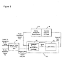
- an oil pressure feedback type of oil pump control system as shown in Figure 5 is configured.
- the oil pressure Poil that is detected by an oil pressure sensor 50 is controlled to converge to a desired oil pressure value Poil_cmd.
- a controller 46 comprises a 2-degree freedom sliding mode controller (hereinafter referred to a "2-degree freedom SMC") 42 and a delta-sigma ( ⁇ ) modulator 44.
- 2-degree freedom SMC the characteristics that the error converges and the characteristics that the error follows a desired value can be separately controlled. Since the 2-degree freedom SMC can specify the behavior of the error so that the error gradually approaches the desired value, overshooting of the error can be prevented.
- the sliding mode control is one type of the response assignment control.
- the delta-sigma modulation is capable of accurately controlling the output of the controlled object regardless of the response characteristics of the controlled object as long as the controlled object has a capability of reconstructing on/off inputs.
- the delta-sigma modulation can implement an accurate braking control regardless of variations in the response of the brake.
- a load parameter based on an intake air amount Gcyl of the engine, which is typically detected by an air flow meter of the engine, and the engine rotational speed Ne, which is typically detected by a sensor provided in the engine, are input into a desired value calculating unit 40.
- the desired oil pressure value Poil_cmd is determined based on these input values.
- This desired oil pressure value Poil_cmd and the oil pressure Poil detected by the oil pressure sensor 50 that is provided in the oil pump 48 are input into the 2-degree freedom SMC 42.
- the 2-degree freedom SMC 42 calculates a reference input Rop so that the oil pressure sensor output Poil converges to the desired oil pressure value Poil_cmd. Details of the calculation will be described.
- the 2-degree freedom SMC 42 performs a low-pass filtering upon the desired oil pressure value Poil cmd by using a desired value following response assignment parameter pole_f_op as shown in the equation (1).
- the waveform of the desired value which typically has a step, is smoothed.
- the waveform of the desired value is converted to a curve that gradually approaches the desired value.
- Poil_cmd_f m - pole_f_op ⁇ Poil_cmd_f ⁇ m - 1 + 1 + pole_f_op ⁇ Poil_cmd m
- Poil_cmd_f represents a desired value after the filtering process and "m" represents a control time.
- a control cycle of the 2 -degree freedom SMC is 50 milliseconds.
- the response assignment parameter is set to satisfy -1 ⁇ pole_f_op ⁇ 0.
- the trajectory of the desired value Poil_cmd_f after the filtering process is defined by the response assignment parameter pole_f_op.
- the speed that the control output Poil follows the desired value Poil_cmd can be specified depending on what form the trajectory for the desired value takes.
- the 2-degree freedom SMC42 calculates the reference input Rop so that the oil pressure sensor output Poil converges to the desired oil pressure value Poil_cmd_f thus set.
- E_op between the oil pressure sensor output Poil and the desired value Poil_cmd_f is determined as shown in the equation (2).
- E_op m Poil m - Poil_cmd_f m
- a switching function ⁇ is defined as shown in the equation (3).
- the switching function ⁇ defines a convergence behavior of the error.
- Pole_op is a disturbance suppressing response assignment parameter.
- the response assignment parameter Pole_op specifies the convergence speed of the error E_op when disturbance is applied.
- the response assignment parameter pole_op is set to satisfy - 1 ⁇ pole_op ⁇ 0.
- ⁇ _op m E_op m + pole_f ⁇ E_op ⁇ m - 1
- the reference input Rop is calculated as shown in the equation (4).
- Krch_op and Kadp_op are feedback gains.
- the first term in the right side of the equation (4) indicates a proportional term and the second term indicates an integral term.
- the equation (4) shows the calculation of the feedback amount according to the PI control where the switching function ⁇ is used as its input.
- the reference input Rop is input into the delta-sigma modulator 44.
- the delta-sigma modulator 44 receives the reference input Rop from the 2-degree freedom SMC as an input and applies a delta-sigma modulation algorithm to the reference input Rop to calculate a control input Uop. Details of the calculation will be described.
- the reference input Rop is limited by a limiting function lim_op within a range from a lower limit value Rop_min to an upper limit value Rop_max.
- the lower limit value Rop_min is set to 2 [v] and the upper limit value Rop_max is set to 8 [v].
- an offset value rop_oft which is to be used for calculating the control input Uop, is subtracted as shown in the equation (6).
- the offset value rop_oft is set to 5[v].
- "n" represents a control time. In this embodiment, a control cycle of the control by the delta-sigma modulator is 5 milliseconds.
- an error ⁇ _op(n) between the signal r2_op(n) obtained by the above offset process and the previous value Uop'(n-1) for the modulation signal is calculated.
- the error signal ⁇ _op(n) is added to the previous value ⁇ _op(n-1) for the integral of the error to determine the current value ⁇ _op(n) for the integral of the error.
- ⁇ _op n r ⁇ 2 _op n - Uop ⁇ ⁇ n - 1
- ⁇ _op n ⁇ _op ⁇ n - 1 + ⁇ _op n
- a binary non-linear function Fnl_op is applied to the integral of the error ⁇ _op(n) so that the integral of the error is converted to a binary value.
- the binary non-linear function Fnl_op outputs the modulation signal Uop'(n) having a value of +R.
- the binary non-linear function Fnl_op outputs the modulation signal having a value of -R.
- R is a predetermined value that is larger than the maximum absolute value of r2_op.
- the integral ⁇ _op(n) is zero, a value of zero may be output as the modulation signal.
- the offset process is applied to the modulation signal Uop'(n) to determine the control input Uop(n).
- the control input thus generated through the delta-sigma modulation has a value of either 5+R [v] or 5-R [v].
- Uop ⁇ n Fnl_op ⁇ _op n
- Uop n Uop ⁇ n + rop_oft
- the above-described controller comprises a modulator that uses the delta-sigma modulation algorithm.
- the modulator may be configured to use a sigma-delta ( ⁇ ) modulation algorithm or a delta ( ⁇ ) modulation algorithm.
- ⁇ represents the integral
- ⁇ represents the subtraction.
- Equations performed in the sigma-delta modulator are shown in the equations (11) through (17).
- r ⁇ 1 _op n lim_op Rop m
- Uop ⁇ n Fnl_op ⁇ ru_op n
- Uop n Uop ⁇ n + rop_oft
- Equations performed in the delta modulator are shown in the equations (18) through (23).
- r ⁇ 1 _op n lim_op Rop m
- Uop ⁇ n Fnl_op ⁇ ru_op n
- Uop n Uop ⁇ n + rop_oft
- a feedback control of the variable capacity oil pump is implemented by using a pump rotational speed sensor.
- a desired pump rotational speed corresponding to the engine rotational speed can be established from the pump rotational speed characteristics as shown in Figure 4(b).
- Figure 6 shows a structure of a pump rotational speed feedback type of oil pump control system.
- a pump rotational speed Nop detected by a pump rotational speed sensor 52 is controlled to converge to a desired rotational speed Nop_cmd corresponding to the engine rotational speed and the load condition of the engine.
- the controller comprises a 2-degree freedom SMC and a delta-sigma ( ⁇ ) modulator in a similar way to those of the oil pressure feedback type of oil pump control system as described above.
- control method of this embodiment will be described. Since the control method is similar to the control method in the above-described oil pressure feedback type of oil pump control system, only differences will be described.
- the desired value calculating unit 40 determines a desired pump rotational speed value Nop_cmd based on the engine load parameter (typically, intake air amount Gcyl) and the engine rotational speed.
- the desired rotational speed value Nop_cmd and the pump rotational speed Nop detected by the pump rotational speed sensor 52 that is provided in the oil pump 48 are input into the 2-degree freedom SMC 42.
- the 2-degree freedom SMC 42 calculates a reference input Rop that is to be used for causing the pump rotational speed sensor output Nop to converge to the desired pump rotational speed value Nop_cmd. Equations performed in the calculation will be shown. Since the calculation is similar to the equations (1) through (4), details regarding the calculation will not be described. Variables and functions used in the equations are similar to those used in the equations (1) through (4). As to the same variables and functions as those in the equations (1) through (4), a quotation mark (') is added.
- the reference input Rop' is input into the delta-sigma modulator 44.
- the delta-sigma modulator 44 receives the reference input Rop' from the 2-degree freedom SMC as an input to calculate a control input Uop by applying the delta-sigma modulation algorithm to the reference input. Since the calculation for determining the reference input is similar to the equations (5) through (10), details regarding the calculation will not be described.
- the system according to this embodiment comprises a modulator that uses the delta-sigma modulation algorithm.
- the modulator may be configured to use the sigma-delta ( ⁇ ) modulation algorithm as shown in the equation (11) through (17), or the delta ( ⁇ ) modulation algorithm as shown in the equations (18) through (23).
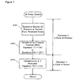
- FIG. 7 shows a control flow for the above-described oil pump control system.
- the control flow has two operation stages.
- step S100 the desired oil pressure value or the desired pump rotational speed value is determined based on the engine rotational speed and the load parameter.
- step S102 the calculation of the 2-degree freedom sliding mode control is performed to calculate the reference input. The calculation is shown in the equations (1) through (4) or in the equations (24) through (27).
- the operation of step S100 and step S102 is carried out every 50 milliseconds in one embodiment of the present invention.
- the delta-sigma modulation algorithm is performed to calculate the control input in step S104.
- the operation of step S104 is carried out every 5 milliseconds.
- the transmission mechanism 10 for the variable capacity oil pump as shown in Figure 1 can be used for implementing a variable capacity water pump 56 by replacing the oil pump connected to the sun gear 18 with the water pump.
- a control system for the water pump is similar to the control system for the oil pump.
- a water temperature control or a pump rotational speed control is implemented.
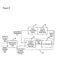
- FIG 8 shows a water temperature feedback type of water pump control system.
- a controller 46 includes a 2-degree freedom sliding mode controller 42 and a delta-sigma ( ⁇ ) modulator 44 in a similar way to the oil pump system as described above.
- a water temperature sensor 54 is provided in the water pump.
- a cooling water temperature Tw that is an output of the sensor 54 and a desired water temperature value Tw_cmd that is determined by the desired value calculating unit 40 are input into the controller 46.
- Details of the equations performed by the 2-degree freedom sliding mode controller for calculating the reference input Rwp are omitted because they are represented in a similar way to the equations (1) through (4) except that symbols used in the equations are different.
- details of the equations performed by the delta-sigma modulator for calculating the control input Uwp from the reference input Rwp are omitted because they are similar to the equations (5) through (10).
- Figure 9 shows a pump rotational speed feedback type of water pump control system.
- a pump rotational sensor 52 is provided in the water pump.
- a water pump rotational speed Nwp that is an output of the sensor 52 and a desired rotational speed value Nwp_cmd that is determined by the desired value calculating unit 40 are input into the controller 46. Calculation by the controller is performed in a similar way to the water temperature feedback type of water pump control system.
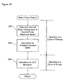
- FIG 10 is a control flow for the above-described water pump control system.
- the control flow has two operation stages.
- step S200 the desired water temperature value or the desired pump rotational speed value is determined based on the engine rotational speed and the load parameter.
- step S202 the calculation of the 2-degree freedom sliding mode control is performed to calculate the reference input. The calculation is performed as shown in the equations (1) through (4) or in the equations (24) through (27).
- the operation of step S200 and step S202 is carried out every 50 milliseconds in one embodiment of the present invention.
- the delta-sigma modulation algorithm is performed to calculate the control input in step S204.
- the operation of step S204 is carried out every 5 milliseconds.
Landscapes
- Engineering & Computer Science (AREA)
- Mechanical Engineering (AREA)
- General Engineering & Computer Science (AREA)
- Chemical & Material Sciences (AREA)
- Combustion & Propulsion (AREA)
- Control Of Positive-Displacement Pumps (AREA)
- Rotary Pumps (AREA)
- Details And Applications Of Rotary Liquid Pumps (AREA)
- Control Of Transmission Device (AREA)
Applications Claiming Priority (2)
| Application Number | Priority Date | Filing Date | Title |
|---|---|---|---|
| JP2004016615A JP2005207357A (ja) | 2004-01-26 | 2004-01-26 | エンジンの可変容量流体ポンプ |
| JP2004016615 | 2004-01-26 |
Publications (3)
| Publication Number | Publication Date |
|---|---|
| EP1557543A2 EP1557543A2 (en) | 2005-07-27 |
| EP1557543A3 EP1557543A3 (en) | 2005-08-24 |
| EP1557543B1 true EP1557543B1 (en) | 2007-03-07 |
Family
ID=34631968
Family Applications (1)
| Application Number | Title | Priority Date | Filing Date |
|---|---|---|---|
| EP05000933A Expired - Fee Related EP1557543B1 (en) | 2004-01-26 | 2005-01-18 | A variable capacity fluid pump for an engine |
Country Status (4)
| Country | Link |
|---|---|
| US (1) | US7503753B2 (ja) |
| EP (1) | EP1557543B1 (ja) |
| JP (1) | JP2005207357A (ja) |
| DE (1) | DE602005000638T2 (ja) |
Families Citing this family (28)
| Publication number | Priority date | Publication date | Assignee | Title |
|---|---|---|---|---|
| GB2431217A (en) * | 2005-10-11 | 2007-04-18 | Ford Global Tech Llc | Piston oil spray cooling system with two nozzles |
| KR100873859B1 (ko) * | 2006-12-14 | 2008-12-15 | 현대자동차주식회사 | 차량용 오일 펌프 |
| US8801393B2 (en) * | 2007-10-12 | 2014-08-12 | Pierce Manufacturing Inc. | Pressure control system and method |
| WO2009146448A2 (en) * | 2008-05-30 | 2009-12-03 | Metaldyne Company Llc | Variable output fluid pump system |
| JP4649520B2 (ja) | 2009-04-10 | 2011-03-09 | 本田技研工業株式会社 | ギヤポンプ |
| DE102010001259B4 (de) * | 2009-07-30 | 2013-01-31 | Zf Friedrichshafen Ag | Getriebeölpumpe für ein Automatgetriebe |
| KR101063496B1 (ko) | 2009-08-28 | 2011-09-07 | 기아자동차주식회사 | 클러치 워터펌프와 그것의 제어장치 및 방법 |
| GB2478716B (en) * | 2010-03-15 | 2016-07-13 | Gm Global Tech Operations Llc | Coolant pump for internal combustion engines |
| CN101907098B (zh) * | 2010-08-17 | 2012-01-04 | 胡大伦 | 低水头聚能抽水机 |
| GB2486195A (en) * | 2010-12-06 | 2012-06-13 | Gm Global Tech Operations Inc | Method of Operating an I.C. Engine Variable Displacement Oil Pump by Measurement of Metal Temperature |
| DE102011015102A1 (de) | 2011-03-25 | 2012-09-27 | Audi Ag | Getriebeanordnung für ein Nebenaggregat einer Brennkraftmaschine |
| DE102011115065B3 (de) * | 2011-10-07 | 2012-10-04 | Audi Ag | Kühlmittelfördereinrichtung sowie Verfahren zum Betreiben einer Kühlmittelfördereinrichtung |
| DE102012200279A1 (de) * | 2012-01-11 | 2013-07-11 | Ford Global Technologies, Llc | Verfahren und Vorrichtung zum Betreiben eines Schmiersystems einesVerbrennungsmotors |
| CN103883864A (zh) * | 2012-04-20 | 2014-06-25 | 吴小平 | 行星奇异齿齿轮泵液压马达及奇异齿变容技术 |
| DE102013000894A1 (de) * | 2013-01-18 | 2014-07-24 | Volkswagen Aktiengesellschaft | Verfahren und Vorrichtung zur Regelung eines Öldrucks eines Motors für ein Fahrzeug |
| CN105143672B (zh) | 2013-04-12 | 2017-03-08 | 本田技研工业株式会社 | 车辆的油吸入装置 |
| DE102013109412A1 (de) * | 2013-08-29 | 2015-03-05 | Prominent Gmbh | Verfahren zur Verbesserung von Dosierprofilen von Verdrängerpumpen |
| WO2015035006A2 (en) * | 2013-09-05 | 2015-03-12 | Eaton Corporation | Variable output centrifugal pump |
| DE102014002868A1 (de) * | 2014-02-24 | 2015-08-27 | GM Global Technology Operations LLC (n. d. Ges. d. Staates Delaware) | Ölpumpenanordnung für einen Druckschmierölkreislauf |
| JP6445804B2 (ja) * | 2014-07-23 | 2018-12-26 | 株式会社Subaru | オイルポンプ装置 |
| DE102015005344A1 (de) * | 2015-04-28 | 2016-11-03 | Volkswagen Aktiengesellschaft | Nebenaggregatsantriebsvorrichtung |
| DE102016203549B4 (de) * | 2016-03-03 | 2021-08-12 | Audi Ag | Verfahren zum Ermitteln eines Verhaltens eines in einem Fahrzeug verbauten Ventils, sowie ein Fahrzeug |
| CN110529217B (zh) * | 2018-05-25 | 2021-07-20 | 宝沃汽车(中国)有限公司 | 机油泵驱动装置、发动机以及车辆 |
| DE102018214661B4 (de) | 2018-08-29 | 2023-11-02 | Ford Global Technologies, Llc | Flüssigkeitspumpe und Kraftfahrzeug mit einer Flüssigkeitspumpe |
| WO2021137854A1 (en) * | 2019-12-31 | 2021-07-08 | Halliburton Energy Services, Inc. | Predict brake horsepower for a pump for viscous applications |
| JP2024517799A (ja) * | 2021-05-04 | 2024-04-23 | カミンズ インコーポレーテッド | エンジン潤滑システム、潤滑流体循環システム、及び流圧を調整するための方法 |
| CN114412607B (zh) * | 2021-12-14 | 2023-10-20 | 东风汽车集团股份有限公司 | 一种发动机的润滑系统 |
| CN115234339A (zh) * | 2022-08-22 | 2022-10-25 | 潍柴动力股份有限公司 | 发动机的机油泵组件、发动机和发动机的机油泵转速控制方法 |
Family Cites Families (16)
| Publication number | Priority date | Publication date | Assignee | Title |
|---|---|---|---|---|
| DE1653599A1 (de) * | 1967-06-03 | 1970-11-12 | Rheinstahl Huettenwerke Ag | Antrieb fuer Pumpen zum Erzeugen von Presswasser fuer die Entzunderung,z.B. in Walzwerken |
| US3944253A (en) * | 1974-05-07 | 1976-03-16 | Ripley Iii George | Infinitely variable transmission for pedal-driven vehicles |
| DE2757300C2 (de) * | 1977-12-22 | 1982-08-12 | Zahnradfabrik Friedrichshafen Ag, 7990 Friedrichshafen | Leistungsverzweigtes hydrostatisch-mechanisches Verbundgetriebe |
| JPS5814583B2 (ja) * | 1978-05-19 | 1983-03-19 | トヨタ自動車株式会社 | 自動車用駆動装置 |
| DE3440428A1 (de) * | 1983-11-17 | 1985-05-30 | Zahnradfabrik Friedrichshafen Ag, 7990 Friedrichshafen | Temperaturgesteuerter luefterantrieb fuer maschinen grosser leistung |
| DE3622335C2 (de) * | 1985-07-31 | 1995-11-23 | Volkswagen Ag | Antriebseinrichtung für Nebenaggregate einer Brennkraftmaschine |
| DE4041158C1 (ja) * | 1990-12-21 | 1992-08-20 | Mercedes-Benz Aktiengesellschaft, 7000 Stuttgart, De | |
| DE4128543A1 (de) * | 1991-08-28 | 1993-03-18 | Daimler Benz Ag | Antriebsvorrichtung fuer mindestens ein nebenaggregat einer kraftmaschine |
| US5512022A (en) * | 1993-10-26 | 1996-04-30 | Suzuki; Naruhito | Motor mechanism |
| US5512021A (en) * | 1994-02-10 | 1996-04-30 | Shash; Joseph L. | Variable ratio transmission |
| US5575735A (en) | 1995-04-06 | 1996-11-19 | Caterpillar Inc. | Integrated power transmitting system |
| US5860884A (en) * | 1996-10-28 | 1999-01-19 | Tecumseh Products Company | Variable speed transmission and transaxle |
| JP3904923B2 (ja) | 2001-12-28 | 2007-04-11 | 本田技研工業株式会社 | 制御装置 |
| JP4145520B2 (ja) | 2001-11-19 | 2008-09-03 | 本田技研工業株式会社 | 内燃機関のカム位相制御装置 |
| US20030119620A1 (en) * | 2001-12-21 | 2003-06-26 | Caterpillar Inc. | Variable and differential output drive system |
| DE10318711A1 (de) * | 2003-04-25 | 2004-11-25 | Volkswagen Ag | Vorrichtung zum Antrieb der Kühlmittelpumpe einer Brennkraftmaschine |
-
2004
- 2004-01-26 JP JP2004016615A patent/JP2005207357A/ja active Pending
-
2005
- 2005-01-11 US US11/032,083 patent/US7503753B2/en not_active Expired - Fee Related
- 2005-01-18 EP EP05000933A patent/EP1557543B1/en not_active Expired - Fee Related
- 2005-01-18 DE DE602005000638T patent/DE602005000638T2/de active Active
Also Published As
| Publication number | Publication date |
|---|---|
| DE602005000638T2 (de) | 2007-11-15 |
| EP1557543A2 (en) | 2005-07-27 |
| JP2005207357A (ja) | 2005-08-04 |
| EP1557543A3 (en) | 2005-08-24 |
| DE602005000638D1 (de) | 2007-04-19 |
| US20050175484A1 (en) | 2005-08-11 |
| US7503753B2 (en) | 2009-03-17 |
Similar Documents
| Publication | Publication Date | Title |
|---|---|---|
| EP1557543B1 (en) | A variable capacity fluid pump for an engine | |
| US6219608B1 (en) | Electronic transmission control system for automotive vehicle with continuously variable automatic transmission | |
| US6243638B1 (en) | Electronic transmission control system for automotive vehicle with continuously variable automatic transmission | |
| US7322903B2 (en) | Control method for cooling a launch clutch and an electric motor in a hybrid electric vehicle powertrain | |
| US8287409B2 (en) | Hydraulic control system and method of continuously variable transmission | |
| US6314727B1 (en) | Method and apparatus for controlling an electro-hydraulic fluid system | |
| JP2007326556A (ja) | パラレルハイブリッド駆動経路の作動方法 | |
| US5996343A (en) | Overspeed control system for a hydro-mechanical drive system | |
| US8360907B2 (en) | Hydraulic control system of continuously variable transmission | |
| JP2018516345A (ja) | 無段変速機のための制御システム | |
| CN113007055A (zh) | 用于运行转速可变的调节泵的方法 | |
| JP2012523337A (ja) | 流体機械による作動媒体サイクルにおける圧力ピークを抑止するための方法 | |
| JP4164057B2 (ja) | ベルト式無段変速機 | |
| US6343250B1 (en) | Method and apparatus for smoothing the output of a hydrostatic transmission near zero speed | |
| WO2017204350A1 (ja) | 車両の制動制御装置 | |
| CN108426030B (zh) | 静液压传动装置和用于以其进行制动的方法 | |
| US20220120297A1 (en) | Method for Operating a Hydraulic Drive | |
| WO2003019302A2 (en) | Hybrid control system | |
| JP2011052796A (ja) | ベルト式無段変速機の油圧制御装置 | |
| JPH03213763A (ja) | 無段変速機の制御装置 | |
| JP4146840B2 (ja) | 自動変速制御装置 | |
| JP6707981B2 (ja) | 車両の制動制御装置 | |
| EP3913257B1 (en) | System and method for monitoring the wear state of a hydrostatic transmission | |
| US10822772B1 (en) | Hydraulic systems with variable speed drives | |
| CN115667714A (zh) | 用于适配行驶驱动装置的液压泵的压力的方法 |
Legal Events
| Date | Code | Title | Description |
|---|---|---|---|
| PUAI | Public reference made under article 153(3) epc to a published international application that has entered the european phase |
Free format text: ORIGINAL CODE: 0009012 |
|
| PUAL | Search report despatched |
Free format text: ORIGINAL CODE: 0009013 |
|
| AK | Designated contracting states |
Kind code of ref document: A2 Designated state(s): AT BE BG CH CY CZ DE DK EE ES FI FR GB GR HU IE IS IT LI LT LU MC NL PL PT RO SE SI SK TR |
|
| AX | Request for extension of the european patent |
Extension state: AL BA HR LV MK YU |
|
| AK | Designated contracting states |
Kind code of ref document: A3 Designated state(s): AT BE BG CH CY CZ DE DK EE ES FI FR GB GR HU IE IS IT LI LT LU MC NL PL PT RO SE SI SK TR |
|
| AX | Request for extension of the european patent |
Extension state: AL BA HR LV MK YU |
|
| RIC1 | Information provided on ipc code assigned before grant |
Ipc: 7F 01P 5/12 B Ipc: 7F 01M 1/16 B Ipc: 7F 04D 13/02 A Ipc: 7F 01P 7/14 B |
|
| 17P | Request for examination filed |
Effective date: 20051209 |
|
| AKX | Designation fees paid |
Designated state(s): DE GB |
|
| GRAP | Despatch of communication of intention to grant a patent |
Free format text: ORIGINAL CODE: EPIDOSNIGR1 |
|
| GRAS | Grant fee paid |
Free format text: ORIGINAL CODE: EPIDOSNIGR3 |
|
| GRAA | (expected) grant |
Free format text: ORIGINAL CODE: 0009210 |
|
| AK | Designated contracting states |
Kind code of ref document: B1 Designated state(s): DE GB |
|
| REG | Reference to a national code |
Ref country code: GB Ref legal event code: FG4D |
|
| REF | Corresponds to: |
Ref document number: 602005000638 Country of ref document: DE Date of ref document: 20070419 Kind code of ref document: P |
|
| PLBE | No opposition filed within time limit |
Free format text: ORIGINAL CODE: 0009261 |
|
| STAA | Information on the status of an ep patent application or granted ep patent |
Free format text: STATUS: NO OPPOSITION FILED WITHIN TIME LIMIT |
|
| 26N | No opposition filed |
Effective date: 20071210 |
|
| PGFP | Annual fee paid to national office [announced via postgrant information from national office to epo] |
Ref country code: DE Payment date: 20100114 Year of fee payment: 6 Ref country code: GB Payment date: 20100113 Year of fee payment: 6 |
|
| GBPC | Gb: european patent ceased through non-payment of renewal fee |
Effective date: 20110118 |
|
| PG25 | Lapsed in a contracting state [announced via postgrant information from national office to epo] |
Ref country code: GB Free format text: LAPSE BECAUSE OF NON-PAYMENT OF DUE FEES Effective date: 20110118 |
|
| REG | Reference to a national code |
Ref country code: DE Ref legal event code: R119 Ref document number: 602005000638 Country of ref document: DE Effective date: 20110802 |
|
| PG25 | Lapsed in a contracting state [announced via postgrant information from national office to epo] |
Ref country code: DE Free format text: LAPSE BECAUSE OF NON-PAYMENT OF DUE FEES Effective date: 20110802 |