EP1557222A2 - Pipettiervorrichtung mit einer Abwurfeinrichtung für Pipettenspitzen - Google Patents
Pipettiervorrichtung mit einer Abwurfeinrichtung für Pipettenspitzen Download PDFInfo
- Publication number
- EP1557222A2 EP1557222A2 EP05000212A EP05000212A EP1557222A2 EP 1557222 A2 EP1557222 A2 EP 1557222A2 EP 05000212 A EP05000212 A EP 05000212A EP 05000212 A EP05000212 A EP 05000212A EP 1557222 A2 EP1557222 A2 EP 1557222A2
- Authority
- EP
- European Patent Office
- Prior art keywords
- spring
- pipetting device
- drive
- ejector
- pipetting
- Prior art date
- Legal status (The legal status is an assumption and is not a legal conclusion. Google has not performed a legal analysis and makes no representation as to the accuracy of the status listed.)
- Granted
Links
Images


Classifications
-
- B—PERFORMING OPERATIONS; TRANSPORTING
- B01—PHYSICAL OR CHEMICAL PROCESSES OR APPARATUS IN GENERAL
- B01L—CHEMICAL OR PHYSICAL LABORATORY APPARATUS FOR GENERAL USE
- B01L3/00—Containers or dishes for laboratory use, e.g. laboratory glassware; Droppers
- B01L3/02—Burettes; Pipettes
- B01L3/0275—Interchangeable or disposable dispensing tips
- B01L3/0279—Interchangeable or disposable dispensing tips co-operating with positive ejection means
-
- B—PERFORMING OPERATIONS; TRANSPORTING
- B01—PHYSICAL OR CHEMICAL PROCESSES OR APPARATUS IN GENERAL
- B01L—CHEMICAL OR PHYSICAL LABORATORY APPARATUS FOR GENERAL USE
- B01L2200/00—Solutions for specific problems relating to chemical or physical laboratory apparatus
- B01L2200/06—Fluid handling related problems
- B01L2200/0689—Sealing
-
- B—PERFORMING OPERATIONS; TRANSPORTING
- B01—PHYSICAL OR CHEMICAL PROCESSES OR APPARATUS IN GENERAL
- B01L—CHEMICAL OR PHYSICAL LABORATORY APPARATUS FOR GENERAL USE
- B01L2200/00—Solutions for specific problems relating to chemical or physical laboratory apparatus
- B01L2200/08—Ergonomic or safety aspects of handling devices
- B01L2200/087—Ergonomic aspects
-
- B—PERFORMING OPERATIONS; TRANSPORTING
- B01—PHYSICAL OR CHEMICAL PROCESSES OR APPARATUS IN GENERAL
- B01L—CHEMICAL OR PHYSICAL LABORATORY APPARATUS FOR GENERAL USE
- B01L2300/00—Additional constructional details
- B01L2300/02—Identification, exchange or storage of information
- B01L2300/025—Displaying results or values with integrated means
- B01L2300/026—Drum counters
Definitions
- the invention relates to a pipetting device with at least one approach for attaching a pipette tip and a discharge device for releasing a Pipette tip from the neck.
- Pipetting devices are used especially in the laboratory for dosing liquids used. These are taken up in pipette tips through a tip opening and spent.
- air cushion pipettes is a displacement device for a gas integrated into the pipetting device and communicating through the approach with the Pipette tip connected.
- the displacement device is an air cushion displaced so that liquid sucked into the pipette tip and ejected from it becomes.
- the displacement device is usually a cylinder with a movable therein Piston.
- Pipette tips are detachably connected to the neck to keep them in after use can be replaced with a fresh pipette tip. This can be at subsequent dosing contaminations are avoided.
- Pipette tips for the one-time use are available inexpensively from plastic.
- the approach for attaching pipette tips is often a cylindrical or conical projection with respect to a base body or a housing, on the one Pipette tip can be clamped with a matching push-on opening or receptacle is. This can be done without touching the pipette tip by pressing the projection into the Plug-in opening happen to be provided in a holder pipette tip.
- a discharge device with a drive device and an ejector.
- the ejector By Actuating the drive means, the ejector is displaced so that it the pipette tip from the approach solves, without this must be handled by the user.
- the drive device has a mechanism that by means of an actuating button must be manually operated to release the pipette tip from the approach.
- drive devices with an electric motor drive. The Loosening the pipette tip from the neck can require considerable effort especially with pipette tips clamped firmly on the neck.
- single-channel systems i.e.
- Pipetting devices that provide a single approach to a single Pipette tip, this may be the ejection of the pipette tip from the approach make it difficult or impossible.
- Particularly high expenditure of force can be achieved in multi-channel pipetting systems, the multiple parallel approaches for attaching pipette tips have to be required due to multiple peak ejection forces.
- EP 0 992 288 A2 is a pipetting system with an axially movable Ejector for releasing a pipette tip from a hub, drive means for driving the axial movements of the ejector and an axial drive movement the drive device transmit in an axial movement of the ejector Anlagenstoff-, pressure medium or linkage known. From the ejector to the Force applied by the pipette tip exceeds the force applied by the user, whereby the throwing off is facilitated.
- a pipetting device which is an approach to Attaching a pipette tip having a protruding from a shaft Section of a shaft which is rotatable in the shaft.
- the pipetting device has a rotary drive for the shaft.
- the end facing the approach is the Shank designed as a curved surface.
- the pipette tip points at the insertion end also a curve surface.
- the invention is based on the object, a pipetting device to provide that the force required for the operation of the discharge device reduced.
- a pipette tip by axial Insertion of the approach plugged into the plug-in opening This is the Aufsteckkraft initiated into the spring. If the attachment force exceeds a certain value, the spring is elastically deformed until the pipette tip clamped onto the neck bumps against the stop. As soon as the pipette tip touches the stop, you can they will not be deferred on the approach anymore. As a result, the Tarsteckkraft limited the pipette tip.
- the Aufsteckkraft is through the spring characteristic the spring or any existing bias of the spring determined.
- the feather is designed and optionally biased so that the pipette tip is exactly when sitting with the desired attachment force on the neck, at the stop is applied.
- the Aufsteckkraft is set so that the pipette tip safely on the Approach sits or seals. Since a precise defined Aufsteckkraft is achieved, it is possible to limit the Aufsteckkraft to a low value at which the required Safety of the seat and the seal is just given. Thus, the Aufsteckkraft compared to conventional pipetting significantly reduced in which, due to the uncertainties of putting on a regular excessive Aufsteckkraft is expended. Accordingly, in the inventive Pipetting the effort required for the operation of the ejection device reduced. In manually operable ejection devices are by Reduction of operating forces the tendon and muscle strain of the user reduced. Electromotive operated ejection devices come with motors lower power.
- the spring is designed and / or biased that the approach of a defined Aufsteckkraft by Attaching a pipette tip can be applied to the approach, in such a way to Stop is displaced that the pipette tip abuts the stop.
- the neck and ejector are relative axially and / or rotationally movable.
- the invention relates to a, in where the ejector is stationary with respect to the pipetting and the Drive device exclusively moves the approach. Furthermore, the invention relates Implementations in which the drive means the ejector and the approach emotional. In preferred embodiments, the approach is with respect to the pipetting device stationary and the drive device is only operatively connected to the ejector, so that only the ejector is movable by means of the drive means.
- the approach is supported directly on the spring.
- the Connection of the approach with a permanently connected to the main body displacement device can be done by means of a flexible connection, e.g. with help of a flexible hose or a telescopic pipe connection.
- the approach is fixed with a displacement device - e.g. with a Cylinder of a relative to the body axially displaceable piston-cylinder device - connected.
- the displacement device is then with the approach relocated.
- the displacement of the displacement device can be controlled by the drive device be compensated for the displacement device.
- the cylinder is supported by the spring on the body, so that the Approach indirectly cushioned over the cylinder.
- the spring is extended in the axial direction of the neck Coil spring.
- the coil spring is preferably coaxial with the extension.
- the displacement device or drive device for the displacement device can be advantageously passed through the coil spring.
- the pipetting device can be executed with a non-preloaded spring. Then it will be the spring corresponding to the increase in Aufsteckkraft when attaching the approach compressed to the pipette tip.
- the spring has a spring bias. As a result, it comes only to an axial displacement of the approach when the Aufsteckkraft exceeds the force to bias the spring. This will be the for defined the reaching of the stop required Aufsteckkraft. It also favors This particularly compact spring arrangements and short displacement paths of the Approach.
- the stop on which the pipette tip when plugging meets firmly connected to the body.
- the stop is axially movable with respect to the approach and a fixed to the Body connected limit for the axial movement of the stop to Base body available.
- the stop is formed on the ejector.
- the stop At a Execution of the ejector as the approach coaxial sleeve is the stop by the formed the approach facing the end of the sleeve.
- the approach is different ways in its initial axial position for recording a pipette tip fixed, for example by connecting the approach with the spring.
- the starting position of the approach is then through the starting position defines the spring unloaded by the approach.
- the Approach in the direction of the spring away supported on another stop, against which he is pressed by the spring.
- the starting position is precisely determined.
- no connection between approach and spring is required.
- the spring is exchangeable and / or is a device for adjusting the spring preload available. This is an adaptation of Push-on and ejection forces on differently shaped or sized pipette tips possible. The range of application of the pipetting device is thereby increased.
- the drive device is against the action of a on the one hand on a movable part of the drive means and on the other hand on Main body supported further spring operable.
- the drive device returns after actuation automatically back to their original position.
- a defined Starting position is e.g. with respect to the body fixed limit for the Movement of the ejector or the drive device available. This can at the same time the limit for the axial movement of the stop to the body out be.
- the base body on a support or frame.
- the main body has a housing, optionally with a carrier or frame contained therein.
- the pipetting device is a hand-held device and / or a stationary device and / or an electrically powered device and / or a (Semi) automatic.
- the pipetting device of Hand led to the location of the sample taking and sample deliveries and becomes the Pickup and delivery of liquid and the operation of the discharge device controlled by hand.
- the drive means for the displacement device and / or the ejector are designed mechanically and / or electromechanically. The latter also applies to the execution of the pipetting as a stationary device.
- the pipetting device When the pipetting device is designed as a (semi) automaton, all Functions or part of the functions of the pipetting devices (recording and Dispensing liquid, moving the pipetting devices into positions for Picking up and dispensing liquid or pipette tips, picking up and dispensing from pipette tips) automatically.
- the pipetting device has a number of parallel Approaches for receiving pipette tips. This is a Multichannel pipetting. Due to the multiplied peak ejection forces Here, the use of the invention particularly advantageous.
- the approaches associated with a common ejector are associated with the approaches associated with a common ejector.
- the displacement device and the drive device for driving the displaceable limitation of the pipetting device are easily achieved by Mating along a longitudinal axis of the bayonet connection and turning around the longitudinal axis of the bayonet connection connected to each other or in reverse Way separable from each other.
- the bayonet connection will be simultaneously the operative connection between the drive member and the displaceable boundary is established, without the need for special further actions.
- the active compound is solved without special further actions.
- the invention enables a particularly simple, fast and secure connection and separating the displacing means and the driving means for driving the movable limit, for example, during assembly, before autoclaving or other cleaning of the lower part, before replacing the lower part to For the purpose of changing the work area, repair, etc.
- the Bayonet connection is particularly susceptible to interference.
- the drive device for driving the displaceable boundary can be configured in different ways. It has technical means, that To move drive member so that this is the movable limit of Displaced displacement device.
- the drive member carries e.g. a Linear motion off.
- the drive means for driving the movable boundary on a linear drive are e.g. around a directly operable by pressing a button manually stroke rod or one over an electric drive motor and a transmission linearly displaceable lifting rod.
- a pneumatically or hydraulically operated Pressure medium cylinder as a drive for the lifting rod, via a pneumatic or hydraulic control and a pressure medium reservoir is actuated. If that Drive organ performs no linear movement, but a spatial Feed motion, the drive means for driving the displaceable Limiting a corresponding drive.
- the drive means for driving the displaceable boundary a housing in which drive and drive member are arranged.
- the drive member is a parallel to the longitudinal axis of the Bayonet connection displaceable lifting rod of the drive device and has the Displacement device connected to the boundary, transverse to the lifting rod directed contact surface, by a lifting spring against the end of the lifting rod is pressed.
- the operative connection between the drive member and movable limit automatically when making the bayonet connection made and automatically released when dissolving the bayonet connection.
- the contact surface is connected to a via a rod with the displaceable boundary connected pressure piece formed and is the lifting spring designed as a helical spring, which at one end on the pressure piece and the other at the Displacement chamber is supported.
- the bayonet connection can be configured in various ways. Involved by The invention is in particular the embodiment of the drive device as a male Part and the displacement device as a female part of the bayonet connection and vice versa.
- the drive device a cylindrical receptacle having at one end an opening through which the cylindrical receptacle in the axial direction is accessible from the outside, the at least having an axially directed longitudinal groove, with a circumferential direction of the cylindrical Receiving directional annular groove is connected, and has the displacement device on a cylindrical portion at least one outwardly projecting Projection, wherein the cylindrical portion in the axial direction of the cylindrical Recording through the opening in the receptacle and with the projection in the Longitudinal groove can be inserted and screwed with the projection in the annular groove.
- the drive means the female and the displacement device the male part.
- the annular groove at a distance from the longitudinal groove a in the axial direction of the recording extended boundary wall, up to the Projection is rotatable. The achievement of the limit indicates to the user that the Bayonet connection is made.
- the annular groove is at a distance from the longitudinal groove a parallel thereto extending L Lucassnutabexcellent connected in a Distance from the opening ends.
- the annular groove has a ramp-like boundary wall, their distance from the opening with increasing distance from the Longitudinal groove increases.
- the ramp-like course of the boundary wall facilitates the Finding the connection position and separating the displacement of the drive device.
- the longitudinal groove, the annular groove and optionally the L jossnutabrough formed in a cylindrical coupling piece, which is the receptacle of Drive device forms and is fixed in this. This will produce, Assembly and disassembly easier.
- the drive device on a spring which against the Displacement device connected to the drive device via the bayonet connection suppressed. This will secure the bayonet connection.
- the spring is at a further opening of the receptacle arranged, that of the opening for axial insertion of the displacement device opposite. Through the opening displacement and spring act on each other one.
- the spring is a helical spring which is supported on an inner end face of the coupling piece.
- the longitudinal groove and / or annular groove and / or the Leksnutabrough opened for further opening.
- the displacement device is a piston-cylinder device with a cylinder and a piston displaceable therein and has the Piston on the movable limit.
- Other displacement devices are also included by the invention, for example, a displacement chamber with an elastic wall forming the displaceable boundary.
- a piston-cylinder device is e.g. operated by a linear drive device.
- a corresponding actuation is in a displacement chamber with an elastic Wall possible.
- the latter can also be a drive device with a controlled spatial drive movement. So it is possible, for example, the elastic wall by action of a hydraulic or pneumatic Control pressure medium outside.
- the approach is coaxial with the longitudinal axis of the bayonet connection aligned. According to a further embodiment, the approach is fixed with connected to the displacement device.
- the pipetting device has a discharge device for Discard a pipette tip from the hub, the one at the drive device arranged discharge drive, one arranged on the displacement device Ejector and a directed in the direction of the longitudinal axis of the bayonet connection, having releasable axial clamping connection between the ejection drive and ejector.
- the Clamping is simultaneous with the manufacture of the bayonet connection with the Phase of the axial pushing together of displacing device and drive device can be produced and released in the opposite direction.
- the ejection drive one of the drive device parallel to the bayonet connection projecting discharge rod and the ejector a to Approach parallel, axial bore, with which the discharge rod is press-connected.
- the ejector is guided on the displacement device.
- the ejector is one on the displacement device guided sleeve.
- the pipetting device is a hand-held device and / or a stationary device and / or an electrically powered device and / or a (Semi) automatic.
- the pipetting device of Hand led to the location of the sample taking and sample deliveries and becomes the Pickup and delivery of liquid and the operation of the discharge device controlled by hand.
- the drive means for the displacement device and / or the ejector are designed mechanically and / or electromechanically. The latter also applies to the execution of the pipetting as a stationary device.
- the pipetting device When the pipetting device is designed as a (semi) automaton, all Functions or part of the functions of the pipetting devices (recording and Dispensing liquid, moving the pipetting devices into positions for Picking up and dispensing liquid or pipette tips, picking up and dispensing from pipette tips) automatically.
- the pipetting device has a number of parallel Approaches for receiving pipette tips.
- This is a Multichannel pipetting.
- Each batch of the pipetting device is a separate one Displacement device or a common assigned, via a bayonet connection is connected to the drive device. It can be a act common drive device for all displacement devices.
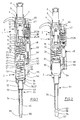
- the pipetting device according to FIGS. 1 and 2 has an elongated handle shaped Housing 1 with an upper housing part 2 and a lower housing part 3. Das Upper housing part 2 with all parts contained forms a drive device and the lower housing part 3 with all parts contained a displacement device.
- the upper housing part 2 forms a base body. It has one upstairs Screw cap 4. From this stands up an adjusting sleeve 5.
- the adjusting sleeve 5 is axially immovable and rotatably mounted in the upper housing part 2.
- a push button 6 is arranged, which still further upwards protrudes.
- the push button 6 is connected to a lifting rod 7, which in the upper housing part. 2 is passed through a spindle 8.
- the spindle 8 is in an internal thread 9 of a Screwed in the upper housing part 2 bearing body 10 is screwed.
- the spindle 8 has a rotatably connected to her driver 11 above.
- the Driver 11 has on the circumference two diametrically opposed radial projections 12.
- the radial projections 12 engage in - not shown - axially extending Grooves of the adjusting sleeve 5 a.
- the spindle 8 has at the bottom an end stop 13 in the form of radially outwardly projecting Ribs. In the position shown, the end stop 13 is a small piece below a shoulder 14 of the bearing body 10 with which it cooperates.
- the lifting rod 7 has a flange 15, which in the position shown at the bottom of the Spindle 8 is applied.
- a spring plate 16 is arranged, with a Collar 17 engages in the bearing body 10.
- the spring plate 16 has an axial bottom protruding, sleeve-shaped bearing portion 18 through which the lifting rod 7 passed is.
- the pipetting device on a spring, not shown, which the lifting rod 7 presses upward, so that the flange 15 at the bottom of the spindle. 8 is applied.
- a coil spring between flange 15 and spring plate 16th arranged.
- a coupling piece in the housing 19th attached at a distance below the spring plate 16 at a distance below the spring plate 16 at a distance below the spring plate 16 is a coupling piece in the housing 19th attached.
- This has several pockets inside 20. These have an axial over the Total length of the coupling piece 19 extended longitudinal groove 21. Furthermore, they have at the top End of the coupling piece 19 a over a small part of the circumference of the coupling piece 19 extended annular groove 22. This has at a distance from the upper end of the Coupling piece 19 below a ramp-like boundary wall, the starting from the longitudinal groove 21 increasingly approximated to the upper end of the coupling piece 19 is. Finally, the pockets 20 at the other end of the annular groove 22 a short axial longitudinal groove portion 23 spaced at a distance from the upper end of Coupling piece 19 ends in the coupling piece 19.
- spring 24 under bias arranged, which is designed as a helical spring.
- the adjusting sleeve 5 has on the circumference a sprocket 25 which is connected to a gear 26th cooperates, a counter 27 with several superimposed on an axis 28th arranged Zumblelwerkssonn 29 drives.
- the counter wheels 29 each have Numerals from 0 to 9, the lower Zählwerksrad 29 is driven by the gear 26.
- the arranged above it Zählwerksson 29 are further rotated by one digit, when the underlying Zählwerksrad 29 passes from 9 to 0.
- the lower housing part 3 can be detachably connected to the upper housing part 2. For this purpose points the lower housing part 3 on the jacket of an upper, cylindrical portion 30th a plurality of outwardly projecting ribs 31 which extend in the axial direction of the cylindrical Section 30 extend.
- the lower housing part 3 has a plurality of below the cylindrical portion 30 conical sections 31 to 33 of different length and taper coming from the Drawing to emerge.
- the conical section 33 is down with a long, light conical projection 34 connected to attach a pipette tip. This one has turn down a short, more conical Aufsteckende 35.
- the lower housing part 3 houses a displacement device in the form of a Piston-cylinder unit 36. This has a arranged in the conical portion 32 Cylinder 37, in which a piston 38 dips. The piston 38 is above a piston rod 39 connected to a pressure piece 40. The piston 38 forms a displaceable Limitation of the cylinder 37.
- the lower housing part 3 has a piston holder 41, the the cylindrical portion 30 bridged above.
- the piston holder 41 has a top one central passage 42 through which a lower portion of the reciprocating piston 7 axially can be passed.
- a Lifting spring 43 arranged, which is designed as a helical spring. By the lifting spring 43 the piston 38 and the piston rod 39 are passed.
- the lifting spring 43 is biased and presses the pressure piece 40 against the piston holder 41, so that the piston 38 is pulled out of the cylinder 37 maximum.
- a connecting passage 44 passes through the boss 34 and connects the cylinder 37 with a muzzle in Aufsteckende 35.
- the pipetting device has a discharge device 45.
- the discharge device 45 has in the upper housing part 2 next to the knob 5, an operating button 46th
- the operating knob 46 is connected to a discharge rod 47 which is parallel to Lifting rod 7 passes through the upper housing part 2 therethrough.
- a transmission 48 is integrated in the discharge rod 47.
- the transmission 48 sets a axial actuating stroke of the actuating knob 46 in a smaller drive stroke with increased strength.
- Suitable transmissions 48 are described in EP 0 992 288 A, and Although generally in the general part of the description and especially in the figure description, which are incorporated by reference into the present application.
- the discharge rod 47 is connected via a further coil spring 49 in the upper housing part. 2 supported, so that the actuating button 46 is pressed into the starting position shown is in which he is pressed against the action of the other coil spring 49.
- the lower end of the discharge rod 47 protrudes into a receptacle 50 at the lower end of the Housing top 2 into it.
- the discharge device 45 has on the lower housing part 3 a discharge sleeve 51. This is on the cylindrical portion 30, the conical portion 32 and the projection 34th guided. Accordingly, the contour of the discharge sleeve 51 is the contours of the aforementioned Sections of the lower housing part 3 aligned. It has the Abschhülse 51 inside stages 52, 53, the postponement of the ejection sleeve 51 after above limit, by at conical sections 31, 33 of the housing lower part 3rd issue.
- the pipetting device can be used as follows:
- the lifting rod engages 7 through the passage 42 through and lies with its lower end to the Pressure piece 40 on.
- a pipette tip 56 is clamped on the lower end of the projection 34.
- the pipette tip 56 has a lower tip opening 57 for receiving and dispensing of liquid.
- the push button 6 For pipetting the push button 6 is pressed down, so that the piston 38th Air displaced from the cylinder 37. Then the pipette tip 56 with its lower Tip opening 57 immersed in the liquid to be pipetted. After that, the Push button 6 released and the lifting rod 7 is under spring action in her Starting position back. Likewise, the piston 38 returns under the action of the spring 43 back to its starting position. Here, the piston 38 sucks liquid through the lower tip opening 57 into the pipette tip 56.
- the lower tip opening 57 of the pipetting device becomes a discharge site aligned.
- the liquid contained in the pipette tip 56 is pressed in the push button 6, re-immersion of the piston 38 in the cylinder 37th and expelling air through the connecting channel 44 delivered. After releasing of the actuating knob 6 drive the lifting rod 7 and the piston 38 by spring force back to the starting position.
- a dispensing head 61 has a multi-channel pipetting device Housing 62, in the eight parallel piston-cylinder devices 63 in a row are arranged. Each piston-cylinder device 63 has a cylinder 64, in the one Plunger 65 is immersed.
- each cylinder 64 designed as a helical spring spring 66 is guided, the bottom rests on a circumferential projection 67 of the cylinder 64.
- the cylinder 64 In the area of the circumferential projection 67, the cylinder 64 is in a guide rail 68 led.
- each cylinder 64 is below the circumferential projection 67 with a conical projection 69 connected to attach a pipette tip 70.
- the cylinder 64 by a fixed in the housing 62nd arranged support plate 71 passed.
- the springs 66 are supported on the underside the support plate 71 from.
- the cylinders 64 have a further circumferential projection above, which is a spring bearing 72 forms.
- Each spring bearing 72 is engaged by a console, not shown, the inside of the wall of the housing 62 protrudes.
- All pistons 65 are at the top in a piston receptacle 73 in the form of a traverse held.
- the piston receptacle 73 has a pin 74 at the top for connection to a Not shown lifting rod, which leads to a drive for the piston 65.
- pistons 65 On all the pistons 65 are further springs 75 designed as helical springs out, which are supported at the bottom of the spring bearing 72 and at the top at the bottom support the piston seat 73.
- an ejector 76 in the form of an angled plate stored. This has in the lower, horizontal leg 77 eight holes through which the Approaches 69 are passed.
- the vertical leg 78 is above a shaft 79 connectable with a discharge bar, not shown.
- the pistons 65 are guided by a piston seal 80 in the cylinder 64.
- the dispensing head 61 is connected to the lifting rod and the discharge rod of a not shown Drive device connected.
- the pistons 65 are connected by means of the pin 74 Lifting rod moves.
- the shaft 79 by means of the lifting rod moved down so that the ejector 76 is moved down and with its leg 77, the pipette tips 70 from the lugs 69 depressed.
Landscapes
- Health & Medical Sciences (AREA)
- Clinical Laboratory Science (AREA)
- Chemical & Material Sciences (AREA)
- Chemical Kinetics & Catalysis (AREA)
- Devices For Use In Laboratory Experiments (AREA)
- Automatic Analysis And Handling Materials Therefor (AREA)
Abstract
Description
- einen Grundkörper,
- mindestens einen vom Grundkörper vorstehenden, axial beweglich am Grundkörper gelagerten Ansatz zum Aufsetzen einer Pipettenspitze,
- eine Feder, über die der Ansatz am Grundkörper abgestützt ist,
- einen dem Ansatz zugeordneten Anschlag, über den der Ansatz axial hinaussteht, wenn er nicht zur Feder hin belastet ist, und
- eine Abwurfeinrichtung zum Lösen der Pipettenspitze von dem Ansatz, die einen dem Ansatz zugeordneten Abwerfer aufweist, wobei Ansatz und Abwerfer relativ zueinander beweglich sind, und die eine mit dem Abwerfer und/oder dem Ansatz wirkverbundene Antriebseinrichtung zum relativen Bewegen von Abwerfer und Ansatz aufweist.
- eine Verdrängungseinrichtung mit einer Verdrängungskammer mit einer verlagerbaren Begrenzung, einem Ansatz zum Verbinden mit einer Pipettenspitze und einem Verbindungskanal zwischen der Verdrängungskammer und dem freien Ende des Ansatzes,
- eine Antriebseinrichtung zum Antreiben der verlagerbaren Begrenzung der Verdrängungseinrichtung mit einem Antriebsorgan, das eine lösbare Wirkverbindung mit der verlagerbaren Begrenzung hat, und
- einer Bajonettverbindung zwischen der Antriebseinrichtung und der Verdrängungseinrichtung, die unter Herstellung der Wirkverbindung zwischen Antriebsorgan und verlagerbarer Begrenzung herstellbar und unter Lösung der Wirkverbindung zwischen Antriebsorgan und verlagerbarer Begrenzung lösbar ist.
- Fig. 1
- eine Hand-Pipettiervorrichtung mit getrennter Kolben-Zylinder-Einheit und Abwerfer im Längsschnitt;
- Fig. 2
- dieselbe Pipettiervorrichtung mit verbundener Kolben-Zylinder-Einheit und Abwerfer im Längsschnitt;
- Fig. 3
- eine Mehrkanal-Pipettiervorrichtung in einem Vertikalschnitt von vom;
- Fig. 4
- dieselbe Mehrkanal-Pipettiervorrichtung in einem Vertikalschnitt von hinten.
Claims (34)
- Pipettiervorrichtung mit,einem Grundkörper (2),mindestens einem vom Grundkörper (2) vorstehenden, axial beweglich am Grundkörper (2) gelagerten Ansatz (34) zum Aufsetzen einer Pipettenspitze (56),einer Feder (24), über die der Ansatz (34) am Grundkörper (2) abgestützt ist,einem dem Ansatz (34) zugeordneten Anschlag (59), über den der Ansatz (34) axial hinaussteht, wenn er nicht zur Feder (24) hin belastet ist, undeiner Abwurfeinrichtung (45) zum Lösen der Pipettenspitze (56) von dem Ansatz (34), die einen dem Ansatz (34) zugeordneten Abwerfer (51) aufweist, wobei Ansatz (34) und Abwerfer (51) relativ zueinander beweglich sind, und die eine mit dem Abwerfer (51) und/oder dem Ansatz (34) wirkverbundene Antriebseinrichtung (46, 47, 48) zum relativen Bewegen von Abwerfer (51) und Ansatz (34) aufweist.
- Pipettiervorrichtung nach Anspruch 1, bei der der Ansatz (34) fest mit einer Verdrängungseinrichtung (36) verbunden ist.
- Pipettiervorrichtung nach Anspruch 1 oder 2, bei der die Verdrängungseinrichtung (36) über die Feder (24) am Grundkörper (2) abgestützt ist.
- Pipettiervorrichtung nach einem der Ansprüche 1 bis 3, bei der die Feder (24) eine in Axialrichtung des Ansatzes (34) erstreckte Schraubenfeder ist.
- Pipettiervorrichtung nach einem der Ansprüche 1 bis 4, die eine vorgespannte Feder (24) aufweist.
- Pipettiervorrichtung nach einem der Ansprüche 1 bis 5, bei der Anschlag (59) axial bezüglich des Ansatzes (34) beweglich ist und eine fest mit dem Grundkörper (2) verbundene Begrenzung (60) für die Axialbewegung des Anschlages (59) zum Grundkörper (2) hin vorhanden ist.
- Pipettiervorrichtung nach einem der Ansprüche 1 bis 6, bei der der Anschlag (59) an dem Abwerfer (51) ausgebildet ist.
- Pipettiervorrichtung nach einem der Ansprüche 1 bis 7, bei der der Ansatz (34) in Richtung von der Feder (24) weg an einem weiteren Anschlag (23) abgestützt ist, gegen den er von der Feder (24) gedrückt wird.
- Pipettiervorrichtung nach einem der Ansprüche 1 bis 8, bei der die Feder (24) austauschbar ist und/oder eine Einrichtung zum Einstellen der Federvorspannung vorhanden ist.
- Pipettiervorrichtung nach einem der Ansprüche 1 bis 9, bei der die Antriebseinrichtung (46, 47, 48) entgegen der Wirkung einer einerseits an einem beweglichen Teil der Antriebseinrichtung (46, 47, 48) und andererseits am Grundkörper (2) abgestützten weiteren Feder (49) betätigbar ist.
- Pipettiervorrichtung nach einem der Ansprüche 1 bis 10, bei der der Grundkörper (2) einen Träger und/oder einen Rahmen und/oder ein Gehäuse aufweist.
- Pipettiervorrichtung nach einem der Ansprüche 1 bis 11, die ein Handgerät und/oder ein stationäres Gerät und/oder ein elektrisch angetriebenes und/oder ein (Halb-)Automat ist.
- Pipettiervorrichtung nach einem der Ansprüche 1 bis 12, die eine Reihe paralleler Ansätze (69) für die Aufnahme von Pipettenspitzen (70) aufweist.
- Pipettiervorrichtung nach Anspruch 13, bei der jeder Ansatz (69) über eine gesonderte Feder (66) am Grundkörper (62) abgestützt ist.
- Pipettiervorrichtung nach Anspruch 13 oder 14, bei der den Ansätzen (69) eine gemeinsamer Abwerfer (76) zugeordnet ist.
- Pipettiervorrichtung nach einem der Ansprüche 1 bis 15 miteiner Verdrängungseinrichtung (36) mit einer Verdrängungskammer (37) mit einer verlagerbaren Begrenzung (38), einem Ansatz (34) zum Verbinden mit einer Pipettenspitze (56) und einem Verbindungskanal (44) zwischen der Verdrängungskammer (37) und dem freien Ende des Ansatzes (34),einer Antriebseinrichtung (6, 7, 8) zum Antreiben der verlagerbaren Begrenzung (38) der Verdrängungseinrichtung (36) mit einem Antriebsorgan (7), das eine lösbare Wirkverbindung mit der verlagerbaren Begrenzung (38) hat, undeiner Bajonettverbindung (19, 22, 30, 31 ) zwischen der Antriebseinrichtung (6, 7, 8) und der Verdrängungseinrichtung (36), die unter Herstellung der Wirkverbindung zwischen Antriebsorgan (7) und verlagerbarer Begrenzung (38) herstellbar und unter Lösung der Wirkverbindung zwischen Antriebsorgan (7) und verlagerbarer Begrenzung (38) lösbar ist.
- Pipettiervorrichtung nach Anspruch 16, bei der das Antriebsorgan (7) eine parallel zur Längsachse der Bajonettverbindung verlagerbare Hubstange der Antriebseinrichtung (6, 7, 8) ist und die Verdrängungseinrichtung (36) eine mit der Begrenzung (38) verbundene, quer zur Hubstange (7) gerichtete Kontaktfläche aufweist, die von einer Hubfeder (43) gegen das Ende der Hubstange (7) gedrückt ist.
- Pipettiervorrichtung nach Anspruch 17, bei der die Kontaktfläche an einem über eine Stange (39) mit der Begrenzung (38) verbundenen Druckstück (40) ausgebildet ist und einenends am Druckstück (40) und anderenends an der Verdrängungskammer (37) eine als Schraubenfeder ausgebildete Hubfeder (43) abgestützt ist.
- Pipettiervorrichtung nach einem der Ansprüche 16 bis 18, bei der die Antriebseinrichtung (6, 7, 8) eine zylindrische Aufnahme (19) hat, die an einem Ende eine Öffnung aufweist, durch die die zylindrische Aufnahme (19) in axialer Richtung von außen zugänglich ist, die mindestens eine axial gerichtete Längsnut (21) aufweist, die mit einer in Umfangsrichtung der zylindrischen Aufnahme (19) gerichteten Ringnut (22) verbunden ist, und bei der die Verdrängungseinrichtung (36) auf einem zylindrischen Abschnitt (30) mindestens einen nach außen vorstehenden Vorsprung (31) aufweist, wobei der zylindrische Abschnitt (30) in axialer Richtung der zylindrischen Aufnahme (19) durch die Öffnung in die Aufnahme (19) und mit dem Vorsprung (31) in die Längsnut (21) einführbar und mit dem Vorsprung (31) in die Ringnut (22) eindrehbar ist.
- Pipettiervorrichtung nach einem der Ansprüche 16 bis 19, bei der die Ringnut (22) in einem Abstand von der Längsnut (21) eine in axialer Richtung der Aufnahme (19) erstreckte Begrenzungswand aufweist, bis zu der der Vorsprung (31) drehbar ist.
- Pipettiervorrichtung nach Anspruch 19 oder 20, bei der die Ringnut (22) in einem Abstand von der Längsnut (21) mit einem parallel zu dieser verlaufenden Längsnutabschnitt (23) verbunden ist, der in einem Abstand von der Öffnung endet.
- Pipettiervorrichtung nach einem der Ansprüche 19 bis 21, bei der die Ringnut (22) eine rampenartig verlaufende Begrenzungswand aufweist, deren Abstand von der Öffnung mit zunehmendem Abstand von der Längsnut (21) ansteigt.
- Pipettiervorrichtung nach einem der Ansprüche 19 bis 22, bei der die Längsnut (21), die Ringnut (22) und wahlweise der Längsnutabschnitt (23) mit einem zylindrischen Koppelstück (19) ausgebildet sind, das die Aufnahme der Antriebseinrichtung (6, 7, 8) bildet und in dieser befestigt ist.
- Pipettiervorrichtung nach einem der Ansprüche 16 bis 23, bei der die Antriebseinrichtung (6, 7, 8) eine Feder (24) aufweist, die gegen die über die Bajonettverbindung (19, 22, 30, 31) mit der Antriebseinrichtung (6, 7, 8) verbundene Verdrängungseinrichtung (36) drückt.
- Pipettiervorrichtung nach Anspruch 24, bei der die Feder (24) an einer weiteren Öffnung der Aufnahme (19) angeordnet ist, die der Öffnung zum axialen Einführen der Verdrängungseinrichtung (36) gegenüberliegt.
- Pipettiervorrichtung nach Anspruch 24 oder 25, bei der die Feder (24) eine Schraubenfeder ist, die sich an einer innen liegenden Stirnseite des Koppelstückes (19) abstützt.
- Pipettiervorrichtung nach einem der Ansprüche 25 bis 26, bei der die Längsnut (21) und/oder die Ringnut (22) und/oder der Längsnutabschnitt (23) zur weiteren Öffnung hin geöffnet sind.
- Pipettiervorrichtung nach einem der Ansprüche 16 bis 27, bei der die Verdrängungseinrichtung (36) eine Kolben-Zylinder-Einrichtung mit einem Zylinder (37) und einem darin verschiebbaren Kolben (38) ist und der Kolben (38) die verlagerbare Begrenzung aufweist.
- Pipettiervorrichtung nach einem der Ansprüche 16 bis 28, bei der der Ansatz (34) koaxial zur Längsachse der Bajonettverbindung (19, 22, 30, 31) ausgerichtet ist.
- Pipettiervorrichtung nach einem der Ansprüche 16 bis 29, bei der der Ansatz (34) fest mit der Verdrängungskammer (37) verbunden ist.
- Pipettiervorrichtung nach einem der Ansprüche 16 bis 30, mit einer Abwurfeinrichtung (45) zum Lösen einer Pipettenspitze (56) von dem Ansatz (34), die einen an der Antriebseinrichtung (6, 7, 8) angeordneten Abwurfantrieb (46, 47, 48), einen an der Verdrängungseinrichtung (36) angeordneten Abwerfer (51) und eine in Richtung der Längsachse der Bajonettverbindung (19, 22, 30, 31) gerichtete, lösbare axiale Klemmverbindung (47, 55) zwischen Abwurfantrieb (45) und Abwerfer (51) aufweist.
- Pipettiervorrichtung nach Anspruch 31, bei der der Abwurfantrieb (45) eine von der Antriebseinrichtung parallel zur Bajonettverbindung (19, 22, 30, 31) vorstehende Abwurfstange (47) und der Abwerfer (51) eine zum Ansatz (34) parallele, axiale Bohrung (55) aufweist, die mit der Abwurfstange (47) preßverbunden ist.
- Pipettiervorrichtung nach Anspruch 32, bei der der Abwerfer (51) an der Verdrängungseinrichtung (36) geführt ist.
- Pipettiervorrichtung nach einem der Ansprüche 16 bis 33, bei der der Abwerfer (51) eine an der Verdrängungseinrichtung (36) geführte Hülse ist.
Priority Applications (1)
| Application Number | Priority Date | Filing Date | Title |
|---|---|---|---|
| EP10011574.0A EP2263800A3 (de) | 2004-01-21 | 2005-01-07 | Pipettiervorrichtung mit einer Abwurfeinrichtung für Pipettenspitzen |
Applications Claiming Priority (2)
| Application Number | Priority Date | Filing Date | Title |
|---|---|---|---|
| DE102004003433A DE102004003433B4 (de) | 2004-01-21 | 2004-01-21 | Pipettiervorrichtung mit einer Abwurfeinrichtung für Pipettenspitzen |
| DE102004003433 | 2004-01-21 |
Related Child Applications (2)
| Application Number | Title | Priority Date | Filing Date |
|---|---|---|---|
| EP10011574.0A Division EP2263800A3 (de) | 2004-01-21 | 2005-01-07 | Pipettiervorrichtung mit einer Abwurfeinrichtung für Pipettenspitzen |
| EP10011574.0A Division-Into EP2263800A3 (de) | 2004-01-21 | 2005-01-07 | Pipettiervorrichtung mit einer Abwurfeinrichtung für Pipettenspitzen |
Publications (3)
| Publication Number | Publication Date |
|---|---|
| EP1557222A2 true EP1557222A2 (de) | 2005-07-27 |
| EP1557222A3 EP1557222A3 (de) | 2007-05-09 |
| EP1557222B1 EP1557222B1 (de) | 2014-11-12 |
Family
ID=34625769
Family Applications (2)
| Application Number | Title | Priority Date | Filing Date |
|---|---|---|---|
| EP05000212.0A Expired - Lifetime EP1557222B1 (de) | 2004-01-21 | 2005-01-07 | Pipettiervorrichtung mit einer Abwurfeinrichtung für Pipettenspitzen |
| EP10011574.0A Withdrawn EP2263800A3 (de) | 2004-01-21 | 2005-01-07 | Pipettiervorrichtung mit einer Abwurfeinrichtung für Pipettenspitzen |
Family Applications After (1)
| Application Number | Title | Priority Date | Filing Date |
|---|---|---|---|
| EP10011574.0A Withdrawn EP2263800A3 (de) | 2004-01-21 | 2005-01-07 | Pipettiervorrichtung mit einer Abwurfeinrichtung für Pipettenspitzen |
Country Status (3)
| Country | Link |
|---|---|
| US (1) | US7434484B2 (de) |
| EP (2) | EP1557222B1 (de) |
| DE (1) | DE102004003433B4 (de) |
Cited By (3)
| Publication number | Priority date | Publication date | Assignee | Title |
|---|---|---|---|---|
| EP2165765A1 (de) | 2008-09-12 | 2010-03-24 | Eppendorf Ag | Pipettiervorrichtung mit Doppelgewinde |
| EP2210667A1 (de) * | 2009-01-19 | 2010-07-28 | Eppendorf Ag | Pipette mit Abwurfeinrichtung |
| CN106470760A (zh) * | 2014-07-04 | 2017-03-01 | 埃佩多夫股份公司 | 用于操作注射器的移液器 |
Families Citing this family (29)
| Publication number | Priority date | Publication date | Assignee | Title |
|---|---|---|---|---|
| CH708024B8 (de) * | 2005-12-20 | 2015-01-15 | Tpp Techno Plastic Products Ag | Verfahren zur Herstellung einer Pipette. |
| US20090071267A1 (en) * | 2007-09-17 | 2009-03-19 | Greg Mathus | Pipette tip ejection mechanism |
| CN102414550B (zh) | 2009-04-27 | 2014-07-16 | Ei频谱有限责任公司 | 移液器仪器 |
| DE102009051654B4 (de) * | 2009-10-30 | 2013-01-03 | Eppendorf Ag | Dosiervorrichtung für Flüssigkeiten und Verfahren zum Dosieren von Flüssigkeiten |
| JP2011115759A (ja) * | 2009-12-07 | 2011-06-16 | Fukae Kasei Kk | ピペット装置 |
| WO2011148432A1 (ja) * | 2010-05-28 | 2011-12-01 | 栄研化学株式会社 | ピペット |
| DE102010047126A1 (de) * | 2010-10-04 | 2012-04-05 | Eppendorf Ag | Pipette |
| PL2633913T3 (pl) | 2012-03-01 | 2020-03-31 | Eppendorf Ag | Urządzenie do pipetowania i wielokanałowe urządzenie do pipetowania |
| US9358538B2 (en) | 2012-04-30 | 2016-06-07 | The Regents Of The University Of Michigan | High resolution pipette |
| EP2735369B1 (de) | 2012-11-23 | 2017-04-26 | Eppendorf Ag | Mehrkanalpipette |
| US9815053B2 (en) * | 2013-01-15 | 2017-11-14 | Mettler-Toledo Rainin, LLC | Liquid end assembly for a multichannel air displacement pipette |
| USD772426S1 (en) | 2014-01-13 | 2016-11-22 | Gilson, Inc. | Pipette system cartridge |
| FR3040896B1 (fr) * | 2015-09-15 | 2017-10-13 | Gilson Sas | Pipette de prelevement comprenant un organe de commande a double fonction d'ejection de cone et de deverrouillage du systeme de reglage de volume |
| WO2017064089A1 (en) | 2015-10-13 | 2017-04-20 | F. Hoffmann-La Roche Ag | Pipetting device for an apparatus for processing a sample or reagent, apparatus for processing a sample or reagent and method for pipetting a sample or reagent |
| PL3260822T3 (pl) | 2016-06-21 | 2021-02-08 | Eppendorf Ag | Wielokanałowa strzykawka do stosowania z urządzeniem dozującym |
| DE102016111910A1 (de) | 2016-06-29 | 2018-01-04 | Eppendorf Ag | Dosierkopf, Dosiervorrichtung umfassend einen Dosierkopf und Verfahren zum Dosieren mittels eines Dosierkopfes |
| DE102016111912A1 (de) | 2016-06-29 | 2018-01-04 | Eppendorf Ag | Dosierkopf, Dosiervorrichtung umfassend einen Dosierkopf und Verfahren zum Dosieren mittels eines Dosierkopfes |
| DE102016121816A1 (de) * | 2016-11-14 | 2018-05-17 | Ika-Werke Gmbh & Co. Kg | Fluidabgabeeinheit und Handdosiervorrichtung mit wenigstens einer Fluidabgabeeinheit |
| JP6865510B2 (ja) * | 2017-06-01 | 2021-04-28 | 株式会社エー・アンド・デイ | マルチチャンネルピペット |
| US10744498B2 (en) | 2017-09-19 | 2020-08-18 | Mettler-Toledo Rainin, LLC | Pipette quickset volume adjustment mechanism |
| EP3477307B1 (de) * | 2017-10-24 | 2020-07-22 | F. Hoffmann-La Roche AG | Pipettiervorrichtung und pipettiervorrichtungpositionierungssystem |
| EP3666379A1 (de) | 2018-12-14 | 2020-06-17 | Eppendorf AG | Pipettierkopf, pipettiervorrichtung umfassend einen pipettierkopf und verfahren zum pipettieren mittels eines pipettierkopfes |
| EP3851191A1 (de) * | 2020-01-17 | 2021-07-21 | Eppendorf AG | Verfahren zum betreiben einer kolbenhubpipette, kolbenhubpipette, datenverarbeitungsgerät und system |
| WO2021163437A1 (en) | 2020-02-14 | 2021-08-19 | DeNovix, Inc. | Dynamic broad volumetric range pipette |
| CN111744567B (zh) * | 2020-06-24 | 2021-03-30 | 巨爱宁 | 一种化验科室用移液枪 |
| TWI824896B (zh) * | 2022-08-18 | 2023-12-01 | 創茂生技股份有限公司 | 旋轉式移液裝置 |
| US12544750B2 (en) | 2022-08-31 | 2026-02-10 | DeNovix Inc. | Multi-tiered pipette tip holder and ejection mechanism for a dynamic broad volumetric range pipette |
| TWI840043B (zh) * | 2022-12-22 | 2024-04-21 | 緯創資通股份有限公司 | 多功能移液器及自動化檢測機器 |
| DE102023131370B3 (de) * | 2023-11-10 | 2025-02-27 | Eppendorf Se | Mehrkanal-Unterteil für eine Fluidübertragungsvorrichtung sowie Fluidübertragungsvorrichtung |
Family Cites Families (37)
| Publication number | Priority date | Publication date | Assignee | Title |
|---|---|---|---|---|
| FR2287941A1 (fr) * | 1974-10-15 | 1976-05-14 | Marteau D Autry Eric | Dispositif d'ejection de l'embout amovible d'une pipette |
| US4009611A (en) * | 1976-05-13 | 1977-03-01 | Oxford Laboratories Inc. | Hand-held micropipettor with improved pipette tip ejector |
| US4086062A (en) * | 1977-02-23 | 1978-04-25 | Hach Chemical Company | Digital titration device |
| DE2711124C2 (de) * | 1977-03-15 | 1979-05-10 | Labora Mannheim Gmbh Fuer Labortechnik, 6800 Mannheim | Handpipette |
| US4187724A (en) * | 1978-01-11 | 1980-02-12 | Indicon Inc. | Replaceable tip for a pipette |
| US4567780A (en) * | 1984-03-12 | 1986-02-04 | American Hospital Supply Corporation | Hand-held pipette with disposable capillary |
| US4824641A (en) * | 1986-06-20 | 1989-04-25 | Cetus Corporation | Carousel and tip |
| JPH0434456Y2 (de) * | 1987-05-02 | 1992-08-17 | ||
| CA1321940C (en) * | 1987-05-02 | 1993-09-07 | Teruaki Itoh | Apparatus for distributing sample liquid |
| JP2701900B2 (ja) * | 1988-12-20 | 1998-01-21 | 株式会社ニチリョー | マルチピペット |
| US5104624A (en) * | 1989-10-20 | 1992-04-14 | Costar Corporation | Pipetter |
| FI921765A0 (fi) * | 1992-04-21 | 1992-04-21 | Labsystems Oy | Med en spetsavlaegsnare foersedd pipett. |
| FI90207C (fi) * | 1992-05-04 | 1994-01-10 | Wallac Oy | Pipettilaitteisto |
| US5614153A (en) * | 1995-05-26 | 1997-03-25 | Rainin Instrument Co., Inc. | Pipette tip ejector |
| US5700959A (en) * | 1995-07-14 | 1997-12-23 | Rainin Instrument Co., Inc. | Manual pipette with magnet assist |
| US6123905A (en) * | 1997-01-17 | 2000-09-26 | Matrix Technologies Corporation | Pipettor including an indicator and method of use |
| US6499363B1 (en) * | 1997-12-12 | 2002-12-31 | The Sailor Pen Co., Ltd. | Tip for pipette and pipette with the same |
| FI107025B (fi) * | 1998-06-10 | 2001-05-31 | Biohit Oyj | Imulaite ja menetelmä kertakäyttökärjen irroittamiseksi |
| PL190746B1 (pl) | 1998-08-05 | 2006-01-31 | P Z Htl Sa | Urządzenie do odrzucania wymiennej końcówki w pipecie |
| DE19835833A1 (de) * | 1998-08-07 | 2000-02-17 | Max Planck Gesellschaft | Dosierkopf zur parallelen Bearbeitung einer Vielzahl von Fluidproben |
| DE19845950C1 (de) * | 1998-10-06 | 2000-03-23 | Eppendorf Geraetebau Netheler | Pipettiersystem mit einer Pipettiervorrichtung und mindestens einer daran lösbar befestigten Pipettenspitze |
| US6197259B1 (en) * | 1998-11-06 | 2001-03-06 | Rainin Instrument Co., Inc. | Easy eject pipette tip |
| US6168761B1 (en) * | 1998-11-06 | 2001-01-02 | Rainin Instrument Co., Inc. | Pipette with improved pipette tip and mounting shaft |
| US6833114B1 (en) * | 1999-05-18 | 2004-12-21 | Socorex Isba S.A. | Pipette with tip ejector |
| US6532837B1 (en) * | 2000-02-03 | 2003-03-18 | Rainin Instrument, Llc | Pipette device with tip ejector utilizing stored energy |
| US6428750B1 (en) * | 2000-02-17 | 2002-08-06 | Rainin Instrument, Llc | Volume adjustable manual pipette with quick set volume adjustment |
| DE10013511A1 (de) * | 2000-03-20 | 2001-10-11 | Brand Gmbh & Co Kg | Mehrkanal-Pipettiereinrichtung sowie Pipettenschaft dafür |
| FR2807340B1 (fr) * | 2000-04-07 | 2002-12-06 | Gilson Sa | Pipette de prelevement d'echantillons liquides a mecanisme d'ejecteur de cone |
| PL192826B1 (pl) | 2000-06-07 | 2006-12-29 | P Z Htl Sa | Moduł pipety wielokanałowej |
| JP2004501745A (ja) * | 2000-06-26 | 2004-01-22 | ビスタラブ テクノロジーズ インク | 自動ピペット識別および先端部取外し |
| JP3719375B2 (ja) * | 2000-07-26 | 2005-11-24 | ニプロ株式会社 | 溶液調製装置 |
| DE10040849A1 (de) * | 2000-08-21 | 2002-03-21 | Mwg Biotech Ag | Pipettierkopf für einen Roboter mit mehreren Pipettierspitzen |
| FI20002241A0 (fi) * | 2000-10-11 | 2000-10-11 | Labsystems Oy | Säädettävä pipetti |
| FI20010972A0 (fi) * | 2001-05-09 | 2001-05-09 | Thermo Labsystems Oy | Kärkisäiliöpipetti |
| DE10135963B4 (de) * | 2001-07-24 | 2005-09-29 | Fraunhofer-Gesellschaft zur Förderung der angewandten Forschung e.V. | Vorrichtung zum Pipettieren einer Flüssigkeit |
| JP4148894B2 (ja) * | 2001-10-16 | 2008-09-10 | マトリックス・テクノロジイズ・コーポレーション | 手持ち式ピペット |
| US6967004B2 (en) * | 2001-10-30 | 2005-11-22 | Rainin Instrument, Llc | Pipette with improved pipette tip and mounting shaft |
-
2004
- 2004-01-21 DE DE102004003433A patent/DE102004003433B4/de not_active Expired - Lifetime
-
2005
- 2005-01-07 EP EP05000212.0A patent/EP1557222B1/de not_active Expired - Lifetime
- 2005-01-07 EP EP10011574.0A patent/EP2263800A3/de not_active Withdrawn
- 2005-01-20 US US11/038,837 patent/US7434484B2/en not_active Expired - Lifetime
Cited By (7)
| Publication number | Priority date | Publication date | Assignee | Title |
|---|---|---|---|---|
| EP2165765A1 (de) | 2008-09-12 | 2010-03-24 | Eppendorf Ag | Pipettiervorrichtung mit Doppelgewinde |
| DE102008048252A1 (de) | 2008-09-12 | 2010-04-15 | Eppendorf Ag | Pipettiervorrichtung |
| US8297134B2 (en) | 2008-09-12 | 2012-10-30 | Eppendorf Ag | Pipetting device |
| EP2210667A1 (de) * | 2009-01-19 | 2010-07-28 | Eppendorf Ag | Pipette mit Abwurfeinrichtung |
| CN106470760A (zh) * | 2014-07-04 | 2017-03-01 | 埃佩多夫股份公司 | 用于操作注射器的移液器 |
| CN106470760B (zh) * | 2014-07-04 | 2019-06-07 | 埃佩多夫股份公司 | 用于操作注射器的移液器 |
| US10507463B2 (en) | 2014-07-04 | 2019-12-17 | Eppendorf Ag | Pipette for activating a syringe |
Also Published As
| Publication number | Publication date |
|---|---|
| DE102004003433B4 (de) | 2006-03-23 |
| US20050155439A1 (en) | 2005-07-21 |
| EP1557222A3 (de) | 2007-05-09 |
| EP2263800A3 (de) | 2014-05-21 |
| DE102004003433A1 (de) | 2005-08-25 |
| EP1557222B1 (de) | 2014-11-12 |
| EP2263800A2 (de) | 2010-12-22 |
| US7434484B2 (en) | 2008-10-14 |
Similar Documents
| Publication | Publication Date | Title |
|---|---|---|
| EP1557222B1 (de) | Pipettiervorrichtung mit einer Abwurfeinrichtung für Pipettenspitzen | |
| EP1559480B1 (de) | Pipettiervorrichtung mit einer Verdrängungseinrichtung und einer damit lösbar verbundenen Antriebseinrichtung | |
| EP2633913B1 (de) | Pipettiervorrichtung und Mehrkanal-Pippettiervorrichtung | |
| EP0062206B1 (de) | Pneumatisch-hydraulisches Blindnietgerät | |
| EP2735369B1 (de) | Mehrkanalpipette | |
| EP1084798B1 (de) | Hydraulisches Handpressgerät | |
| EP2425896B1 (de) | Spritze für den Gebrauch mit einer Dosiervorrichtung | |
| EP3680016B1 (de) | Pipette für den gebrauch mit einer pipettenspitze | |
| EP3478418A1 (de) | Dosierkopf, dosiervorrichtung umfassend einen dosierkopf und verfahren zum dosieren mittels eines dosierkopfes | |
| EP1598113B1 (de) | Pipette | |
| DE102007010299A1 (de) | Handpipettiervorrichtung | |
| EP2659978B1 (de) | Pipette mit Verriegelungssystem | |
| DE102005023203A1 (de) | Pipette | |
| EP3793738A1 (de) | Pipettierkopf, pipettiervorrichtung umfassend einen pipettierkopf und verfahren zum pipettieren mittels eines pipettierkopfes | |
| EP1759768B1 (de) | Pipettiervorrichtung | |
| DE19708151C2 (de) | Pipettiervorrichtung | |
| DE102006031460B4 (de) | Pipettiervorrichtung | |
| EP3680017B1 (de) | Pipette für den gebrauch mit einer pipettenspitze | |
| EP2626134B1 (de) | Pipette | |
| EP2210667B1 (de) | Dosiervorrichtung mit Abwurfeinrichtung | |
| DE1465115A1 (de) | Durch ein Druckmedium betaetigtes Presswerkzeug | |
| DE10355914B3 (de) | Pipettiervorrichtung mit einer Abwurfeinrichtung für Pipettenspitzen | |
| DE4127269C2 (de) | Pneumatisches Schraubgerät | |
| DE102023131378B3 (de) | Pipette mit verstellbarem Pipettiervolumen und Verriegelungssystem | |
| DE102004055562B4 (de) | Handhabbares Dosiersystem |
Legal Events
| Date | Code | Title | Description |
|---|---|---|---|
| PUAI | Public reference made under article 153(3) epc to a published international application that has entered the european phase |
Free format text: ORIGINAL CODE: 0009012 |
|
| AK | Designated contracting states |
Kind code of ref document: A2 Designated state(s): AT BE BG CH CY CZ DE DK EE ES FI FR GB GR HU IE IS IT LI LT LU MC NL PL PT RO SE SI SK TR |
|
| AX | Request for extension of the european patent |
Extension state: AL BA HR LV MK YU |
|
| PUAL | Search report despatched |
Free format text: ORIGINAL CODE: 0009013 |
|
| AK | Designated contracting states |
Kind code of ref document: A3 Designated state(s): AT BE BG CH CY CZ DE DK EE ES FI FR GB GR HU IE IS IT LI LT LU MC NL PL PT RO SE SI SK TR |
|
| AX | Request for extension of the european patent |
Extension state: AL BA HR LV MK YU |
|
| 17P | Request for examination filed |
Effective date: 20070420 |
|
| 17Q | First examination report despatched |
Effective date: 20070706 |
|
| AKX | Designation fees paid |
Designated state(s): DE FR GB IT |
|
| GRAP | Despatch of communication of intention to grant a patent |
Free format text: ORIGINAL CODE: EPIDOSNIGR1 |
|
| INTG | Intention to grant announced |
Effective date: 20140623 |
|
| GRAS | Grant fee paid |
Free format text: ORIGINAL CODE: EPIDOSNIGR3 |
|
| GRAA | (expected) grant |
Free format text: ORIGINAL CODE: 0009210 |
|
| AK | Designated contracting states |
Kind code of ref document: B1 Designated state(s): DE FR GB IT |
|
| REG | Reference to a national code |
Ref country code: GB Ref legal event code: FG4D Free format text: NOT ENGLISH |
|
| REG | Reference to a national code |
Ref country code: DE Ref legal event code: R096 Ref document number: 502005014586 Country of ref document: DE Effective date: 20141224 |
|
| REG | Reference to a national code |
Ref country code: DE Ref legal event code: R097 Ref document number: 502005014586 Country of ref document: DE |
|
| PLBE | No opposition filed within time limit |
Free format text: ORIGINAL CODE: 0009261 |
|
| STAA | Information on the status of an ep patent application or granted ep patent |
Free format text: STATUS: NO OPPOSITION FILED WITHIN TIME LIMIT |
|
| 26N | No opposition filed |
Effective date: 20150813 |
|
| REG | Reference to a national code |
Ref country code: FR Ref legal event code: PLFP Year of fee payment: 12 |
|
| REG | Reference to a national code |
Ref country code: FR Ref legal event code: PLFP Year of fee payment: 13 |
|
| REG | Reference to a national code |
Ref country code: FR Ref legal event code: PLFP Year of fee payment: 14 |
|
| REG | Reference to a national code |
Ref country code: FR Ref legal event code: PLFP Year of fee payment: 19 |
|
| REG | Reference to a national code |
Ref country code: DE Ref legal event code: R081 Ref document number: 502005014586 Country of ref document: DE Owner name: EPPENDORF SE, DE Free format text: FORMER OWNER: EPPENDORF AG, 22339 HAMBURG, DE |
|
| P01 | Opt-out of the competence of the unified patent court (upc) registered |
Effective date: 20230527 |
|
| PGFP | Annual fee paid to national office [announced via postgrant information from national office to epo] |
Ref country code: DE Payment date: 20240119 Year of fee payment: 20 Ref country code: GB Payment date: 20240123 Year of fee payment: 20 |
|
| PGFP | Annual fee paid to national office [announced via postgrant information from national office to epo] |
Ref country code: IT Payment date: 20240122 Year of fee payment: 20 Ref country code: FR Payment date: 20240124 Year of fee payment: 20 |
|
| REG | Reference to a national code |
Ref country code: DE Ref legal event code: R071 Ref document number: 502005014586 Country of ref document: DE |
|
| REG | Reference to a national code |
Ref country code: GB Ref legal event code: PE20 Expiry date: 20250106 |
|
| PG25 | Lapsed in a contracting state [announced via postgrant information from national office to epo] |
Ref country code: GB Free format text: LAPSE BECAUSE OF EXPIRATION OF PROTECTION Effective date: 20250106 |