EP1555379A1 - Rideau à lammes - Google Patents
Rideau à lammes Download PDFInfo
- Publication number
- EP1555379A1 EP1555379A1 EP04405034A EP04405034A EP1555379A1 EP 1555379 A1 EP1555379 A1 EP 1555379A1 EP 04405034 A EP04405034 A EP 04405034A EP 04405034 A EP04405034 A EP 04405034A EP 1555379 A1 EP1555379 A1 EP 1555379A1
- Authority
- EP
- European Patent Office
- Prior art keywords
- slats
- slat
- guide
- guide surface
- sliding movement
- Prior art date
- Legal status (The legal status is an assumption and is not a legal conclusion. Google has not performed a legal analysis and makes no representation as to the accuracy of the status listed.)
- Withdrawn
Links
Images


Classifications
-
- E—FIXED CONSTRUCTIONS
- E04—BUILDING
- E04F—FINISHING WORK ON BUILDINGS, e.g. STAIRS, FLOORS
- E04F10/00—Sunshades, e.g. Florentine blinds or jalousies; Outside screens; Awnings or baldachins
- E04F10/08—Sunshades, e.g. Florentine blinds or jalousies; Outside screens; Awnings or baldachins of a plurality of similar rigid parts, e.g. slabs, lamellae
- E04F10/10—Sunshades, e.g. Florentine blinds or jalousies; Outside screens; Awnings or baldachins of a plurality of similar rigid parts, e.g. slabs, lamellae collapsible or extensible; metallic Florentine blinds; awnings with movable parts such as louvres
-
- E—FIXED CONSTRUCTIONS
- E06—DOORS, WINDOWS, SHUTTERS, OR ROLLER BLINDS IN GENERAL; LADDERS
- E06B—FIXED OR MOVABLE CLOSURES FOR OPENINGS IN BUILDINGS, VEHICLES, FENCES OR LIKE ENCLOSURES IN GENERAL, e.g. DOORS, WINDOWS, BLINDS, GATES
- E06B7/00—Special arrangements or measures in connection with doors or windows
- E06B7/02—Special arrangements or measures in connection with doors or windows for providing ventilation, e.g. through double windows; Arrangement of ventilation roses
- E06B7/08—Louvre doors, windows or grilles
Definitions
- the invention relates to a slat device with a plurality of slats, in particular of Glass, for opening, in particular, as a roof or wall of a building serving surface, in which the slats from an inside of the building ago are held and wherein at least one blade is mounted so that they have a Pivoting movement out of the surface and a sliding movement along the Can perform surface.
- each lamella is individual and Stored pivotally mounted, wherein the various pivot mechanisms via a coupled common drive, so that all slats are opened together can (DE 35 00 114 C1, CH 686 633, DE 41 02 922 C1, DE 4227278 C2, EP 0 568 495 B1, DE 196 45 802 C1, DE 101 23 565 C1).
- the other type is the Slats attached to a scissors mechanism, which the slats simultaneously pivots and retracts so that a completely free opening can be formed (DE 40 20 334 C2).
- the lamella glazing of the former type is particularly suitable for normally inhabited and isolated buildings.
- the advantage of the individual swivel mechanism is namely, that the slats are opened slightly in a pitched roof without the risk of water entering during a sudden rain fall.
- the blades guided by a scissor mechanism have the Advantage that the roof can be completely withdrawn in fine weather, so that the user can sit in the open air. (Further, with such Scissors mechanism also glass doors or glass fronts are formed.) It is however It is not possible to open the slats halfway without simultaneously pulling the roof halfway becomes.
- the object of the invention is a belonging to the aforementioned technical field Lamella device to create, which allows on the one hand the slats panning without being withdrawn at the same time, on the other hand, retract the blades to release the opening.
- the lamellar device which is a surface associated with the device closes, at least one, but typically several slats.
- the slats are held from an inside of the building (and not at the narrow ends the lamellae, as would be common, for example, with metal gates).
- At least one lamella is mounted so that they pivot out of said surface and can perform a sliding movement along the surface.
- the roof can be opened slightly without the slats retracted at the same time Need to become.
- the conservatory is thus ventilated and at the same time covered (eg protected against sudden rain).
- the conservatory can be in an above open patio.
- At least one louver is pivotable stored a sliding plate carrier.
- the pivotable mounting of the slat on the disk carrier forms (together with the pivot drive) the one adjusting mechanism and the slidable mounting of the disk carrier on a linear Guide surface (together with a linear drive) the other adjustment mechanism.
- the plate carriers of the different lamellae can be completely independent of each other be. It is therefore conceivable that the structural design of the linear adjustment mechanism such is that a single (or each individual) plate carrier individually and is independent of the others. In contrast, can also be provided be that two or more plate carrier are coupled in motion, so that they can be moved (shifted) synchronously or successively to each other.
- the blade is first swung open and then moved.
- the Pivoting motion geometrically represents a rotation about a geometric one Axis.
- This geometric axis is usually not in the area, which is defined by the glass fins as a whole, but at a distance to this level.
- the adjusting mechanism for the pivoting movement comprises z. B. a roller guide system for a lever element connected to the lamella. So the lever element has a roller which is guided on a guide track of the roller guide system. By the interaction of the roller with the guide track or guide curve of the roller guide system the pivoting movement is controlled or generated.
- the roller guide or a part thereof may be displaceable relative to the pivot axis of the slat.
- roller guide instead of the roller guide and a slide guide can be used.
- a slide guide can, for example be realized in that bolts are guided in a guide slot.
- Adjustment mechanism for the pivoting movement may also have a servo motor.
- the pivoting movement is associated by one of the lamella Server engine turned. Although this brings an increased mechanical or electrical Effort with it, but allows a freer control of slats movement.
- the guide means for controlling the movement of the Slats can be designed so that the slats in each pivot position a have a clearly defined position (forced operation). This way you can be sure be that the slats can not "flutter” when they are from a sudden gust of wind be recorded. In many cases, however, the weight of the glass lamella be sufficiently large, so that a "one-sided" leadership (i.e., a support surface for the Guide rollers) provides sufficient security, against unwanted movements.
- the adjustment mechanism for the displacement of the slats preferably comprises a flexible coupling mechanism z.
- the coupling mechanism gives the maximum distance of the slats to each other.
- the flexibility of the coupling mechanism makes it possible to bring the slats close to each other during retraction.
- each displaceable plate carrier an independent linear drive (For example, a gear drive), which is electronically controlled on a certain position can be brought.
- the Linear drive comprises a drive spindle which extends over the entire length of the linear movement the lamellae extends, and that each lamella is a coupling mechanism is assigned, which in each case at a certain, controlled time to the Coupling drive spindle and causes the take away of the lamella.
- Drive spindle can also be provided a rope or a chain on which the Can engage and disengage the disk carrier.
- a cable or chain hoist can be provided be, which engages the lowest lamellar element and this pulls upwards.
- the drive motor can be accommodated above.
- Preferably is with worked an endless chain hoist.
- the lowermost plate element can be coupled with a spindle drive.
- the lamellar element can then be transported upwards by means of the threaded spindle be, with the remaining lamellar elements are collected in order.
- the Threaded spindle can absorb relatively high tensile forces.
- the roller guide system for generating the pivoting movement may, for example, each lamella form a guideway having a recess.
- each lamella attached roll is guided into the depression, then the Slat brought into the closed position.
- To the depression closes a relative to it elevated guideway, which causes the slat in the open position linear can be moved. In this way, with relatively little mechanical Expense the desired pivoting movement can be achieved.
- the elevated portion of the guideway or that portion, the linear guide serves may be divided into two parts in the longitudinal direction.
- a first part as stationary Rail and a second part designed as a sliding body.
- the movable one Body is movable relative to the fixed rail. Between the bodies are the next provided above recesses. If the bodies are moved, then the roles of adjusting mechanism for the pivoting movement of the wells driven out.
- the depressions disappear behind or below the fixed ones Rails, so that the lamellar elements on the elevated guideway (and thus in the open pivot position) can be moved linearly.
- the bodies are for example Fixed on a continuous support rail at regular intervals.
- the slats are provided with support arms held, which surround the longitudinal sides of the slats with brackets.
- the hollow profiles For example, square profiles with a longitudinal slot at the top.
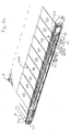
- a section of nine slats 1.1 to 1.9 are shown in the closed position. In their entirety, the slats form 1.1 to 1.9. an area 1 (eg a sloping Roof area). According to a preferred embodiment, the slats are 1.1 to 1.9 Glass. While in Fig. 1a single glass plates are shown, the slats as well well made of insulating glass. This means that the slats are then separated by two formed interconnected glass plates, as it is known from the above The technique is known per se (see, for example, EP 0 568 495 B1, Fig. 2). The slats have typically a length of three to six meters and a width of 30 to 40 Centimeters. Of course, other dimensions can be chosen.
- the slats 1.1 to 1.9 are at appropriate locations by rod-shaped brackets 3.1, 3.2, 3.3 supported from below.
- the brackets 3.1, 3.2 have at their ends z.
- brackets 2.1, 2.2 which surround the slats 1.1, 1.2 on the longitudinal side.
- they are the slats 1.1 to 1.9 over their entire length away with three such brackets held.
- the slats can also be glued to the brackets, so that no encompassing brackets are needed.
- Each bracket 3.1, 3.2 is connected to an operating lever 4.1, 4.2.
- the operating lever 4.1 or 4.2 approximately at 90 degrees to the rod-like Holder 3.1 or 3.2 downwards (that is, approximately at 90 degrees to the surface 1).
- a roller 5.1, 5.2 is provided at the Rear end of the bracket 4.1 or 4.2, that is, where the rear or upper Longitudinal edge of the blade is 1.1 and 1.2, respectively.
- a roller 5.1, 5.2 is provided at the Rear end of the bracket 4.1 or 4.2, that is, where the rear or upper Longitudinal edge of the blade is 1.1 and 1.2, respectively.
- the blade 1.1, 1.2 can be pivoted when opening by Turning the operating lever 4.1 or 4.2.
- the axis of the rollers 5.1, 5.2 each the geometric axis of the pivoting movement.
- the brackets 3.1, 3.2, 3.3 of the successive slats 1.1, 1.2 are connected by a Chain 6 connected together.
- the chain 6 is articulated with each bracket 3.1, 3.2, 3.3 connected.
- In the present example are between the brackets 3.1, 3.2, 3.3 respectively four chain links provided.
- that means in the joint between the second and the third chain link is in each case a roller 7.1, 7.2 to support the chain 6 is provided.
- the chain links give the mutual distance of the slats 1.1 to 1.9 in the closed state before.
- the rollers 5.1, 5.2 and 7.1, 7.2 run preferably on a common (not shown in Fig. 1a) rail (see 15 in Fig. 3).
- FIG. 1a further guide body 8.1, 8.2 can be seen. These are spaced apart, that a depression 9.2 is formed between them. They can be total, that is without Change of mutual distances, to be postponed. The details will be below explained with reference to FIGS 2.
- a chain hoist In order to pull back the slats 1.1 to 1.9, a chain hoist is provided.
- This comprises a drive shaft 10, which the mechanism shown in Fig. 1a coupled with another similar mechanism which is parallel to the present shown mechanism is arranged.
- the fin device typically becomes by two or three mutually spaced and distributed along the length of the slats Mechanisms of the type shown actuated.
- On the drive shaft 10 is seated a gear 11, which drives the chain 12.
- the chain 12 is guided to the bottom slat 1.1 and connected to this. It is self-contained and by the pinion 13.1, 13.2, 13.3 guided in their orbit and deflected. (In Fig. 1a, the lowermost to the pinions 13.2, 13.3 guided part of the chain 12 not shown.)
- the lamellar device shown can be opened as follows (see Figures 1b to 1d): First the lamellae 1.1 to 1.9 are opened synchronously (FIG. 1b). This will be done achieved that the guide body 8.1, 8.2 downward, that is in the direction of the Slat 1.9. be moved to the slat 1.1. Because the position of the rollers 5.1, 5.2 unchanged remains (because of the tension in chains 12 and 6), the operating lever 4.1, 4.2 turned counterclockwise. The rotation of the operating lever 4.1, 4.2 Forcibly leads to a corresponding pivoting movement of the bracket 3.1, 3.2. The Slats 1.1 to 1.9 are thus pivoted synchronously counterclockwise upwards (Fig. 1b).
- the slats 1.1 to 1.9 are open to the maximum, they can move with the chain hoist after be pulled up.
- An unillustrated motor rotates the drive shaft 10 counterclockwise, so that the lowest slat 1.1 is pulled upwards. It will be first the chain links folded, d. H. not articulated joints smooth out laterally (i.e., perpendicular to the chain 12).
- the slat 1.2 remains first still in place. As soon as the slat 1.1 has reached the slat 1.2, the Slat 1.2 taken upwards. This process continues (see Fig. 1c). If the slats are completely retracted, then they line up at the top of the Lamella device close together (Fig. 1d). The mutual distance of Slats 1.1 to 1.9 is in this state only by the thickness of the brackets 3.1, 3.2 certainly.
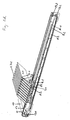
- FIGS. 2 a to 2 c show an enlarged section of the construction in the region of FIG Slats 1.8, 1.9 can be seen. It is the brackets 3.8 and 3.9 with the brackets 2.8 and 2.9 partially shown. It can be seen that the swivel joints for the pivoting movement are formed by rollers 5.8, 5.9. Further, the roles are 7.7, 7.8 to recognize which support the chain 6. The roles 5.8, 5.9. and the rollers 7.7, 7.8 are on the side attached to the chain 6 and run on a guide surface 15 of the carrier profile 14 (see. Fig. 3).
- the guide bodies 8.8, 8.9 are all in one (for example, U-shaped) carrier 16th fixed, which extends substantially over the entire length of the fin device.
- the carrier 16 is displaceably mounted in a guide rail 25, which for Example is attached to the bottom of the carrier profile 14.
- the guide rail 25 has a channel 26 for the chain 12th
- each guide body 8.8 and 8.9 is in each case an end-side guide surface 17.1 or 18.1 and a longitudinal guide surface 17.2. or 18.2 trained.
- the long-side Guide surface 17.2 or 18.2 extends parallel to the linear direction of movement the lamellae 1.8 and 1.9 (ie in the longitudinal direction of the carrier profile 14 (see Fig. 3)
- Front-side guide surface 17.1 and 18.1 may be substantially perpendicular to the longitudinal side Guide surface 17.2 and 18.2 extend.
- the transition between the frontal and the longitudinal guide surface 17.1 or 17.2 can be stepped or rounded be.
- Each guide body 8.8 is associated with a support bracket 19, which is fixed in the Carrier profile 14 is mounted.
- One side of the support bracket 19 is located on the vertical Side wall of the support section 14 and is bolted or welded thereto.
- the other side of the support bracket 19 is perpendicular to the side wall. In the present, the projecting side of the support bracket 19 forms a guide surface 19.1.
- the guide surface 17.2 of the guide body 8.8 and the guide surface 19.1 of Carrier angle 19 are at the same level. You can therefore take turns or at the same time serve as a guide surface for guide rollers.
- the top of the guide body 8.8 is divided into two parts. One half of the top is through the guide surface 17.2 formed and the other half by a recessed down recess 20. In the recess 20 protrudes the projecting side of the support bracket 19 with the Guide surface 19.1.
- the projecting part of the support bracket 19 is not the same width over the entire length, d. H. the guide surface 19.1 does not extend over the entire length in the present example Rather, it ends at the point by the transition is defined between the guide surfaces 17.1 and 17.2.
- the depression, which is formed between the adjacent guide bodies 8.7 and 8.8 is free when the Guide body 8.7, 8.8 are in the position in which the slats are closed (Fig. 2a).
- the remaining part of the projecting side has a recess 21, which the said depression releases.
- the recess 21 is at least so long that the Deepening under the guide surface of the next angular support can disappear, if the carrier 16 is fully extended (in Fig.
- the recess 21 is longer than that between the Guide bodies 8.7 and 8.8 well formed. Likewise, the length of the guide surface 19.1 larger than the length of the recess.
- each operating lever 4.8, 4.9 is a roller 22.8, 22.9 (The rollers 22.4 to 22.9 are shown in Fig. 2c).
- This roller 22.9 for example, rolls on the guide surface 18.1 and 18.2.
- the carrier 16 with the help of Drive rod 26
- the roller 22.9 moves along the guide surface 18.1 from the Recess up against the guide surface 18.2.
- Fig. 2b half open position
- the slats 1.1 until 1.9 are swung up in this way.
- Fig. 2c it can be seen that the members of the chain 6 fold down in a V-shape, when the slats 1.1 to 1.9 stacked in the open position stacked.
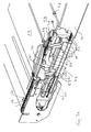
- FIG. 3 shows the schematic external view of a lamination device according to the invention.
- the adjustment mechanisms for opening and retracting the lamellar elements are housed in a carrier profile 14 and not visible from the outside. In more aesthetic Regards, this is very beneficial. In addition, all the adjusting mechanisms and supporting structures protected in the building against weather influences.
- guide bodies held in a carrier at a mutual distance may also be a metal profile or curved to a suitable curve shape Rod used for the pivoting and for the Moving back the slats (or for the rollers at the end of the operating lever) forms.
- Fig. 4. schematically another construction for generating the pivoting movement shown.
- These are two, for example, identically designed guide rails 27, 28, which recesses 29, 30 have at regular intervals. If the Guide rails 27, 28 are positioned relative to each other so that the recesses 29, 30 (perpendicular to the guide rail considered) aligned with each other, then that is the end the operating lever mounted roller in the "lowest" position, d. H. the slats are closed. Now, the guide rails 27, 28 are moved relative to each other, as shown in Fig. 4. Rise, then reduces the free cross-section the depression and the named role is driven out of the deepening, leading to an opening of the slat leads. Are the recesses 29, 30 completely against each other offset, then the role, which is as wide as the two guide rails 27, 28th together, at a constant level.
- the guide rail 27 can, for example, in place of the guide body 8.1, 8.2 occur and the guide rail 28 in place of the support bracket 19th
- the support bracket replaced by a different construction can be. Basically, it's just that the serving to swing up Guide surfaces (namely the end-side guide surfaces 17.1,18.1 out of function can be set when the lamellar elements are retracted. Instead of two relative to each other displaceable and complementary guide rails can also a mechanism be provided with pivotable guide surfaces. That means that Guide surfaces, which are required for swiveling up the slats, are included a suitable mechanical control or a motor drive from a brought ramp-like position in a "flat" position.
- the function of the chain 6 can also be achieved by other means. So are to Example stepped locks or stops conceivable, which in the places of the desired Rest positions of the slats are provided. At the plate carriers can for example, laterally protruding bolts may be formed, which are positioned that they can only be blocked by their respective associated lock. (Each lock is slightly higher than any other lock that is too high up Slats belong. In the same way, the position of the bolt is fixed. So will For example, the bottom slat should only be blocked with the highest lock can, the second-lowest lamella only with the second highest locking etc.)
- the pivot axis of a lamella does not need in the region of the rear longitudinal side of the To be slat. It can also be at a distance to the rear long side (in the direction against the center of the lamella) or even below the middle of the lamella. Conversely, the pivot axis can also be behind the rear longitudinal side of the blade.
- the invention provides a novel lamellar construction has been created, which allows the (usually relatively heavy)
- glass slats can be swiveled and moved without them these two movements are necessarily coupled or synchronized.
Landscapes
- Engineering & Computer Science (AREA)
- Architecture (AREA)
- Civil Engineering (AREA)
- Structural Engineering (AREA)
- Blinds (AREA)
Priority Applications (2)
| Application Number | Priority Date | Filing Date | Title |
|---|---|---|---|
| EP04405034A EP1555379A1 (fr) | 2004-01-19 | 2004-01-19 | Rideau à lammes |
| EP05405029A EP1555380A1 (fr) | 2004-01-19 | 2005-01-19 | Rideau à lammes |
Applications Claiming Priority (1)
| Application Number | Priority Date | Filing Date | Title |
|---|---|---|---|
| EP04405034A EP1555379A1 (fr) | 2004-01-19 | 2004-01-19 | Rideau à lammes |
Publications (1)
| Publication Number | Publication Date |
|---|---|
| EP1555379A1 true EP1555379A1 (fr) | 2005-07-20 |
Family
ID=34610253
Family Applications (1)
| Application Number | Title | Priority Date | Filing Date |
|---|---|---|---|
| EP04405034A Withdrawn EP1555379A1 (fr) | 2004-01-19 | 2004-01-19 | Rideau à lammes |
Country Status (1)
| Country | Link |
|---|---|
| EP (1) | EP1555379A1 (fr) |
Cited By (8)
| Publication number | Priority date | Publication date | Assignee | Title |
|---|---|---|---|---|
| ITVI20110244A1 (it) * | 2011-09-12 | 2013-03-13 | Vitrum Mioni S R L | Struttura composita di protezione e/o riparo per l'installazione inambienti esterni |
| WO2013014303A3 (fr) * | 2011-07-22 | 2013-03-21 | Rivas Fernandez Manuel Bosco | Verrière pliable motorisée |
| FR3012486A1 (fr) * | 2013-10-31 | 2015-05-01 | Soliso Europ | Panneau a lames pour construction legere telle que pergola, abris de jardin ou similaire et construction legere integrant un tel panneau |
| WO2015063433A1 (fr) * | 2013-11-04 | 2015-05-07 | Biossun | Installation pour couvrir et découvrir une surface a l'aide de lames orientables sans espace de rangement dédie |
| WO2017109165A1 (fr) * | 2015-12-23 | 2017-06-29 | Heroal - Johann Henkenjohann Gmbh & Co. Kg | Système de protection solaire |
| EP3613916A3 (fr) * | 2018-08-21 | 2020-04-01 | Gerhard Geiger GmbH & Co. KG | Dispositif pour le positionnement des éléments mobiles d'un système de protection solaire |
| IT201800009330A1 (it) * | 2018-10-10 | 2020-04-10 | Tender Srl | Dispositivo a frangisole con alette orientabili ed apribile |
| EP4345224A1 (fr) | 2022-09-30 | 2024-04-03 | Brianzatende S.r.l. | Structure de couverture |
Citations (4)
| Publication number | Priority date | Publication date | Assignee | Title |
|---|---|---|---|---|
| NL8300949A (nl) * | 1983-03-16 | 1984-10-16 | Guy De Sevaux | Warmte-isolerend zonweringssysteem. |
| DE3500114A1 (de) * | 1985-01-04 | 1986-07-10 | Arthur 8000 München Klemt | Vorrichtung zum befestigen, oeffnen und schliessen von in horizontaler lage schuppenartig quer zur tragekonstruktion angeordneten rahmenlosen mehrscheiben-isolierglaeser o.dgl. |
| DE4020334A1 (de) * | 1990-06-26 | 1992-01-09 | Walter Roesler | Anordnung zum verschwenken lamellenartig angebrachter, ein wand- oder dachelement bildender plattenelemente |
| EP1130210A2 (fr) * | 2000-02-29 | 2001-09-05 | Colt International Holdings Ag | Dispositif de protection solaire |
-
2004
- 2004-01-19 EP EP04405034A patent/EP1555379A1/fr not_active Withdrawn
Patent Citations (4)
| Publication number | Priority date | Publication date | Assignee | Title |
|---|---|---|---|---|
| NL8300949A (nl) * | 1983-03-16 | 1984-10-16 | Guy De Sevaux | Warmte-isolerend zonweringssysteem. |
| DE3500114A1 (de) * | 1985-01-04 | 1986-07-10 | Arthur 8000 München Klemt | Vorrichtung zum befestigen, oeffnen und schliessen von in horizontaler lage schuppenartig quer zur tragekonstruktion angeordneten rahmenlosen mehrscheiben-isolierglaeser o.dgl. |
| DE4020334A1 (de) * | 1990-06-26 | 1992-01-09 | Walter Roesler | Anordnung zum verschwenken lamellenartig angebrachter, ein wand- oder dachelement bildender plattenelemente |
| EP1130210A2 (fr) * | 2000-02-29 | 2001-09-05 | Colt International Holdings Ag | Dispositif de protection solaire |
Cited By (13)
| Publication number | Priority date | Publication date | Assignee | Title |
|---|---|---|---|---|
| WO2013014303A3 (fr) * | 2011-07-22 | 2013-03-21 | Rivas Fernandez Manuel Bosco | Verrière pliable motorisée |
| ES2436219R1 (es) * | 2011-07-22 | 2014-02-11 | Miguel Angel PETIT GOIG | Montera plegable motorizada |
| ITVI20110244A1 (it) * | 2011-09-12 | 2013-03-13 | Vitrum Mioni S R L | Struttura composita di protezione e/o riparo per l'installazione inambienti esterni |
| FR3012486A1 (fr) * | 2013-10-31 | 2015-05-01 | Soliso Europ | Panneau a lames pour construction legere telle que pergola, abris de jardin ou similaire et construction legere integrant un tel panneau |
| EP2868833A1 (fr) * | 2013-10-31 | 2015-05-06 | Soliso Europe | Panneau à lames pour construction légère telle que pergola, abris de jardin ou similaire et construction légère intégrant un tel panneau |
| FR3012840A1 (fr) * | 2013-11-04 | 2015-05-08 | Biossun | Installation pour couvrir et decouvrir une surface a l'aide de lames orientables sans espace de rangement dedie |
| WO2015063433A1 (fr) * | 2013-11-04 | 2015-05-07 | Biossun | Installation pour couvrir et découvrir une surface a l'aide de lames orientables sans espace de rangement dédie |
| WO2017109165A1 (fr) * | 2015-12-23 | 2017-06-29 | Heroal - Johann Henkenjohann Gmbh & Co. Kg | Système de protection solaire |
| EP3613916A3 (fr) * | 2018-08-21 | 2020-04-01 | Gerhard Geiger GmbH & Co. KG | Dispositif pour le positionnement des éléments mobiles d'un système de protection solaire |
| IT201800009330A1 (it) * | 2018-10-10 | 2020-04-10 | Tender Srl | Dispositivo a frangisole con alette orientabili ed apribile |
| WO2020074451A1 (fr) | 2018-10-10 | 2020-04-16 | Tender S.R.L. | Dispositif d'écran solaire pouvant être ouvert avec lattes ajustables |
| US11313131B2 (en) | 2018-10-10 | 2022-04-26 | Tender S.R.L. | Openable sunscreen device with adjustable slats |
| EP4345224A1 (fr) | 2022-09-30 | 2024-04-03 | Brianzatende S.r.l. | Structure de couverture |
Similar Documents
| Publication | Publication Date | Title |
|---|---|---|
| DE202011001556U1 (de) | Faltladenanordnung mit mehreren in sich starren Faltladenelementen mit abwechselnd ausknickenden und nicht ausknickenden Elementkanten | |
| DE202021102781U1 (de) | Abdeckungsvorrichtung | |
| CH634630A5 (en) | Retractable and extendible covering device in the manner of a roller shutter | |
| EP2843149B1 (fr) | Lucarne avec mécanisme d'ouverture | |
| EP1555379A1 (fr) | Rideau à lammes | |
| DE4020334C2 (de) | Wand- oder Dachelement mit einem rahmenartigen Traggestell und verschwenkbar gehalterten, plattenartigen Lamellen | |
| EP1555380A1 (fr) | Rideau à lammes | |
| DE3403920A1 (de) | Jalousie fuer fenster- oder tueroeffnungen von bauwerken | |
| DE3337436C2 (de) | Lamellen-Sonnenschutz | |
| DE102005037775A1 (de) | Jalousierbarer Rollladen | |
| DE102005037756A1 (de) | Rollladen für ein Dachfenster | |
| EP4141192A1 (fr) | Toit à lamelles pourvu de lamelles mobiles et d'entraînement intégré | |
| DE102006027886B3 (de) | Dachschneeräumanlage | |
| EP0383067B1 (fr) | Volet roulant pour ouvertures dans les toitures ou les murs, particulièrement avec une fenêtre de toiture basculante | |
| EP3369882B1 (fr) | Entraînement à chaîne en poussée et station à chaîne | |
| DE4031388A1 (de) | Seitensektionaltor oder rundlauftor, deckensektionaltor | |
| CH630992A5 (en) | Window having a sash which can be tilted and horizontally displaced | |
| DE102014118194A1 (de) | Stellvorrichtung für einen Flügel sowie Vorrichtung zur Einstellung von mehreren Flügeln | |
| EP1798361B1 (fr) | Porte | |
| DE2756475A1 (de) | Schattierungseinrichtung fuer ein gewaechshaus | |
| EP4141191B1 (fr) | Toit à lamelles pourvu de lamelles mobiles à entraînement par courroie | |
| EP1388637B1 (fr) | Rouleau | |
| EP1225286B1 (fr) | Couverture extensible pour véranda | |
| DE3408177C1 (de) | Rolladenjalousie | |
| DE2417863A1 (de) | Schwimmbecken-faltabdeckung |
Legal Events
| Date | Code | Title | Description |
|---|---|---|---|
| PUAI | Public reference made under article 153(3) epc to a published international application that has entered the european phase |
Free format text: ORIGINAL CODE: 0009012 |
|
| AK | Designated contracting states |
Kind code of ref document: A1 Designated state(s): AT BE BG CH CY CZ DE DK EE ES FI FR GB GR HU IE IT LI LU MC NL PT RO SE SI SK TR |
|
| AX | Request for extension of the european patent |
Extension state: AL LT LV MK |
|
| AKX | Designation fees paid | ||
| REG | Reference to a national code |
Ref country code: DE Ref legal event code: 8566 |
|
| STAA | Information on the status of an ep patent application or granted ep patent |
Free format text: STATUS: THE APPLICATION IS DEEMED TO BE WITHDRAWN |
|
| 18D | Application deemed to be withdrawn |
Effective date: 20060121 |