EP1555379A1 - Louvre with lamella - Google Patents
Louvre with lamella Download PDFInfo
- Publication number
- EP1555379A1 EP1555379A1 EP04405034A EP04405034A EP1555379A1 EP 1555379 A1 EP1555379 A1 EP 1555379A1 EP 04405034 A EP04405034 A EP 04405034A EP 04405034 A EP04405034 A EP 04405034A EP 1555379 A1 EP1555379 A1 EP 1555379A1
- Authority
- EP
- European Patent Office
- Prior art keywords
- slats
- slat
- guide
- guide surface
- sliding movement
- Prior art date
- Legal status (The legal status is an assumption and is not a legal conclusion. Google has not performed a legal analysis and makes no representation as to the accuracy of the status listed.)
- Withdrawn
Links
Images


Classifications
-
- E—FIXED CONSTRUCTIONS
- E04—BUILDING
- E04F—FINISHING WORK ON BUILDINGS, e.g. STAIRS, FLOORS
- E04F10/00—Sunshades, e.g. Florentine blinds or jalousies; Outside screens; Awnings or baldachins
- E04F10/08—Sunshades, e.g. Florentine blinds or jalousies; Outside screens; Awnings or baldachins of a plurality of similar rigid parts, e.g. slabs, lamellae
- E04F10/10—Sunshades, e.g. Florentine blinds or jalousies; Outside screens; Awnings or baldachins of a plurality of similar rigid parts, e.g. slabs, lamellae collapsible or extensible; metallic Florentine blinds; awnings with movable parts such as louvres
-
- E—FIXED CONSTRUCTIONS
- E06—DOORS, WINDOWS, SHUTTERS, OR ROLLER BLINDS IN GENERAL; LADDERS
- E06B—FIXED OR MOVABLE CLOSURES FOR OPENINGS IN BUILDINGS, VEHICLES, FENCES OR LIKE ENCLOSURES IN GENERAL, e.g. DOORS, WINDOWS, BLINDS, GATES
- E06B7/00—Special arrangements or measures in connection with doors or windows
- E06B7/02—Special arrangements or measures in connection with doors or windows for providing ventilation, e.g. through double windows; Arrangement of ventilation roses
- E06B7/08—Louvre doors, windows or grilles
Definitions
- the invention relates to a slat device with a plurality of slats, in particular of Glass, for opening, in particular, as a roof or wall of a building serving surface, in which the slats from an inside of the building ago are held and wherein at least one blade is mounted so that they have a Pivoting movement out of the surface and a sliding movement along the Can perform surface.
- each lamella is individual and Stored pivotally mounted, wherein the various pivot mechanisms via a coupled common drive, so that all slats are opened together can (DE 35 00 114 C1, CH 686 633, DE 41 02 922 C1, DE 4227278 C2, EP 0 568 495 B1, DE 196 45 802 C1, DE 101 23 565 C1).
- the other type is the Slats attached to a scissors mechanism, which the slats simultaneously pivots and retracts so that a completely free opening can be formed (DE 40 20 334 C2).
- the lamella glazing of the former type is particularly suitable for normally inhabited and isolated buildings.
- the advantage of the individual swivel mechanism is namely, that the slats are opened slightly in a pitched roof without the risk of water entering during a sudden rain fall.
- the blades guided by a scissor mechanism have the Advantage that the roof can be completely withdrawn in fine weather, so that the user can sit in the open air. (Further, with such Scissors mechanism also glass doors or glass fronts are formed.) It is however It is not possible to open the slats halfway without simultaneously pulling the roof halfway becomes.
- the object of the invention is a belonging to the aforementioned technical field Lamella device to create, which allows on the one hand the slats panning without being withdrawn at the same time, on the other hand, retract the blades to release the opening.
- the lamellar device which is a surface associated with the device closes, at least one, but typically several slats.
- the slats are held from an inside of the building (and not at the narrow ends the lamellae, as would be common, for example, with metal gates).
- At least one lamella is mounted so that they pivot out of said surface and can perform a sliding movement along the surface.
- the roof can be opened slightly without the slats retracted at the same time Need to become.
- the conservatory is thus ventilated and at the same time covered (eg protected against sudden rain).
- the conservatory can be in an above open patio.
- At least one louver is pivotable stored a sliding plate carrier.
- the pivotable mounting of the slat on the disk carrier forms (together with the pivot drive) the one adjusting mechanism and the slidable mounting of the disk carrier on a linear Guide surface (together with a linear drive) the other adjustment mechanism.
- the plate carriers of the different lamellae can be completely independent of each other be. It is therefore conceivable that the structural design of the linear adjustment mechanism such is that a single (or each individual) plate carrier individually and is independent of the others. In contrast, can also be provided be that two or more plate carrier are coupled in motion, so that they can be moved (shifted) synchronously or successively to each other.
- the blade is first swung open and then moved.
- the Pivoting motion geometrically represents a rotation about a geometric one Axis.
- This geometric axis is usually not in the area, which is defined by the glass fins as a whole, but at a distance to this level.
- the adjusting mechanism for the pivoting movement comprises z. B. a roller guide system for a lever element connected to the lamella. So the lever element has a roller which is guided on a guide track of the roller guide system. By the interaction of the roller with the guide track or guide curve of the roller guide system the pivoting movement is controlled or generated.
- the roller guide or a part thereof may be displaceable relative to the pivot axis of the slat.
- roller guide instead of the roller guide and a slide guide can be used.
- a slide guide can, for example be realized in that bolts are guided in a guide slot.
- Adjustment mechanism for the pivoting movement may also have a servo motor.
- the pivoting movement is associated by one of the lamella Server engine turned. Although this brings an increased mechanical or electrical Effort with it, but allows a freer control of slats movement.
- the guide means for controlling the movement of the Slats can be designed so that the slats in each pivot position a have a clearly defined position (forced operation). This way you can be sure be that the slats can not "flutter” when they are from a sudden gust of wind be recorded. In many cases, however, the weight of the glass lamella be sufficiently large, so that a "one-sided" leadership (i.e., a support surface for the Guide rollers) provides sufficient security, against unwanted movements.
- the adjustment mechanism for the displacement of the slats preferably comprises a flexible coupling mechanism z.
- the coupling mechanism gives the maximum distance of the slats to each other.
- the flexibility of the coupling mechanism makes it possible to bring the slats close to each other during retraction.
- each displaceable plate carrier an independent linear drive (For example, a gear drive), which is electronically controlled on a certain position can be brought.
- the Linear drive comprises a drive spindle which extends over the entire length of the linear movement the lamellae extends, and that each lamella is a coupling mechanism is assigned, which in each case at a certain, controlled time to the Coupling drive spindle and causes the take away of the lamella.
- Drive spindle can also be provided a rope or a chain on which the Can engage and disengage the disk carrier.
- a cable or chain hoist can be provided be, which engages the lowest lamellar element and this pulls upwards.
- the drive motor can be accommodated above.
- Preferably is with worked an endless chain hoist.
- the lowermost plate element can be coupled with a spindle drive.
- the lamellar element can then be transported upwards by means of the threaded spindle be, with the remaining lamellar elements are collected in order.
- the Threaded spindle can absorb relatively high tensile forces.
- the roller guide system for generating the pivoting movement may, for example, each lamella form a guideway having a recess.
- each lamella attached roll is guided into the depression, then the Slat brought into the closed position.
- To the depression closes a relative to it elevated guideway, which causes the slat in the open position linear can be moved. In this way, with relatively little mechanical Expense the desired pivoting movement can be achieved.
- the elevated portion of the guideway or that portion, the linear guide serves may be divided into two parts in the longitudinal direction.
- a first part as stationary Rail and a second part designed as a sliding body.
- the movable one Body is movable relative to the fixed rail. Between the bodies are the next provided above recesses. If the bodies are moved, then the roles of adjusting mechanism for the pivoting movement of the wells driven out.
- the depressions disappear behind or below the fixed ones Rails, so that the lamellar elements on the elevated guideway (and thus in the open pivot position) can be moved linearly.
- the bodies are for example Fixed on a continuous support rail at regular intervals.
- the slats are provided with support arms held, which surround the longitudinal sides of the slats with brackets.
- the hollow profiles For example, square profiles with a longitudinal slot at the top.
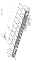
- a section of nine slats 1.1 to 1.9 are shown in the closed position. In their entirety, the slats form 1.1 to 1.9. an area 1 (eg a sloping Roof area). According to a preferred embodiment, the slats are 1.1 to 1.9 Glass. While in Fig. 1a single glass plates are shown, the slats as well well made of insulating glass. This means that the slats are then separated by two formed interconnected glass plates, as it is known from the above The technique is known per se (see, for example, EP 0 568 495 B1, Fig. 2). The slats have typically a length of three to six meters and a width of 30 to 40 Centimeters. Of course, other dimensions can be chosen.
- the slats 1.1 to 1.9 are at appropriate locations by rod-shaped brackets 3.1, 3.2, 3.3 supported from below.
- the brackets 3.1, 3.2 have at their ends z.
- brackets 2.1, 2.2 which surround the slats 1.1, 1.2 on the longitudinal side.
- they are the slats 1.1 to 1.9 over their entire length away with three such brackets held.
- the slats can also be glued to the brackets, so that no encompassing brackets are needed.
- Each bracket 3.1, 3.2 is connected to an operating lever 4.1, 4.2.
- the operating lever 4.1 or 4.2 approximately at 90 degrees to the rod-like Holder 3.1 or 3.2 downwards (that is, approximately at 90 degrees to the surface 1).
- a roller 5.1, 5.2 is provided at the Rear end of the bracket 4.1 or 4.2, that is, where the rear or upper Longitudinal edge of the blade is 1.1 and 1.2, respectively.
- a roller 5.1, 5.2 is provided at the Rear end of the bracket 4.1 or 4.2, that is, where the rear or upper Longitudinal edge of the blade is 1.1 and 1.2, respectively.
- the blade 1.1, 1.2 can be pivoted when opening by Turning the operating lever 4.1 or 4.2.
- the axis of the rollers 5.1, 5.2 each the geometric axis of the pivoting movement.
- the brackets 3.1, 3.2, 3.3 of the successive slats 1.1, 1.2 are connected by a Chain 6 connected together.
- the chain 6 is articulated with each bracket 3.1, 3.2, 3.3 connected.
- In the present example are between the brackets 3.1, 3.2, 3.3 respectively four chain links provided.
- that means in the joint between the second and the third chain link is in each case a roller 7.1, 7.2 to support the chain 6 is provided.
- the chain links give the mutual distance of the slats 1.1 to 1.9 in the closed state before.
- the rollers 5.1, 5.2 and 7.1, 7.2 run preferably on a common (not shown in Fig. 1a) rail (see 15 in Fig. 3).
- FIG. 1a further guide body 8.1, 8.2 can be seen. These are spaced apart, that a depression 9.2 is formed between them. They can be total, that is without Change of mutual distances, to be postponed. The details will be below explained with reference to FIGS 2.
- a chain hoist In order to pull back the slats 1.1 to 1.9, a chain hoist is provided.
- This comprises a drive shaft 10, which the mechanism shown in Fig. 1a coupled with another similar mechanism which is parallel to the present shown mechanism is arranged.
- the fin device typically becomes by two or three mutually spaced and distributed along the length of the slats Mechanisms of the type shown actuated.
- On the drive shaft 10 is seated a gear 11, which drives the chain 12.
- the chain 12 is guided to the bottom slat 1.1 and connected to this. It is self-contained and by the pinion 13.1, 13.2, 13.3 guided in their orbit and deflected. (In Fig. 1a, the lowermost to the pinions 13.2, 13.3 guided part of the chain 12 not shown.)
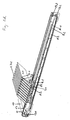
- the lamellar device shown can be opened as follows (see Figures 1b to 1d): First the lamellae 1.1 to 1.9 are opened synchronously (FIG. 1b). This will be done achieved that the guide body 8.1, 8.2 downward, that is in the direction of the Slat 1.9. be moved to the slat 1.1. Because the position of the rollers 5.1, 5.2 unchanged remains (because of the tension in chains 12 and 6), the operating lever 4.1, 4.2 turned counterclockwise. The rotation of the operating lever 4.1, 4.2 Forcibly leads to a corresponding pivoting movement of the bracket 3.1, 3.2. The Slats 1.1 to 1.9 are thus pivoted synchronously counterclockwise upwards (Fig. 1b).
- the slats 1.1 to 1.9 are open to the maximum, they can move with the chain hoist after be pulled up.
- An unillustrated motor rotates the drive shaft 10 counterclockwise, so that the lowest slat 1.1 is pulled upwards. It will be first the chain links folded, d. H. not articulated joints smooth out laterally (i.e., perpendicular to the chain 12).
- the slat 1.2 remains first still in place. As soon as the slat 1.1 has reached the slat 1.2, the Slat 1.2 taken upwards. This process continues (see Fig. 1c). If the slats are completely retracted, then they line up at the top of the Lamella device close together (Fig. 1d). The mutual distance of Slats 1.1 to 1.9 is in this state only by the thickness of the brackets 3.1, 3.2 certainly.
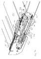
- FIGS. 2 a to 2 c show an enlarged section of the construction in the region of FIG Slats 1.8, 1.9 can be seen. It is the brackets 3.8 and 3.9 with the brackets 2.8 and 2.9 partially shown. It can be seen that the swivel joints for the pivoting movement are formed by rollers 5.8, 5.9. Further, the roles are 7.7, 7.8 to recognize which support the chain 6. The roles 5.8, 5.9. and the rollers 7.7, 7.8 are on the side attached to the chain 6 and run on a guide surface 15 of the carrier profile 14 (see. Fig. 3).
- the guide bodies 8.8, 8.9 are all in one (for example, U-shaped) carrier 16th fixed, which extends substantially over the entire length of the fin device.
- the carrier 16 is displaceably mounted in a guide rail 25, which for Example is attached to the bottom of the carrier profile 14.
- the guide rail 25 has a channel 26 for the chain 12th
- each guide body 8.8 and 8.9 is in each case an end-side guide surface 17.1 or 18.1 and a longitudinal guide surface 17.2. or 18.2 trained.
- the long-side Guide surface 17.2 or 18.2 extends parallel to the linear direction of movement the lamellae 1.8 and 1.9 (ie in the longitudinal direction of the carrier profile 14 (see Fig. 3)
- Front-side guide surface 17.1 and 18.1 may be substantially perpendicular to the longitudinal side Guide surface 17.2 and 18.2 extend.
- the transition between the frontal and the longitudinal guide surface 17.1 or 17.2 can be stepped or rounded be.
- Each guide body 8.8 is associated with a support bracket 19, which is fixed in the Carrier profile 14 is mounted.
- One side of the support bracket 19 is located on the vertical Side wall of the support section 14 and is bolted or welded thereto.
- the other side of the support bracket 19 is perpendicular to the side wall. In the present, the projecting side of the support bracket 19 forms a guide surface 19.1.
- the guide surface 17.2 of the guide body 8.8 and the guide surface 19.1 of Carrier angle 19 are at the same level. You can therefore take turns or at the same time serve as a guide surface for guide rollers.
- the top of the guide body 8.8 is divided into two parts. One half of the top is through the guide surface 17.2 formed and the other half by a recessed down recess 20. In the recess 20 protrudes the projecting side of the support bracket 19 with the Guide surface 19.1.
- the projecting part of the support bracket 19 is not the same width over the entire length, d. H. the guide surface 19.1 does not extend over the entire length in the present example Rather, it ends at the point by the transition is defined between the guide surfaces 17.1 and 17.2.
- the depression, which is formed between the adjacent guide bodies 8.7 and 8.8 is free when the Guide body 8.7, 8.8 are in the position in which the slats are closed (Fig. 2a).
- the remaining part of the projecting side has a recess 21, which the said depression releases.
- the recess 21 is at least so long that the Deepening under the guide surface of the next angular support can disappear, if the carrier 16 is fully extended (in Fig.
- the recess 21 is longer than that between the Guide bodies 8.7 and 8.8 well formed. Likewise, the length of the guide surface 19.1 larger than the length of the recess.
- each operating lever 4.8, 4.9 is a roller 22.8, 22.9 (The rollers 22.4 to 22.9 are shown in Fig. 2c).
- This roller 22.9 for example, rolls on the guide surface 18.1 and 18.2.
- the carrier 16 with the help of Drive rod 26
- the roller 22.9 moves along the guide surface 18.1 from the Recess up against the guide surface 18.2.
- Fig. 2b half open position
- the slats 1.1 until 1.9 are swung up in this way.
- Fig. 2c it can be seen that the members of the chain 6 fold down in a V-shape, when the slats 1.1 to 1.9 stacked in the open position stacked.
- FIG. 3 shows the schematic external view of a lamination device according to the invention.
- the adjustment mechanisms for opening and retracting the lamellar elements are housed in a carrier profile 14 and not visible from the outside. In more aesthetic Regards, this is very beneficial. In addition, all the adjusting mechanisms and supporting structures protected in the building against weather influences.
- guide bodies held in a carrier at a mutual distance may also be a metal profile or curved to a suitable curve shape Rod used for the pivoting and for the Moving back the slats (or for the rollers at the end of the operating lever) forms.
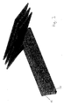
- Fig. 4. schematically another construction for generating the pivoting movement shown.
- These are two, for example, identically designed guide rails 27, 28, which recesses 29, 30 have at regular intervals. If the Guide rails 27, 28 are positioned relative to each other so that the recesses 29, 30 (perpendicular to the guide rail considered) aligned with each other, then that is the end the operating lever mounted roller in the "lowest" position, d. H. the slats are closed. Now, the guide rails 27, 28 are moved relative to each other, as shown in Fig. 4. Rise, then reduces the free cross-section the depression and the named role is driven out of the deepening, leading to an opening of the slat leads. Are the recesses 29, 30 completely against each other offset, then the role, which is as wide as the two guide rails 27, 28th together, at a constant level.
- the guide rail 27 can, for example, in place of the guide body 8.1, 8.2 occur and the guide rail 28 in place of the support bracket 19th
- the support bracket replaced by a different construction can be. Basically, it's just that the serving to swing up Guide surfaces (namely the end-side guide surfaces 17.1,18.1 out of function can be set when the lamellar elements are retracted. Instead of two relative to each other displaceable and complementary guide rails can also a mechanism be provided with pivotable guide surfaces. That means that Guide surfaces, which are required for swiveling up the slats, are included a suitable mechanical control or a motor drive from a brought ramp-like position in a "flat" position.
- the function of the chain 6 can also be achieved by other means. So are to Example stepped locks or stops conceivable, which in the places of the desired Rest positions of the slats are provided. At the plate carriers can for example, laterally protruding bolts may be formed, which are positioned that they can only be blocked by their respective associated lock. (Each lock is slightly higher than any other lock that is too high up Slats belong. In the same way, the position of the bolt is fixed. So will For example, the bottom slat should only be blocked with the highest lock can, the second-lowest lamella only with the second highest locking etc.)
- the pivot axis of a lamella does not need in the region of the rear longitudinal side of the To be slat. It can also be at a distance to the rear long side (in the direction against the center of the lamella) or even below the middle of the lamella. Conversely, the pivot axis can also be behind the rear longitudinal side of the blade.
- the invention provides a novel lamellar construction has been created, which allows the (usually relatively heavy)
- glass slats can be swiveled and moved without them these two movements are necessarily coupled or synchronized.
Landscapes
- Engineering & Computer Science (AREA)
- Architecture (AREA)
- Civil Engineering (AREA)
- Structural Engineering (AREA)
- Blinds (AREA)
Abstract
Description
Die Erfindung betrifft eine Lamellenvorrichtung mit mehreren Lamellen, insbesondere aus Glas, zum öffenbaren Verschliessen einer insbesondere als Dach oder Wand eines Gebäudes dienenden Fläche, bei welcher die Lamellen von einer Innenseite des Gebäudes her gehalten sind und wobei mindestens eine Lamelle derart gelagert ist, dass sie eine Schwenkbewegung aus der Fläche heraus und eine Verschiebebewegung entlang der Fläche ausführen kann. The invention relates to a slat device with a plurality of slats, in particular of Glass, for opening, in particular, as a roof or wall of a building serving surface, in which the slats from an inside of the building ago are held and wherein at least one blade is mounted so that they have a Pivoting movement out of the surface and a sliding movement along the Can perform surface.
Glas geniesst in der Architektur seit vielen Jahren eine grosse Beliebtheit. Bei Glasdächern stellt sich dabei die Frage der geeigneten Belüftung. Es wurden deshalb Lamellen-Fenster entwickelt, welche einen filigranen Aufbau haben und motorisch geöffnet werden können. Die Lamellen sind dabei von der Gebäudeinnenseite her gehalten. Auf diese Weise sind die Stützkonstruktion und die Bewegungsmechanik geschützt (was zum Beispiel bei einer seitlichen Halterung nicht gewährleistet wäre). Im Prinzip kann man zwei Typen von Lamellenverglasungen unterscheiden. Beim ersten Typ ist jede Lamelle individuell und ortsfest schwenkbar gelagert, wobei die verschiedenen Schwenkmechanismen über einen gemeinsamen Antrieb gekoppelt sind, so dass alle Lamellen gemeinsam geöffnet werden können (DE 35 00 114 C1, CH 686 633, DE 41 02 922 C1, DE 4227278 C2, EP 0 568 495 B1, DE 196 45 802 C1, DE 101 23 565 C1). Beim anderen Typ sind die Lamellen an einem Scherenmechanismus angebracht, welcher die Lamellen gleichzeitig schwenkt und zurückzieht, so dass eine vollständig freie Öffnung gebildet werden kann (DE 40 20 334 C2).Glass has enjoyed great popularity in architecture for many years. For glass roofs raises the question of suitable ventilation. It was therefore slat window developed, which have a filigree structure and can be opened by motor. The slats are held by the building inside. In this way, the Support structure and the movement mechanics protected (which, for example, at a lateral bracket would not be guaranteed). In principle, you can use two types of Distinguish lamella glazing. In the first type each lamella is individual and Stored pivotally mounted, wherein the various pivot mechanisms via a coupled common drive, so that all slats are opened together can (DE 35 00 114 C1, CH 686 633, DE 41 02 922 C1, DE 4227278 C2, EP 0 568 495 B1, DE 196 45 802 C1, DE 101 23 565 C1). The other type is the Slats attached to a scissors mechanism, which the slats simultaneously pivots and retracts so that a completely free opening can be formed (DE 40 20 334 C2).
Die Lamellenverglasung der erstgenannten Art eignet sich insbesondere für normal bewohnte und isolierte Bauten. Der Vorteil des individuellen Schwenkmechanismus besteht nämlich darin, dass bei einem Schrägdach die Lamellen geringfügig geöffnet werden können, ohne dass die Gefahr besteht, dass bei einem plötzlichen Regen Wasser eindringt.The lamella glazing of the former type is particularly suitable for normally inhabited and isolated buildings. The advantage of the individual swivel mechanism is namely, that the slats are opened slightly in a pitched roof without the risk of water entering during a sudden rain fall.
Demgegenüber haben die von einem Scherenmechanismus geführten Lamellen den Vorteil, dass das Dach bei schönem Wetter vollständig zurückgezogen werden kann, so dass der Benutzer unter freiem Himmel sitzen kann. (Ferner können mit einem solchen Scherenmechanismus auch Glastüren bzw. Glasfronten gebildet werden.) Es ist jedoch nicht möglich, die Lamellen halb zu öffnen, ohne dass gleichzeitig das Dach halb zurückgezogen wird. In contrast, the blades guided by a scissor mechanism have the Advantage that the roof can be completely withdrawn in fine weather, so that the user can sit in the open air. (Further, with such Scissors mechanism also glass doors or glass fronts are formed.) It is however It is not possible to open the slats halfway without simultaneously pulling the roof halfway becomes.
Aufgabe der Erfindung ist es, eine dem eingangs genannten technischen Gebiet zugehörende Lamellenvorrichtung zu schaffen, welche es erlaubt, einerseits die Lamellen zu schwenken, ohne dass sie gleichzeitig zurückgezogen werden, und es andererseits ermöglicht, die Lamellen zurückzuziehen, um die Öffnung freizugeben.The object of the invention is a belonging to the aforementioned technical field Lamella device to create, which allows on the one hand the slats panning without being withdrawn at the same time, on the other hand, retract the blades to release the opening.
Die Lösung der Aufgabe ist durch die Merkmale des Anspruchs 1 definiert. Gemäss der
Erfindung hat die Lamellenvorrichtung, welche eine der Vorrichtung zugeordnete Fläche
verschliesst, mindestens eine, typischerweise aber mehrere Lamellen. Die Lamellen sind
von einer Innenseite des Gebäudes her gehalten (und nicht an den schmalseitigen Enden
der Lamellen, wie es zum Beispiel bei Metallstoren üblich wäre). Mindestens eine Lamelle
ist so gelagert, dass sie eine Schwenkbewegung aus der genannten Fläche heraus und
eine Verschiebebewegung entlang der Fläche ausführen kann. Es sind zwei Verstellmechanismen
vorgesehen. Der eine davon steuert die Schwenkbewegung der Lamellen,
ohne dass gleichzeitig eine Verschiebebewegung bewirkt wird. Der andere Verstellmechanismus
steuert die Verschiebebewegung, ohne dass gleichzeitig eine Schwenkbewegung
bewirkt wird.The solution of the problem is defined by the features of
Mit der Erfindung ist es möglich, die Vorteile der beiden eingangs genannten Typen von Lamellenfenstern zu kombinieren. So kann zum Beispiel bei einem Glashaus-Wintergarten das Dach geringfügig geöffnet werden, ohne dass die Lamellen gleichzeitig zurückgezogen werden müssen. Der Wintergarten ist damit belüftet und gleichzeitig bedeckt (z. B. geschützt gegen plötzlichen Regen). Andererseits kann der Wintergarten in einen oben offenen Gartensitzplatz verwandelt werden.With the invention, it is possible to take advantage of the two types mentioned above Combine louvre windows. For example, at a glass house conservatory the roof can be opened slightly without the slats retracted at the same time Need to become. The conservatory is thus ventilated and at the same time covered (eg protected against sudden rain). On the other hand, the conservatory can be in an above open patio.
Gemäss einer bevorzugten Ausführungsform ist mindestens eine Lamelle schwenkbar auf einem verschiebbaren Lamellenträger gelagert. Die schwenkbare Lagerung der Lamelle auf dem Lamellenträger bildet dabei (zusammen mit dem Schwenkantrieb) den einen Verstellmechanismus und die verschiebbare Lagerung des Lamellenträgers auf einer linearen Führungsfläche (zusammen mit einem linearen Antrieb) den anderen Verstellmechanismus. Die Lamellenträger der verschiedenen Lamellen können völlig unabhängig voneinander sein. Es ist also denkbar, dass die konstruktive Ausführung des linearen Verstellmechanismus derart ist, dass ein einzelner (oder jeder einzelne) Lamellenträger individuell und unabhängig von den anderen verschiebbar ist. Demgegenüber kann auch vorgesehen sein, dass zwei oder mehrere Lamellenträger bewegungsmässig gekoppelt sind, so dass sie synchron oder sukzessive zueinander bewegt (verschoben) werden können.According to a preferred embodiment, at least one louver is pivotable stored a sliding plate carrier. The pivotable mounting of the slat on the disk carrier forms (together with the pivot drive) the one adjusting mechanism and the slidable mounting of the disk carrier on a linear Guide surface (together with a linear drive) the other adjustment mechanism. The plate carriers of the different lamellae can be completely independent of each other be. It is therefore conceivable that the structural design of the linear adjustment mechanism such is that a single (or each individual) plate carrier individually and is independent of the others. In contrast, can also be provided be that two or more plate carrier are coupled in motion, so that they can be moved (shifted) synchronously or successively to each other.
Typischerweise wird die Lamelle zunächst aufgeschwenkt und erst dann verschoben. Die Schwenkbewegung stellt in geometrischer Hinsicht eine Drehung um eine geometrische Achse dar. Diese geometrische Achse befindet sich in aller Regel nicht in der Fläche, welche durch die Glaslamellen insgesamt definiert wird, sondern in einem Abstand zu dieser Ebene.Typically, the blade is first swung open and then moved. The Pivoting motion geometrically represents a rotation about a geometric one Axis. This geometric axis is usually not in the area, which is defined by the glass fins as a whole, but at a distance to this level.
Der Verstellmechanismus für die Schwenkbewegung umfasst z. B. ein Rollenführungssystem für ein mit der Lamelle verbundenes Hebelelement. Das Hebelelement hat also eine Rolle, welche auf einer Führungsbahn des Rollenführungssystems geführt ist. Durch das Zusammenwirken der Rolle mit der Führungsbahn bzw. Führungskurve des Rollenführungssystems wird die Schwenkbewegung gesteuert bzw. erzeugt. Die Rollenführung oder ein Teil derselben kann relativ zur Schwenkachse der Lamelle verschiebbar sein.The adjusting mechanism for the pivoting movement comprises z. B. a roller guide system for a lever element connected to the lamella. So the lever element has a roller which is guided on a guide track of the roller guide system. By the interaction of the roller with the guide track or guide curve of the roller guide system the pivoting movement is controlled or generated. The roller guide or a part thereof may be displaceable relative to the pivot axis of the slat.
An Stelle der Rollenführung kann auch eine Schlittenführung eingesetzt werden. Das heisst, es sind keine drehbaren Teile (Rollen) nötig. Eine Schlittenführung kann zum Beispiel dadurch realisiert werden, dass Bolzen in einem Führungsschlitz geführt werden. Der Verstellmechanismus für die Schwenkbewegung kann auch einen Servomotor aufweisen. Bei dieser Ausführungsform wird die Schwenkbewegung durch einen der Lamelle zugeordneten Servermotor gedreht. Dies bringt zwar einen erhöhten mechanischen bzw. elektrischen Aufwand mit sich, erlaubt aber eine freiere Steuerung der Lamellenbewegung.Instead of the roller guide and a slide guide can be used. The means, there are no rotatable parts (rollers) necessary. A slide guide can, for example be realized in that bolts are guided in a guide slot. Of the Adjustment mechanism for the pivoting movement may also have a servo motor. In this embodiment, the pivoting movement is associated by one of the lamella Server engine turned. Although this brings an increased mechanical or electrical Effort with it, but allows a freer control of slats movement.
Die Führungsmittel (Schiene, Rollen, Schlitten etc.) zur Steuerung der Bewegung der Lamellen können so ausgebildet sein, dass die Lamellen in jeder Schwenkposition eine eindeutig definierte Lage haben (Zwangsführung). Auf diese Weise kann sichergestellt werden, dass die Lamellen nicht "flattern" können, wenn sie von einem plötzlichen Windstoss erfasst werden. In vielen Fällen wird jedoch das Eigengewicht der Glaslamelle genügend gross sein, so dass eine "einseitige" Führung (d.h. eine Auflagefläche für die Führungsrollen) ausreichend Sicherheit bietet, gegen unerwünschte Bewegungen.The guide means (rail, rollers, carriages, etc.) for controlling the movement of the Slats can be designed so that the slats in each pivot position a have a clearly defined position (forced operation). This way you can be sure be that the slats can not "flutter" when they are from a sudden gust of wind be recorded. In many cases, however, the weight of the glass lamella be sufficiently large, so that a "one-sided" leadership (i.e., a support surface for the Guide rollers) provides sufficient security, against unwanted movements.
Der Verstellmechanismus für die Verschiebung der Lamellen umfasst vorzugsweise einen flexiblen Koppelmechanismus z. B. eine Kette oder ein Seil. Der Koppelmechanismus gibt den maximalen Abstand der Lamellen zueinander vor. Die Flexibilität des Koppelmechanismus ermöglicht es, die Lamellen beim Zurückziehen nahe nebeneinander zu bringen.The adjustment mechanism for the displacement of the slats preferably comprises a flexible coupling mechanism z. As a chain or a rope. The coupling mechanism gives the maximum distance of the slats to each other. The flexibility of the coupling mechanism makes it possible to bring the slats close to each other during retraction.
Es ist auch denkbar, dass jeder verschiebbare Lamellenträger einen eigenständigen Linearantrieb (z. B. einen Zahnradantrieb) aufweist, welcher elektronisch gesteuert auf eine bestimmte Position gebracht werden kann. Eine weitere Variante besteht darin, dass der Linearantrieb eine Antriebsspindel umfasst, welche sich über die ganze Länge der Linearbewegung der Lamellen erstreckt, und dass jeder Lamelle ein Kupplungsmechanismus zugeordnet ist, welcher sich jeweils zu einem bestimmten, gesteuerten Zeitpunkt an die Antriebsspindel ankoppeln kann und das Mitnehmen der Lamelle bewirkt. An Stelle der Antriebsspindel kann auch ein Seil oder eine Kette vorgesehen sein, an welchem sich der Lamellenträger ein und auskoppeln kann.It is also conceivable that each displaceable plate carrier an independent linear drive (For example, a gear drive), which is electronically controlled on a certain position can be brought. Another variant is that the Linear drive comprises a drive spindle which extends over the entire length of the linear movement the lamellae extends, and that each lamella is a coupling mechanism is assigned, which in each case at a certain, controlled time to the Coupling drive spindle and causes the take away of the lamella. Instead of Drive spindle can also be provided a rope or a chain on which the Can engage and disengage the disk carrier.
Um die Lamellenelemente linear zu verschieben, kann ein Seil- oder Kettenzug vorgesehen sein, welcher am untersten Lamellenelement angreift und dieses nach oben zieht. Bei dieser Anordnung kann der Antriebsmotor oben untergebracht sein. Vorzugsweise wird mit einem endlosen Kettenzug gearbeitet.To move the lamellar elements linearly, a cable or chain hoist can be provided be, which engages the lowest lamellar element and this pulls upwards. at This arrangement, the drive motor can be accommodated above. Preferably is with worked an endless chain hoist.
Alternativ ist es möglich, das unterste Lamellenelement mit einem Spindeltrieb zu koppeln. Das Lamellenelement kann dann mit Hilfe der Gewindespindel nach oben transportiert werden, wobei die übrigen Lamellenelemente der Reihe nach eingesammelt werden. Die Gewindespindel kann relativ hohe Zugkräfte aufnehmen.Alternatively, it is possible to couple the lowermost plate element with a spindle drive. The lamellar element can then be transported upwards by means of the threaded spindle be, with the remaining lamellar elements are collected in order. The Threaded spindle can absorb relatively high tensile forces.
Das Rollenführungssystem zum Erzeugen der Schwenkbewegung kann zum Beispiel für jede Lamelle eine Führungsbahn bilden, die eine Vertiefung aufweist. Wenn die am Hebelelement der Lamelle angebrachte Rolle in die Vertiefung geführt wird, dann wird die Lamelle in die Schliessstellung gebracht. An die Vertiefung schliesst eine relativ dazu erhöhte Führungsbahn an, welche bewirkt, dass die Lamelle in geöffneter Stellung linear verschoben werden kann. Auf diese Weise kann mit verhältnismässig geringem mechanischem Aufwand die erwünschte Schwenkbewegung erreicht werden.The roller guide system for generating the pivoting movement may, for example, each lamella form a guideway having a recess. When the lever element the lamella attached roll is guided into the depression, then the Slat brought into the closed position. To the depression closes a relative to it elevated guideway, which causes the slat in the open position linear can be moved. In this way, with relatively little mechanical Expense the desired pivoting movement can be achieved.
Je nachdem wie das Hebelelement an der Lamelle angebracht ist, bzw. wie der Verstellmechanismus zur Übertragung der Position der Führungsrolle auf die Lamellenhalterung ausgebildet ist, kann an Stelle einer Vertiefung auch eine Erhöhung der Führungsbahn zum Schliessen der Lamellen führen. Es ist im Prinzip ohne Weiteres möglich, das Zusammenwirken des Hebelelementes mit der Führungsbahn so auszugestalten, dass eine Erhöhung der Führungsbahn zum Schliessen der Lamelle führt.Depending on how the lever element is attached to the lamella, or as the adjustment mechanism for transferring the position of the guide roller to the lamella holder is formed, instead of a depression and an increase of the guideway for Close the blades. It is in principle readily possible, the interaction the lever element with the guideway to design so that an increase the guideway leads to the closing of the lamella.
Der erhöhte Abschnitt der Führungsbahn bzw. derjenige Abschnitt, der zur linearen Führung dient, kann in Längsrichtung zweigeteilt sein. Dabei ist ein erster Teil als ortsfeste Schiene und ein zweiter Teil als verschiebbare Körper ausgebildet. Der verschiebbare Körper ist relativ zur ortsfesten Schiene bewegbar. Zwischen den Körpern sind die weiter oben genannten Vertiefungen vorgesehen. Werden die Körper verschoben, dann werden die Rollen des Verstellmechanismus für die Schwenkbewegung aus den Vertiefungen hinausgetrieben. Die Vertiefungen verschwinden hinter bzw. unter den ortsfesten Schienen, so dass die Lamellenelemente auf der erhöhten Führungsbahn (und damit in der geöffneten Schwenkstellung) linear verschoben werden können. Die Körper sind beispielsweise auf einer durchgehenden Trägerschiene in regelmässigen Abständen befestigt.The elevated portion of the guideway or that portion, the linear guide serves, may be divided into two parts in the longitudinal direction. Here is a first part as stationary Rail and a second part designed as a sliding body. The movable one Body is movable relative to the fixed rail. Between the bodies are the next provided above recesses. If the bodies are moved, then the roles of adjusting mechanism for the pivoting movement of the wells driven out. The depressions disappear behind or below the fixed ones Rails, so that the lamellar elements on the elevated guideway (and thus in the open pivot position) can be moved linearly. The bodies are for example Fixed on a continuous support rail at regular intervals.
Anstatt alle Körper auf einer gemeinsamen Trägerschiene zu befestigen, können Sie auch individuell verschiebbar montiert sein. Es ist dann möglich, die Schwenkbewegung der Lamellen innerhalb gewisser Randbedingungen individuell zu steuern.Instead of fixing all the bodies on a common carrier rail, you can too be mounted individually adjustable. It is then possible, the pivoting movement of the Individually controlling slats within certain boundary conditions.
Es ist von Vorteil, die Verstellmechanismen vollständig in Hohlprofilen unterzubringen, welche senkrecht zur Lamellenlängsrichtung stehen. Die Lamellen werden mit Haltearmen gehalten, welche die Längsseiten der Lamellen mit Klammern umgreifen. Die Hohlprofile sind zum Beispiel Vierkantprofile mit einem Längsschlitz an der Oberseite.It is advantageous to completely accommodate the adjustment mechanisms in hollow profiles, which are perpendicular to the slat longitudinal direction. The slats are provided with support arms held, which surround the longitudinal sides of the slats with brackets. The hollow profiles For example, square profiles with a longitudinal slot at the top.
Aus der nachfolgenden Detailbeschreibung und der Gesamtheit der Patentansprüche ergeben sich weitere vorteilhafte Ausführungsformen und Merkmalskombinationen der Erfindung. From the following detailed description and the totality of the claims result further advantageous embodiments and feature combinations of the invention.
Die zur Erläuterung des Ausführungsbeispiels verwendeten Zeichnungen zeigen:
- Fig. 1a-d
- eine schematische Darstellung der Lamellenvorrichtung in verschiedenen Funktionsstellungen;
- Fig. 2a-c
- eine detaillierte schematische Darstellung des Verstellmechanismus für die Schwenkbewegung;
- Fig. 3
- eine schematische Darstellung des Trägerprofils für die Lamellenvorrichtung;
- Fig. 4.
- eine schematische Darstellung zweier Führungsschienen zur Erzeugung der Schwenkbewegung.
- Fig. 1a-d
- a schematic representation of the fin device in different functional positions;
- Fig. 2a-c
- a detailed schematic representation of the adjustment mechanism for the pivoting movement;
- Fig. 3
- a schematic representation of the carrier profile for the fin device;
- Fig. 4.
- a schematic representation of two guide rails for generating the pivoting movement.
Grundsätzlich sind in den Figuren gleiche Teile mit gleichen Bezugszeichen versehen.Basically, the same parts are provided with the same reference numerals in the figures.
In Fig. 1a sind ausschnittsweise neun Lamellen 1.1 bis 1.9 in geschlossener Position gezeigt. In ihrer Gesamtheit bilden die Lamellen 1.1 bis 1.9. eine Fläche 1 (z. B. eine geneigte Dachfläche). Gemäss einer bevorzugten Ausführungsform sind die Lamellen 1.1 bis 1.9 aus Glas. Während in Fig. 1a Einfachglasplatten dargestellt sind, können die Lamellen ebenso gut aus Isolierglas bestehen. Das heisst die Lamellen sind dann durch zwei im Abstand miteinander verbundene Glasplatten gebildet, wie es aus dem eingangs genannten Stand der Technik an sich bekannt ist (vgl. z. B. EP 0 568 495 B1, Fig. 2). Die Lamellen haben typischerweise eine Länge von drei bis sechs Metern und eine breite von 30 bis 40 Zentimetern. Selbstverständlich können auch andere Dimensionen gewählt werden.In Fig. 1a, a section of nine slats 1.1 to 1.9 are shown in the closed position. In their entirety, the slats form 1.1 to 1.9. an area 1 (eg a sloping Roof area). According to a preferred embodiment, the slats are 1.1 to 1.9 Glass. While in Fig. 1a single glass plates are shown, the slats as well well made of insulating glass. This means that the slats are then separated by two formed interconnected glass plates, as it is known from the above The technique is known per se (see, for example, EP 0 568 495 B1, Fig. 2). The slats have typically a length of three to six meters and a width of 30 to 40 Centimeters. Of course, other dimensions can be chosen.
Da bei der in den Figuren dargestellten Ausführungsform alle Lamellen in gleicher Weise gelagert und angetrieben sind, werden die konstruktiven Einzelheiten im Folgenden der Einfachheit halber vielfach nur mit Bezugnahme auf eine einzelne Lamelle beschrieben. Since in the embodiment shown in the figures, all the slats in the same way are stored and driven, the structural details in the following For the sake of simplicity often described only with reference to a single blade.
In der geschlossenen Position wird jede Lamelle (z. B. 1.7) an der einen Längsseite (vgl. Fig. 1b: Längsseite 1.71) von der oberen Lamelle (z. B. 1.8) überragt und überlappt ihrerseits mit ihrer zweiten Längsseite (vgl. Fig. 1b: Längsseite 1.72) die nachfolgende untere Lamelle (z. B. 1.6). Es wird also eine an sich bekannte schuppenartige Struktur gebildet, über welche das Wasser ablaufen kann.In the closed position, each lamella (eg 1.7) on one longitudinal side (see FIG. Fig. 1b: longitudinal side 1.71) of the upper fin (eg 1.8) surmounted and overlapped in turn, with its second longitudinal side (see Fig. 1b: Long side 1.72), the following lower lamella (eg 1.6). It is therefore a known scale-like structure formed over which the water can drain.
Die Lamellen 1.1 bis 1.9 werden an geeigneten Stellen durch stabförmige Halterungen 3.1, 3.2, 3.3 von unten gestützt. Die Halterungen 3.1, 3.2 haben an ihren Enden z. B. Klammern 2.1, 2.2, welche die Lamellen 1.1, 1.2 an der Längsseite umgreifen. Typischerweise sind die Lamellen 1.1 bis 1.9 über ihre ganze Länge hinweg mit jeweils drei solchen Halterungen gehalten. Die Lamellen können auch auf den Halterungen aufgeklebt sein, so dass keine umgreifenden Klammern nötig sind.The slats 1.1 to 1.9 are at appropriate locations by rod-shaped brackets 3.1, 3.2, 3.3 supported from below. The brackets 3.1, 3.2 have at their ends z. B. brackets 2.1, 2.2, which surround the slats 1.1, 1.2 on the longitudinal side. Typically they are the slats 1.1 to 1.9 over their entire length away with three such brackets held. The slats can also be glued to the brackets, so that no encompassing brackets are needed.
Jede Halterung 3.1, 3.2 ist mit einem Betätigungshebel 4.1, 4.2 verbunden. Im vorliegenden Beispiel steht der Betätigungshebel 4.1 bzw. 4.2 etwa im 90 Grad-Winkel zur stabartigen Halterung 3.1 bzw. 3.2 nach unten (d. h. etwa im 90 Grad-Winkel zur Fläche 1). Am hinteren Ende der Halterung 4.1 bzw. 4.2, das heisst dort, wo sich die hintere bzw. obere Längskante der Lamelle 1.1 bzw. 1.2 befindet, ist jeweils eine Rolle 5.1, 5.2 vorgesehen. Um diese Rolle 5.1, 5.2 kann die Lamelle 1.1, 1.2 beim Öffnen geschwenkt werden durch Drehen des Betätigungshebels 4.1 bzw. 4.2. Die Achse der Rollen 5.1, 5.2 definieren jeweils die geometrische Achse der Schwenkbewegung.Each bracket 3.1, 3.2 is connected to an operating lever 4.1, 4.2. In the present Example is the operating lever 4.1 or 4.2 approximately at 90 degrees to the rod-like Holder 3.1 or 3.2 downwards (that is, approximately at 90 degrees to the surface 1). At the Rear end of the bracket 4.1 or 4.2, that is, where the rear or upper Longitudinal edge of the blade is 1.1 and 1.2, respectively, a roller 5.1, 5.2 is provided. To this role 5.1, 5.2, the blade 1.1, 1.2 can be pivoted when opening by Turning the operating lever 4.1 or 4.2. Define the axis of the rollers 5.1, 5.2 each the geometric axis of the pivoting movement.
Die Halterungen 3.1, 3.2, 3.3 der aufeinanderfolgenden Lamellen 1.1, 1.2 sind durch eine
Kette 6 miteinander verbunden. Die Kette 6 ist mit jeder Halterung 3.1, 3.2, 3.3 gelenkig
verbunden. Im vorliegenden Beispiel sind zwischen den Halterungen 3.1, 3.2, 3.3 jeweils
vier Kettenglieder vorgesehen. In der Mitte, das heisst in der Gelenkverbindung zwischen
dem zweiten und dem dritten Kettenglied ist jeweils eine Rolle 7.1, 7.2 zur Unterstützung
der Kette 6 vorgesehen. Die Kettenglieder geben den gegenseitigen Abstand der Lamellen
1.1 bis 1.9 in geschlossenen Zustand vor. Die Rollen 5.1, 5.2 und 7.1, 7.2 laufen vorzugsweise
auf einer gemeinsamen (in Fig. 1a nicht dargestellten) Schiene (vgl. Führungsbahn
15 in Fig. 3). The brackets 3.1, 3.2, 3.3 of the successive slats 1.1, 1.2 are connected by a
In Fig. 1a sind weiter Führungskörper 8.1, 8.2 zu erkennen. Diese sind derart beabstandet, dass dazwischen eine Vertiefung 9.2 gebildet wird. Sie können insgesamt, das heisst ohne Änderung der gegenseitigen Abstände, verschoben werden. Die Einzelheiten werden unten anhand der Figuren 2 erläutert.In Fig. 1a further guide body 8.1, 8.2 can be seen. These are spaced apart, that a depression 9.2 is formed between them. They can be total, that is without Change of mutual distances, to be postponed. The details will be below explained with reference to FIGS 2.
Um die Lamellen 1.1 bis 1.9 nach oben zurückziehen zu können, ist ein Kettenzug vorgesehen.
Dieser umfasst eine Antriebswelle 10, welche den in Fig. 1a gezeigten Mechanismus
mit einem weiteren gleichartigen Mechanismus koppelt, welcher parallel zum vorliegend
gezeigten Mechanismus angeordnet ist. (Die Lamellenvorrichtung wird typischerweise
durch zwei oder drei gegenseitig beabstandete und entlang der Länge der Lamellen verteilte
Mechanismen der gezeigten Art betätigt.) Auf der Antriebswelle 10 sitzt ein Zahnrad
11, welches die Kette 12 antreibt. Die Kette 12 ist zur untersten Lamelle 1.1 geführt und
mit dieser verbunden. Sie ist in sich geschlossen und wird durch die Ritzel 13.1, 13.2, 13.3
in ihrer Umlaufbahn geführt und umgelenkt. (In Fig. 1a ist der unterste, um die Ritzel 13.2,
13.3 geführte Teil der Kette 12 nicht dargestellt.)In order to pull back the slats 1.1 to 1.9, a chain hoist is provided.
This comprises a
Die gezeigte Lamellenvorrichtung kann wie folgt geöffnet werden (vgl. Fig. 1b bis 1d): Zunächst
werden die Lamellen 1.1 bis 1.9 synchron geöffnet (Fig. 1b). Dies wird dadurch
erreicht, dass die Führungskörper 8.1, 8.2 nach unten, das heisst in Richtung von der
Lamelle 1.9. zur Lamelle 1.1 verschoben werden. Weil die Position der Rollen 5.1, 5.2 unverändert
bleibt (wegen der Spannung in den Ketten 12 und 6), werden die Betätigungshebel
4.1, 4.2 im Gegenuhrzeigersinn gedreht. Die Drehung der Betätigungshebel 4.1, 4.2
führt zwangsweise zu einer entsprechenden Schwenkbewegung der Halterung 3.1, 3.2. Die
Lamellen 1.1 bis 1.9 werden also synchron im Gegenuhrzeigersinn nach oben geschwenkt
(Fig. 1b).The lamellar device shown can be opened as follows (see Figures 1b to 1d): First
the lamellae 1.1 to 1.9 are opened synchronously (FIG. 1b). This will be done
achieved that the guide body 8.1, 8.2 downward, that is in the direction of the
Slat 1.9. be moved to the slat 1.1. Because the position of the rollers 5.1, 5.2 unchanged
remains (because of the tension in
Wenn die Lamellen 1.1 bis 1.9 maximal geöffnet sind, können sie mit dem Kettenzug nach
oben gezogen werden. Ein nicht dargestellter Motor dreht die Antriebswelle 10 im Gegenuhrzeigersinn,
so dass die unterste Lamelle 1.1 nach oben gezogen wird. Dabei werden
zunächst die Kettenglieder gefaltet, d. h. die nicht durch Rollen gestützten Gelenkverbindungen
weichen seitlich (d. h. senkrecht zur Kette 12) aus. Die Lamelle 1.2 bleibt zunächst
noch am Ort. Sobald die Lamelle 1.1 die Lamelle 1.2 erreicht hat, wird auch die
Lamelle 1.2 mit nach oben genommen. Dieser Vorgang setzt sich fort (vgl. Fig. 1c). Wenn
die Lamellen vollständig zurückgezogen sind, dann reihen sie sich am oberen Ende der
Lamellenvorrichtung dicht aufeinander auf (Fig. 1d). Der gegenseitige Abstand der
Lamellen 1.1 bis 1.9 ist in diesem Zustand nur durch die Dicke der Halterungen 3.1, 3.2
bestimmt.If the slats 1.1 to 1.9 are open to the maximum, they can move with the chain hoist after
be pulled up. An unillustrated motor rotates the
In den Figuren 2a bis 2c ist ein vergrösserter Ausschnitt der Konstruktion im Bereich der
Lamellen 1.8, 1.9 zu sehen. Es sind die Halterungen 3.8 und 3.9 mit den Klammern 2.8
und 2.9 teilweise dargestellt. Es ist zu erkennen, dass die Drehgelenke für die Schwenkbewegung
durch Rollen 5.8, 5.9 gebildet sind. Weiter sind die Rollen 7.7, 7.8 zu erkennen,
welche die Kette 6 abstützen. Die Rollen 5.8, 5.9. und die Rollen 7.7, 7.8 sind seitlich an
der Kette 6 angebracht und laufen auf einer Führungsfläche 15 des Trägerprofils 14 (vgl.
Fig. 3).FIGS. 2 a to 2 c show an enlarged section of the construction in the region of FIG
Slats 1.8, 1.9 can be seen. It is the brackets 3.8 and 3.9 with the brackets 2.8
and 2.9 partially shown. It can be seen that the swivel joints for the pivoting movement
are formed by rollers 5.8, 5.9. Further, the roles are 7.7, 7.8 to recognize
which support the
Die Führungskörper 8.8, 8.9 sind alle in einem (beispielsweise u-Profil-förmigen) Träger 16
fixiert, welcher sich im Wesentlichen über die ganze Länge der Lamellenvorrichtung erstreckt.
Der Träger 16 ist in einer Führungsschiene 25 verschiebbar gelagert, welche zum
Beispiel auf dem Boden des Trägerprofils 14 befestigt ist. Die Führungsschiene 25 hat
einen Kanal 26 für die Kette 12.The guide bodies 8.8, 8.9 are all in one (for example, U-shaped) carrier 16th
fixed, which extends substantially over the entire length of the fin device.
The
An jedem Führungskörper 8.8 bzw. 8.9 ist jeweils eine stirnseitige Führungsfläche 17.1 bzw. 18.1 und eine längsseitige Führungsfläche 17.2. bzw. 18.2 ausgebildet. Die längsseitige Führungsfläche 17.2 bzw. 18.2 erstreckt sich parallel zur linearen Bewegungsrichtung der Lamellen 1.8 bzw. 1.9 (also in Längsrichtung des Trägerprofils 14 (vgl. Fig. 3). Die stirnseitige Führungsfläche 17.1 bzw. 18.1 kann sich im Wesentlichen senkrecht zur längsseitigen Führungsfläche 17.2 bzw. 18.2 erstrecken. Der Übergang zwischen der stirnseitigen und der längsseitigen Führungsfläche 17.1 bzw. 17.2 kann abgestuft bzw. abgerundet sein.At each guide body 8.8 and 8.9 is in each case an end-side guide surface 17.1 or 18.1 and a longitudinal guide surface 17.2. or 18.2 trained. The long-side Guide surface 17.2 or 18.2 extends parallel to the linear direction of movement the lamellae 1.8 and 1.9 (ie in the longitudinal direction of the carrier profile 14 (see Fig. 3) Front-side guide surface 17.1 and 18.1 may be substantially perpendicular to the longitudinal side Guide surface 17.2 and 18.2 extend. The transition between the frontal and the longitudinal guide surface 17.1 or 17.2 can be stepped or rounded be.
Jedem Führungskörper 8.8 ist ein Trägerwinkel 19 zugeordnet, welcher ortsfest im
Trägerprofil 14 montiert ist. Die eine Seite des Trägerwinkels 19 liegt an der vertikalen
Seitenwand des Trägerprofils 14 an und ist mit dieser verschraubt oder verschweisst. Die
andere Seite des Trägerwinkels 19 steht senkrecht zur Seitenwand vor. Bei der
vorliegenden bildet die vorstehende Seite des Trägerwinkels 19 eine Führungsfläche 19.1. Each guide body 8.8 is associated with a
Die Führungsfläche 17.2 des Führungskörpers 8.8 und die Führungsfläche 19.1 des
Trägerwinkels 19 sind auf gleichem Niveau. Sie können daher abwechselnd oder
gleichzeitig als Führungsfläche für Führungsrollen dienen. Die Oberseite des Führungskörpers
8.8 ist zweigeteilt. Die eine Hälfte der Oberseite wird durch die Führungsfläche
17.2 gebildet und die andere Hälfte durch eine nach unten zurückversetzte Ausnehmung
20. In die Ausnehmung 20 ragt die vorstehende Seite des Trägerwinkels 19 mit der
Führungsfläche 19.1.The guide surface 17.2 of the guide body 8.8 and the guide surface 19.1 of
Der vorstehende Teil des Trägerwinkels 19 ist nicht gleich breit auf der ganzen Länge, d. h.
die Führungsfläche 19.1 erstreckt sich im vorliegenden Beispiel nicht über die ganze Länge
des Trägerwinkels 19. Vielmehr endet sie an derjenigen Stelle, die durch den Übergang
zwischen den Führungsflächen 17.1 und 17.2 definiert wird. Die Vertiefung, welche
zwischen den benachbarten Führungskörpern 8.7 und 8.8 gebildet wird, ist frei, wenn die
Führungskörper 8.7, 8.8 in der Position sind, in welcher die Lamellen geschlossen sind
(Fig. 2a). Der verbleibende Teil der vorstehenden Seite hat eine Ausnehmung 21, welche
die genannte Vertiefung freigibt. Die Ausnehmung 21 ist zumindest so lang, dass die
Vertiefung unter der Führungsfläche des nächsten Winkelträgers verschwinden kann, wenn
der Träger 16 vollständig (in Fig. 2a: nach rechts) ausgefahren ist und die Lamellen
maximal nach oben geschwenkt, d. h. vollständig geöffnet sind. Wie die nachfolgenden
Erläuterungen zeigen werden, ist die Ausnehmung 21 länger als die zwischen den
Führungskörpern 8.7 und 8.8 gebildete Vertiefung. Ebenso ist die Länge der Führungsfläche
19.1 grösser als die Länge der Vertiefung.The projecting part of the
Am freien Ende jedes Betätigungshebels 4.8, 4.9 befindet sich eine Laufrolle 22.8, 22.9 (die Laufrollen 22.4. bis 22.9 sind in Fig. 2c ersichtlich). Diese Laufrolle 22.9 beispielsweise, rollt auf der Führungsfläche 18.1 und 18.2 ab. Wenn der Träger 16 (mit Hilfe der Antriebstange 26) nach rechts (d. h. von der Lamelle 1.9 zur Lamelle 1.1 hin) verschoben wird, dann bewegt sich die Laufrolle 22.9 entlang der Führungsfläche 18.1 aus der Vertiefung nach oben gegen die Führungsfläche 18.2. (Dasselbe gilt sinngemäss für die in der Fig. 2a nicht sichtbare Laufrolle 22.8 am Ende des Betätigungshebels 4.8 entlang der Führungsfläche 17.1.) Dies ist in Fig. 2b ersichtlich (halb offene Stellung). Die Lamellen 1.1 bis 1.9 werden auf diese Weise nach oben geschwenkt. At the free end of each operating lever 4.8, 4.9 is a roller 22.8, 22.9 (The rollers 22.4 to 22.9 are shown in Fig. 2c). This roller 22.9, for example, rolls on the guide surface 18.1 and 18.2. When the carrier 16 (with the help of Drive rod 26) to the right (i.e., from the blade 1.9 to the blade 1.1 out) moved is, then moves the roller 22.9 along the guide surface 18.1 from the Recess up against the guide surface 18.2. (The same applies mutatis mutandis to the in 2a not visible roller 22.8 at the end of the operating lever 4.8 along the Guide surface 17.1.) This can be seen in Fig. 2b (half open position). The slats 1.1 until 1.9 are swung up in this way.
Wenn der Träger 16 in der Darstellung gemäss Fig. 2b vollständig gegen rechts geschoben
ist, dann verschwindet die Vertiefung 23 (Fig. 2b) unter dem hinteren Ende der Führungsfläche
19.1. Wenn nun die Kette 12 in Richtung 24 gezogen wird, dann werden die
Lamellenelemente vom unteren Ende der Lamellenvorrichtung her aufgesammelt. Weil alle
Vertiefungen zwischen den Führungskörpern 8.1 bis 8.9 unter den Führungsflächen der
Trägerwinkel verschwunden sind, können die Laufrollen am Ende der Betätigungshebel auf
konstantem Niveau in Richtung 24 bewegt werden. Die Laufrolle beweget sich nämlich
entweder auf der Führungsfläche 19.1, welche die Vertiefungen überbrückt, oder auf der
Führungsfläche 17.2, welche die Ausnehmung 20 überbrückt oder im Bereich der Überlappung
auf beiden gleichzeitig.When the
In Fig. 2c ist ersichtlich, dass sich die Glieder der Kette 6 v-förmig nach unten falten, wenn
die Lamellen 1.1 bis 1.9 in der geöffneten Stellung stapelförmig aufeinander liegen.In Fig. 2c it can be seen that the members of the
Fig. 3 zeigt die schematische Aussenansicht einer erfindungsgemässen Lamellenvorrichtung.
Die Verstellmechanismen zum Öffnen und zum Zurückziehen der Lamellenelemente
sind in einem Trägerprofil 14 untergebracht und von aussen nicht sichtbar. In ästhetischer
Hinsicht ist dies sehr vorteilhaft. Zudem sind die ganzen Verstellmechanismen und Tragkonstruktionen
im Gebäude vor Wettereinflüssen geschützt.FIG. 3 shows the schematic external view of a lamination device according to the invention.
The adjustment mechanisms for opening and retracting the lamellar elements
are housed in a
Selbstverständlich beschränkt sich die Erfindung nicht auf das beschriebene Ausführungsbeispiel. Im Folgenden sollen einige Varianten beispielhaft skizziert werden, wobei der Fachmann weitere Abwandlungen ohne Weiteres erkennen kann.Of course, the invention is not limited to the described embodiment. In the following some variants are to be sketched exemplarily, whereby the Person skilled in the art can easily recognize further modifications.
An Stelle von Führungskörpern, die in einem Träger in gegenseitigem Abstand gehalten sind, kann auch ein Metallprofil oder eine, zu einer geeigneten Kurvenform gekrümmte Stange verwendet werden, die die Führungsfläche für das Hochschwenken und für das Zurückfahren der Lamellen (bzw. für die Laufrollen am Ende der Betätigungshebel) bildet.In place of guide bodies held in a carrier at a mutual distance may also be a metal profile or curved to a suitable curve shape Rod used for the pivoting and for the Moving back the slats (or for the rollers at the end of the operating lever) forms.
In Fig. 4. ist schematisch eine weitere Konstruktion zur Erzeugung der Schwenkbewegung
dargestellt. Es handelt sich um zwei beispielsweise gleich ausgebildete Führungsschienen
27, 28, welche in regelmässigen Abständen Vertiefungen 29, 30 aufweisen. Wenn die
Führungsschienen 27, 28 so relativ zueinander positioniert sind, dass die Vertiefungen 29,
30 (senkrecht zur Führungsschiene betrachtet) miteinander fluchten, dann ist die am Ende
des Betätigungshebels angebrachte Rolle in der "untersten" Position, d. h. die Lamellen
sind geschlossen. Werden nun die Führungsschienen 27, 28 relativ zueinander verschoben,
wie es in Fig. 4. ansatzweise gezeigt ist, dann reduziert sich der freie Querschnitt
der Vertiefung und die genannte Rolle wird aus der Vertiefung hinausgetrieben, was zu
einem Öffnen der Lamelle führt. Sind die Vertiefungen 29, 30 vollständig gegeneinander
versetzt, dann kann die Rolle, welche so breit ist wie die beiden Führungsschienen 27, 28
zusammen, auf konstantem Niveau geführt werden.In Fig. 4. schematically another construction for generating the pivoting movement
shown. These are two, for example, identically designed
Die Führungsschiene 27 kann zum Beispiel an die Stelle der Führungskörper 8.1, 8.2
treten und die Führungsschiene 28 an die Stelle der Trägerwinkel 19.The
Es leuchtet auch ein, dass der Trägerwinkel durch eine andersartige Konstruktion ersetzt werden kann. Grundsätzlich geht es nur darum, dass die zum Hochschwenken dienenden Führungsflächen (nämlich die stirnseitigen Führungsflächen 17.1,18.1 ausser Funktion gesetzt werden können, wenn die Lamellenelemente zurückgezogen werden. An Stelle von zwei relativ zueinander verschiebbaren und sich ergänzenden Führungsschienen kann auch ein Mechanismus mit verschwenkbaren Führungsflächen vorgesehen sein. Das heisst die Führungsflächen, welche benötigt werden zum Hochschwenken der Lamellen, werden mit einer geeigneten mechanischen Steuerung oder einem motorischen Antrieb aus einer rampenartigen Position in eine "ebene" Position gebracht.It is also clear that the support bracket replaced by a different construction can be. Basically, it's just that the serving to swing up Guide surfaces (namely the end-side guide surfaces 17.1,18.1 out of function can be set when the lamellar elements are retracted. Instead of two relative to each other displaceable and complementary guide rails can also a mechanism be provided with pivotable guide surfaces. That means that Guide surfaces, which are required for swiveling up the slats, are included a suitable mechanical control or a motor drive from a brought ramp-like position in a "flat" position.
Die Funktion der Kette 6 kann auch mit anderen Mitteln erreicht werden. So sind zum
Beispiel gestufte Arretierungen bzw. Anschläge denkbar, welche an den Orten der gewünschten
Ruhepositionen der Lamellen vorgesehen sind. An den Lamellenträgern können
zum Beispiel seitlich vorstehende Bolzen ausgebildet sein, welche so positioniert sind,
dass sie nur durch die jeweils ihnen zugeordnete Arretierung blockiert werden können.
(Jede Arretierung ist etwas höher als jede weitere Arretierung, welche zu weit oben gelegenen
Lamellen gehören. In gleicher Weise ist die Position der Bolzen festgelegt. So wird
zum Beispiel die unterste Lamelle nur mit der höchsten Arretierung blockiert werden
können, die zweitunterste Lamelle nur mit der zweithöchsten Arretierung etc.) The function of the
Die Schwenkachse einer Lamelle braucht nicht im Bereich der hinteren Längsseite der Lamelle zu sein. Sie kann auch in einem Abstand zur hinteren Längsseite (in Richtung gegen die Mitte der Lamelle), oder sogar unterhalb der Mitte der Lamelle angeordnet sein. Umgekehrt kann die Schwenkachse auch hinter der hinteren Längsseite der Lamelle sein.The pivot axis of a lamella does not need in the region of the rear longitudinal side of the To be slat. It can also be at a distance to the rear long side (in the direction against the center of the lamella) or even below the middle of the lamella. Conversely, the pivot axis can also be behind the rear longitudinal side of the blade.
Zusammenfassend ist festzustellen, dass durch die Erfindung eine neuartige Lamellenkonstruktion geschaffen worden ist, welche es erlaubt, dass die (meist relativ schweren) Glaslamellen wahlweise geschwenkt und verschoben werden können und zwar ohne dass diese beiden Bewegungen zwingend gekoppelt bzw. synchronisiert sind.In summary, it should be noted that the invention provides a novel lamellar construction has been created, which allows the (usually relatively heavy) Optionally, glass slats can be swiveled and moved without them these two movements are necessarily coupled or synchronized.
Claims (10)
Priority Applications (2)
| Application Number | Priority Date | Filing Date | Title |
|---|---|---|---|
| EP04405034A EP1555379A1 (en) | 2004-01-19 | 2004-01-19 | Louvre with lamella |
| EP05405029A EP1555380A1 (en) | 2004-01-19 | 2005-01-19 | Louvre with lamella |
Applications Claiming Priority (1)
| Application Number | Priority Date | Filing Date | Title |
|---|---|---|---|
| EP04405034A EP1555379A1 (en) | 2004-01-19 | 2004-01-19 | Louvre with lamella |
Publications (1)
| Publication Number | Publication Date |
|---|---|
| EP1555379A1 true EP1555379A1 (en) | 2005-07-20 |
Family
ID=34610253
Family Applications (1)
| Application Number | Title | Priority Date | Filing Date |
|---|---|---|---|
| EP04405034A Withdrawn EP1555379A1 (en) | 2004-01-19 | 2004-01-19 | Louvre with lamella |
Country Status (1)
| Country | Link |
|---|---|
| EP (1) | EP1555379A1 (en) |
Cited By (8)
| Publication number | Priority date | Publication date | Assignee | Title |
|---|---|---|---|---|
| ITVI20110244A1 (en) * | 2011-09-12 | 2013-03-13 | Vitrum Mioni S R L | COMPOSITE STRUCTURE OF PROTECTION AND / OR SHELF FOR THE INSTALLATION OF EXTERNAL ENVIRONMENTS |
| WO2013014303A3 (en) * | 2011-07-22 | 2013-03-21 | Rivas Fernandez Manuel Bosco | Folding motor-driven roof |
| FR3012486A1 (en) * | 2013-10-31 | 2015-05-01 | Soliso Europ | PANEL WITH BLADES FOR LIGHT BUILDING SUCH AS PERGOLA, GARDEN HOUSING OR SIMILAR AND LIGHT CONSTRUCTION INCORPORATING SUCH A PANEL |
| WO2015063433A1 (en) * | 2013-11-04 | 2015-05-07 | Biossun | Facility for covering and uncovering a surface using adjustable leaves without a dedicated storage space |
| WO2017109165A1 (en) * | 2015-12-23 | 2017-06-29 | Heroal - Johann Henkenjohann Gmbh & Co. Kg | Sun protection system |
| EP3613916A3 (en) * | 2018-08-21 | 2020-04-01 | Gerhard Geiger GmbH & Co. KG | Device for positioning the movable elements of a solar protection system |
| IT201800009330A1 (en) * | 2018-10-10 | 2020-04-10 | Tender Srl | SUNSCREEN DEVICE WITH ADJUSTABLE AND OPENABLE FINS |
| IT202200020196A1 (en) | 2022-09-30 | 2024-03-30 | Brianzatende Srl | Roofing structure |
Citations (4)
| Publication number | Priority date | Publication date | Assignee | Title |
|---|---|---|---|---|
| NL8300949A (en) * | 1983-03-16 | 1984-10-16 | Guy De Sevaux | Heat insulating suns blind for window - comprises wide thick slats filled with insulating foam and with hinge arms |
| DE3500114A1 (en) * | 1985-01-04 | 1986-07-10 | Arthur 8000 München Klemt | Device for fastening, opening and closing frameless multipane insulating glazings or the like arranged in horizontal position in a scale-like manner transversely to the support construction |
| DE4020334A1 (en) * | 1990-06-26 | 1992-01-09 | Walter Roesler | ARRANGEMENT FOR SWIVELING SLATELY FITTED, A WALL OR ROOF ELEMENT FORMING PANEL ELEMENTS |
| EP1130210A2 (en) * | 2000-02-29 | 2001-09-05 | Colt International Holdings Ag | Sun protection device |
-
2004
- 2004-01-19 EP EP04405034A patent/EP1555379A1/en not_active Withdrawn
Patent Citations (4)
| Publication number | Priority date | Publication date | Assignee | Title |
|---|---|---|---|---|
| NL8300949A (en) * | 1983-03-16 | 1984-10-16 | Guy De Sevaux | Heat insulating suns blind for window - comprises wide thick slats filled with insulating foam and with hinge arms |
| DE3500114A1 (en) * | 1985-01-04 | 1986-07-10 | Arthur 8000 München Klemt | Device for fastening, opening and closing frameless multipane insulating glazings or the like arranged in horizontal position in a scale-like manner transversely to the support construction |
| DE4020334A1 (en) * | 1990-06-26 | 1992-01-09 | Walter Roesler | ARRANGEMENT FOR SWIVELING SLATELY FITTED, A WALL OR ROOF ELEMENT FORMING PANEL ELEMENTS |
| EP1130210A2 (en) * | 2000-02-29 | 2001-09-05 | Colt International Holdings Ag | Sun protection device |
Cited By (14)
| Publication number | Priority date | Publication date | Assignee | Title |
|---|---|---|---|---|
| WO2013014303A3 (en) * | 2011-07-22 | 2013-03-21 | Rivas Fernandez Manuel Bosco | Folding motor-driven roof |
| ES2436219R1 (en) * | 2011-07-22 | 2014-02-11 | Miguel Angel PETIT GOIG | MOTORIZED FOLDING MOUNTAIN |
| ITVI20110244A1 (en) * | 2011-09-12 | 2013-03-13 | Vitrum Mioni S R L | COMPOSITE STRUCTURE OF PROTECTION AND / OR SHELF FOR THE INSTALLATION OF EXTERNAL ENVIRONMENTS |
| FR3012486A1 (en) * | 2013-10-31 | 2015-05-01 | Soliso Europ | PANEL WITH BLADES FOR LIGHT BUILDING SUCH AS PERGOLA, GARDEN HOUSING OR SIMILAR AND LIGHT CONSTRUCTION INCORPORATING SUCH A PANEL |
| EP2868833A1 (en) * | 2013-10-31 | 2015-05-06 | Soliso Europe | Slat panel for lightweight construction such as a pergola, garden shelter or the like and lightweight structure including such a panel |
| FR3012840A1 (en) * | 2013-11-04 | 2015-05-08 | Biossun | INSTALLATION FOR COVERING AND DISCOVERING A SURFACE USING ORIENTABLE BLADES WITHOUT DEDICATED STORAGE SPACE |
| WO2015063433A1 (en) * | 2013-11-04 | 2015-05-07 | Biossun | Facility for covering and uncovering a surface using adjustable leaves without a dedicated storage space |
| WO2017109165A1 (en) * | 2015-12-23 | 2017-06-29 | Heroal - Johann Henkenjohann Gmbh & Co. Kg | Sun protection system |
| EP3613916A3 (en) * | 2018-08-21 | 2020-04-01 | Gerhard Geiger GmbH & Co. KG | Device for positioning the movable elements of a solar protection system |
| IT201800009330A1 (en) * | 2018-10-10 | 2020-04-10 | Tender Srl | SUNSCREEN DEVICE WITH ADJUSTABLE AND OPENABLE FINS |
| WO2020074451A1 (en) | 2018-10-10 | 2020-04-16 | Tender S.R.L. | Openable sunscreen device with adjustable slats |
| US11313131B2 (en) | 2018-10-10 | 2022-04-26 | Tender S.R.L. | Openable sunscreen device with adjustable slats |
| IT202200020196A1 (en) | 2022-09-30 | 2024-03-30 | Brianzatende Srl | Roofing structure |
| EP4345224A1 (en) | 2022-09-30 | 2024-04-03 | Brianzatende S.r.l. | Cover structure |
Similar Documents
| Publication | Publication Date | Title |
|---|---|---|
| DE202011001556U1 (en) | Faltladenanordnung with several self-contained Faltladenelementen with alternately kinking and not buckling element edges | |
| DE202021102781U1 (en) | Cover device | |
| CH634630A5 (en) | Retractable and extendible covering device in the manner of a roller shutter | |
| EP2843149B1 (en) | Skylight with opening mechanism | |
| EP1555379A1 (en) | Louvre with lamella | |
| DE4020334C2 (en) | Wall or roof element with a frame-like support frame and swiveling, plate-like slats | |
| EP1555380A1 (en) | Louvre with lamella | |
| DE3403920A1 (en) | Blind for window or door openings of constructions | |
| DE3337436C2 (en) | Louvre sun protection | |
| DE102005037775A1 (en) | Venetian blind | |
| EP4141192A1 (en) | Lamellar roof with movable slats and integrated drive | |
| DE102006027886B3 (en) | Snow clearing system for roof has a number of parallel scrapers powered by a reciprocating drive | |
| EP0383067B1 (en) | Roller shutter for wall or roof openings, especially those with a swinging roof window | |
| DE69720627T2 (en) | Locking device for roller shutters, with a freely rotatable winding shaft | |
| EP3369882B1 (en) | Chain drive and chain station | |
| DE4031388A1 (en) | SIDE SECTIONAL OR ROUND DOOR, CEILING SECTIONAL | |
| DE102014118194A1 (en) | Adjusting device for a wing and device for setting multiple wings | |
| EP1225286B1 (en) | Extensible cover for a veranda | |
| DE2756475A1 (en) | Shading arrangement for greenhouse - has foldable panel which is suspended on rollers supported to move on rail | |
| EP4141191B1 (en) | Slat roof with movable slats with belt drive | |
| EP1388637B1 (en) | Roller shade | |
| DE3408177C1 (en) | Roller blind | |
| DE2417863A1 (en) | Swimming-pool hinged-buoyant -panel folding cover - with panel stacking bench and underside-engaging support linked to drive mechanism | |
| EP3181789A1 (en) | Motor actuated gate | |
| DE202004012717U1 (en) | Roof ridge area for stables etc. has transparent ventilation panels moved by toothed racks in opposite directions, in guide elements in roof plane |
Legal Events
| Date | Code | Title | Description |
|---|---|---|---|
| PUAI | Public reference made under article 153(3) epc to a published international application that has entered the european phase |
Free format text: ORIGINAL CODE: 0009012 |
|
| AK | Designated contracting states |
Kind code of ref document: A1 Designated state(s): AT BE BG CH CY CZ DE DK EE ES FI FR GB GR HU IE IT LI LU MC NL PT RO SE SI SK TR |
|
| AX | Request for extension of the european patent |
Extension state: AL LT LV MK |
|
| AKX | Designation fees paid | ||
| REG | Reference to a national code |
Ref country code: DE Ref legal event code: 8566 |
|
| STAA | Information on the status of an ep patent application or granted ep patent |
Free format text: STATUS: THE APPLICATION IS DEEMED TO BE WITHDRAWN |
|
| 18D | Application deemed to be withdrawn |
Effective date: 20060121 |