EP1555142A2 - Bandage pneumatique - Google Patents
Bandage pneumatique Download PDFInfo
- Publication number
- EP1555142A2 EP1555142A2 EP04028262A EP04028262A EP1555142A2 EP 1555142 A2 EP1555142 A2 EP 1555142A2 EP 04028262 A EP04028262 A EP 04028262A EP 04028262 A EP04028262 A EP 04028262A EP 1555142 A2 EP1555142 A2 EP 1555142A2
- Authority
- EP
- European Patent Office
- Prior art keywords
- sipe
- radial direction
- length
- displacement
- zigzag
- Prior art date
- Legal status (The legal status is an assumption and is not a legal conclusion. Google has not performed a legal analysis and makes no representation as to the accuracy of the status listed.)
- Granted
Links
- 238000006073 displacement reaction Methods 0.000 claims abstract description 60
- 239000011295 pitch Substances 0.000 description 33
- 238000012360 testing method Methods 0.000 description 7
- 230000000052 comparative effect Effects 0.000 description 3
- 230000000694 effects Effects 0.000 description 3
- 238000005299 abrasion Methods 0.000 description 2
- 238000005452 bending Methods 0.000 description 1
Images


Classifications
-
- B—PERFORMING OPERATIONS; TRANSPORTING
- B60—VEHICLES IN GENERAL
- B60C—VEHICLE TYRES; TYRE INFLATION; TYRE CHANGING; CONNECTING VALVES TO INFLATABLE ELASTIC BODIES IN GENERAL; DEVICES OR ARRANGEMENTS RELATED TO TYRES
- B60C11/00—Tyre tread bands; Tread patterns; Anti-skid inserts
- B60C11/03—Tread patterns
- B60C11/12—Tread patterns characterised by the use of narrow slits or incisions, e.g. sipes
- B60C11/1204—Tread patterns characterised by the use of narrow slits or incisions, e.g. sipes with special shape of the sipe
- B60C11/1218—Three-dimensional shape with regard to depth and extending direction
-
- B—PERFORMING OPERATIONS; TRANSPORTING
- B29—WORKING OF PLASTICS; WORKING OF SUBSTANCES IN A PLASTIC STATE IN GENERAL
- B29D—PRODUCING PARTICULAR ARTICLES FROM PLASTICS OR FROM SUBSTANCES IN A PLASTIC STATE
- B29D30/00—Producing pneumatic or solid tyres or parts thereof
- B29D30/06—Pneumatic tyres or parts thereof (e.g. produced by casting, moulding, compression moulding, injection moulding, centrifugal casting)
- B29D30/0601—Vulcanising tyres; Vulcanising presses for tyres
- B29D30/0606—Vulcanising moulds not integral with vulcanising presses
- B29D2030/0607—Constructional features of the moulds
- B29D2030/0613—Means, e.g. sipes or blade-like elements, for forming narrow recesses in the tyres, e.g. cuts or incisions for winter tyres
-
- B—PERFORMING OPERATIONS; TRANSPORTING
- B60—VEHICLES IN GENERAL
- B60C—VEHICLE TYRES; TYRE INFLATION; TYRE CHANGING; CONNECTING VALVES TO INFLATABLE ELASTIC BODIES IN GENERAL; DEVICES OR ARRANGEMENTS RELATED TO TYRES
- B60C11/00—Tyre tread bands; Tread patterns; Anti-skid inserts
- B60C11/03—Tread patterns
- B60C11/12—Tread patterns characterised by the use of narrow slits or incisions, e.g. sipes
- B60C11/1236—Tread patterns characterised by the use of narrow slits or incisions, e.g. sipes with special arrangements in the tread pattern
- B60C2011/1254—Tread patterns characterised by the use of narrow slits or incisions, e.g. sipes with special arrangements in the tread pattern with closed sipe, i.e. not extending to a groove
-
- Y—GENERAL TAGGING OF NEW TECHNOLOGICAL DEVELOPMENTS; GENERAL TAGGING OF CROSS-SECTIONAL TECHNOLOGIES SPANNING OVER SEVERAL SECTIONS OF THE IPC; TECHNICAL SUBJECTS COVERED BY FORMER USPC CROSS-REFERENCE ART COLLECTIONS [XRACs] AND DIGESTS
- Y10—TECHNICAL SUBJECTS COVERED BY FORMER USPC
- Y10S—TECHNICAL SUBJECTS COVERED BY FORMER USPC CROSS-REFERENCE ART COLLECTIONS [XRACs] AND DIGESTS
- Y10S152/00—Resilient tires and wheels
- Y10S152/03—Slits in threads
-
- Y—GENERAL TAGGING OF NEW TECHNOLOGICAL DEVELOPMENTS; GENERAL TAGGING OF CROSS-SECTIONAL TECHNOLOGIES SPANNING OVER SEVERAL SECTIONS OF THE IPC; TECHNICAL SUBJECTS COVERED BY FORMER USPC CROSS-REFERENCE ART COLLECTIONS [XRACs] AND DIGESTS
- Y10—TECHNICAL SUBJECTS COVERED BY FORMER USPC
- Y10S—TECHNICAL SUBJECTS COVERED BY FORMER USPC CROSS-REFERENCE ART COLLECTIONS [XRACs] AND DIGESTS
- Y10S152/00—Resilient tires and wheels
- Y10S152/902—Non-directional tread pattern having no circumferential rib and having blocks defined by circumferential grooves and transverse grooves
Definitions
- the present invention relates to a pneumatic tire provided in the tread portion with sipes, more particularly to an improved shape of a sipe being capable of preventing the siping blade of a tire vulcanizing mold from bending and coming off therefrom at the time of removing the vulcanized tire from the mold.
- pneumatic tires such as snow tire and studless tire called “winter tire” are provided in the tread portion with a number of sipes to improve on-the-ice performance. Such performance may be improved by increasing the number of the sipes and/or the length of the sipes.
- an object of the present invention to provide a pneumatic tire with sipes, in which the resistance to removing the vulcanized tire from a tire mold is reduced and the siping blades are prevented from being deformed and coming off from the mold although the sipe has three-dimensional side walls.
- a pneumatic tire comprises a tread portion having tread elements each provided with a sipe, wherein the sipe is open to a upper surface of the tread element, and has an open top end including a zigzag part and a bottom in an inner side in a radial direction of the tire, wherein the sipe comprises: a first portion in which the zigzag part of the open top end extends to a side of the bottom in a state of being inclined to one side of a longitudinal direction of the sipe; a second portion connected to an inner side in a radial direction of the first portion, and in which the zigzag part extends to the side of the bottom in a state of being inclined in an opposite direction to the first portion; and a third portion connected to an inner side in a radial direction of the second portion, and in which the zigzag part extends to the side of the bottom in a state of being inclined in an opposite direction to the second portion, and the sipe satisfies the following relation (1) :
- a pneumatic tire in accordance with the present embodiment is structured such that a tread portion 2 is provided with a plurality of main grooves 3 extending in a tire circumferential direction, and sub grooves 4 extending in a direction crossing the main grooves 3. Accordingly, the tread portion 2 is divided into tread elements such as a plurality of blocks 5.
- the main groove 3 and the sub groove 4 are desirably structured such that a groove width is equal to or more than 3.5 mm in order to improve a wet performance.
- the tire in accordance with the embodiment shown in Fig. 1 is a studless tire for a passenger car.
- the blocks 5 are provided with at least one, preferably a plurality of sipes 7.
- the sipes 7 are provided apart from each other in the tire circumferential direction.
- the sipe 7 in accordance with the embodiment extends approximately along a tire axial direction.
- the sipe 7 extends at an angle equal to or less than 20 degree with respect to the tire axial direction.
- This structure allows an edge in the sipe 7 to operate effectively, and improves a driving and braking force on an icy road.
- Most of the adjacent sipes 7 in the tire circumferential direction is provided substantially in parallel on an upper surface 5S (a ground surface) of the block.
- the term "parallel" means that virtual straight lines connecting both side ends of the sipes 7 are substantially parallel.
- Apitch D of the sipes 7 is not particularly limited, however, if the pitch is too small, a rigidity of the block 5 is lowered and a rubber chip or the like tends to be generated. On the contrary, if the pitch is too large, there is a tendency that a running performance on the icy road is lowered. From such a view point, the pitch D is preferably equal to or more than 2.0 mm, and more preferably equal to or more than 3.0 mm, and an upper limit thereof is preferably equal to or less than 10.0 mm, and more particularly equal to or less than 5.0 mm.
- the sipe is closed by a shear force applied from the road surface at the time of running since the sipe 7 has a small width. Accordingly, the sipe is clearly differentiated from the main groove 3 and the sub groove 4 taking part in a wet performance.
- the width of the sipe 7 is not particularly limited, however, if the width is too large, there is a tendency that the rigidity of the block 5 is excessively lowered, and on the contrary, if it is too small, there is a tendency that productivity is lowered. From such a view point, the width Ws of the sipe 7 is preferably equal to or less than 2 mm, more preferably equal to or less than 1.5 mm, and further preferably 0.5 to 1.0 mm.
- the sipe 7 in accordance with the present embodiment is vulcanized by a knife blade firmly fixed to a tire vulcanizing mold.
- the sipe 7 has an open top end 10 which is open in the upper surface 5S of the block, and a bottom 7e in an inner side in a radial direction thereof. Further, the open top end 10 has one end E1 in one side and the other end E2 in the other side in a width direction of the block 5. In other words, the sipe 7 has a length extending between the one end E1 and the other end E2, and a direction thereof is called as a longitudinal direction of the sipe 7.
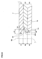
- Fig. 3 is a cross sectional view along a line B-B in Fig. 2, and a portion having no break line extends along the sipe side wall.
- the sipe 7 shown in Fig. 2 is shown as a so-called closed-type sipe in which both the one end E1 and the other end E2 are not open to the main groove 3 or the tread end e.
- it may be constituted by an open-type sipe in which at least one end (or both ends) is open to the main groove 3 or the tread end e.
- the open top end 10 of the sipe 7 includes a zigzag part 7a between the one end E1 and the other end E2.
- the sipe 7 in accordance with the present embodiment is structured only by the zigzag part 7a.
- the sipe of course includes a structure in which a portion extending linearly in a tire axial direction is provided in both ends or one end side of the zigzag part 7a.
- the zigzag part 7a is structured by using a curve and/or a straight line.
- the curve includes, for example, a wave form obtained by connecting a plurality of circular arcs, a sine wave form and the like.
- the zigzag part 7a includes a structure using both the straight line and the curve.
- a broken line zigzag shape using the straight line is preferable as in the present embodiment, and a structure obtained by chamfering a zigzag corner with a circular arc is more preferable.
- the zigzag part 7a is desirably structured, for example, such that an amplitude S of the zigzag is 0.7 to 10.0 mm, and more preferably 0.7 to 2.0 mm.
- the zigzag part 7a is preferably structured such that one pitch Y in a longitudinal direction is 0.6 to 10.0 times the amplitude S, and more preferably 0.6 to 2.5 times.
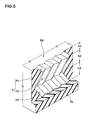
- the sipe 7 includes a first portion 11, a second portion 12 and a third portion 13, as shown in Figs. 3 to 5.
- the first portion 11 extends to a side of the bottom 7e with being inclined (displaced) to one side (a right side in Fig. 3) in the longitudinal direction of the sipe while substantially keeping the shape of the zigzag part of the open top end 10.
- a displacement length along the longitudinal direction of the sipe is indicated by reference symbol "a1" in the first portion 11.
- a length in the radial direction of the first portion 11 is indicated by reference symbol "h1".
- a ratio (a1/h1) of the displacement length a1 of the first portion 11 and the length h1 in the radial direction thereof is defined as a first displacement pitch ⁇ 1.
- the first displacement pitch ⁇ 1 expresses a degree of the slope (the displacement) of the first portion 11 with respect to the tire radial line, and is equal to a tangent of an angle ⁇ 1 (tan ⁇ 1) shown in Fig. 3.
- the angle ⁇ 1 is an angle between a line La drawn at a time when any one point of the zigzag part 7a of the first portion 11 is displaced (for example, a ridge line of a corner is preferable), and the tire radial line, when facing the surface of the sipe from the front (when viewing from the perpendicular direction to the longitudinal direction).
- the second portion 12 is connected to an inner side in a radial direction of the first portion 11 and is extended to the side of the bottom 7e, where the zigzag part 7a is inclined to an inverse direction (a left side in Fig. 3) to the first portion 11.
- the second portion 12 is provided in a side of the bottom 7e rather than the first portion 11.
- a displacement length along the longitudinal direction of the second portion 12 is indicated by reference symbol "a2".
- the length in the radial direction of the second portion 12 is indicated by reference symbol "h2".
- the length h2 is larger than the length h1 in the radial direction of the first portion 11 (h2 > h1).
- a ratio (a2/h2) of the displacement length a2 of the second portion 12 and the length h2 in the radial direction thereof is defined as a second displacement pitch ⁇ 2.
- the second displacement pitch ⁇ 2 expresses a degree of the slope (the displacement) of the second portion 12 with respect to the tire radial line, and is equal to a tangent of an angle ⁇ 2 (tan ⁇ 2) shown in Fig. 3.
- the angle ⁇ 2 is an angle between a line Lb drawn at a time when any one point of the second portion 12 is displaced (for example, a ridge line of a corner is preferable), and the tire radial line, when facing the surface of the sipe from the front.
- the second portion 12 has a small degree at which the sipe is inclined in the longitudinal direction with respect to the tire radial direction, in comparison with the first portion 11.
- the third portion 13 is connected to an inner side in the radial direction of the second portion 12 and is extended to the side of the bottom 7e, where the zigzag part 7a is inclined to an inverse direction (a right side in Fig. 3) to the second portion 12.
- the third portion 13 is provided further in a side of the bottom 7e rather than the second portion 12.
- a displacement length along the longitudinal direction of the third portion 13 is indicated by reference symbol "a3".
- the length in the radial direction of the third portion 13 is indicated by reference symbol "h3".
- the length h3 is larger than the length h2 in the radial direction of the second portion 12 (h1 ⁇ h2 ⁇ h3).
- a ratio (a3/h3) of the displacement length a3 of the third portion 13 and the length h3 in the radial direction thereof is defined as a third displacement pitch ⁇ 3.
- the third displacement pitch ⁇ 3 expresses a degree of the slope of the third portion 13 with respect to the tire radial line, and is equal to a tangent of an angle ⁇ 3 (tan ⁇ 3) shown in Fig. 3.
- the angle ⁇ 3 is an angle between a line Lc drawn at a time when any one point of the third portion 13 is displaced (a ridge line of a corner is preferable), and the tire radial line, in the case of opposing to the surface of the sipe, in the same manner as the angles ⁇ 1 and ⁇ 2.
- the third portion 13 has a small degree at which the sipe is inclined in the longitudinal direction with respect to the tire radial direction, in comparison with the second portion 11 ( ⁇ 1 > ⁇ 2 > ⁇ 3).
- the first displacement pitch ⁇ 1, the second displacement pitch ⁇ 2 and the third displacement pitch ⁇ 3 satisfy the following relation (1). ⁇ 1 > ⁇ 2 > ⁇ 3
- the displacement pitches ⁇ 1, ⁇ 2 and ⁇ 3 constitute an important parameter about an easiness of drawing the knife blade and the displacement of the sipe at the time of running.
- the displacement pitches ⁇ 1, ⁇ 2 and ⁇ 3 are large, an engaging force between the opposing sipe side wall is increased.
- This increases an integral property of the opposing sipe side wall so as to maintain the block rigidity high even in the case that the shear force at the time of running is applied to the tread element. Accordingly, the block pieces 5P divided by the sipe are not collapsed significantly largely, and the edge of the sipe can be properly brought into contact with the road surface.
- the knife blade can be easily drawn off from the vulcanized tire.
- the sipe 7 is hard to be opened as the sipe is closer to the bottom 7e. In other words, this means that the drawing resistance of the knife blade is larger in the side of the bottom sipe 7e of the sipe after vulcanizing the sipe 7.
- the sipe 7 in accordance with the present embodiment can lower the drawing resistance of the knife blade in the bottom side by making the displacement pitch smaller as the displacement portion is closer to the side of the bottom 7e. Accordingly, it is possible to solve the problem that the rubber chip and the dropout of the knife blade from the tire mold at the time of drawing off, and it is possible to improve the productivity. Further, as is apparent from Fig.
- the amplitudes d1, d2 and d3 of the sipe surface measured in the perpendicular direction to the depth direction and the longitudinal direction of the sipe of the first portion 11, the second portion 12 and the third portion 13 are substantially the same, however, in the case that the lengths in the tire radial direction of the respective displacement portions 11 to 13 satisfy the relation h1 ⁇ h2 ⁇ h3, the slope becomes more gentle as being closer to the bottom 7e side of the sipe. Accordingly, the drawing property of the knife blade is improved.
- the first portion 11 having the open top end 7a which is in contact with the road surface particularly tends to be slid opposing sipe side walls in the sipe 7 due to the larger shear force at the time of running. Accordingly, in the sipe 7 in accordance with the present embodiment, the displacement pitch ⁇ is increased as the displacement portion is closer to the road surface. Therefore, the closer to the road surface the portion is, the more largely the engaging force between the sipe surfaces can be obtained at the time of running. Accordingly, since the block rigidity is not deteriorated, it is possible to inhibit the sipe from being excessively displaced, and it is possible to properly bring the sipe edge into contact with the road surface. In other words, it is possible to establish both the running property on the ice road and the formability.
- the sipe 7 satisfies the following relations (2), (3) and (4). 0.3 ⁇ h1/h2 ⁇ 1.0 0.5 ⁇ h2/h3 ⁇ 1.0 h1/h2 ⁇ h2/h3
- the ratio (h1/h2) of the length h1 in the radial direction of the first portion 11 and the length h2 in the radial direction of the second portion 12 is equal to or less than 0.3, there is a tendency that the first portion 11 early disappears due to an abrasion, and the block rigidity is lowered.
- the ratio (h2 /h3) of the length h2 in the radial direction of the second portion 13 is equal to or less than 0.5, there is a tendency that the sufficient block rigidity can not be obtained at a later stage of the abrasion.
- the sipe 7 in this embodiment is shown as the sipe constituted by three portions comprising the first portion 11, the second portion 12 and the third portion 13, however, it may be constituted by a sipe in which a fourth displacement portion, a fifth displacement portion and the like are further included in the inner side in the tire radial direction of the third portion 13. Further, as in the embodiment mentioned above, the sipe 7 may be provided with a non-portion extending in the tire radial direction without being displaced in the longitudinal direction in the inner side in the tire radial direction of the third portion 13 (not shown), in addition to being structured only by the displacement portion.
- the length in the radial direction of the sipe 7 is preferably defined in accordance with the customs.
- the first displacement pitch ⁇ 1 is preferably equal to or more than 0.4, and more preferably equal to or more than 0. 7.
- the upper limit of the first displacement pitch ⁇ 1 is preferably equal to or less than 1.2, and more preferably equal to or less than 1.0.
- the ratio ( ⁇ 1/ ⁇ 2) of the second displacement pitch ⁇ 2 and the first displacement pitch ⁇ 1 is preferably equal to or more than 0.3, and more preferably equal to or more than 0.5.
- the ratio ( ⁇ 2/ ⁇ 1) mentioned above is less than 0.3, there is a tendency that the degree of the slope becomes excessively small, and the engaging force between the sipe surfaces is lowered.
- the ratio ( ⁇ 2/ ⁇ 1) is too large, an effect of improving the drawing property of the knife blade tends to be lowered.
- the upper limit of the ratio ( ⁇ 2/ ⁇ 1) is preferably equal to or less than 0.9, and more preferably equal to or less than 0.8.
- the ratio ( ⁇ 3/ ⁇ 2) of the second displacement pitch ⁇ 2 and the third displacement pitch ⁇ 3 is preferably equal to or more than 0.5, and more preferably equal to or more than 0.7, and the upper limit thereof is preferably equal to or less than 0.9, and more preferably equal to or less than 0.8.
- Fig. 6 shows another embodiment in accordance with the present invention.
- the first, second and third displacement pitches ⁇ 1, ⁇ 2 and ⁇ 3 satisfy the relation (1) mentioned above, the respective displacement lengths a1, a2 and a3 of the first, second and third portions 11, 12 and 13 satisfy the following relation (5).
- the sipe 7 can satisfy the drawing property of the knife blade and the edge effect on the ice road at a high level.
- Fig. 7 shows the open top end 10 of the sipe 7, as an embodiment in accordance with the present invention.
- the sipe 7 has one end E1 open to a side surface 5e of the block 5.
- the other end E2 of the sipe 7 exists in the inner portion of the block 5.
- reference symbol CL in Fig. 7 denotes a center line of the block dividing the block 5 into two sections in a width direction thereof.
- the zigzag part 7a of the sipe 7 includes a plurality of zigzag corners 14. In this embodiment, a narrow angle ⁇ of the zigzag corner 14 is larger as the zigzag corner 14 is closer to the center in the block width direction (that is, the width center line CL).
- the sipe 7 in accordance with the previous embodiment is shown as the sipe having the zigzag part 7a extending in the longitudinal direction at the same pitch Y as the zigzag amplitude S, however, in this embodiment, the shape of the zigzag part is changed in the longitudinal direction.
- the sipe 7 tends to be open in the side of the side surface 5e of the block 5 comparatively, however, the opening tendency is deteriorated as being closer to the width center line CL of the block 5. Accordingly, the knife blade is hard to be drawn as being closer to the width center line CL of the block 5.
- the narrow angle ⁇ of the zigzag corner is made larger as being closer to the center in the block width direction.
- the drawing property of the knife blade is further improved by employing the structure mentioned above.
- the narrow angle ⁇ is too large, there is a tendency that the engaging force between the sipe surfaces is lowered.
- the largest narrow angle ⁇ is preferably 90 to 130 degree, and more preferably 100 to 120 degree.
- the tread element is constituted by the block, however, the tread element of course includes the rib continuously extending in the tire circumferential direction.
- Fig. 8A there is produced a block model in which four sipes (having a common depth 9.0 mm and detailed specification in Table 1) are formed at regular intervals in a rectangular rubber block (width in a tire axial direction: 15 mm, length in a tire circumferential direction: 20 mm, height: 10 mm). Then, various tests are conducted thereto. Testing methods are as follows.
- the rigidity of the block model is estimated on the basis of the magnitude of the shear force F at this time. Results are expressed by an index obtained by setting the shear force of Comparative Example 1 to 100. The larger the numerical value is, the better the rigidity is.
- the rubber block is vulcanized by using the knife blade, and thereafter, the force required for drawing off the knife blade vertically is measured. Results are expressed by an index obtained by setting Comparative Example 1 to 100. The smaller the numerical value is, the better the property is.
Landscapes
- Engineering & Computer Science (AREA)
- Mechanical Engineering (AREA)
- Tires In General (AREA)
Applications Claiming Priority (2)
| Application Number | Priority Date | Filing Date | Title |
|---|---|---|---|
| JP2004004501 | 2004-01-09 | ||
| JP2004004501A JP4330455B2 (ja) | 2004-01-09 | 2004-01-09 | 空気入りタイヤ |
Publications (3)
| Publication Number | Publication Date |
|---|---|
| EP1555142A2 true EP1555142A2 (fr) | 2005-07-20 |
| EP1555142A3 EP1555142A3 (fr) | 2005-08-03 |
| EP1555142B1 EP1555142B1 (fr) | 2011-11-16 |
Family
ID=34616824
Family Applications (1)
| Application Number | Title | Priority Date | Filing Date |
|---|---|---|---|
| EP04028262A Ceased EP1555142B1 (fr) | 2004-01-09 | 2004-11-29 | Bandage pneumatique |
Country Status (4)
| Country | Link |
|---|---|
| US (1) | US7487810B2 (fr) |
| EP (1) | EP1555142B1 (fr) |
| JP (1) | JP4330455B2 (fr) |
| CN (1) | CN100569546C (fr) |
Cited By (11)
| Publication number | Priority date | Publication date | Assignee | Title |
|---|---|---|---|---|
| EP1652695A1 (fr) * | 2004-10-27 | 2006-05-03 | Sumitomo Rubber Industries, Ltd. | Pneumatique |
| EP1813446A4 (fr) * | 2004-11-08 | 2009-03-25 | Bridgestone Corp | Pneumatique |
| WO2010063751A1 (fr) * | 2008-12-05 | 2010-06-10 | Societe De Technologie Michelin | Bande de roulement pourvue d'incisions. |
| CN104044406A (zh) * | 2013-03-15 | 2014-09-17 | 住友橡胶工业株式会社 | 充气轮胎 |
| WO2015176958A1 (fr) * | 2014-05-20 | 2015-11-26 | Apollo Tyres Global R&D B.V. | Profil de pneu et forme de moulage |
| EP3153334A1 (fr) * | 2015-10-09 | 2017-04-12 | Sumitomo Rubber Industries, Ltd. | Pneu |
| EP3335910A1 (fr) * | 2016-11-11 | 2018-06-20 | Sumitomo Rubber Industries, Ltd. | Pneumatique |
| WO2018140851A1 (fr) | 2017-01-29 | 2018-08-02 | Bridgestone Americas Tire Operations, Llc | Lamelle de pneu tridimensionnelle |
| EP3600919A4 (fr) * | 2017-03-27 | 2020-10-28 | Bridgestone Bandag, LLC | Lamelle tridimensionnelle à oscillation variable |
| WO2023064704A1 (fr) * | 2021-10-16 | 2023-04-20 | Bridgestone Americas Tire Operations, Llc | Lamelle et/ou fente de verrouillage mutuel directionnel |
| WO2023064703A1 (fr) * | 2021-10-16 | 2023-04-20 | Bridgestone Americas Tire Operations, Llc | Lamelle et/ou fente de verrouillage directionnel avec chanfrein |
Families Citing this family (23)
| Publication number | Priority date | Publication date | Assignee | Title |
|---|---|---|---|---|
| JP4138688B2 (ja) * | 2004-03-25 | 2008-08-27 | 住友ゴム工業株式会社 | 空気入りタイヤ |
| US20120037288A1 (en) * | 2004-06-28 | 2012-02-16 | Bridgestone Corporation | Pneumatic tire |
| JP4516415B2 (ja) * | 2004-12-08 | 2010-08-04 | 住友ゴム工業株式会社 | 空気入りタイヤ |
| JP4751164B2 (ja) * | 2005-10-06 | 2011-08-17 | 株式会社ブリヂストン | 空気入りタイヤ |
| JP4751183B2 (ja) * | 2005-11-08 | 2011-08-17 | 株式会社ブリヂストン | 空気入りタイヤ |
| KR100722944B1 (ko) * | 2006-04-28 | 2007-05-30 | 한국타이어 주식회사 | 타이어 가류금형에 있어서의 커프 성형용 블레이드 |
| JP4211944B2 (ja) * | 2006-11-17 | 2009-01-21 | 東洋ゴム工業株式会社 | 空気入りタイヤ |
| EP2432652B1 (fr) * | 2009-05-19 | 2018-04-04 | Pirelli Tyre S.p.A. | Pneumatique pour un vehicule automobile |
| FR2968600A1 (fr) * | 2010-12-08 | 2012-06-15 | Michelin Soc Tech | Bande de roulement pour pneumatique neige |
| JP5480868B2 (ja) * | 2011-10-07 | 2014-04-23 | 住友ゴム工業株式会社 | 空気入りタイヤ |
| JP5647646B2 (ja) | 2012-06-08 | 2015-01-07 | 住友ゴム工業株式会社 | タイヤの加硫金型及び空気入りタイヤの製造方法 |
| NL2009980C2 (en) * | 2012-12-13 | 2014-06-16 | Ct Voor Tech Informatica B V | A method of producing glass products from glass product material and an assembly for performing said method. |
| JP5690375B2 (ja) * | 2013-06-05 | 2015-03-25 | 株式会社ブリヂストン | タイヤ |
| JP5926714B2 (ja) * | 2013-10-07 | 2016-05-25 | 住友ゴム工業株式会社 | 空気入りタイヤ |
| EP3113961B1 (fr) * | 2014-03-07 | 2019-01-30 | Bridgestone Americas Tire Operations, LLC | Bande de roulement présentant une lamelle |
| JP6329010B2 (ja) * | 2014-06-13 | 2018-05-23 | 株式会社ブリヂストン | 空気入りタイヤ |
| JP6483967B2 (ja) * | 2014-07-07 | 2019-03-13 | 株式会社ブリヂストン | 空気入りタイヤ |
| JP6646407B2 (ja) * | 2015-11-05 | 2020-02-14 | Toyo Tire株式会社 | 空気入りタイヤ |
| JP6554017B2 (ja) * | 2015-11-05 | 2019-07-31 | Toyo Tire株式会社 | 空気入りタイヤ |
| WO2018022827A1 (fr) | 2016-07-27 | 2018-02-01 | Bridgestone Americas Tire Operations, Llc | Lamelle de pneu tridimensionnelle |
| EP4209362B1 (fr) * | 2020-09-03 | 2024-12-11 | Sumitomo Rubber Industries, Ltd. | Pneumatique |
| US11807045B2 (en) | 2021-06-14 | 2023-11-07 | The Goodyear Tire & Rubber Company | Tire with hybrid sipe pattern |
| DE102022213492A1 (de) * | 2022-12-12 | 2024-06-13 | Continental Reifen Deutschland Gmbh | Fahrzeugluftreifen |
Family Cites Families (18)
| Publication number | Priority date | Publication date | Assignee | Title |
|---|---|---|---|---|
| FR2612129B1 (fr) * | 1987-03-10 | 1989-09-29 | Michelin & Cie | Bande de roulement pour pneumatique radial dont les elements en relief sont pourvus d'incisions presentant des traces en ligne brisee ou ondulee dans le sens de leurs profondeurs |
| AT401160B (de) * | 1991-05-21 | 1996-07-25 | Semperit Ag | Luftreifen mit einer lauffläche |
| FR2703002B1 (fr) * | 1993-03-25 | 1995-06-02 | Michelin & Cie | Bande de roulement pour pneumatique radial ayant des éléments en relief pourvus d'incisions. |
| FR2722144B1 (fr) * | 1994-07-05 | 1996-09-27 | Michelin & Cie | Bande de roulement pour pneumatique |
| JP4035177B2 (ja) * | 1995-12-14 | 2008-01-16 | 株式会社ブリヂストン | スタッドレス空気入りタイヤ |
| JPH09164815A (ja) * | 1995-12-14 | 1997-06-24 | Bridgestone Corp | スタッドレス空気入りタイヤ |
| DE19812778C2 (de) * | 1998-03-24 | 2002-07-04 | Continental Ag | Hochstabile Lamelle, Vulkanisationsform mit solchen Lamellen, Fahrzeugreifen mit Lauffläche, in die Einschnitte mittels solcher Lamellen gebracht sind |
| JP4278770B2 (ja) * | 1998-04-22 | 2009-06-17 | 株式会社ブリヂストン | 空気入りタイヤ |
| JP4424774B2 (ja) * | 1998-04-22 | 2010-03-03 | 株式会社ブリヂストン | 空気入りタイヤ |
| US6427737B1 (en) * | 1998-04-22 | 2002-08-06 | Bridgestone Corporation | Pneumatic tire having at least four sipes |
| JP2000177329A (ja) * | 1998-12-14 | 2000-06-27 | Ohtsu Tire & Rubber Co Ltd :The | タイヤトレッド |
| JP3504632B2 (ja) * | 2001-04-27 | 2004-03-08 | 東洋ゴム工業株式会社 | 空気入りタイヤ |
| JP3648179B2 (ja) * | 2001-07-18 | 2005-05-18 | 住友ゴム工業株式会社 | 空気入りタイヤ及びその加硫金型 |
| US7637295B2 (en) * | 2003-09-29 | 2009-12-29 | The Yokohama Rubber Co., Ltd. | Pneumatic tire with tread including sipes having bent portions formed with zigzag shape with amplitude in radial direction |
| JP4316452B2 (ja) * | 2003-09-29 | 2009-08-19 | 横浜ゴム株式会社 | 空気入りタイヤ |
| US7143799B2 (en) * | 2003-11-20 | 2006-12-05 | The Goodyear Tire & Rubber Company | Three-dimensional sipes for treads |
| JP3898692B2 (ja) * | 2003-12-03 | 2007-03-28 | 住友ゴム工業株式会社 | 空気入りタイヤ |
| JP4285609B2 (ja) * | 2004-09-06 | 2009-06-24 | 横浜ゴム株式会社 | 空気入りタイヤ |
-
2004
- 2004-01-09 JP JP2004004501A patent/JP4330455B2/ja not_active Expired - Fee Related
- 2004-11-29 EP EP04028262A patent/EP1555142B1/fr not_active Ceased
- 2004-12-08 US US11/006,584 patent/US7487810B2/en not_active Expired - Fee Related
- 2004-12-20 CN CNB200410104990XA patent/CN100569546C/zh not_active Expired - Fee Related
Non-Patent Citations (1)
| Title |
|---|
| None |
Cited By (20)
| Publication number | Priority date | Publication date | Assignee | Title |
|---|---|---|---|---|
| EP1652695A1 (fr) * | 2004-10-27 | 2006-05-03 | Sumitomo Rubber Industries, Ltd. | Pneumatique |
| US7334619B2 (en) | 2004-10-27 | 2008-02-26 | Sumitomo Rubber Industries, Ltd. | Pneumatic tire with blocks having zigzag sipes |
| EP1813446A4 (fr) * | 2004-11-08 | 2009-03-25 | Bridgestone Corp | Pneumatique |
| US9211767B2 (en) | 2008-12-05 | 2015-12-15 | Compagnie Generale Des Etablissements Michelin | Tread with incisions |
| CN102227324A (zh) * | 2008-12-05 | 2011-10-26 | 米其林技术公司 | 具有刀槽花纹的胎面 |
| EA018685B1 (ru) * | 2008-12-05 | 2013-09-30 | Компани Женераль Дез Этаблиссман Мишлен | Протектор с бороздками |
| CN102227324B (zh) * | 2008-12-05 | 2013-11-06 | 米其林企业总公司 | 具有刀槽花纹的胎面 |
| WO2010063751A1 (fr) * | 2008-12-05 | 2010-06-10 | Societe De Technologie Michelin | Bande de roulement pourvue d'incisions. |
| FR2939360A1 (fr) * | 2008-12-05 | 2010-06-11 | Michelin Soc Tech | Bande de roulement pourvue d'incisions |
| CN104044406A (zh) * | 2013-03-15 | 2014-09-17 | 住友橡胶工业株式会社 | 充气轮胎 |
| WO2015176958A1 (fr) * | 2014-05-20 | 2015-11-26 | Apollo Tyres Global R&D B.V. | Profil de pneu et forme de moulage |
| US10696102B2 (en) | 2015-10-09 | 2020-06-30 | Sumitomo Rubber Industries, Ltd. | Tire |
| EP3153334A1 (fr) * | 2015-10-09 | 2017-04-12 | Sumitomo Rubber Industries, Ltd. | Pneu |
| EP3335910A1 (fr) * | 2016-11-11 | 2018-06-20 | Sumitomo Rubber Industries, Ltd. | Pneumatique |
| WO2018140851A1 (fr) | 2017-01-29 | 2018-08-02 | Bridgestone Americas Tire Operations, Llc | Lamelle de pneu tridimensionnelle |
| EP3573849A4 (fr) * | 2017-01-29 | 2020-11-04 | Bridgestone Americas Tire Operations, LLC | Lamelle de pneu tridimensionnelle |
| EP3600919A4 (fr) * | 2017-03-27 | 2020-10-28 | Bridgestone Bandag, LLC | Lamelle tridimensionnelle à oscillation variable |
| US12168372B2 (en) | 2017-03-27 | 2024-12-17 | Bridgestone Bandag, Llc | Variable oscillation three dimensional sipe |
| WO2023064704A1 (fr) * | 2021-10-16 | 2023-04-20 | Bridgestone Americas Tire Operations, Llc | Lamelle et/ou fente de verrouillage mutuel directionnel |
| WO2023064703A1 (fr) * | 2021-10-16 | 2023-04-20 | Bridgestone Americas Tire Operations, Llc | Lamelle et/ou fente de verrouillage directionnel avec chanfrein |
Also Published As
| Publication number | Publication date |
|---|---|
| CN100569546C (zh) | 2009-12-16 |
| CN1636769A (zh) | 2005-07-13 |
| US7487810B2 (en) | 2009-02-10 |
| EP1555142A3 (fr) | 2005-08-03 |
| JP2005193867A (ja) | 2005-07-21 |
| JP4330455B2 (ja) | 2009-09-16 |
| US20050150581A1 (en) | 2005-07-14 |
| EP1555142B1 (fr) | 2011-11-16 |
Similar Documents
| Publication | Publication Date | Title |
|---|---|---|
| EP1555142A2 (fr) | Bandage pneumatique | |
| JP3648179B2 (ja) | 空気入りタイヤ及びその加硫金型 | |
| CN102442166B (zh) | 充气轮胎 | |
| CN102227325B (zh) | 包括设有突起的刀槽花纹的轮胎胎面 | |
| EP2762333B1 (fr) | Pneu | |
| JP4446077B2 (ja) | 空気入りタイヤ | |
| US7516767B2 (en) | Pneumatic tire with tread having zigzag sipes | |
| CN100532141C (zh) | 充气轮胎 | |
| JP3359000B2 (ja) | 空気入りタイヤ | |
| CN101372195A (zh) | 充气轮胎 | |
| CN104024002A (zh) | 充气轮胎 | |
| US8511357B2 (en) | Pneumatic tire with tread having main grooves and sipes | |
| CN107921827B (zh) | 轮胎 | |
| JPH0994829A (ja) | 加硫成形モールド及びこれを用いて製造された空気入 りタイヤ | |
| US8181683B2 (en) | Pneumatic tire with tread having upper surface sipes and wall surface sipes | |
| CN106494158B (zh) | 充气轮胎 | |
| JP3499995B2 (ja) | 空気入りタイヤ | |
| JP2015131642A (ja) | 空気入りタイヤ | |
| JP4526081B2 (ja) | 空気入りタイヤ | |
| JP4306847B2 (ja) | 空気入りタイヤ | |
| JP4628151B2 (ja) | 空気入りタイヤ | |
| JPH0994828A (ja) | 加硫成形モールド及びこれを用いて製造された空気入 りタイヤ | |
| JP2013071647A (ja) | 空気入りタイヤ | |
| CN112654512B (zh) | 轮胎 | |
| JP4765406B2 (ja) | 空気入りタイヤ |
Legal Events
| Date | Code | Title | Description |
|---|---|---|---|
| PUAI | Public reference made under article 153(3) epc to a published international application that has entered the european phase |
Free format text: ORIGINAL CODE: 0009012 |
|
| PUAL | Search report despatched |
Free format text: ORIGINAL CODE: 0009013 |
|
| AK | Designated contracting states |
Kind code of ref document: A2 Designated state(s): AT BE BG CH CY CZ DE DK EE ES FI FR GB GR HU IE IS IT LI LU MC NL PL PT RO SE SI SK TR |
|
| AX | Request for extension of the european patent |
Extension state: AL HR LT LV MK YU |
|
| AK | Designated contracting states |
Kind code of ref document: A3 Designated state(s): AT BE BG CH CY CZ DE DK EE ES FI FR GB GR HU IE IS IT LI LU MC NL PL PT RO SE SI SK TR |
|
| AX | Request for extension of the european patent |
Extension state: AL HR LT LV MK YU |
|
| 17P | Request for examination filed |
Effective date: 20050831 |
|
| AKX | Designation fees paid |
Designated state(s): DE FR GB |
|
| 17Q | First examination report despatched |
Effective date: 20071126 |
|
| GRAP | Despatch of communication of intention to grant a patent |
Free format text: ORIGINAL CODE: EPIDOSNIGR1 |
|
| GRAS | Grant fee paid |
Free format text: ORIGINAL CODE: EPIDOSNIGR3 |
|
| GRAA | (expected) grant |
Free format text: ORIGINAL CODE: 0009210 |
|
| AK | Designated contracting states |
Kind code of ref document: B1 Designated state(s): DE FR GB |
|
| REG | Reference to a national code |
Ref country code: GB Ref legal event code: FG4D |
|
| REG | Reference to a national code |
Ref country code: DE Ref legal event code: R096 Ref document number: 602004035295 Country of ref document: DE Effective date: 20120126 |
|
| PLBE | No opposition filed within time limit |
Free format text: ORIGINAL CODE: 0009261 |
|
| STAA | Information on the status of an ep patent application or granted ep patent |
Free format text: STATUS: NO OPPOSITION FILED WITHIN TIME LIMIT |
|
| 26N | No opposition filed |
Effective date: 20120817 |
|
| REG | Reference to a national code |
Ref country code: DE Ref legal event code: R097 Ref document number: 602004035295 Country of ref document: DE Effective date: 20120817 |
|
| PGFP | Annual fee paid to national office [announced via postgrant information from national office to epo] |
Ref country code: GB Payment date: 20141126 Year of fee payment: 11 |
|
| REG | Reference to a national code |
Ref country code: FR Ref legal event code: PLFP Year of fee payment: 12 |
|
| GBPC | Gb: european patent ceased through non-payment of renewal fee |
Effective date: 20151129 |
|
| REG | Reference to a national code |
Ref country code: FR Ref legal event code: PLFP Year of fee payment: 13 |
|
| PG25 | Lapsed in a contracting state [announced via postgrant information from national office to epo] |
Ref country code: GB Free format text: LAPSE BECAUSE OF NON-PAYMENT OF DUE FEES Effective date: 20151129 |
|
| REG | Reference to a national code |
Ref country code: FR Ref legal event code: PLFP Year of fee payment: 14 |
|
| PGFP | Annual fee paid to national office [announced via postgrant information from national office to epo] |
Ref country code: FR Payment date: 20171012 Year of fee payment: 14 |
|
| PG25 | Lapsed in a contracting state [announced via postgrant information from national office to epo] |
Ref country code: FR Free format text: LAPSE BECAUSE OF NON-PAYMENT OF DUE FEES Effective date: 20181130 |
|
| PGFP | Annual fee paid to national office [announced via postgrant information from national office to epo] |
Ref country code: DE Payment date: 20211005 Year of fee payment: 18 |
|
| REG | Reference to a national code |
Ref country code: DE Ref legal event code: R119 Ref document number: 602004035295 Country of ref document: DE |
|
| PG25 | Lapsed in a contracting state [announced via postgrant information from national office to epo] |
Ref country code: DE Free format text: LAPSE BECAUSE OF NON-PAYMENT OF DUE FEES Effective date: 20230601 |