EP1555137B1 - Verfahren zur tintenstrahlaufzeichnung - Google Patents
Verfahren zur tintenstrahlaufzeichnung Download PDFInfo
- Publication number
- EP1555137B1 EP1555137B1 EP20030758862 EP03758862A EP1555137B1 EP 1555137 B1 EP1555137 B1 EP 1555137B1 EP 20030758862 EP20030758862 EP 20030758862 EP 03758862 A EP03758862 A EP 03758862A EP 1555137 B1 EP1555137 B1 EP 1555137B1
- Authority
- EP
- European Patent Office
- Prior art keywords
- reaction liquid
- pigment
- ink
- recording medium
- recording
- Prior art date
- Legal status (The legal status is an assumption and is not a legal conclusion. Google has not performed a legal analysis and makes no representation as to the accuracy of the status listed.)
- Expired - Lifetime
Links
- 238000000034 method Methods 0.000 title claims description 78
- 239000000049 pigment Substances 0.000 claims description 204
- 239000012295 chemical reaction liquid Substances 0.000 claims description 157
- 230000002776 aggregation Effects 0.000 claims description 31
- 239000000835 fiber Substances 0.000 claims description 29
- 238000005054 agglomeration Methods 0.000 claims description 26
- 239000004094 surface-active agent Substances 0.000 claims description 23
- XLYOFNOQVPJJNP-UHFFFAOYSA-N water Substances O XLYOFNOQVPJJNP-UHFFFAOYSA-N 0.000 claims description 16
- 229910052751 metal Inorganic materials 0.000 claims description 12
- 239000002184 metal Substances 0.000 claims description 12
- 150000003839 salts Chemical class 0.000 claims description 11
- 239000002904 solvent Substances 0.000 claims description 9
- 230000005012 migration Effects 0.000 claims description 2
- 238000013508 migration Methods 0.000 claims description 2
- 239000000976 ink Substances 0.000 description 198
- 239000002609 medium Substances 0.000 description 112
- 239000007788 liquid Substances 0.000 description 58
- 239000000123 paper Substances 0.000 description 34
- 239000000203 mixture Substances 0.000 description 23
- 238000011161 development Methods 0.000 description 20
- 230000018109 developmental process Effects 0.000 description 20
- 230000000052 comparative effect Effects 0.000 description 17
- MTHSVFCYNBDYFN-UHFFFAOYSA-N diethylene glycol Chemical compound OCCOCCO MTHSVFCYNBDYFN-UHFFFAOYSA-N 0.000 description 17
- -1 polyoxyethylene Polymers 0.000 description 17
- LYCAIKOWRPUZTN-UHFFFAOYSA-N Ethylene glycol Chemical compound OCCO LYCAIKOWRPUZTN-UHFFFAOYSA-N 0.000 description 16
- 230000000740 bleeding effect Effects 0.000 description 15
- 238000006243 chemical reaction Methods 0.000 description 15
- 239000011347 resin Substances 0.000 description 15
- 229920005989 resin Polymers 0.000 description 15
- 229910021645 metal ion Inorganic materials 0.000 description 14
- 239000006185 dispersion Substances 0.000 description 13
- PEDCQBHIVMGVHV-UHFFFAOYSA-N Glycerine Chemical compound OCC(O)CO PEDCQBHIVMGVHV-UHFFFAOYSA-N 0.000 description 12
- 239000002245 particle Substances 0.000 description 12
- 230000035515 penetration Effects 0.000 description 11
- 238000007639 printing Methods 0.000 description 11
- 230000008569 process Effects 0.000 description 11
- 238000009736 wetting Methods 0.000 description 10
- LFQSCWFLJHTTHZ-UHFFFAOYSA-N Ethanol Chemical compound CCO LFQSCWFLJHTTHZ-UHFFFAOYSA-N 0.000 description 9
- KFZMGEQAYNKOFK-UHFFFAOYSA-N Isopropanol Chemical compound CC(C)O KFZMGEQAYNKOFK-UHFFFAOYSA-N 0.000 description 9
- 238000010521 absorption reaction Methods 0.000 description 9
- 239000003086 colorant Substances 0.000 description 9
- RTZKZFJDLAIYFH-UHFFFAOYSA-N Diethyl ether Chemical compound CCOCC RTZKZFJDLAIYFH-UHFFFAOYSA-N 0.000 description 8
- 239000002270 dispersing agent Substances 0.000 description 8
- 238000002360 preparation method Methods 0.000 description 8
- 239000006229 carbon black Substances 0.000 description 7
- OKTJSMMVPCPJKN-UHFFFAOYSA-N Carbon Chemical compound [C] OKTJSMMVPCPJKN-UHFFFAOYSA-N 0.000 description 6
- OKKJLVBELUTLKV-UHFFFAOYSA-N Methanol Chemical compound OC OKKJLVBELUTLKV-UHFFFAOYSA-N 0.000 description 6
- ZMXDDKWLCZADIW-UHFFFAOYSA-N N,N-Dimethylformamide Chemical compound CN(C)C=O ZMXDDKWLCZADIW-UHFFFAOYSA-N 0.000 description 6
- LRHPLDYGYMQRHN-UHFFFAOYSA-N N-Butanol Chemical compound CCCCO LRHPLDYGYMQRHN-UHFFFAOYSA-N 0.000 description 6
- SECXISVLQFMRJM-UHFFFAOYSA-N N-Methylpyrrolidone Chemical compound CN1CCCC1=O SECXISVLQFMRJM-UHFFFAOYSA-N 0.000 description 6
- KWYUFKZDYYNOTN-UHFFFAOYSA-M Potassium hydroxide Chemical compound [OH-].[K+] KWYUFKZDYYNOTN-UHFFFAOYSA-M 0.000 description 6
- DNIAPMSPPWPWGF-UHFFFAOYSA-N Propylene glycol Chemical compound CC(O)CO DNIAPMSPPWPWGF-UHFFFAOYSA-N 0.000 description 6
- HEMHJVSKTPXQMS-UHFFFAOYSA-M Sodium hydroxide Chemical compound [OH-].[Na+] HEMHJVSKTPXQMS-UHFFFAOYSA-M 0.000 description 6
- 238000004040 coloring Methods 0.000 description 6
- 239000003960 organic solvent Substances 0.000 description 6
- 238000004220 aggregation Methods 0.000 description 5
- 238000010276 construction Methods 0.000 description 5
- 230000003247 decreasing effect Effects 0.000 description 5
- 239000008367 deionised water Substances 0.000 description 5
- 229910021641 deionized water Inorganic materials 0.000 description 5
- 238000000635 electron micrograph Methods 0.000 description 5
- 235000019441 ethanol Nutrition 0.000 description 5
- 239000004615 ingredient Substances 0.000 description 5
- 150000002500 ions Chemical class 0.000 description 5
- SVTBMSDMJJWYQN-UHFFFAOYSA-N 2-methylpentane-2,4-diol Chemical compound CC(O)CC(C)(C)O SVTBMSDMJJWYQN-UHFFFAOYSA-N 0.000 description 4
- CSCPPACGZOOCGX-UHFFFAOYSA-N Acetone Chemical compound CC(C)=O CSCPPACGZOOCGX-UHFFFAOYSA-N 0.000 description 4
- PPBRXRYQALVLMV-UHFFFAOYSA-N Styrene Chemical compound C=CC1=CC=CC=C1 PPBRXRYQALVLMV-UHFFFAOYSA-N 0.000 description 4
- WYURNTSHIVDZCO-UHFFFAOYSA-N Tetrahydrofuran Chemical compound C1CCOC1 WYURNTSHIVDZCO-UHFFFAOYSA-N 0.000 description 4
- 125000004432 carbon atom Chemical group C* 0.000 description 4
- 238000012217 deletion Methods 0.000 description 4
- 230000037430 deletion Effects 0.000 description 4
- 238000009826 distribution Methods 0.000 description 4
- 150000002148 esters Chemical class 0.000 description 4
- 125000001495 ethyl group Chemical group [H]C([H])([H])C([H])([H])* 0.000 description 4
- 238000011156 evaluation Methods 0.000 description 4
- 238000000227 grinding Methods 0.000 description 4
- 238000005259 measurement Methods 0.000 description 4
- 239000004576 sand Substances 0.000 description 4
- 239000000126 substance Substances 0.000 description 4
- 150000005846 sugar alcohols Polymers 0.000 description 4
- 238000012360 testing method Methods 0.000 description 4
- WMFOQBRAJBCJND-UHFFFAOYSA-M Lithium hydroxide Chemical compound [Li+].[OH-] WMFOQBRAJBCJND-UHFFFAOYSA-M 0.000 description 3
- DKGAVHZHDRPRBM-UHFFFAOYSA-N Tert-Butanol Chemical compound CC(C)(C)O DKGAVHZHDRPRBM-UHFFFAOYSA-N 0.000 description 3
- GSEJCLTVZPLZKY-UHFFFAOYSA-N Triethanolamine Chemical compound OCCN(CCO)CCO GSEJCLTVZPLZKY-UHFFFAOYSA-N 0.000 description 3
- 239000000654 additive Substances 0.000 description 3
- 150000005215 alkyl ethers Chemical class 0.000 description 3
- 229910000147 aluminium phosphate Inorganic materials 0.000 description 3
- 150000001412 amines Chemical class 0.000 description 3
- 239000002585 base Substances 0.000 description 3
- 238000009835 boiling Methods 0.000 description 3
- BTANRVKWQNVYAZ-UHFFFAOYSA-N butan-2-ol Chemical compound CCC(C)O BTANRVKWQNVYAZ-UHFFFAOYSA-N 0.000 description 3
- 125000003178 carboxy group Chemical group [H]OC(*)=O 0.000 description 3
- 125000002091 cationic group Chemical group 0.000 description 3
- PZTQVMXMKVTIRC-UHFFFAOYSA-L chembl2028348 Chemical compound [Ca+2].[O-]S(=O)(=O)C1=CC(C)=CC=C1N=NC1=C(O)C(C([O-])=O)=CC2=CC=CC=C12 PZTQVMXMKVTIRC-UHFFFAOYSA-L 0.000 description 3
- 239000003795 chemical substances by application Substances 0.000 description 3
- XCJYREBRNVKWGJ-UHFFFAOYSA-N copper(II) phthalocyanine Chemical compound [Cu+2].C12=CC=CC=C2C(N=C2[N-]C(C3=CC=CC=C32)=N2)=NC1=NC([C]1C=CC=CC1=1)=NC=1N=C1[C]3C=CC=CC3=C2[N-]1 XCJYREBRNVKWGJ-UHFFFAOYSA-N 0.000 description 3
- 238000000151 deposition Methods 0.000 description 3
- SWXVUIWOUIDPGS-UHFFFAOYSA-N diacetone alcohol Natural products CC(=O)CC(C)(C)O SWXVUIWOUIDPGS-UHFFFAOYSA-N 0.000 description 3
- QFXZANXYUCUTQH-UHFFFAOYSA-N ethynol Chemical compound OC#C QFXZANXYUCUTQH-UHFFFAOYSA-N 0.000 description 3
- 238000004519 manufacturing process Methods 0.000 description 3
- 238000002156 mixing Methods 0.000 description 3
- NBIIXXVUZAFLBC-UHFFFAOYSA-N phosphoric acid Substances OP(O)(O)=O NBIIXXVUZAFLBC-UHFFFAOYSA-N 0.000 description 3
- PUPZLCDOIYMWBV-UHFFFAOYSA-N (+/-)-1,3-Butanediol Chemical compound CC(O)CCO PUPZLCDOIYMWBV-UHFFFAOYSA-N 0.000 description 2
- ZWVMLYRJXORSEP-UHFFFAOYSA-N 1,2,6-Hexanetriol Chemical compound OCCCCC(O)CO ZWVMLYRJXORSEP-UHFFFAOYSA-N 0.000 description 2
- RYHBNJHYFVUHQT-UHFFFAOYSA-N 1,4-Dioxane Chemical compound C1COCCO1 RYHBNJHYFVUHQT-UHFFFAOYSA-N 0.000 description 2
- IGGDKDTUCAWDAN-UHFFFAOYSA-N 1-vinylnaphthalene Chemical compound C1=CC=C2C(C=C)=CC=CC2=C1 IGGDKDTUCAWDAN-UHFFFAOYSA-N 0.000 description 2
- SMZOUWXMTYCWNB-UHFFFAOYSA-N 2-(2-methoxy-5-methylphenyl)ethanamine Chemical compound COC1=CC=C(C)C=C1CCN SMZOUWXMTYCWNB-UHFFFAOYSA-N 0.000 description 2
- HZAXFHJVJLSVMW-UHFFFAOYSA-N 2-Aminoethan-1-ol Chemical compound NCCO HZAXFHJVJLSVMW-UHFFFAOYSA-N 0.000 description 2
- NIXOWILDQLNWCW-UHFFFAOYSA-N 2-Propenoic acid Natural products OC(=O)C=C NIXOWILDQLNWCW-UHFFFAOYSA-N 0.000 description 2
- QGZKDVFQNNGYKY-UHFFFAOYSA-N Ammonia Chemical compound N QGZKDVFQNNGYKY-UHFFFAOYSA-N 0.000 description 2
- IAZDPXIOMUYVGZ-UHFFFAOYSA-N Dimethylsulphoxide Chemical compound CS(C)=O IAZDPXIOMUYVGZ-UHFFFAOYSA-N 0.000 description 2
- VZCYOOQTPOCHFL-OWOJBTEDSA-N Fumaric acid Chemical compound OC(=O)\C=C\C(O)=O VZCYOOQTPOCHFL-OWOJBTEDSA-N 0.000 description 2
- FXHOOIRPVKKKFG-UHFFFAOYSA-N N,N-Dimethylacetamide Chemical compound CN(C)C(C)=O FXHOOIRPVKKKFG-UHFFFAOYSA-N 0.000 description 2
- 239000002202 Polyethylene glycol Substances 0.000 description 2
- 239000002253 acid Substances 0.000 description 2
- 238000013019 agitation Methods 0.000 description 2
- 150000001408 amides Chemical class 0.000 description 2
- 239000003945 anionic surfactant Substances 0.000 description 2
- 239000012736 aqueous medium Substances 0.000 description 2
- 239000011230 binding agent Substances 0.000 description 2
- 230000033228 biological regulation Effects 0.000 description 2
- 230000015572 biosynthetic process Effects 0.000 description 2
- 230000008859 change Effects 0.000 description 2
- 230000001276 controlling effect Effects 0.000 description 2
- 230000006866 deterioration Effects 0.000 description 2
- ZBCBWPMODOFKDW-UHFFFAOYSA-N diethanolamine Chemical compound OCCNCCO ZBCBWPMODOFKDW-UHFFFAOYSA-N 0.000 description 2
- 238000009792 diffusion process Methods 0.000 description 2
- 239000002612 dispersion medium Substances 0.000 description 2
- 238000001035 drying Methods 0.000 description 2
- 239000000839 emulsion Substances 0.000 description 2
- 230000007613 environmental effect Effects 0.000 description 2
- 150000002170 ethers Chemical class 0.000 description 2
- 238000010438 heat treatment Methods 0.000 description 2
- 229940051250 hexylene glycol Drugs 0.000 description 2
- ZXEKIIBDNHEJCQ-UHFFFAOYSA-N isobutanol Chemical compound CC(C)CO ZXEKIIBDNHEJCQ-UHFFFAOYSA-N 0.000 description 2
- 150000002576 ketones Chemical class 0.000 description 2
- YIXJRHPUWRPCBB-UHFFFAOYSA-N magnesium nitrate Chemical compound [Mg+2].[O-][N+]([O-])=O.[O-][N+]([O-])=O YIXJRHPUWRPCBB-UHFFFAOYSA-N 0.000 description 2
- LVHBHZANLOWSRM-UHFFFAOYSA-N methylenebutanedioic acid Natural products OC(=O)CC(=C)C(O)=O LVHBHZANLOWSRM-UHFFFAOYSA-N 0.000 description 2
- 239000000178 monomer Substances 0.000 description 2
- 230000003287 optical effect Effects 0.000 description 2
- 238000012856 packing Methods 0.000 description 2
- 230000035699 permeability Effects 0.000 description 2
- 230000000704 physical effect Effects 0.000 description 2
- 229940099800 pigment red 48 Drugs 0.000 description 2
- 229920001515 polyalkylene glycol Polymers 0.000 description 2
- 229920001223 polyethylene glycol Polymers 0.000 description 2
- 229920001451 polypropylene glycol Polymers 0.000 description 2
- 239000003755 preservative agent Substances 0.000 description 2
- 230000002335 preservative effect Effects 0.000 description 2
- 230000002265 prevention Effects 0.000 description 2
- BDERNNFJNOPAEC-UHFFFAOYSA-N propan-1-ol Chemical compound CCCO BDERNNFJNOPAEC-UHFFFAOYSA-N 0.000 description 2
- 239000000376 reactant Substances 0.000 description 2
- 238000004513 sizing Methods 0.000 description 2
- 239000007787 solid Substances 0.000 description 2
- KDYFGRWQOYBRFD-UHFFFAOYSA-N succinic acid Chemical compound OC(=O)CCC(O)=O KDYFGRWQOYBRFD-UHFFFAOYSA-N 0.000 description 2
- YLQBMQCUIZJEEH-UHFFFAOYSA-N tetrahydrofuran Natural products C=1C=COC=1 YLQBMQCUIZJEEH-UHFFFAOYSA-N 0.000 description 2
- YODZTKMDCQEPHD-UHFFFAOYSA-N thiodiglycol Chemical compound OCCSCCO YODZTKMDCQEPHD-UHFFFAOYSA-N 0.000 description 2
- 229950006389 thiodiglycol Drugs 0.000 description 2
- VZCYOOQTPOCHFL-UHFFFAOYSA-N trans-butenedioic acid Natural products OC(=O)C=CC(O)=O VZCYOOQTPOCHFL-UHFFFAOYSA-N 0.000 description 2
- ZIBGPFATKBEMQZ-UHFFFAOYSA-N triethylene glycol Chemical compound OCCOCCOCCO ZIBGPFATKBEMQZ-UHFFFAOYSA-N 0.000 description 2
- DNIAPMSPPWPWGF-GSVOUGTGSA-N (R)-(-)-Propylene glycol Chemical class C[C@@H](O)CO DNIAPMSPPWPWGF-GSVOUGTGSA-N 0.000 description 1
- SBASXUCJHJRPEV-UHFFFAOYSA-N 2-(2-methoxyethoxy)ethanol Chemical compound COCCOCCO SBASXUCJHJRPEV-UHFFFAOYSA-N 0.000 description 1
- JAHNSTQSQJOJLO-UHFFFAOYSA-N 2-(3-fluorophenyl)-1h-imidazole Chemical compound FC1=CC=CC(C=2NC=CN=2)=C1 JAHNSTQSQJOJLO-UHFFFAOYSA-N 0.000 description 1
- XNWFRZJHXBZDAG-UHFFFAOYSA-N 2-METHOXYETHANOL Chemical compound COCCO XNWFRZJHXBZDAG-UHFFFAOYSA-N 0.000 description 1
- RSWGJHLUYNHPMX-UHFFFAOYSA-N Abietic-Saeure Natural products C12CCC(C(C)C)=CC2=CCC2C1(C)CCCC2(C)C(O)=O RSWGJHLUYNHPMX-UHFFFAOYSA-N 0.000 description 1
- HRPVXLWXLXDGHG-UHFFFAOYSA-N Acrylamide Chemical compound NC(=O)C=C HRPVXLWXLXDGHG-UHFFFAOYSA-N 0.000 description 1
- 229920002134 Carboxymethyl cellulose Polymers 0.000 description 1
- 241000557626 Corvus corax Species 0.000 description 1
- 206010013786 Dry skin Diseases 0.000 description 1
- DGAQECJNVWCQMB-PUAWFVPOSA-M Ilexoside XXIX Chemical compound C[C@@H]1CC[C@@]2(CC[C@@]3(C(=CC[C@H]4[C@]3(CC[C@@H]5[C@@]4(CC[C@@H](C5(C)C)OS(=O)(=O)[O-])C)C)[C@@H]2[C@]1(C)O)C)C(=O)O[C@H]6[C@@H]([C@H]([C@@H]([C@H](O6)CO)O)O)O.[Na+] DGAQECJNVWCQMB-PUAWFVPOSA-M 0.000 description 1
- WHNWPMSKXPGLAX-UHFFFAOYSA-N N-Vinyl-2-pyrrolidone Chemical compound C=CN1CCCC1=O WHNWPMSKXPGLAX-UHFFFAOYSA-N 0.000 description 1
- 229910002651 NO3 Inorganic materials 0.000 description 1
- 229910019142 PO4 Inorganic materials 0.000 description 1
- 229920003171 Poly (ethylene oxide) Polymers 0.000 description 1
- 239000004372 Polyvinyl alcohol Substances 0.000 description 1
- OFOBLEOULBTSOW-UHFFFAOYSA-N Propanedioic acid Natural products OC(=O)CC(O)=O OFOBLEOULBTSOW-UHFFFAOYSA-N 0.000 description 1
- KHPCPRHQVVSZAH-HUOMCSJISA-N Rosin Natural products O(C/C=C/c1ccccc1)[C@H]1[C@H](O)[C@@H](O)[C@@H](O)[C@@H](CO)O1 KHPCPRHQVVSZAH-HUOMCSJISA-N 0.000 description 1
- 229920001800 Shellac Polymers 0.000 description 1
- 229920002472 Starch Polymers 0.000 description 1
- 238000005411 Van der Waals force Methods 0.000 description 1
- XTXRWKRVRITETP-UHFFFAOYSA-N Vinyl acetate Chemical compound CC(=O)OC=C XTXRWKRVRITETP-UHFFFAOYSA-N 0.000 description 1
- QCWXUUIWCKQGHC-UHFFFAOYSA-N Zirconium Chemical compound [Zr] QCWXUUIWCKQGHC-UHFFFAOYSA-N 0.000 description 1
- 238000003916 acid precipitation Methods 0.000 description 1
- 230000002378 acidificating effect Effects 0.000 description 1
- 150000007513 acids Chemical class 0.000 description 1
- 150000001252 acrylic acid derivatives Chemical class 0.000 description 1
- 150000001298 alcohols Chemical class 0.000 description 1
- 239000003513 alkali Substances 0.000 description 1
- 229910052783 alkali metal Inorganic materials 0.000 description 1
- 150000001340 alkali metals Chemical class 0.000 description 1
- 125000005233 alkylalcohol group Chemical group 0.000 description 1
- 125000002947 alkylene group Chemical group 0.000 description 1
- 229910021529 ammonia Inorganic materials 0.000 description 1
- 150000001449 anionic compounds Chemical class 0.000 description 1
- 125000000129 anionic group Chemical group 0.000 description 1
- 150000001450 anions Chemical class 0.000 description 1
- 239000002518 antifoaming agent Substances 0.000 description 1
- 239000003963 antioxidant agent Substances 0.000 description 1
- 230000003078 antioxidant effect Effects 0.000 description 1
- 235000006708 antioxidants Nutrition 0.000 description 1
- LFZDEAVRTJKYAF-UHFFFAOYSA-L barium(2+) 2-[(2-hydroxynaphthalen-1-yl)diazenyl]naphthalene-1-sulfonate Chemical compound [Ba+2].C1=CC=CC2=C(S([O-])(=O)=O)C(N=NC3=C4C=CC=CC4=CC=C3O)=CC=C21.C1=CC=CC2=C(S([O-])(=O)=O)C(N=NC3=C4C=CC=CC4=CC=C3O)=CC=C21 LFZDEAVRTJKYAF-UHFFFAOYSA-L 0.000 description 1
- 239000011324 bead Substances 0.000 description 1
- 238000005452 bending Methods 0.000 description 1
- 229920001400 block copolymer Polymers 0.000 description 1
- 239000001768 carboxy methyl cellulose Substances 0.000 description 1
- 235000010948 carboxy methyl cellulose Nutrition 0.000 description 1
- 150000007942 carboxylates Chemical class 0.000 description 1
- 150000001732 carboxylic acid derivatives Chemical class 0.000 description 1
- 239000008112 carboxymethyl-cellulose Substances 0.000 description 1
- 150000001767 cationic compounds Chemical class 0.000 description 1
- UHZZMRAGKVHANO-UHFFFAOYSA-M chlormequat chloride Chemical compound [Cl-].C[N+](C)(C)CCCl UHZZMRAGKVHANO-UHFFFAOYSA-M 0.000 description 1
- 238000004140 cleaning Methods 0.000 description 1
- 239000011362 coarse particle Substances 0.000 description 1
- 150000001875 compounds Chemical class 0.000 description 1
- 239000000470 constituent Substances 0.000 description 1
- 229920001577 copolymer Polymers 0.000 description 1
- 230000007797 corrosion Effects 0.000 description 1
- 238000005260 corrosion Methods 0.000 description 1
- 230000001419 dependent effect Effects 0.000 description 1
- 230000000694 effects Effects 0.000 description 1
- 239000000945 filler Substances 0.000 description 1
- 239000001530 fumaric acid Substances 0.000 description 1
- 150000002237 fumaric acid derivatives Chemical class 0.000 description 1
- 229920000578 graft copolymer Polymers 0.000 description 1
- 150000002430 hydrocarbons Chemical group 0.000 description 1
- 150000004679 hydroxides Chemical class 0.000 description 1
- WGCNASOHLSPBMP-UHFFFAOYSA-N hydroxyacetaldehyde Natural products OCC=O WGCNASOHLSPBMP-UHFFFAOYSA-N 0.000 description 1
- 235000019239 indanthrene blue RS Nutrition 0.000 description 1
- UHOKSCJSTAHBSO-UHFFFAOYSA-N indanthrone blue Chemical compound C1=CC=C2C(=O)C3=CC=C4NC5=C6C(=O)C7=CC=CC=C7C(=O)C6=CC=C5NC4=C3C(=O)C2=C1 UHOKSCJSTAHBSO-UHFFFAOYSA-N 0.000 description 1
- 150000007529 inorganic bases Chemical class 0.000 description 1
- 229910052500 inorganic mineral Inorganic materials 0.000 description 1
- 229940035429 isobutyl alcohol Drugs 0.000 description 1
- 235000010187 litholrubine BK Nutrition 0.000 description 1
- 230000007774 longterm Effects 0.000 description 1
- VZCYOOQTPOCHFL-UPHRSURJSA-N maleic acid Chemical compound OC(=O)\C=C/C(O)=O VZCYOOQTPOCHFL-UPHRSURJSA-N 0.000 description 1
- 239000011976 maleic acid Substances 0.000 description 1
- 150000002688 maleic acid derivatives Chemical class 0.000 description 1
- 230000007246 mechanism Effects 0.000 description 1
- 239000012528 membrane Substances 0.000 description 1
- 239000011707 mineral Substances 0.000 description 1
- 239000000025 natural resin Substances 0.000 description 1
- 230000007935 neutral effect Effects 0.000 description 1
- 238000009828 non-uniform distribution Methods 0.000 description 1
- 150000007524 organic acids Chemical class 0.000 description 1
- 235000005985 organic acids Nutrition 0.000 description 1
- 150000002894 organic compounds Chemical class 0.000 description 1
- 239000003002 pH adjusting agent Substances 0.000 description 1
- 239000011087 paperboard Substances 0.000 description 1
- 230000000149 penetrating effect Effects 0.000 description 1
- PNJWIWWMYCMZRO-UHFFFAOYSA-N pent‐4‐en‐2‐one Natural products CC(=O)CC=C PNJWIWWMYCMZRO-UHFFFAOYSA-N 0.000 description 1
- 239000010452 phosphate Substances 0.000 description 1
- IEQIEDJGQAUEQZ-UHFFFAOYSA-N phthalocyanine Chemical compound N1C(N=C2C3=CC=CC=C3C(N=C3C4=CC=CC=C4C(=N4)N3)=N2)=C(C=CC=C2)C2=C1N=C1C2=CC=CC=C2C4=N1 IEQIEDJGQAUEQZ-UHFFFAOYSA-N 0.000 description 1
- 229940110337 pigment blue 1 Drugs 0.000 description 1
- 229940104573 pigment red 5 Drugs 0.000 description 1
- 229920000083 poly(allylamine) Polymers 0.000 description 1
- 229920000642 polymer Polymers 0.000 description 1
- 239000011118 polyvinyl acetate Substances 0.000 description 1
- 229920002689 polyvinyl acetate Polymers 0.000 description 1
- 229920002451 polyvinyl alcohol Polymers 0.000 description 1
- 239000011164 primary particle Substances 0.000 description 1
- HNJBEVLQSNELDL-UHFFFAOYSA-N pyrrolidin-2-one Chemical compound O=C1CCCN1 HNJBEVLQSNELDL-UHFFFAOYSA-N 0.000 description 1
- 229920005604 random copolymer Polymers 0.000 description 1
- 238000011084 recovery Methods 0.000 description 1
- 230000001105 regulatory effect Effects 0.000 description 1
- 230000004044 response Effects 0.000 description 1
- ZLGIYFNHBLSMPS-ATJNOEHPSA-N shellac Chemical compound OCCCCCC(O)C(O)CCCCCCCC(O)=O.C1C23[C@H](C(O)=O)CCC2[C@](C)(CO)[C@@H]1C(C(O)=O)=C[C@@H]3O ZLGIYFNHBLSMPS-ATJNOEHPSA-N 0.000 description 1
- 239000004208 shellac Substances 0.000 description 1
- 229940113147 shellac Drugs 0.000 description 1
- 235000013874 shellac Nutrition 0.000 description 1
- 229910052708 sodium Inorganic materials 0.000 description 1
- 239000011734 sodium Substances 0.000 description 1
- 239000011877 solvent mixture Substances 0.000 description 1
- 238000001179 sorption measurement Methods 0.000 description 1
- 238000009331 sowing Methods 0.000 description 1
- 239000008107 starch Substances 0.000 description 1
- 235000019698 starch Nutrition 0.000 description 1
- 150000003440 styrenes Chemical class 0.000 description 1
- 239000000758 substrate Substances 0.000 description 1
- 239000001384 succinic acid Substances 0.000 description 1
- HXJUTPCZVOIRIF-UHFFFAOYSA-N sulfolane Chemical compound O=S1(=O)CCCC1 HXJUTPCZVOIRIF-UHFFFAOYSA-N 0.000 description 1
- BDHFUVZGWQCTTF-UHFFFAOYSA-M sulfonate Chemical compound [O-]S(=O)=O BDHFUVZGWQCTTF-UHFFFAOYSA-M 0.000 description 1
- KHPCPRHQVVSZAH-UHFFFAOYSA-N trans-cinnamyl beta-D-glucopyranoside Natural products OC1C(O)C(O)C(CO)OC1OCC=CC1=CC=CC=C1 KHPCPRHQVVSZAH-UHFFFAOYSA-N 0.000 description 1
- JLGLQAWTXXGVEM-UHFFFAOYSA-N triethylene glycol monomethyl ether Chemical compound COCCOCCOCCO JLGLQAWTXXGVEM-UHFFFAOYSA-N 0.000 description 1
- JSPLKZUTYZBBKA-UHFFFAOYSA-N trioxidane Chemical class OOO JSPLKZUTYZBBKA-UHFFFAOYSA-N 0.000 description 1
- UGCDBQWJXSAYIL-UHFFFAOYSA-N vat blue 6 Chemical compound O=C1C2=CC=CC=C2C(=O)C(C=C2Cl)=C1C1=C2NC2=C(C(=O)C=3C(=CC=CC=3)C3=O)C3=CC(Cl)=C2N1 UGCDBQWJXSAYIL-UHFFFAOYSA-N 0.000 description 1
- 239000004034 viscosity adjusting agent Substances 0.000 description 1
- 239000001052 yellow pigment Substances 0.000 description 1
- 229910052726 zirconium Inorganic materials 0.000 description 1
Images


Classifications
-
- B—PERFORMING OPERATIONS; TRANSPORTING
- B41—PRINTING; LINING MACHINES; TYPEWRITERS; STAMPS
- B41M—PRINTING, DUPLICATING, MARKING, OR COPYING PROCESSES; COLOUR PRINTING
- B41M5/00—Duplicating or marking methods; Sheet materials for use therein
-
- B—PERFORMING OPERATIONS; TRANSPORTING
- B41—PRINTING; LINING MACHINES; TYPEWRITERS; STAMPS
- B41M—PRINTING, DUPLICATING, MARKING, OR COPYING PROCESSES; COLOUR PRINTING
- B41M5/00—Duplicating or marking methods; Sheet materials for use therein
- B41M5/50—Recording sheets characterised by the coating used to improve ink, dye or pigment receptivity, e.g. for ink-jet or thermal dye transfer recording
- B41M5/52—Macromolecular coatings
- B41M5/5218—Macromolecular coatings characterised by inorganic additives, e.g. pigments, clays
-
- B—PERFORMING OPERATIONS; TRANSPORTING
- B41—PRINTING; LINING MACHINES; TYPEWRITERS; STAMPS
- B41J—TYPEWRITERS; SELECTIVE PRINTING MECHANISMS, i.e. MECHANISMS PRINTING OTHERWISE THAN FROM A FORME; CORRECTION OF TYPOGRAPHICAL ERRORS
- B41J2/00—Typewriters or selective printing mechanisms characterised by the printing or marking process for which they are designed
- B41J2/005—Typewriters or selective printing mechanisms characterised by the printing or marking process for which they are designed characterised by bringing liquid or particles selectively into contact with a printing material
- B41J2/01—Ink jet
- B41J2/21—Ink jet for multi-colour printing
- B41J2/2107—Ink jet for multi-colour printing characterised by the ink properties
- B41J2/2114—Ejecting specialized liquids, e.g. transparent or processing liquids
-
- B—PERFORMING OPERATIONS; TRANSPORTING
- B41—PRINTING; LINING MACHINES; TYPEWRITERS; STAMPS
- B41M—PRINTING, DUPLICATING, MARKING, OR COPYING PROCESSES; COLOUR PRINTING
- B41M5/00—Duplicating or marking methods; Sheet materials for use therein
- B41M5/0011—Pre-treatment or treatment during printing of the recording material, e.g. heating, irradiating
- B41M5/0017—Application of ink-fixing material, e.g. mordant, precipitating agent, on the substrate prior to printing, e.g. by ink-jet printing, coating or spraying
-
- C—CHEMISTRY; METALLURGY
- C09—DYES; PAINTS; POLISHES; NATURAL RESINS; ADHESIVES; COMPOSITIONS NOT OTHERWISE PROVIDED FOR; APPLICATIONS OF MATERIALS NOT OTHERWISE PROVIDED FOR
- C09D—COATING COMPOSITIONS, e.g. PAINTS, VARNISHES OR LACQUERS; FILLING PASTES; CHEMICAL PAINT OR INK REMOVERS; INKS; CORRECTING FLUIDS; WOODSTAINS; PASTES OR SOLIDS FOR COLOURING OR PRINTING; USE OF MATERIALS THEREFOR
- C09D11/00—Inks
- C09D11/30—Inkjet printing inks
Definitions
- the present invention relates to an inkjet recording method, in particular, to an inkjet recording method which provides high-quality color images on recording media, such as plain paper, which include fibers capable of absorbing ink components.
- Inkjet recording methods are such methods that recording is performed by ejecting and depositing droplets of a recording liquid (ink) onto recording media such as paper.
- a method in which an electrothermal converter, as ink-ejecting energy supplying means, is used to provide thermal energy for the ink so as to produce bubbles to eject ink droplets by means of the bubbles a high-density multi-orifice recording head can be easily realized and high-resolution and high-quality images can be recorded at a high speed (Japanese Patent Publication Nos. S61-59911 , S61-59912 , S61-59914 ).
- an ink which includes a compound for improving the penetration of the ink such as a surfactant
- a surfactant Japanese Patent Application Laid-Open No. S55-65269 .
- This method certainly improves the penetration of ink into recording paper and prevents bleeding to some extent, but on the other hand, it allows the colorants in the ink to penetrate deep into the recording paper, which causes such problems as decrease in image density or sharpness or strike-through of images on the back side of the recording medium. Furthermore, since it improves the ink wettability on the surface of the recording paper, ink is more likely to spread, which unfavorably causes decrease in resolution or occurrence of feathering.
- a liquid that contributes to production of better images is deposited on recording paper prior to ejection of a recording ink.
- a method is disclosed in which a solution of a polymer such as carboxymethyl cellulose, polyvinyl alcohol or polyvinyl acetate is ejected onto recording paper before printing (Japanese Patent Application Laid-Open No. S56-89595 ). This method might cause a problem of poor fixing properties of ink because the solution itself is poor in dry-ing properties, though it can prevent bleeding.
- the US patent 6,238,045 discloses an image forming method to apply an ink to a printing medium, which includes applying a liquid composition having a polarity different from a polarity of the ink to an image forming region formed by the ink and the vicinity of the image forming region on the printing medium prior to the application of the ink, wherein a surface tension of the liquid composition is higher than that of the ink.
- JP 10 291 305 A describes method an apparatus for forming image, wherein when a liquid composition L is dropped on a medium P to be recorded thereby forming an image, the liquid composition L of lower permeability than the ink penetrates the medium P to be recorded and forms an ink-receiving layer R. An ink of high permeability is applied to penetrate the ink-receiving layer R to fix pixels.
- the liquid composition contains at least a cationic substance which is a cationic compound of a high molecular weight, preferably having a peak of a molecular weight distribution measured with use of a GPC at least in each range of 1000 and lower molecular weight and 1,500 to 10,000 molecular weight.
- the US patent 5,635,325 discloses a toner for developing electrostatic images including: at least a binder resin, a colorant and an ester wax.
- the ester wax is contained in 3-40 wt. parts per 100 wt. parts of the binder resin.
- the ester wax includes ester compounds represented by a formula of wherein R1 an R2 independently denote a hydrocarbon group of 15-45 carbon atoms.
- the ester wax contains 50-95 wt. % thereof of ester compounds having an identical number of total carbon atoms.
- the toner is especially characterized by low-temperature fixability, wide non-offset temperature range, good color mixing characteristic and transparency.
- one object of the present invention is to provide an inkjet recording method which not only prevents bleeding, but also drastically improves the color development of ink, while avoiding deterioration of the fixing properties of the same, and overcomes the problem of strike-through of coloring ink on a recording medium.
- one aspect of the present invention is a recording method according to claim 1.
- a recording method for performing recording on a recording medium is described using a pigment ink comprising 10 to 90 % by mass of water and 1 to 20 % by mass of pigment that contains 0.05 to 10 % by mass of a surfactant and a reaction liquid that has a higher surface tension than that of the pigment ink and contains a polyvalent metal salt capable of agglomerating the pigment ink , the method comprising the steps of: applying the reaction liquid on the recording medium ; and bringing the pigment ink into contact with the surface of the reaction liquid that is present on the recording medium so that a filmy agglomerate composed of an agglomeration of pigment aggregates produced by contact between the reaction liquid and the pigment ink is formed on the top surface the reaction liquid applied on of the recording medium, wherein the pigment aggregates migrate together with the surfactant on the surface of the reaction liquid together with the surfactant toward a boundary between the reaction liquid and the recording medium, and by the migration of the pigment aggregates, the agglomeration of the pigment aggregates is formed along
- the solvent components of the ink and the reaction liquid penetrate to the recording medium, and thereby the filmy agglomerate that covers concave portions between a plurality of fibers constituting the recording medium is formed.
- the solvent components of the ink and the reaction liquid penetrate to the recording medium, and thereby the filmy agglomerate that covers along ups and downs of a plurality of fibers constituting the recording medium is formed.
- the pigment ink contains a surfactant at a content higher than that in the reaction liquid.
- a recording method which improves the color development of ink while avoiding deterioration of fixing properties of the same.
- This method is particularly effective in recording on a recording medium containing a plurality of fibers, such as plain paper, and enables the production of a recorded product made up of a recording medium containing a plurality of fibers and an image of excellent color development.
- (a) to (f) of Fig. 3 show the basal concept of the present invention.
- (a) of Fig. 3 shows a step of bringing a reaction liquid 20 into contact with a pigment ink 30 on the top surface of a recording medium 10, in other words, it shows the instant the pigment ink 30 is applied to the recording medium 10 with its top surface having been provided with the reaction liquid 20 in advance and comes in contact with the reaction liquid 20.
- the pigment ink has a penetration higher than that of the reaction liquid.
- the pigment ink has a surface tension lower than that of the reaction liquid.
- the relationship between the surface tension of the reaction liquid and that of the pigment ink can be adjusted by changing the ratio of the surfactant content in the reaction liquid and in the pigment ink.
- the method of applying the reaction liquid 20 is not particularly specified in the present invention, but the inkjet method, which is a well-known technique, can be suitably used.
- the inkjet method which is a well-known technique, can be suitably used.
- the pigment ink is brought into contact with the reaction liquid while the reaction liquid is present on the top surface of the recording medium in a liquid state.
- the reaction liquid 20 used preferably has low penetrability into the recording medium 10. If the reaction liquid 20 has low penetrability into the recording medium 10, a certain length of time can be ensured before the pigment ink 30 is provided, and therefore suitable printing conditions are easily set.
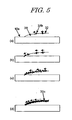
- Low penetrability of the reaction liquid 20 into the recording medium 10 can be obtained by controlling the amount of a surfactant etc., as a penetrant, added to the reaction liquid 20. Meanwhile, Bristow's method is used to evaluate the penetration of the reaction liquid 20 into the recording medium 10. Bristow's method is described in "Method for Testing the Liquid Absorption of Paper and Paper Board", JAPANTAPPI pulp and paper testing method No. 51, in which wetting time Tw, absorption coefficient Ka (mL/m 2 ⁇ ms 1/2 ) and roughness index Vr (mL/ m 2 ) are defined. Since a number of commercially available books describe the method, the detail description of the method is omitted here and only one example of the absorption curves is shown in Fig. 4 .
- the reaction liquid 20 starts to penetrate into the recording medium 10 when the wetting time Tw has elapsed. Accordingly, if the pigment ink 30 is applied before the whole reaction liquid 20 have penetrated into the recording medium 10, it can come into contact with the surface of the reaction liquid that is present on the top surface of the recording medium.
- Td and Tw are in the following relation: Td ⁇ 2.0 ⁇ Tw and preferably Td ⁇ 1.0 x Tw (i.e. before the reaction liquid 20 starts to penetrate into the recording medium) where Td represents the time interval between the application of reaction liquid 20 onto the recording medium 10 and the application of the pigment ink 30 onto the same and Tw the wetting time of the reaction liquid 20.
- V Vr in which V is an amount of transferred liquid and Vr is a roughness index.
- the liquid absorption properties of various types of plain paper can be controlled by controlling the surface tension of the liquid as a main factor, and in commonly used inkjet recording methods, the impact time interval Td between one ink impact on the recording medium and the subsequent ink impact on the same is several milliseconds.
- the reaction liquid preferably has a surface tension of 35 mN/m to 60 mN/m.
- FIG. 3 show a process in which a filmy agglomerate 31c is formed at the interface between the reaction liquid and the pigment ink in contact with each other.
- a filmy agglomerate 31c is formed by agglomerating pigment aggregates 31b immediately after the previous process, being one of the characteristics of the present invention.
- the process in which the filmy agglomeration 31c is formed by the agglomeration of the aggregates 31b will be described in detail later with reference to (a), (b), (c) and (d) of Fig. 5 .
- the reaction liquid 20 it is necessary to allow the reaction liquid 20 to react with a component contained in the pigment ink 30 to cause pigment aggregation.
- the optimal method for this is to add polyvalent metal ions to the reaction liquid to cause pigment aggregation.
- This method may be combined with another method, for example, one in which the pH of the reaction liquid is decreased to utilize an acid precipitation phenomenon or one in which a cationic organic substance is added to the reaction liquid to cause aggregation.
- the polyvalent metal ions 21 contained in the reaction liquid collide with carboxylic acid ions, sulfonic acid ions or phosphoric acid ions in the pigment ink 30 to cause a reaction, thereby decreasing the dispersibility of the pigment, leading to the aggregation of the pigment.
- the polyvalent metal ions 21 are added to the reaction liquid preferably in a concentration higher than the total concentration of the oppositely charged ions present in the pigment ink that can react with the polyvalent metal ions.
- total charge concentration herein used is defined as the number of polyvalent metal ions per unit mass of the reaction liquid or the number of ions of the opposite polarity, such as carboxylic acid ions, sulfonic acid ions or phosphoric acid ions, per unit mass of the pigment ink.
- the carboxylic acid ions, sulfonic acid ions or phosphoric acid ions in the pigment ink 30 bond to the polyvalent metal ions instantaneously, as shown in (b) of Fig. 3 , due to their high collision probability.
- pigment particles 31a which are the pigment particles 31 in the dispersed state with their electric repulsion vanished, are produced.
- aggregates 31b of the pigment particles 31a are formed due to Van der Waals force among the pigment particles 31a, and then the aggregates 31b are agglomerated to form a filmy agglomerate 31c.
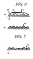
- the reason why the aggregate 31b and the surfactant 32 move on the surface of the reaction liquid 20 is that since the ratio of content of the surfactant 32 in the pigment ink 30 is made high, the surfactant 32 in the pigment ink 30 moves in a oriented manner on the surface of the reaction liquid 20 when it is brought into contact with the reaction liquid 20, and the aggregate 31b moves with the flow of the surfactant. Then, the aggregate 31b stops at the boundary between the reaction liquid 20 and the recording medium 10 and the next aggregate 31b also moves toward the boundary, as shown in (b) of Fig. 5 . And as shown in (c) of Fig. 5 , aggregates 31b formed one after another are oriented toward the surface of the reaction liquid 20. Finally, the density of the aggregates 31b is increased, and the aggregates 31b agglomerate to form a filmy agglomerate 31c on the surface of the reaction liquid 20, as shown in (d) of Fig. 5 .
- the penetrant such as the surfactant 32, and a solvent contained in the pigment ink 30 diffuse gradually into the reaction liquid 20, and with this diffusion, the penetration of the reaction liquid into the recording medium is increased; as a result, the solvent component in the reaction liquid 20 and that of the pigment ink 30 penetrate promptly into the recording medium 10.
- the diffusion of the penetrant and change in the penetration of the reaction liquid is another characteristic of the present invention.
- (e) of Fig. 3 shows the state in which this process has progressed.
- the filmy agglomerate 31c fixes onto the surface of the recording medium 10 (e.g. plain paper consisting of a plurality of fibers) in such a manner as to cover the surface to form an agglomeration film 31d, as shown in (f) of Fig. 3 .
- the recording medium 10 e.g. plain paper consisting of a plurality of fibers
- the solvent component in the reaction liquid 20 and that of the pigment ink 30 penetrate promptly into the recording medium 10, and the filmy agglomerate 31c covers the surface of the recording medium 10 along the ups and downs consisting of the unevenness of the fibers and finally fixes onto the surface as an agglomeration film 31d, as shown in (b) of Fig. 6 .
- the agglomeration film 31d can sometimes be a bridge-like film that covers the surface of the recording medium in such a manner as to cross over the concave portions, or cracks can sometimes be observed in the agglomeration film 31d, which is the characteristics of the agglomeration film 31d.
- (a) of Fig. 8 is an electron micrograph of the surface of plain paper on which nothing is printed.
- the agglomeration film 31d covers the surface of plain paper, as shown in (c) of Fig. 8 . It is apparent from the (c) of Fig. 8 that the agglomeration film 31d covers a plurality of fibers in such a manner as to cross over the fibers and cracks occur in the same agglomeration film 31d.
- one characteristic of the present invention is that the pigment ink 30 is brought into contact with the reaction liquid 20 on the top surface of the recording medium 10.
- a case will be described in which a recording method does not include this, in other words, in which the ink is brought into contact with the reaction liquid somewhere other than the top surface of the recording medium 10. If the pigment ink 30 is brought into contact with the reaction liquid 20 having been impregnated into the recording medium 10, almost all the reaction occurs in the inside of the recording medium 10, and therefore the distribution of the pigment particles becomes larger in the inside of the recording medium than on the surface of the same. This means the resultant image is poor in color development.
- aggregates 31b are not formed on the surface of the reaction liquid, and thus a filmy agglomerate 31c, as a product by the agglomeration of the aggregates 31b, is not formed, either. This also means the resultant image is poor in color development. Moreover, a problem is more likely to occur of strike-through, a phenomenon that the colorant is seen from the reversed side of the recording medium.
- the filmy agglomerate 31c is formed by the agglomeration of the aggregates 31b.
- a case will be described in which a recording method does not include this, in other words, in which the filmy agglomerate 31c is not formed.
- pigment particles have their electric repulsion vanished and even if they aggregate, they do not form a filmy agglomerate and remain in the state of the aggregate 31b.
- the study by the present inventors has revealed that the size of such aggregates 31b is often 10 ⁇ m or less.
- (b) of Fig. 8 is an electron micrograph sowing the state in which the aggregates 31b flow into the space among the fibers of plain paper.
- the electron micrograph seems about the same as that of (a) of Fig. 8 , and it is apparent that the agglomeration film 31d is not formed, unlike in the electron micrograph of (c) of Fig. 8 , and the recorded product is poor in color development.
- an agglomeration film can be formed which covers a plurality of fibers in such a manner as to cross over the same. This agglomeration film can provide excellent color development in the recorded product.
- a filmy agglomerate 31c which is an agglomerate of aggregates 31b, is formed at the interface of the pigment ink and the reaction liquid. Accordingly, with such prior art, the filmy agglomerate 31c cannot be formed. And in the prior art, since the filmy agglomerate 31c is not formed, only aggregates as shown in Fig. 7 or (b) of Fig. 8 are finally formed on the surface of the recording medium, and thus excellent color development cannot be accomplished, unlike the case where an agglomeration film is formed.
- Another characteristic of the present invention is that the penetrability of the reaction liquid 10 is changed by dispersing the penetrant contained into the pigment ink into the reaction liquid. If the penetrant is not dispersed into the reaction liquid 10, the penetrability of the reaction liquid is not changed and the liquid component of the pigment ink 30 is held on the filmy agglomerate 31c. Thus, it takes a long time to dry the printed portion, which causes a problem of low ink fixing properties. This is also true for the case where the pigment ink does not contain a penetrant. In this case, the penetration property of the reaction liquid 20 does not vary, and thus the printed portion holds the liquid component of the pigment ink 30 for a long time, which causes a problem of low ink fixing properties.
- reaction liquid used in the present invention will be described.
- Most preferred examples of chemicals that are contained in the reaction liquid used in the present invention and reactive with the pigment ink used in this invention are polyvalent metal salts.
- Polyvalent metal salts are made up of polyvalent metal ions of two or more valences and anions bonding to the polyvalent metal ions. In the reaction liquid, at least part of such a polyvalent metal salt dissociates into ions.
- polyvalent metal ions include divalent metal ions such as Ca 2+ , Cu 2+ , Ni 2+ , Mg 2+ and Zn 2+ ; and trivalent metal ions such as Fe 3+ and Al 3+ .
- anions include Cl - , NO 3 - and SO 4 2- .
- the total charge concentration of the polyvalent metal ions is preferably two times or more that of the ions of the opposite polarity in the pigment ink.
- the reaction liquid used in this invention may be mixed with additives such as viscosity modifier, pH adjuster, preservative and anti-oxidant depending on the situation; however, the selection and amount of surfactant, which functions as a penetrant, requires great care to control the penetration of the reaction liquid into the recording medium.
- the reaction liquid used in the present invention is preferably colorless; however, it can be light-colored as long as it does not change the color tone of each color ink when mixed therewith. Further, the above described reaction liquid used in the present invention is preferably adjusted so that the viscosity at around 25°C is in the range of 1 to 30 cps.
- the content of pigments in the pigment ink used is in the range of 1 to 20% by mass and preferably 2 to 12% by mass of the total mass of the pigment ink.
- Specific examples of pigments used in the present invention are as follows.
- carbon black is used.
- Preferably used is carbon black produced by, for example, the furnace process or the channel process, whose primary particle size is 15 to 40 m ⁇ m (nm), BET specific surface area is 50 to 300 m 2 /g, DBP oil absorption is 40 to 150 ml/100 g, volatile matter content is 0.5 to 10%, and pH value is 2 to 9.
- carbon black having the above properties include, for example, No. 2300, No. 900, MCF88, No. 33, No. 40, No. 45, No. 52, MA7, MA8, No. 2200B (by Mitsubishi Kasei Corp.), RAVEN 1255 (by Columbia Chemical Corp.), REGAL 400R, REGAL 330R, REGAL 660R, MOGULL (so far by CABOT Corp.), ColorBlack FW1, ColorBlack FW18, ColorBlack S170, ColorBlack S150, Printex 35 and Printex U (by Degussa). Any one of these types of carbon black can be preferably used.
- Examples of yellow pigments include C.I. Pigment Yellow 1, C.I. Pigment Yellow 2, C.I. Pigment Yellow 3, C.I. Pigment Yellow 13, C.I. Pigment Yellow 16 and C.I. Pigment Yellow 83.
- Examples of magenta pigments include: C.I. Pigment Red 5, C.I. Pigment Red 7, C.I. Pigment Red 12, C.I. Pigment Red 48 (Ca), C.I. Pigment Red 48 (Mn), C.I. Pigment Red 57 (Ca), C.I. Pigment Red 112 and C.I. Pigment Red 122.
- Examples of cyan pigments include: C.I. Pigment Blue 1, C.I. Pigment Blue 2, C.I. Pigment Blue 3, C.I.
- Pigment Blue 15 3, C.I. Pigment Blue 16, C.I. Pigment Blue 22, C.I. Vat Blue 4 and C.I. Vat Blue 6. It should be understood that these examples are not intended to limit the present invention. In addition to these examples, self-dispersion type of pigments and newly produced pigments can also be used in the present invention.
- any water-soluble resins can be used.
- water-soluble resins with a weight average molecular weight in the range of 1,000 to 30,000 and more preferably in the range of 3,000 to 15,000.
- Specific examples of such dispersants include block copolymers, random copolymers or graft copolymers made up of at least two or more monomers (at least one of them is a hydrophilic polymerizable monomer) selected from the group consisting of styrene, styrene derivatives, vinylnaphthalene, vinylnaphthalene derivatives, aliphatic alcohol esters of ⁇ , ⁇ -ethylenically unsaturated carboxylic acid, acrylic acid, acrylic acid derivatives, maleic acid, maleic acid derivatives, itaconic acid, itaconic acid derivatives, fumaric acid, fumaric acid derivatives, vinyl acetate, vinyl pyrrolidone, acrylamide and the derivatives thereof, or the salts thereof, or the salts thereof
- Natural resins such as rosin, shellac and starch can also be preferably used. These resins are soluble in a solution of a base in water, that is, they are alkali-soluble resins.
- the amount of the water-soluble resin used as the pigment dispersant is in the range of 0.1 to 5% by mass of the total mass of the pigment ink.
- pigment inks containing the above described pigments are adjusted to be neutral or alkaline. Doing so makes it possible to improve the solubility of water-soluble resins used as the pigment dispersant and provide pigment inks having more excellent long-term shelf stability. Such pigment inks, however, can sometimes cause corrosion in various parts used in inkjet recording apparatus, and thus their pH is preferably kept in the range of 7 to 10.
- pH adjustors used in such pigment inks include various types of organic amines such as diethanolamine and triethanolamine; inorganic alkali agents, for example, hydroxides of alkali metals such as sodium hydroxide, lithium hydroxide and potassium hydroxide; organic acids; and mineral acids.
- organic amines such as diethanolamine and triethanolamine
- inorganic alkali agents for example, hydroxides of alkali metals such as sodium hydroxide, lithium hydroxide and potassium hydroxide
- organic acids such as sodium hydroxide, lithium hydroxide and potassium hydroxide
- mineral acids such as sodium hydroxide, lithium hydroxide and potassium hydroxide
- the above described pigments and water-soluble resins as dispersants are dispersed or dissolved in an aqueous liquid medium.
- Aqueous liquid media suitably used in the pigment inks that contain pigments used in the present invention are solvent mixtures of water and water-soluble organic solvents. And as water, preferably used is not ordinary water that contains various ions, but deionized water.
- Water-soluble organic solvents used as mixtures of water include, for example, alkyl alcohols with 1 to 4 carbon atoms such as methyl alcohol, ethyl alcohol, n-propyl alcohol, isopropyl alcohol, n-butyl alcohol, sec-butyl alcohol and tert-butyl alcohol; amide such as dimethylformamide and dimethylacetamide; ketones or ketoalcohols such as acetone and diacetone alcohol; ethers such as tetrahydrofuran and dioxane; polyalkylene glycols such as polyethylene glycol and polypropylene glycol; alkylene glycols whose alkylene groups have 2 to 6 carbon atoms such as ethylene glycol, propylene glycol, butylene glycol, triethylene glycol, 1,2,6-hexanetriol, thiodiglycol, hexylene glycol and diethylene glycol; glycerol; lower alkyl ethers of polyhydric alcohols such as ethylene
- the amount of the above described water-soluble organic solvents used in the pigment ink is typically in the range of 3 to 50% by mass and preferably in the range of 3 to 40% by mass of the total mass of the pigment ink.
- the amount of water used in the pigment ink is in the range of 10 to 90% by mass and preferably in the range of 30 to 80% by mass of the total mass of the pigment ink.
- anionic surfactants suitably used include any ones commonly used, such as those of the carboxylate type, sulfate ester type, sulfonate type and phosphate ester type.
- the process for preparing pigment inks used in the present invention that contain the above described pigments include a first stage of obtaining a desired dispersion by adding a pigment to an aqueous medium that contains at least a water-soluble resin, as a dispersant, and water, agitating and mixing the mixture, subjecting the mixture to a dispersion process using dispersing means described later, and, if necessary, centrifuging the dispersed mixture; and a second stage of adding a sizing agent and properly selected additives as described above, followed by agitation.
- Bases suitably used for this purpose include, for example, organic amines such as monoethanolamine, diethanolamine, triethanolamine, amine methyl propanol and ammonia; and inorganic bases such as potassium hydroxide and sodium hydroxide.
- aqueous medium that contains a pigment for 30 minutes before subjecting the medium to agitation and dispersion treatment.
- Such a pre-mixing operation is preferable because it improves the wettability on the pigment surface and accelerates the adsorption of a dispersant on the pigment surface.
- any commonly used dispersing machines can be used.
- Specific examples of such dispersing machines include a ball mill, roll mill and sand mill.
- a high-speed type sand mill is preferably used.
- the high-speed type sand mill include, for example, Super Mill, Sand Grinder, Bead Mill, Agitator Mill, Grain Mill, Dyno Mill, Pearl Mill and Cobol Mill (all of these are trade names).
- pigments having an optimum particle size distribution are used in pigment inks to satisfy the requirements for anti-clogging of the inks.
- Means for obtaining pigments having a desired particle size distribution include, for example, decreasing the size of dispersion media of dispersers; increasing the packing ratio of dispersion media; increasing the treatment time; decreasing the ejection speed; sorting with a filter or centrifuge after grinding; and the combination thereof.
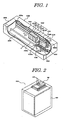
- Fig. 1 is a schematic perspective view of the main part of a liquid ejecting head, as an inkjet recording head of the ejection type in which bubbles are communicated with the atmospheric air at the time of ink ejection, and of one example of inkjet printers, as a liquid ejecting apparatus using the above head, both of which are suitable for the inkjet recording apparatus used in the present invention.
- the inkjet printer includes a carrying device 1030 that intermittently carries paper 1028, as a recording medium, provided in a casing 1008 across the length of the casing in the direction shown by the arrow P in the Fig.; a recording portion 1010 that is moved back and forth along a guide shaft 1014 almost parallel to the direction shown by the arrow S, which is almost perpendicular to the direction P in which the paper 1028 is carried by the carrying device 1030; and a moving driving portion 1006, as driving means, that moves the recording portion 1010 back and forth.
- the moving driving portion 1006 includes pulleys 1026a and 1026b that are spaced at a prescribed interval opposite to each other on a rotating shaft; a belt 1016 wound around the pulleys; roller units 1022a and 1022b; and a motor 1018 that drives forward and backward the belt 1016, which is arranged almost parallel to the roller units and connected to a carriage member 1010a of the recording portion 1010.
- recovering units 1026 for performing ejection recovering treatment for the recording portion 1010 are provided in the position, as the home position of the carriage member 1010a, in such a manner as to be opposite to the array of the ink ejection orifices of the recording portion 1010.
- inkjet cartridges (hereinafter sometimes referred to simply as "cartridge"), 1012Y, 1012M, 1012C and 1012B for pigment inks containing yellow, magenta, cyan and black pigments, respectively and 1012S for a reaction liquid, are provided to the carriage member 1010a in a removable manner.
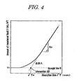
- FIG. 2 shows one example of inkjet cartridges that can be mounted on the above described inkjet recording apparatus.
- a cartridge 1012 as the example is a serial type one and its main part includes an inkjet recording head 100 and a liquid tank 1001 which contains a liquid such as ink.
- the inkjet recording head 100 a number of ejecting orifices 832 are formed and a liquid such as a liquid composition is introduced from the liquid tank 1001 to a common liquid chamber (not shown in the Fig.) of the liquid ejecting head 100 via a liquid feeding passage not shown in the Fig..
- the cartridge 1012 shown in Fig. 2 is a cartridge in which the inkjet recording head 100 and the liquid tank 1001 are integrally formed so that a liquid can be fed into the liquid tank 1001 as need arises.
- the cartridge 1012 may have a structure in which the liquid tank 1001 is exchangeably connected to the liquid ejecting head 100.
- the recording method of the present invention is highly effective when used in inkjet recording heads or recording apparatuses, particularly in those utilizing thermal energy to form liquid droplets and ejecting them to perform recording.
- Typical constructions and principles of such recording heads and apparatuses are disclosed in, for example, U.S. Patent Nos. 4723129 and 4740796 .
- the recording method of the present invention is used in such recording heads and recording apparatuses.
- the method of the present invention is applicable to both on-demand type and continuous type of recording heads and apparatuses; however, its application to the on-demand type of ones is more effective.
- the reason is that in the on-demand type of recording heads and apparatuses, bubble formation in a liquid (ink) and application of a driving signal can be a one-to-one correspondence.
- electrothermal converters arranged for a sheet and liquid passages that hold a liquid (ink) are allowed to generate thermal energy by applying at least one driving signal that corresponds to recording information and provides a rapid temperature increase exceeding the temperature that can cause the film boiling, whereby the film boiling is caused in the heat acting surface of the recording head.
- the liquid (ink) is ejected through an ejecting orifice by the growth and shrinkage of the bubble and forms at least one liquid droplet.
- the driving signal is in a pulse form, because the growth and shrinkage of bubbles can be promptly and properly performed, whereby liquid (ink) ejection excellent in response can be accomplished.
- a plurality of recording heads as disclosed in the above described patent specifications can be used in combination so as to be sufficient for the length, or a recording head may be constructed as an integrally formed unit.
- An exchangeable chip-type recording head which can be electrically connected to the apparatus body and can be provided with ink from the apparatus body only after it is mounted on the apparatus body, or a cartridge-type recording head, which is integral with an ink tank, can also be used.
- Addition of recovery means or spare auxiliary means to the recording head provided for the inkjet recording apparatus used in the present invention is preferable because it further stabilizes the effects of the present invention.
- Examples of such means include capping means, cleaning means, pressurizing or suction means, electrothermal converters or other heating elements, or pre-heating means of the combination thereof for the recording head.
- Conducting a spare ejecting mode, in which ejection different form that for recording is performed, is also effective in realizing stable recording.
- pigment inks of black (K), cyan (C), magenta (M) and yellow (Y) each containing a pigment and an anionic compound were obtained in the manner described below.
- This dispersion was centrifuged (12,000 rpm, 20 minutes), and coarse particles were removed to give a pigment dispersion.
- the ingredients having the composition ratio shown below were mixed using the above dispersion to prepare an ink containing a pigment to be a pigment ink.
- the surface tension of the pigment ink was 34 mN/m.
- Pigment inks C1, M1 and Y1 each containing a pigment were prepared in the same manner as in the preparation of pigment ink K1 except that 10 parts of carbon black (MCF88, by Mitsubishi Kasei Corp.) used in the preparation of pigment ink K1 was replaced by each of the pigments shown in Table 1 below.
- the surface tensions of the prepared pigment inks were 32 mN/m, 31 mN/m and 33 mN/m, respectively.
- the ingredients having the composition ratio shown below were mixed using the above dispersion to prepare an ink containing a pigment to be a pigment ink.
- the surface tension of the pigment ink was 51 mN/m.
- Pigment inks C2, M2 and Y2 each containing a pigment were prepared in the same manner as in the preparation of pigment ink K2 except that 10 parts of carbon black (MCF88, by Mitsubishi Kasei Corp.) used in the preparation of pigment ink K2 was replaced by each of the pigments shown in Table 2 below.
- the surface tensions of the prepared pigment inks were 50 mN/m, 51 mN/m and 48 mN/m, respectively.
- reaction liquid S1 whose pH was adjusted to 3.8.
- reaction liquids S2 to S6 having the respective compositions shown in Table 3 below were also prepared in the same manner as above.
- the wetting times Tw (ms) of the reaction liquids S1 to S5 were measured by Bristow's method.
- absorption coefficient Ka and the roughness index were measured using a dynamic penetration tester (Toyo Seiki Seisaku-Sho, Ltd.).
- the measurements of the wetting times Tw (ms) are shown in Table 4.
- Printed product 1A was prepared using the reaction liquid S1 and the pigment inks K1, C1, M1 and Y1 by applying the reaction liquid S1 onto PB paper (product trade name by Canon Inc.), as plain paper, and then applying pigment inks K1, C1, M1 and Y1 thereon in this order with different time intervals Td of 5, 10, 15 and 20 ms, respectively (Td is the time interval between the provision of the reaction solution S1 and the provision of the pigment inks K1, C1, M1 and Y1), so that each pigment ink came into contact with the reaction liquid S1 and produced a solid print of 1 cm square.
- Td is the time interval between the provision of the reaction solution S1 and the provision of the pigment inks K1, C1, M1 and Y1
- the recording head used in this printing had a recording density of 1,200 dpi and was driven at a driving frequency of 15 kHz. In the head used, the volume of ink ejected per dot was 4 pl. The printing test was conducted under the standardized environmental conditions: 25°C, 55% RH.
- the prepared printed product was good in terms of bleeding and no color-to-color bleeding was observed.
- the optical densities of the printed portions of pigment inks K1, C1, M1 and Y1 were measured with a reflection densitometer, RD-19I (product trade name by Gretag Macbeth). The measurements were 1.2, 1.1, 1.2 and 1.1, respectively.
- Printed product 1B was prepared by applying the pigment inks K1, C1, M1 and Y1 without the reaction liquid S1 onto PB paper (product trade name by Canon Inc.), as plain paper, in the same manner as in example 1.
- PB paper product trade name by Canon Inc.
- the printed product was evaluated in the same manner as in example 1. Although no image deletion was observed, the reflection densities of the printed portions of pigment inks K1, C1, M1 and Y1 were 0.8, 0.7, 0.7 and 0.6, respectively. It is apparent from these measurements that the printed product of example 1 was superior in color development to that of comparative example 1.
- Printed product 1C was obtained in the same manner as in example 1 except that the reaction liquid S1 was replaced by the reaction liquid S6.
- the printed product was evaluated in the same manner as in example 1. Although no image deletion was observed, the reflection densities of the printed portions of pigment inks K1, C1, M1 and Y1 were 0.95, 0.8, 0.9 and 0.8, respectively.
- the printed product 1C was better in bleeding than that of comparative example 1; however, in color development, the printed product of example 1 was apparently superior to that of comparative example 2.
- the surfaces of the printed products 1A, 1B and 1C prepared in example 1 and comparative examples 1 and 2 were observed with a field emission scanning electron microscope, JSM-6700F (product trade name by JEOL), at x 5,000 magnification.
- the amount of the pigment particles present on the surface of each printed product corresponded to the color development of the same.
- the amount of the pigment particles was the largest in the printed product 1A and the pigment particles were fixed even on the top surface of the fibers.
- the ratio of the pigment particles fixed on the fibers was low and there were observed many portions where the fiber surface was exposed.
- Printed product 1D was prepared in the same manner as in example 1 except that the pigment inks K1, C1, M1 and Y1 were replaced by the pigment inks K2, C2, M2 and Y2, respectively.
- the deletion and deformation of the printed image occurred. Even 60 seconds after that, the deformation of the printed image occurred. This indicates that the fixing properties of the ink used in this comparative example were low.
- the time intervals Td were 5, 10, 20, 50, 80, 140 and 180 ms.
- the recording head used in this printing had a recording density of 1,200 dpi and was driven at a driving frequency of 15 kHz. In the head used, the volume of ink ejected per dot was 4 pl.
- the printing test was conducted under the standardized environmental conditions: 25°C, 55% RH.
- Printed products were prepared in the same manner as in example 2 except that the reaction liquid S1 was replaced by the reaction liquid S2 and the time intervals Td were 5, 10, 20, 50, 80 and 140 ms.
- Printed products were prepared in the same manner as in example 2 except that the reaction liquid S1 was replaced by the reaction liquid S3 and the time intervals Td were 5, 10, 20 and 50 ms.
- Printed products were prepared in the same manner as in example 2 except that the reaction liquid S1 was replaced by the reaction liquid S4 and the time intervals Td were 5 and 10 ms.
- a printed product was prepared in the same manner as in example 2 except that the time interval Td was 300 ms.
- Printed products were prepared in the same manner as in example 3 except that the time intervals Td were 180 and 300 ms.
- Printed products were prepared in the same manner as in example 4 except that the time intervals Td were 80, 140, 180 and 300 ms.
- Printed products were prepared in the same manner as in example 5 except that the time intervals Td were 20, 50, 80, 140, 180 and 300 ms.
- Printed products were prepared in the same manner as in example 2 except that the reaction liquid S1 was replaced by the reaction liquid S5 and the time intervals Td were 5, 10, 20, 50, 80, 140, 180 and 300 ms.
- Reflection density was measured with a reflection densitometer for the solid images prepared in examples 2 to 5 and comparative examples 4 to 8. The results are shown in Table 5.
- the evaluation criteria were as follows. A: Reflection density is 1.0 or more. B: Reflection density is 0.85 or more and less than 1.0. C: Reflection density is less than 0.85.
- Table 5 Relationship between time interval Td and image density (common to all the colors) Reaction liquid Time interval Td (ms) 5 10 20 50 80 140 180 300 S1 A A A A A A B B C S2 A A A A B B C C S3 A A A B C C C C S4 A B C C C C C S5 C C C C C C C C C C C C C C C C
- Strike-through was evaluated in the same manner as the evaluation of image density. However, the portion to be measured was the back side of the printed portion of each recording medium. The results are shown in Table 6. The evaluation criteria were as follows. A: Reflection density is less than 0.2. B: Reflection density is 0.2 or more and less than 0.4. C: Reflection density is 0.4 or more and less than 0.6. D: Reflection density is 0.6 or more.
- Table 6 Relationship between time interval Td and strike-through (common to all the colors) Reaction liquid Time interval Td (ms) 5 10 20 50 80 140 180 300 S1 A A A A A B B C S2 A A A A B B D D S3 A A A B D D D S4 A B D D D D D S5 D D D D D D D D D D
- Table 4 in which the physical properties of the reaction liquids S1 to S5 to the recording medium are depicted, and Tables 5 and 6, in which the evaluations of the printed products are depicted, indicate that in examples 2 to 5 where the relationship between the wetting time Tw of the reaction liquids S1 to S5 to the recording medium and the time interval Td between the provision of the pigment ink C1 and the provision of each of the reaction liquids S1 to S5 was Td ⁇ 2.0 ⁇ Tw . And preferably Td ⁇ 1.0 ⁇ Tw , images excellent in image density and strike-through could be obtained and in comparative examples 4 to 8, sufficient optical density was not obtained.
Landscapes
- Chemical & Material Sciences (AREA)
- Inorganic Chemistry (AREA)
- Life Sciences & Earth Sciences (AREA)
- Engineering & Computer Science (AREA)
- Materials Engineering (AREA)
- Wood Science & Technology (AREA)
- Organic Chemistry (AREA)
- Ink Jet Recording Methods And Recording Media Thereof (AREA)
- Inks, Pencil-Leads, Or Crayons (AREA)
- Ink Jet (AREA)
Claims (4)
- Aufzeichnungsverfahren zum Durchführen einer Aufzeichnung auf einem Aufzeichnungsmedium (10) unter Verwendung einer Pigment-Tinte (30), umfassend 10 bis 90 Masse-% Wasser und 1 bis 20 Masse-% Pigment, das 0,05 bis 10 Masse-% eines oberflächenaktiven Stoffs (32) und eine Reaktionsflüssigkeit (20) enthält, die eine höhere Oberflächenspannung als die der Pigment-Tinte (30) aufweist und ein die Pigment-Tinte (30) zu agglomerieren geeignetes, polyvalentes Metallsalz enthält, wobei das Verfahren die Schritte beinhaltet:Aufbringen der Reaktionsflüssigkeit (20) auf dem Aufzeichnungsmedium (10); undIn-Kontakt-bringen der Pigment-Tinte (30) mit der Oberfläche der auf dem Aufzeichnungsmedium (10) vorhandenen Reaktionsflüssigkeit (20), so dass ein filmartiges Agglomerat (31c), zusammengesetzt aus einer Agglomeration von Pigmentaggregaten (31b), hergestellt durch Kontakt zwischen der Reaktionsflüssigkeit (20) und der Pigment-Tinte (30), auf der oberen Oberfläche der auf das Aufzeichnungsmedium (10) aufgebrachten Reaktionsflüssigkeit (20) gebildet wird,wobei die Pigmentaggregate (31b) zusammen mit dem oberflächenaktiven Stoff (32) auf der Oberfläche der Reaktionsflüssigkeit (20) zusammen mit dem oberflächenaktiven Stoff (32) in Richtung einer Grenze zwischen der Reaktionsflüssigkeit (20) und dem Aufzeichnungsmedium (10) migrieren, und durch die Migration der Pigmentaggregate (31b) die Agglomeration der Pigmentaggregate (31b) entlang der Oberfläche der Reaktionsflüssigkeit (20) gebildet wird, und dabei das filmartige Agglomerat (31c) auf der Oberfläche der Reaktionsflüssigkeit (20) gebildet wird.
- Aufzeichnungsverfahren nach Anspruch 1, wobei, nachdem das filmartige Agglomerat (31c) auf der Oberfläche der Reaktionsflüssigkeit (20) gebildet wird, die Lösungsmittelkomponenten der Tinte und die Reaktionsflüssigkeit (20) zum Aufzeichnungsmedium (10) durchdringen, und dadurch das filmartige Agglomerat (31c), das konkave Abschnitte zwischen einer Vielzahl von das Aufzeichnungsmedium (10) aufbauenden Fasern abdeckt, gebildet wird.
- Aufzeichnungsverfahren nach Anspruch 1, wobei, nachdem das filmartige Agglomerat (31c) auf der Oberfläche der Reaktionsflüssigkeit (20) gebildet wird, die Lösungsmittelkomponenten der Tinte und die Reaktionsflüssigkeit (20) zum Aufzeichnungsmedium (10) durchdringen, und dadurch das filmartige Agglomerat (31c), das entlang Höhen und Tiefen einer Vielzahl von das Aufzeichnungsmedium (10) aufbauenden Fasern abdeckt, gebildet wird.
- Aufzeichnungsverfahren nach einem der Ansprüche 1 bis 3, wobei die Pigment-Tinte (30) den oberflächenaktiven Stoff (32) in einer Menge umfasst, die höher ist als die in der Reaktionsflüssigkeit (20).
Applications Claiming Priority (3)
| Application Number | Priority Date | Filing Date | Title |
|---|---|---|---|
| JP2002311468 | 2002-10-25 | ||
| JP2002311468 | 2002-10-25 | ||
| PCT/JP2003/013603 WO2004037546A1 (ja) | 2002-10-25 | 2003-10-24 | インクジェット記録方法および記録物 |
Publications (3)
| Publication Number | Publication Date |
|---|---|
| EP1555137A1 EP1555137A1 (de) | 2005-07-20 |
| EP1555137A4 EP1555137A4 (de) | 2006-04-19 |
| EP1555137B1 true EP1555137B1 (de) | 2008-11-12 |
Family
ID=32171084
Family Applications (1)
| Application Number | Title | Priority Date | Filing Date |
|---|---|---|---|
| EP20030758862 Expired - Lifetime EP1555137B1 (de) | 2002-10-25 | 2003-10-24 | Verfahren zur tintenstrahlaufzeichnung |
Country Status (8)
| Country | Link |
|---|---|
| US (1) | US7396120B2 (de) |
| EP (1) | EP1555137B1 (de) |
| JP (1) | JP2004160996A (de) |
| KR (1) | KR100757160B1 (de) |
| CN (1) | CN100346988C (de) |
| AU (1) | AU2003275642A1 (de) |
| DE (1) | DE60324699D1 (de) |
| WO (1) | WO2004037546A1 (de) |
Families Citing this family (14)
| Publication number | Priority date | Publication date | Assignee | Title |
|---|---|---|---|---|
| JP4989896B2 (ja) * | 2005-03-31 | 2012-08-01 | 富士フイルム株式会社 | インクジェット記録用インクセット、インクジェット記録用インク及びインクジェット画像記録方法 |
| JP5235415B2 (ja) * | 2005-03-31 | 2013-07-10 | 富士フイルム株式会社 | インクジェット記録用インクセット、及びインクジェット画像記録方法 |
| WO2007102621A1 (ja) * | 2006-03-09 | 2007-09-13 | Canon Kabushiki Kaisha | 画像形成方法、画像形成装置、及びインクジェット記録装置 |
| JP4498317B2 (ja) * | 2006-06-13 | 2010-07-07 | キヤノン株式会社 | 画像形成方法および画像形成装置 |
| US7973097B2 (en) | 2007-04-24 | 2011-07-05 | Canon Kabushiki Kaisha | Ink jet pigment ink and ink set |
| JP5274083B2 (ja) * | 2008-04-08 | 2013-08-28 | 京セラドキュメントソリューションズ株式会社 | インクジェット記録方法及びインクジェット記録装置 |
| EP2285917B1 (de) * | 2008-05-22 | 2012-08-01 | E. I. du Pont de Nemours and Company | Fixiertinten für tintenstrahltinten |
| JP5344871B2 (ja) * | 2008-08-22 | 2013-11-20 | 富士フイルム株式会社 | インクジェット記録方法 |
| US8220913B2 (en) * | 2008-08-28 | 2012-07-17 | Fujifilm Corporation | Ink-jet recording method |
| WO2011093896A1 (en) * | 2010-01-31 | 2011-08-04 | Hewlett-Packard Development Company, L.P. | Paper with surface treatment |
| JP6050998B2 (ja) * | 2012-09-28 | 2016-12-21 | 株式会社Screenホールディングス | 画像形成装置および画像形成方法 |
| EP3403840B1 (de) * | 2016-01-15 | 2023-04-12 | Toyo Ink SC Holdings Co., Ltd. | Vorbehandlungslösung, tintensatz und verfahren zur herstellung von drucksachen |
| JP6776623B2 (ja) * | 2016-05-30 | 2020-10-28 | ブラザー工業株式会社 | インクセット及び記録方法 |
| WO2024153482A1 (en) | 2023-01-16 | 2024-07-25 | Agfa Nv | Method of ink jet recording |
Family Cites Families (29)
| Publication number | Priority date | Publication date | Assignee | Title |
|---|---|---|---|---|
| CA1127227A (en) | 1977-10-03 | 1982-07-06 | Ichiro Endo | Liquid jet recording process and apparatus therefor |
| US4330787A (en) | 1978-10-31 | 1982-05-18 | Canon Kabushiki Kaisha | Liquid jet recording device |
| JPS5565269A (en) | 1978-11-10 | 1980-05-16 | Seiko Epson Corp | Quick drying ink for ink jet recording |
| US4345262A (en) | 1979-02-19 | 1982-08-17 | Canon Kabushiki Kaisha | Ink jet recording method |
| US4463359A (en) | 1979-04-02 | 1984-07-31 | Canon Kabushiki Kaisha | Droplet generating method and apparatus thereof |
| US4313124A (en) | 1979-05-18 | 1982-01-26 | Canon Kabushiki Kaisha | Liquid jet recording process and liquid jet recording head |
| JPS5689595A (en) | 1979-12-21 | 1981-07-20 | Canon Inc | Ink-jet recording method |
| JPH019279Y2 (de) | 1980-08-21 | 1989-03-14 | ||
| US4558333A (en) | 1981-07-09 | 1985-12-10 | Canon Kabushiki Kaisha | Liquid jet recording head |
| JPS59123670A (ja) | 1982-12-28 | 1984-07-17 | Canon Inc | インクジエツトヘツド |
| JPS59138461A (ja) | 1983-01-28 | 1984-08-08 | Canon Inc | 液体噴射記録装置 |
| JPS6159911A (ja) | 1984-08-30 | 1986-03-27 | Nec Corp | 切換スイツチ回路 |
| JPS6159914A (ja) | 1984-08-31 | 1986-03-27 | Fujitsu Ltd | デイジタル圧縮装置 |
| JPS6159912A (ja) | 1984-08-31 | 1986-03-27 | Fujitsu Ltd | Ttl回路 |
| JP2697767B2 (ja) | 1986-07-23 | 1998-01-14 | 浜松ホトニクス 株式会社 | 放射線撮像装置 |
| JPS649279A (en) | 1987-06-30 | 1989-01-12 | Ricoh Kk | Method of ink jet recording |
| JPH058617Y2 (de) | 1987-07-06 | 1993-03-03 | ||
| JP2676699B2 (ja) | 1987-09-03 | 1997-11-17 | 株式会社リコー | インクジェット記録方法 |
| JPH0163185U (de) | 1987-10-14 | 1989-04-24 | ||
| EP0534634A1 (de) | 1991-09-23 | 1993-03-31 | Hewlett-Packard Company | Verfahren und Zusammensetzungen zur Herstellung von stabilen, wasserfesten bedrückten Bildern |
| SG49550A1 (en) * | 1994-05-31 | 1998-06-15 | Canon Kk | Toner for developing electrostatic images and image forming method |
| JP3550637B2 (ja) * | 1996-09-27 | 2004-08-04 | セイコーエプソン株式会社 | インクジェット記録方法 |
| WO1998030398A1 (en) | 1997-01-14 | 1998-07-16 | Seiko Epson Corporation | Ink jet recording method using two solutions |
| US6238045B1 (en) | 1997-02-18 | 2001-05-29 | Canon Kabushiki Kaisha | Image forming method, ink-jet recording method and instruments used in such methods |
| JP3697046B2 (ja) * | 1997-02-19 | 2005-09-21 | キヤノン株式会社 | 画像形成方法および画像形成装置 |
| US6494569B2 (en) * | 2000-06-21 | 2002-12-17 | Canon Kabushiki Kaisha | Ink-jet printing method |
| US6481819B2 (en) * | 2000-07-10 | 2002-11-19 | Canon Kabushiki Kaisha | Ink jet recording head and recording apparatus having recording element substrates with different liquid ejection systems |
| JP4111104B2 (ja) | 2003-08-28 | 2008-07-02 | セイコーエプソン株式会社 | 反応液、インクセット及びインクジェット記録方法 |
| JP2005074656A (ja) | 2003-08-28 | 2005-03-24 | Seiko Epson Corp | 反応液、インクセット及びインクジェット記録方法 |
-
2003
- 2003-10-24 WO PCT/JP2003/013603 patent/WO2004037546A1/ja not_active Ceased
- 2003-10-24 EP EP20030758862 patent/EP1555137B1/de not_active Expired - Lifetime
- 2003-10-24 DE DE60324699T patent/DE60324699D1/de not_active Expired - Lifetime
- 2003-10-24 US US10/531,228 patent/US7396120B2/en not_active Expired - Lifetime
- 2003-10-24 JP JP2003364566A patent/JP2004160996A/ja active Pending
- 2003-10-24 CN CNB2003801046746A patent/CN100346988C/zh not_active Expired - Fee Related
- 2003-10-24 KR KR1020057006980A patent/KR100757160B1/ko not_active Expired - Fee Related
- 2003-10-24 AU AU2003275642A patent/AU2003275642A1/en not_active Abandoned
Also Published As
| Publication number | Publication date |
|---|---|
| CN1720146A (zh) | 2006-01-11 |
| DE60324699D1 (de) | 2008-12-24 |
| US7396120B2 (en) | 2008-07-08 |
| US20060012627A1 (en) | 2006-01-19 |
| EP1555137A1 (de) | 2005-07-20 |
| KR100757160B1 (ko) | 2007-09-07 |
| EP1555137A4 (de) | 2006-04-19 |
| JP2004160996A (ja) | 2004-06-10 |
| WO2004037546A1 (ja) | 2004-05-06 |
| CN100346988C (zh) | 2007-11-07 |
| AU2003275642A1 (en) | 2004-05-13 |
| KR20050060102A (ko) | 2005-06-21 |
Similar Documents
| Publication | Publication Date | Title |
|---|---|---|
| US6517199B1 (en) | Liquid composition, ink set, colored area formation on recording medium, and ink-jet recording apparatus | |
| US8007097B2 (en) | Water-based ink, ink jet recording method, ink cartridge, recording unit, ink jet recording apparatus, and image forming method | |
| EP1762598B1 (de) | Wässrige tinte, wässriger tintensatz, tintenpatrone, tintenstrahlaufzeichner, tintenstrahlaufzeichnungsverfahren und bilderzeugungsverfahren | |
| US6460989B1 (en) | Ink set, formation of colored area on recording medium, and ink-jet recording apparatus | |
| EP1764397B1 (de) | Cyantinte und tintenkombination | |
| US6299675B1 (en) | Printing method, image forming process, ink, ink set, recording unit, image forming apparatus and print | |
| JPH0881611A (ja) | 液体組成物、インクセット及びこれを用いた画像形成方法と装置 | |
| EP1555137B1 (de) | Verfahren zur tintenstrahlaufzeichnung | |
| JPH0872393A (ja) | 液体組成物、インクセット、及びこれらを用いた画像形成方法と装置 | |
| JP2001199151A (ja) | 液体組成物、インクセット、被記録媒体への着色部の形成方法及びインクジェット記録装置 | |
| JPH0820720A (ja) | 液体組成物、インクセット及びこれを用いた画像形成方法 | |
| JP3461202B2 (ja) | 液体組成物、インクセット及びインクジェット記録方法 | |
| JP4136814B2 (ja) | インクセット及びインクジェット記録方法 | |
| US7226157B2 (en) | Ink-jet recording process | |
| JP2006169345A (ja) | インクジェット用顔料インク、インクセット、画像形成方法及び画像記録装置 | |
| JP3817388B2 (ja) | インクジェット記録用インクセット、印刷方法、およびインクジェット記録用淡インク | |
| JPH0880664A (ja) | 液体組成物、インクセット、及びこれらを用いた画像形成方法と装置 | |
| JP2005305687A (ja) | インクジェット記録方法 | |
| JP4717627B2 (ja) | インクジェット記録方法およびインクジェット記録装置 | |
| JP2004255870A (ja) | インクセット、画像記録方法及び画像記録装置 | |
| JP2005153382A (ja) | インクジェット記録方法およびインクジェット記録装置 | |
| JP4428929B2 (ja) | インクジェット記録方法 | |
| JP2004142291A (ja) | インクジェット記録方法 | |
| JPH0820162A (ja) | 液体組成物、インクセット及びこれを用いた画像形成方法 | |
| JP4040584B2 (ja) | インクジェット記録方法 |
Legal Events
| Date | Code | Title | Description |
|---|---|---|---|
| PUAI | Public reference made under article 153(3) epc to a published international application that has entered the european phase |
Free format text: ORIGINAL CODE: 0009012 |
|
| 17P | Request for examination filed |
Effective date: 20050420 |
|
| AK | Designated contracting states |
Kind code of ref document: A1 Designated state(s): AT BE BG CH CY CZ DE DK EE ES FI FR GB GR HU IE IT LI LU MC NL PT RO SE SI SK TR |
|
| AX | Request for extension of the european patent |
Extension state: AL LT LV MK |
|
| DAX | Request for extension of the european patent (deleted) | ||
| RBV | Designated contracting states (corrected) |
Designated state(s): DE FR GB IT |
|
| A4 | Supplementary search report drawn up and despatched |
Effective date: 20060302 |
|
| 17Q | First examination report despatched |
Effective date: 20060811 |
|
| GRAP | Despatch of communication of intention to grant a patent |
Free format text: ORIGINAL CODE: EPIDOSNIGR1 |
|
| RIC1 | Information provided on ipc code assigned before grant |
Ipc: B41M 5/00 20060101AFI20080418BHEP |
|
| RTI1 | Title (correction) |
Free format text: METHOD OF INK-JET RECORDING |
|
| GRAS | Grant fee paid |
Free format text: ORIGINAL CODE: EPIDOSNIGR3 |
|
| GRAA | (expected) grant |
Free format text: ORIGINAL CODE: 0009210 |
|
| AK | Designated contracting states |
Kind code of ref document: B1 Designated state(s): DE FR GB IT |
|
| REG | Reference to a national code |
Ref country code: GB Ref legal event code: FG4D |
|
| REF | Corresponds to: |
Ref document number: 60324699 Country of ref document: DE Date of ref document: 20081224 Kind code of ref document: P |
|
| PLBE | No opposition filed within time limit |
Free format text: ORIGINAL CODE: 0009261 |
|
| STAA | Information on the status of an ep patent application or granted ep patent |
Free format text: STATUS: NO OPPOSITION FILED WITHIN TIME LIMIT |
|
| 26N | No opposition filed |
Effective date: 20090813 |
|
| REG | Reference to a national code |
Ref country code: FR Ref legal event code: PLFP Year of fee payment: 13 |
|
| PGFP | Annual fee paid to national office [announced via postgrant information from national office to epo] |
Ref country code: IT Payment date: 20151005 Year of fee payment: 13 |
|
| PGFP | Annual fee paid to national office [announced via postgrant information from national office to epo] |
Ref country code: FR Payment date: 20151028 Year of fee payment: 13 |
|
| REG | Reference to a national code |
Ref country code: FR Ref legal event code: ST Effective date: 20170630 |
|
| PG25 | Lapsed in a contracting state [announced via postgrant information from national office to epo] |
Ref country code: FR Free format text: LAPSE BECAUSE OF NON-PAYMENT OF DUE FEES Effective date: 20161102 |
|
| PG25 | Lapsed in a contracting state [announced via postgrant information from national office to epo] |
Ref country code: IT Free format text: LAPSE BECAUSE OF NON-PAYMENT OF DUE FEES Effective date: 20161024 |
|
| PGFP | Annual fee paid to national office [announced via postgrant information from national office to epo] |
Ref country code: GB Payment date: 20181031 Year of fee payment: 16 |
|
| PGFP | Annual fee paid to national office [announced via postgrant information from national office to epo] |
Ref country code: DE Payment date: 20181228 Year of fee payment: 16 |
|
| REG | Reference to a national code |
Ref country code: DE Ref legal event code: R119 Ref document number: 60324699 Country of ref document: DE |
|
| PG25 | Lapsed in a contracting state [announced via postgrant information from national office to epo] |
Ref country code: DE Free format text: LAPSE BECAUSE OF NON-PAYMENT OF DUE FEES Effective date: 20200501 |
|
| GBPC | Gb: european patent ceased through non-payment of renewal fee |
Effective date: 20191024 |
|
| PG25 | Lapsed in a contracting state [announced via postgrant information from national office to epo] |
Ref country code: GB Free format text: LAPSE BECAUSE OF NON-PAYMENT OF DUE FEES Effective date: 20191024 |