EP1555136A1 - Alimentation de supports en forme de feuille - Google Patents
Alimentation de supports en forme de feuille Download PDFInfo
- Publication number
- EP1555136A1 EP1555136A1 EP04017404A EP04017404A EP1555136A1 EP 1555136 A1 EP1555136 A1 EP 1555136A1 EP 04017404 A EP04017404 A EP 04017404A EP 04017404 A EP04017404 A EP 04017404A EP 1555136 A1 EP1555136 A1 EP 1555136A1
- Authority
- EP
- European Patent Office
- Prior art keywords
- feature
- supporting surface
- sheet
- media
- along
- Prior art date
- Legal status (The legal status is an assumption and is not a legal conclusion. Google has not performed a legal analysis and makes no representation as to the accuracy of the status listed.)
- Granted
Links
- 238000000926 separation method Methods 0.000 description 5
- 230000000694 effects Effects 0.000 description 3
- 230000005484 gravity Effects 0.000 description 2
- 239000013536 elastomeric material Substances 0.000 description 1
- 230000000284 resting effect Effects 0.000 description 1
Images


Classifications
-
- B—PERFORMING OPERATIONS; TRANSPORTING
- B65—CONVEYING; PACKING; STORING; HANDLING THIN OR FILAMENTARY MATERIAL
- B65H—HANDLING THIN OR FILAMENTARY MATERIAL, e.g. SHEETS, WEBS, CABLES
- B65H3/00—Separating articles from piles
- B65H3/46—Supplementary devices or measures to assist separation or prevent double feed
- B65H3/52—Friction retainers acting on under or rear side of article being separated
- B65H3/5246—Driven retainers, i.e. the motion thereof being provided by a dedicated drive
Definitions
- next-to-top sheets are separated from the top sheet by driving the sheets across an elastomeric pad positioned at the front of the media input tray.
- This pad is often referred to as a separator pad because it's function is to separate the top sheet in the stack from next-to-top sheets in the stack so that only the top sheet moves into the printer.
- the separator pad is lifted against the pick roller at the beginning of the pick cycle and then quickly lowered to momentarily increase the separating effect of the pad.
- the active separator pad design used in the Deskjet® 5150 works well when media sheets are picked from a horizontal stack, where the separator pad need overcome only the friction force between sheets. If this active separator pad design is used when sheets are picked from a vertically oriented stack, however, gravity can pull multiple sheets into the media path as soon as the pad is moved away from the pick roller, resulting in more than one sheet being fed into the printer.
- Fig. 1 is a perspective view of the outside of a vertical feed inkjet printer constructed according to one embodiment of the invention.
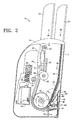
- Figs. 2 and 3 are side elevation and partial section views of the vertical feed inkjet printer shown in Fig. 1.
- Figs. 4-6 are detail views of the sheet feed area of the printer shown in Figs. 1-3.
- Fig. 7 is a perspective of the separator pads and pick roller of the printer of Figs. 1-3.
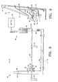
- Fig. 8 is a front elevation view of a separator pad actuator used in the printer of Figs. 1-3.
- Fig. 9 is a side elevation and partial section view taken along the line 9-9 in Fig. 8.
- Embodiments of the present invention were developed in an effort to adapt an active separator pad design from a conventional horizontal feed printer to a new vertical feed printer. Embodiments of the invention will be described with reference to the vertical feed inkjet printer shown in Figs. 1-3. The invention, however, is not limited to use with inkjet printers or vertical feed printers. Embodiments of the invention may be implemented in other printers or other sheet media processing devices. While the invention is not limited to use with vertical feed printers, it is expected that various embodiments of the invention will be particularly useful in such printers.
- Fig. 1 illustrates an inkjet printer 10.
- Figs. 2 and 3 are side elevation and partial section views of printer 10.
- printer 10 includes a an input sheet media tray 12 and an output sheet media tray 14 supported by a housing 16.
- Input tray 12 includes a substantially vertical sheet media supporting surface 17.
- substantially vertical as used in this document means within 5 degrees of true vertical.
- Printer 10 includes a chassis 18 that supports the operative components of printer 10. Chassis 18 represents generally those parts of printer housing 16 along with other structurally stable elements in printer 10 that support the operative components of printer 10.
- a printhead carriage 20 is driven back and forth along a guide rail 22 mounted to chassis 18. Any suitable drive mechanism may be used to move carriage 20.
- Carriage 20 has stalls for holding one or more printheads 26.
- Printheads 26 are also commonly referred to as print cartridges or ink cartridges.
- Each printhead 26 is positioned along a media path 28 such that each sheet of print media 30 passes directly by printhead 26 at a print zone 32.
- the portion 34 of each printhead 26 that faces media sheet 30 includes an array of nozzles through which drops of ink are ejected onto media sheet 30.
- An electronic printer controller 36 receives print data from a computer, scanner, digital camera or other image generating device. Controller 36 controls the movement of carriage 20 back and forth across media sheet 30 and the advance of media sheet 30 along media path 28. Printer controller 36 is also electrically connected to printhead 26 through, for example, a flexible ribbon cable 38. As carriage 20 carries printhead 26 across media sheet 30, printer controller 36 selectively activates ink ejection elements in printhead 26 according to the print data to eject ink drops through the nozzles onto media sheet 30. By combining the movement of carriage 20 across media sheet 30 with the movement of sheet 30 along media path 28, controller 36 causes printhead 26 to eject ink onto media sheet 30 to form the desired print image.
- Figs. 4-6 are detail views of the sheet feed area of printer 10.
- the position of feed area components shown in Figs. 2 and 3 correspond to those shown in the detail views of Figs. 5 and 6, respectively.
- Figs. 2-3 and 5-6 show top sheet 30 "picked" from a stack 40 of media sheets in tray 12 and fed along media path 28.
- a pick roller 42 mounted on a roller shaft 44 is driven clockwise by a motor 46 at the direction of controller 36 to grab top sheet 30 and feed it along media path 28 toward feed rollers 48 (motor 46 is shown in Figs. 7 and 8).
- Each feed roller 48 bears against an idler arm 50 to form a nip that moves sheet 30 along toward output rollers 52.
- Each output roller 52 bears against an idler roller 54 to form a nip that moves sheet 30 into output tray 14.
- Fig. 4 is a detail view showing feed area components when printer 10 is at rest, before a pick cycle.
- Fig. 7 is a detail view showing a lower paper guide 56 and pick roller 42 on shaft 44.
- lower paper guide 56 is mounted to chassis 18 below input tray 12. The leading edges of sheets 30 in stack 40 rest along an upper surface 58 of lower paper guide 56. Upper surface 58 is also referred to as shelf 58.
- Separator pads 60, 62 and 64 are mounted to a sloping surface 66 on lower paper guide 56 immediately below shelf 58.
- Separator pads 60, 62 and 64 typically formed from an elastomeric material, represent generally any comparatively soft structural feature with a suitably high coefficient of friction that protrudes from sloping surface 66 or otherwise extends into media path 28 downstream from tray 12 to help separate next-to-top sheets carried along with top sheet 30.
- Separator pad 60 is mounted on a hinge 68 so it can move in and out of media path 28, as described below. Separator pads 62 and 64 are stationary.
- a pair of stack return “kickers" 70 are hinged to lower paper guide 56.
- Figs. 2-6 the lower part of stack 40 is supported in input tray 12 on a hinged pressure plate 72.
- pressure plate 72 swings out to press stack 40 against pick roller 42 as best seen by comparing Figs. 4 and 5.
- separator pad 60 is pressed against pick roller 42 as shown in Figs. 2 and 5.
- Pick roller 42 is rotated (clockwise in the figures) to draw top sheet 30 into media path 28, usually along with several next-to-top sheets.
- Separator pad 60 is then withdrawn from pick roller 42, pressure plate 72 collapses and top sheet 30 continues along media path 28 toward feed roller 48 while any next-to-top sheets drawn into media path 28 remain stuck on separator pads 62 and 64, as shown in Figs. 2 and 6.
- the force of pick roller 42 on top sheet 30 is sufficient to overcome the resistance of separator pads 60, 62 and 64 while any next-to-top sheets will be stopped, initially by all three pads 60, 62 and 64 and then by pads 62 and 64 after pad 60 is withdrawn.
- pick roller 42 may still be turning after the trailing edge of top sheet 30 has cleared the separation area.
- stationary separator pads 62 and 64 are positioned far enough back from pick roller 42 so that an exposed and still turning pick roller 42 does not grab the next-to-top sheet lying on pads 62 and 64.
- separator pads 62 and 64 are constructed as elongated strips that extend below pad 60 to ensure that pads 62 and 64 extend past the area on pad 60 where top sheet 30 is separated from next-to-top sheets.
- pad 60 and pads 62 and 64 are positioned relative to one another such that pad 60 will be slightly higher than pads 62 and 64 when pad 60 is pressed against pick roller 42 and slightly lower than pads 62 and 64 when pad 60 is withdrawn from pick roller 42.
- pad 60 lifts top sheet 30 and, perhaps, one or two next-to-top sheets to momentarily reduce the separating effect of pads 62 and 64 and allow top sheet 30 to move more easily into the nip 74 between pad 60 and pick roller 42.
- pad 60 When pad 60 is withdrawn, pad 60 no longer retards the progress of top sheet 30 as pick roller 42 continues to move top sheet 30 over pads 62 and 64 along media path 28 toward feed roller 48.
- kickers 70 are rotated up, as indicated by the phantom lines in Fig. 4, to push stack 40 back into position for the start of the next pick cycle. (Kickers 70 are also shown in Fig. 7.) Kickers 70 are then withdrawn to the resting position, indicated by the solid lines in Fig. 4.
- Figs. 8 and 9 illustrate one embodiment of an actuator 76 for moving separator pad 60, kickers 70 and pressure plate 72.
- Fig. 9 is a side elevation and partial section view taken along the line 9-9 in Fig. 8. Some of the components of actuator 76 are also visible in Figs. 2-6. A similar actuator is used in Hewlett-Packard Company's Deskjet® 5150 and other horizontal feed inkjet printer models. Referring to Figs. 8 and 9, separator pad 60 and kickers 70 move at the urging of motor 46 acting through actuator 76.
- Actuator 76 includes a cam 78, a linkage 80 for moving separator pad 60, a linkage 82 for moving kickers 70, and a linkage 84 for moving pressure plate 72.
- Separator pad linkage 80 includes a pick lever 88, a separator pad lift lever 90 and a separator pad lift rod 92.
- Kicker linkage 82 includes an L-shaped pivot rod 94 that transfers the rotation of cam 78 to kickers 70.
- Pressure plate linkage 84 includes pick lever 88 and a pressure plate lift lever 96.
- cam 78 is rotated to release pick lever 88, as shown in Fig. 2.
- pick lever 88 pivots forward (counter-clockwise in Figs. 2 and 9) at the urging of biasing spring 98 to allow separator pad lift lever 90 to pivot forward (clockwise in Figs. 2 and 9) and to pivot pressure plate lift lever 96 forward (clockwise in Figs. 2 and 9).
- Pad lift lever 90 pushes lift rod 92 up to move separator pad 60 against pick roller 42.
- a biasing spring 100 moves separator pad 60 against pick roller 42.
- Pressure plate lift lever 96 pushes the bottom of pressure plate 72 out to move stack 40 against pick roller 42.
- cam 78 is rotated against pick lever 88 to move separator pad 60 away from pick roller 42.
- Pick lever 88 pivots backward (clockwise in Fig. 3) to pivot separator pad lift lever 90 backward (clockwise in Fig. 3) and to release pressure plate lift lever 96.
- Pad lift lever 90 pulls lift rod 92 down to move separator pad 60 away from pick roller 42.
- cam 78 continues to rotate, it engages and rotates pivot rod 94 to swing kickers 70 up against stack 40, as shown by the phantom lines in Fig. 4, and put stack 40 back into position for the start of the next pick cycle.
- Carriage 20 and printhead 26 along with other hardware components necessary to deliver ink to the print media are referred to collectively as a print engine.
- Rollers 42, 48 and 50 along with other hardware components necessary to transport print media through printer 10 are referred to collectively as a pick/feed mechanism.
- Controller 36 includes the programming, processor and associated memory and electronic circuitry necessary to control the print engine, the pick/feed mechanism, and the other operative components of printer 10.
Landscapes
- Engineering & Computer Science (AREA)
- Mechanical Engineering (AREA)
- Sheets, Magazines, And Separation Thereof (AREA)
Applications Claiming Priority (2)
| Application Number | Priority Date | Filing Date | Title |
|---|---|---|---|
| US10/758,057 US7100914B2 (en) | 2004-01-15 | 2004-01-15 | Sheet media input |
| US758057 | 2004-01-15 |
Publications (2)
| Publication Number | Publication Date |
|---|---|
| EP1555136A1 true EP1555136A1 (fr) | 2005-07-20 |
| EP1555136B1 EP1555136B1 (fr) | 2009-12-09 |
Family
ID=34620688
Family Applications (1)
| Application Number | Title | Priority Date | Filing Date |
|---|---|---|---|
| EP04017404A Expired - Lifetime EP1555136B1 (fr) | 2004-01-15 | 2004-07-22 | Alimentation de supports en forme de feuille |
Country Status (4)
| Country | Link |
|---|---|
| US (1) | US7100914B2 (fr) |
| EP (1) | EP1555136B1 (fr) |
| JP (1) | JP3806132B2 (fr) |
| DE (1) | DE602004024496D1 (fr) |
Families Citing this family (13)
| Publication number | Priority date | Publication date | Assignee | Title |
|---|---|---|---|---|
| JP3960322B2 (ja) * | 2004-06-25 | 2007-08-15 | ブラザー工業株式会社 | 被記録シート供給装置及びファクシミリ装置 |
| JP4478590B2 (ja) * | 2005-02-03 | 2010-06-09 | キヤノン株式会社 | シート給送装置及び画像読取装置及び画像形成装置 |
| JP4946719B2 (ja) * | 2007-08-14 | 2012-06-06 | セイコーエプソン株式会社 | 被記録材の分離装置及び記録装置 |
| JP4711004B2 (ja) * | 2009-03-31 | 2011-06-29 | ブラザー工業株式会社 | 給紙装置 |
| JP5495681B2 (ja) * | 2009-09-07 | 2014-05-21 | キヤノン株式会社 | シート給送装置、画像読取装置及び画像形成装置 |
| US8215633B2 (en) | 2010-08-30 | 2012-07-10 | Eastman Kodak Company | Media stopper method for a printing system |
| US8328183B2 (en) | 2010-08-30 | 2012-12-11 | Eastman Kodak Company | Media stopper for a printing system |
| US8215631B2 (en) | 2010-08-30 | 2012-07-10 | Eastman Kodak Company | Pick roller retraction in a carriage printer |
| US8215632B2 (en) | 2010-08-30 | 2012-07-10 | Eastman Kodak Company | Pick roller retraction method in a carriage printer |
| US8449107B2 (en) * | 2010-10-04 | 2013-05-28 | Seiko Epson Corporation | Recording apparatus |
| US8910932B2 (en) | 2011-06-30 | 2014-12-16 | Hewlett-Packard Development Company, L.P. | Separator assembly for use with printers |
| WO2017131785A1 (fr) | 2016-01-29 | 2017-08-03 | Hewlett-Packard Development Company, L.P. | Dispositif comprenant un séparateur |
| WO2019143357A1 (fr) | 2018-01-19 | 2019-07-25 | Hewlett-Packard Development Company, L.P. | Élément culbuteur à ressort |
Citations (4)
| Publication number | Priority date | Publication date | Assignee | Title |
|---|---|---|---|---|
| JPH0466436A (ja) * | 1990-07-09 | 1992-03-02 | Konica Corp | 原稿給紙装置 |
| JPH11208914A (ja) * | 1998-01-20 | 1999-08-03 | Brother Ind Ltd | 自動給紙装置 |
| JP2001019194A (ja) * | 1999-07-05 | 2001-01-23 | Canon Inc | シート給送装置及び記録装置及びシート給送装置の給紙方法 |
| US6382621B1 (en) * | 1998-11-04 | 2002-05-07 | Canon Kabushiki Kaisha | Paper feeder with movable separation slope surface and image forming apparatus equipped therewith |
Family Cites Families (11)
| Publication number | Priority date | Publication date | Assignee | Title |
|---|---|---|---|---|
| JP3446347B2 (ja) | 1994-10-18 | 2003-09-16 | 富士ゼロックス株式会社 | 給紙装置 |
| CH690854A5 (fr) * | 1996-02-28 | 2001-02-15 | Olivetti Lexikon Spa | Procédé et dispositif d'introduction de feuilles. |
| JP3731260B2 (ja) * | 1996-09-06 | 2006-01-05 | ブラザー工業株式会社 | 給紙装置及びそれを備える画像記録機 |
| US5882004A (en) * | 1996-09-18 | 1999-03-16 | Hewlett-Packard Co. | Automatic sheet feeding mechanism |
| US5938355A (en) * | 1996-10-14 | 1999-08-17 | Brother Kogyo Kabushiki Kaisha | Sheet feeder and printer fitted with sheet feeder |
| JPH11310341A (ja) * | 1998-04-28 | 1999-11-09 | Oki Data Corp | プリンタの給紙装置及び給紙方法 |
| JP3576958B2 (ja) * | 2000-10-31 | 2004-10-13 | キヤノン株式会社 | 給紙装置及びこれを備えた画像形成装置 |
| JP2002173239A (ja) * | 2000-12-07 | 2002-06-21 | Brother Ind Ltd | 給紙装置 |
| JP3738743B2 (ja) * | 2002-03-29 | 2006-01-25 | ブラザー工業株式会社 | 給紙装置及びこれを備えた画像形成装置 |
| JP3741068B2 (ja) | 2002-03-29 | 2006-02-01 | ブラザー工業株式会社 | 給紙装置及びこれを備えた画像形成装置 |
| US6663098B2 (en) * | 2002-04-25 | 2003-12-16 | Hewlett-Packard Development Company, L.P. | Compound kicker in media handling system |
-
2004
- 2004-01-15 US US10/758,057 patent/US7100914B2/en not_active Expired - Fee Related
- 2004-07-22 EP EP04017404A patent/EP1555136B1/fr not_active Expired - Lifetime
- 2004-07-22 DE DE602004024496T patent/DE602004024496D1/de not_active Expired - Lifetime
-
2005
- 2005-01-07 JP JP2005002283A patent/JP3806132B2/ja not_active Expired - Fee Related
Patent Citations (4)
| Publication number | Priority date | Publication date | Assignee | Title |
|---|---|---|---|---|
| JPH0466436A (ja) * | 1990-07-09 | 1992-03-02 | Konica Corp | 原稿給紙装置 |
| JPH11208914A (ja) * | 1998-01-20 | 1999-08-03 | Brother Ind Ltd | 自動給紙装置 |
| US6382621B1 (en) * | 1998-11-04 | 2002-05-07 | Canon Kabushiki Kaisha | Paper feeder with movable separation slope surface and image forming apparatus equipped therewith |
| JP2001019194A (ja) * | 1999-07-05 | 2001-01-23 | Canon Inc | シート給送装置及び記録装置及びシート給送装置の給紙方法 |
Non-Patent Citations (3)
| Title |
|---|
| PATENT ABSTRACTS OF JAPAN vol. 016, no. 270 (M - 1266) 17 June 1992 (1992-06-17) * |
| PATENT ABSTRACTS OF JAPAN vol. 1999, no. 13 30 November 1999 (1999-11-30) * |
| PATENT ABSTRACTS OF JAPAN vol. 2000, no. 16 8 May 2001 (2001-05-08) * |
Also Published As
| Publication number | Publication date |
|---|---|
| US20050156372A1 (en) | 2005-07-21 |
| US7100914B2 (en) | 2006-09-05 |
| EP1555136B1 (fr) | 2009-12-09 |
| DE602004024496D1 (de) | 2010-01-21 |
| JP3806132B2 (ja) | 2006-08-09 |
| JP2005200218A (ja) | 2005-07-28 |
Similar Documents
| Publication | Publication Date | Title |
|---|---|---|
| JP3927200B2 (ja) | シート媒体処理装置用の給紙構造体 | |
| US9694605B2 (en) | Liquid ejecting apparatus | |
| US7093931B2 (en) | Fixed material transportation apparatus, fixed material discharging apparatus, method for discharging the fixed material, and liquid fixing apparatus | |
| US7100914B2 (en) | Sheet media input | |
| JP3870104B2 (ja) | 給紙装置及びこれを備えた記録装置 | |
| US7455288B2 (en) | Sheet media input structure | |
| JPH10129860A (ja) | 記録装置 | |
| US20030193673A1 (en) | Recording apparatus | |
| US7422206B2 (en) | Returner incorporated in automatic feeder, and recording apparatus or liquid or liquid ejecting apparatus provided with the same | |
| US7204483B2 (en) | Sheet media input tray | |
| KR20060047857A (ko) | 화상 형성 장치 | |
| JPH05208744A (ja) | 給紙装置 | |
| JP2010143705A (ja) | 記録装置および記録方法 | |
| JP4525669B2 (ja) | 記録装置および液体噴射装置並びに搬送部の制御方法および制御プログラム | |
| US10882706B2 (en) | Photo cassette for a mobile printer | |
| JPH08143208A (ja) | 印刷装置 | |
| JP7009566B2 (ja) | インクジェット記録装置 | |
| JP2005053016A (ja) | プリンタ装置 | |
| JP4321158B2 (ja) | プリンタ装置 | |
| JP3043693B2 (ja) | プリンタ装置等に用いられる給紙装置 | |
| JP2001072271A (ja) | 自動給紙装置及び記録装置 | |
| JPH0891671A (ja) | 記録装置 | |
| JPH09267937A (ja) | 給紙装置及びこれを用いた印刷装置 | |
| JPH08217314A (ja) | インクジェットプリンタ | |
| JPH08324820A (ja) | シート給送装置及び記録装置 |
Legal Events
| Date | Code | Title | Description |
|---|---|---|---|
| PUAI | Public reference made under article 153(3) epc to a published international application that has entered the european phase |
Free format text: ORIGINAL CODE: 0009012 |
|
| AK | Designated contracting states |
Kind code of ref document: A1 Designated state(s): AT BE BG CH CY CZ DE DK EE ES FI FR GB GR HU IE IT LI LU MC NL PL PT RO SE SI SK TR |
|
| AX | Request for extension of the european patent |
Extension state: AL HR LT LV MK |
|
| 17P | Request for examination filed |
Effective date: 20050614 |
|
| AKX | Designation fees paid |
Designated state(s): DE GB NL |
|
| 17Q | First examination report despatched |
Effective date: 20060721 |
|
| GRAP | Despatch of communication of intention to grant a patent |
Free format text: ORIGINAL CODE: EPIDOSNIGR1 |
|
| GRAS | Grant fee paid |
Free format text: ORIGINAL CODE: EPIDOSNIGR3 |
|
| GRAA | (expected) grant |
Free format text: ORIGINAL CODE: 0009210 |
|
| AK | Designated contracting states |
Kind code of ref document: B1 Designated state(s): DE GB NL |
|
| REG | Reference to a national code |
Ref country code: GB Ref legal event code: FG4D |
|
| REF | Corresponds to: |
Ref document number: 602004024496 Country of ref document: DE Date of ref document: 20100121 Kind code of ref document: P |
|
| REG | Reference to a national code |
Ref country code: NL Ref legal event code: VDEP Effective date: 20091209 |
|
| PG25 | Lapsed in a contracting state [announced via postgrant information from national office to epo] |
Ref country code: NL Free format text: LAPSE BECAUSE OF FAILURE TO SUBMIT A TRANSLATION OF THE DESCRIPTION OR TO PAY THE FEE WITHIN THE PRESCRIBED TIME-LIMIT Effective date: 20091209 |
|
| PLBE | No opposition filed within time limit |
Free format text: ORIGINAL CODE: 0009261 |
|
| STAA | Information on the status of an ep patent application or granted ep patent |
Free format text: STATUS: NO OPPOSITION FILED WITHIN TIME LIMIT |
|
| 26N | No opposition filed |
Effective date: 20100910 |
|
| PGFP | Annual fee paid to national office [announced via postgrant information from national office to epo] |
Ref country code: GB Payment date: 20130626 Year of fee payment: 10 |
|
| PGFP | Annual fee paid to national office [announced via postgrant information from national office to epo] |
Ref country code: DE Payment date: 20130621 Year of fee payment: 10 |
|
| REG | Reference to a national code |
Ref country code: DE Ref legal event code: R119 Ref document number: 602004024496 Country of ref document: DE |
|
| GBPC | Gb: european patent ceased through non-payment of renewal fee |
Effective date: 20140722 |
|
| PG25 | Lapsed in a contracting state [announced via postgrant information from national office to epo] |
Ref country code: DE Free format text: LAPSE BECAUSE OF NON-PAYMENT OF DUE FEES Effective date: 20150203 |
|
| REG | Reference to a national code |
Ref country code: DE Ref legal event code: R119 Ref document number: 602004024496 Country of ref document: DE Effective date: 20150203 |
|
| PG25 | Lapsed in a contracting state [announced via postgrant information from national office to epo] |
Ref country code: GB Free format text: LAPSE BECAUSE OF NON-PAYMENT OF DUE FEES Effective date: 20140722 |