EP1555005A2 - Neigungsverstellbarer Stuhl - Google Patents
Neigungsverstellbarer Stuhl Download PDFInfo
- Publication number
- EP1555005A2 EP1555005A2 EP04030739A EP04030739A EP1555005A2 EP 1555005 A2 EP1555005 A2 EP 1555005A2 EP 04030739 A EP04030739 A EP 04030739A EP 04030739 A EP04030739 A EP 04030739A EP 1555005 A2 EP1555005 A2 EP 1555005A2
- Authority
- EP
- European Patent Office
- Prior art keywords
- chair
- supporting
- backrest
- actuator
- chair body
- Prior art date
- Legal status (The legal status is an assumption and is not a legal conclusion. Google has not performed a legal analysis and makes no representation as to the accuracy of the status listed.)
- Withdrawn
Links
Images


Classifications
-
- A—HUMAN NECESSITIES
- A47—FURNITURE; DOMESTIC ARTICLES OR APPLIANCES; COFFEE MILLS; SPICE MILLS; SUCTION CLEANERS IN GENERAL
- A47C—CHAIRS; SOFAS; BEDS
- A47C1/00—Chairs adapted for special purposes
- A47C1/02—Reclining or easy chairs
- A47C1/031—Reclining or easy chairs having coupled concurrently adjustable supporting parts
- A47C1/032—Reclining or easy chairs having coupled concurrently adjustable supporting parts the parts being movably-coupled seat and back-rest
- A47C1/03205—Reclining or easy chairs having coupled concurrently adjustable supporting parts the parts being movably-coupled seat and back-rest having adjustable and lockable inclination
- A47C1/03222—Reclining or easy chairs having coupled concurrently adjustable supporting parts the parts being movably-coupled seat and back-rest having adjustable and lockable inclination by means of screw-and-nut mechanism
-
- A—HUMAN NECESSITIES
- A47—FURNITURE; DOMESTIC ARTICLES OR APPLIANCES; COFFEE MILLS; SPICE MILLS; SUCTION CLEANERS IN GENERAL
- A47C—CHAIRS; SOFAS; BEDS
- A47C1/00—Chairs adapted for special purposes
- A47C1/02—Reclining or easy chairs
- A47C1/031—Reclining or easy chairs having coupled concurrently adjustable supporting parts
- A47C1/032—Reclining or easy chairs having coupled concurrently adjustable supporting parts the parts being movably-coupled seat and back-rest
- A47C1/03205—Reclining or easy chairs having coupled concurrently adjustable supporting parts the parts being movably-coupled seat and back-rest having adjustable and lockable inclination
- A47C1/03211—Reclining or easy chairs having coupled concurrently adjustable supporting parts the parts being movably-coupled seat and back-rest having adjustable and lockable inclination by electric motors
-
- A—HUMAN NECESSITIES
- A61—MEDICAL OR VETERINARY SCIENCE; HYGIENE
- A61H—PHYSICAL THERAPY APPARATUS, e.g. DEVICES FOR LOCATING OR STIMULATING REFLEX POINTS IN THE BODY; ARTIFICIAL RESPIRATION; MASSAGE; BATHING DEVICES FOR SPECIAL THERAPEUTIC OR HYGIENIC PURPOSES OR SPECIFIC PARTS OF THE BODY
- A61H2201/00—Characteristics of apparatus not provided for in the preceding codes
- A61H2201/01—Constructive details
- A61H2201/0119—Support for the device
- A61H2201/0138—Support for the device incorporated in furniture
- A61H2201/0149—Seat or chair
Definitions
- the present invention relates to a chair suitable for a massage chair and the like, and particularly relates to a reclining mechanism.
- a backrest part greatly protrudes backward when reclined, as compared with when it is erected. Therefore, there has been a problem with this chair in that, when the chair is to be placed against a wall, assuming the state where the backrest part is reclined, a certain space needs to be kept between the chair and the wall.
- a chair capable of preventing such backward protrusion of a backrest part has been proposed in Japanese Patent Laid-Open No. 2001-178575, in which a lower backrest part and a seat part are slid forward along a supporting frame when the backrest part is reclined.
- the reclining mechanism described in Japanese Patent Laid-Open No. 2001-178575 is configured such that, with the angle of the seat fixed, only the backrest part is reclined, and the seat part thus greatly extends out forward to cause an increase in footprint of the whole chair, thereby raising a problem of necessitating a sufficient space for making the chair usable.
- the backrest part holds shoulders of a seated person at different positions in between its raised state and its reclined state, there is a problem in the case of using the chair as a massage chair: even when the positions of the shoulders to be massaged are adjusted, the shoulders may deviate from the positions upon change in reclining angle.
- the present invention was made, focusing attention on the above conventional problems, and has an object to provide a chair having a reclining mechanism, which can make the footprint of the chair as small as possible while preventing a backrest part from protruding backward when it is reclined, and in which positions in contact with body parts such as shoulders remain unchanged.
- a chair comprises a chair body having a seat part and a backrest part, and a supporting part for supporting the chair body from below, characterized in that a reclining mechanism is provided between the supporting part and the chair body part, for shifting the seat part and the backrest part forward, simultaneously with backward reclining movement of the backrest part in a state where an angle between the seat part and the backrest part is fixed.
- the reclining mechanism may be configured to comprise: a link member linking the supporting part and the backrest part; a shifting part provided in the vicinity of a bent part between the seat part and the backrest part of the chair body; a guiding part with the shifting part longitudinally shiftably attached thereto; and an actuator for changing the attitude of the chair body.
- the shifting part may be configured to rotate and shift along said guiding part.
- the actuator may be configured to extend and shrink, with one end thereof linked to the shifting part of the chair body and the other end thereof linked to the supporting part.
- the actuator may be configured to extend and shrink, and to link the supporting part and the seat part.
- the actuator may be configured to extend and shrink and to link the supporting part and the backrest part.
- the shifting part may be provided with a wheel that rotates in contact with the supporting part, and the actuator may be a rotary actuator for rotationally driving a wheel, such as a rubber tire.
- a front supporting leg and a rear supporting leg may be formed with a longitudinal space therebetween in the supporting part, and the reclining mechanism may be configured to comprise: a front shifting part provided on said front supporting leg; a front guiding part provided along said seat part, with said front shifting part longitudinally shiftably attached thereto; a rear shifting part provided on said rear supporting leg; a rear guiding part provided along the backrest part, with said rear shifting part longitudinally shiftably attached thereto; and an extendable and shrinkable actuator linking the chair body and the supporting part, and also configured to change the attitude of the chair body by the extension or shrinkage of the actuator.
- the front shifting part and the rear shifting part may be configured to rotate and shift along said guiding part.
- said actuator may be configured to link the front supporting leg of the supporting part and the seat part of the chair body. Moreover, it may be configured to link the rear supporting leg of the supporting part and the backrest part of the chair body.
- the supporting part may be provided with a supporting wall positioned on each side of the chair body
- the reclining mechanism may comprise: a front shifting part and a rear shifting part, which are disposed on one of the supporting wall and the chair body; guides which are disposed on the other of the supporting wall and the chair body, longitudinally shiftably support said front shifting part and said rear shifting part, and guide upward the front shifting part, relatively rather than the rear shifting part, to recline the attitude of the backrest part backward, as the chair body is slid forward; and an actuator which is extendable and shrinkable, and links the chair body and the supporting part to change the attitude of the chair body.
- the guide may be a guiding groove disposed in the supporting wall, and the front shifting part and the rear shifting part may be guiding projections to be slidably fitted into the guiding grooves.
- the guide for guiding the rear shifting part is characterized in comprising: a slope declining toward the front while the guide for guiding the front shifting part has a slope ascending toward the front.
- the reclining mechanism may comprise: a four-node link system member linking the seat part of the chair body and the supporting part; and an extendable and shrinkable actuator provided diagonally to the four-node link system.
- the reclining mechanism may be provided with a pinion disposed in the vicinity of the boundary between the seat part and the backrest part, and a rack which is disposed on the supporting part and engaged with the pinion.
- the present invention may be used as a massage chair having a massaging tool on the backrest part.
- the present invention may be used as a massage chair having a foot massaging tool on the footrest part.
- the reclining mechanism is provided between the supporting part and the chair body, for shifting the seat part and the backrest part forward, simultaneously with backward reclining movement of the backrest part in a state where an angle between the seat part and the backrest part is fixed, thereby to prevent backward protrusion of the backrest part.
- the seat part is lifted upward by a length corresponding to the reclined length of the backrest part, the forward protrusion of the seat part is shorter than in the case of reclining only the backrest part, which can make the footprint small.
- the figuration of the chair body remains unchanged even when the backrest part is reclined, thereby preventing displacement of the position in contact with the body in the backrest part.
- the reclining mechanism is configured to comprise: a link member linking the supporting part and the backrest part; a shifting part provided in the vicinity of a bent part between the seat part and the backrest part of the chair body; a guiding part with the shifting part longitudinally shiftably attached thereto; and an actuator for changing the attitude of the chair body, so that the backrest part can be reclined while the position of the lower back of the seated person is kept constant.
- the actuator is configured to extend and shrink, with one end thereof linked to the shifting part of the chair body and the other end thereof linked to the supporting part, the moving part is integrated into the supporting part and a cover can thus be placed over the moving part without a coercive look.
- the actuator is configured to extend and shrink, and to link the supporting part and the seat part, the moving part can be integrated into a small part.
- the actuator is configured to extend and shrink, and to link the supporting part and the backrest part, the backward protrusion of the backrest part when it is reclined can be completely prevented.
- the shifting part is provided with a wheel that rotates in contact with the supporting part, and the actuator is a rotary actuator for rotationally driving a wheel, such as a rubber tire, a guiding part is not particularly necessary, thereby eliminating the possibility that some body part might be caught in the guiding part.
- the reclining mechanism is configured such that a front supporting leg and a rear supporting leg, which were formed with a longitudinal space therebetween in the supporting part, are attached longitudinally shiftably to the seat part and the backrest part, and also configured to change the attitude of the chair body by the extension or shrinkage of the actuator, thereby allowing the chair to have a simple outlook and a reduced weight.
- the actuator is configured to link the front supporting leg of the supporting part and the seat part of the chair body, the moving part is integrated under the seat part not to be hardly visible.
- the supporting part is provided with a supporting wall positioned on each side of the chair body, and the reclining mechanism is provided between the supporting wall and the chair body, the walls on the side faces can facilitate protection of the moving parts to achieve high safety.
- guiding projections are configured to be slidably fitted into the guiding grooves, they can certainly be guided.
- the chair body can be greatly reclined.
- the reclining mechanism comprises a four-node link system and an extendable and shrinkable actuator, reclining movement can be made with a simple constitution.
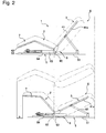
- Fig. 1 and Fig. 2 show a frame structure of a chair according to Embodiment 1 of the present invention.
- Reference numeral 1 indicates a whole chair, roughly comprising: a chair body 4 having a seat part 2 and a backrest part 3; and a pedestal supporting part 5 for supporting the chair body 4, and a reclining mechanism 6 is provided between the supporting part 5 and the chair body part 4, for shifting the seat part 2 and the backrest part 3 forward, simultaneously with backward reclining movement of the backrest part 3 in a state where an angle between the seat part 2 and the backrest part 3 is fixed.
- a footrest part 7 is provided in front of the seat part 2 of the chair body 4, and in one frame structure, the seat part 2, the backrest part 3 and the 7 are integrally formed.
- a pair of longitudinal frames 41, 41 and a pair of horizontal frames 42, 42 form the frame structure, in which the longitudinal frames 41 are bent inward at a prescribed angle on the boundary between the backrest part 3 and the seat part 2, and also bent outward at a prescribed angle on the boundary between the seat part 2 and the footrest part 7.
- the supporting part 5 also has a rectangular frame structure, and placed in a region vertically projecting the chair body 4 with the backrest part 3 in nearly a raised state.
- the reclining mechanism 6 is configured to comprise: link members 61, 61 for linking the supporting part 5 and the backrest part 3; a pair of rollers 62 as shifting parts provided in the vicinity of the sides of the bent part between the seat part 2 of the chair body 4 and the backrest part 3; a pair of U-shaped roller guides 63 as guide parts, with the rollers 62 rotatably and longitudinally shiftably attached thereto; and an actuator 64 for changing the attitude of the chair body 4.
- the link members 61, 61 are provided respectively on both sides, and one end of each of the link members 61, 61 is pivotally linked to the center of the frame part 41a on each side of the backrest part 3, while the other end is pivotally linked to each rear end corner of the supporting part 5.
- each of the rollers 62 is rotatably attached to the outer surface of an attached board 62a fixed to the lower end part of each of the frame parts 41a of the backrest part 3.
- a linking shaft 62b links the right and left rollers 62, 62.
- the right and left rollers 62, 62 and the linking shaft 62b constitute the shifting part.
- the mutually parallel roller guides 63 with a prescribed length are fixed to right and left frames 51, 51 of the supporting part 5 such that U-shaped grooves to install rollers 62 are turned inward.
- the actuator 64 is configured to extend and shrink linearly longitudinally, and the rear end thereof is pivotally linked to the linking shaft 62b between the rollers 62 while the front end thereof is pivotally linked to a front frame 52 of the supporting part 5.
- the configuration of the actuator 64 is not particularly limited so long as it has an extendable and shrinkable drive, and in this example, the actuator 64 is configured to extend and shrink by a motor 64a and a feed screw system which is formed by combination of a feed screw shaft and a nut (not shown), between a cylindrical body 64b and a rod 64c to be inserted in the cylindrical body 64b.
- the actuator 64 is shrunk. With this shrinkage, as shown in Fig. 2, the rollers 62 rotates and shifts forward along the roller guides 63 and the lower end of the backrest part 3 is then shifted forward while the backrest part 3 is pulled by the link members 61 and reclined at a prescribed angle. Since the lower end of the backrest part 3 is shifted forward while the backrest part 3 is reclined, the backward protrusion of the backrest part 3 can be prevented.
- the footrest part 7 and the seat part 2 are lifted upward by a length corresponding to the reclined length of the backrest part 3, and hence the forward protrusion is a length "b" shorter than in the case of reclining only the backrest part (cf. the chained lines in Fig. 2), which can make the footprint small.
- the figuration of the chair body 4 remains unchanged even when the backrest part 3 is reclined, the position of the body in contact with the backrest part 3 remains unchanged, and in the case of a massage chair having a massaging tool on the backrest part 3, since an adjusted position of the massaging tool remains unchanged, readjustment of the massaging position is not necessary when the angle of the backrest part 3 is changed.
- the angle between the seat part 2 and the footrest part 7 remains unchanged, feet supported by the footrest part are raised simultaneously with reclining of the backrest part 3, which can help cure swelling of the feet.
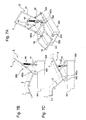
- Fig. 3 shows a chair according to Embodiment 2 of the present invention.
- a front supporting leg 251 and a rear supporting leg 252 are formed with a longitudinal space therebetween in the supporting part 205.
- the front supporting leg 251 and the rear supporting leg 252 are integrally linked to each other by a longitudinally frame 253 which is made of a U-shaped member, and extends longitudinally. Further, the upper parts of the front supporting leg 251 are linked by a horizontally extending front frame 254.
- a reclining mechanism 206 is configured to comprise: a front roller 262 as a front shifting part provided on the front supporting leg 251; a front roller guide 263 as a front guiding part provided along the seat part 2, with the front roller 262 longitudinally shiftably attached thereto; a rear roller 265 serving a rear shifting part provided on the rear supporting leg 252; a rear roller guide 266 as a rear guiding part provided along the backrest part 3, with the rear roller 265 longitudinally shiftably attached thereto; and an extendable and shrinkable actuator 64 member linking the front frame 254 of the supporting part 205 and a central frame 255 positioned on the boundary between the backrest part 3 and the seat part 2 of the chair body 4, and also configured to change the attitude of the chair body 4 by the extension or shrinkage of the actuator 64.
- the actuator 64 is disposed on the side of the under surface of the seat part 2, it may be disposed on the side of the backrest part 3 so as to link the rear supporting leg 252 of the supporting part 205 and the backrest part 3 of the chair body 4. Further, the actuator 64 may be configured to link the longitudinal frame 253 and the backrest part 3 of the chair body 4.
- the actuator 64 is shrunk as shown in Figs 3B and 3C.
- the front roller 262 and the back roller 265 rotate and shift backward along the front roller guide 263 and the rear roller guide 266 to shift the lower end of the backrest part 3 relatively forward, while the front end of the seat part 2 is lifted upward, thereby to recline the backrest part 3 at a prescribed angle. Therefore, with the backrest part 3 shifting forward while being reclined, the backward protrusion of the backrest part 3 can be prevented.
- the protruding length is shorter than in the case where those parts horizontally shift, which can make the footprint small. Further, since the figuration of the chair body 4 remains unchanged, the position of the body in contact with the backrest part 3 remains unchanged.
- the chair comprises no link member for supporting the backrest part 3, thereby to have a similar outside shape to that of a chair with its moving part made invisible.
- the seat part 2 constituting the chair body 4 the backrest part 3 and the footrest part 7 are not integrally formed by frames as in Embodiment 1, but a frame body constituting the seat part 2 and the footrest part 7 are integrally linked with the frame body constituting the backrest part 3, and meanwhile Embodiment 1 and Embodiment 2 are common in that the angles of those components are fixed.
- Fig. 4 shows a chair according to Embodiment 3 of the present invention.
- a pedestal supporting part 305 is provided with a pair of supporting walls 351, which are respectively positioned on both sides of the chair body 4, and support the chair body 4 at their front and back sides.
- a pair of fixed walls 21 are provided on the seat part 2 in a protruding condition so as to be opposed to the supporting walls 351, and the fixed walls 21 are supported by the supporting walls 351.
- the reclining mechanism 306 is characterized in comprising: a front sliding projection 362 and a rear sliding projection 365, which are disposed on each of the fixed walls 21 provided on the seat part 2 of the chair body 4; a front guide groove 363 and a rear guide groove 366, which are disposed on each side of the supporting walls 351, longitudinally movably support the front sliding projection 362 and the rear sliding projection 365, and serve as guides for guiding upward the front sliding projection 362, relatively rather than the rear sliding projection 365, to recline the attitude of the backrest part 3 backward, as the chair body 4 is slid forward; and the actuator 64 which is extendable and shrinkable, and links the chair body 4 and the supporting part 305 to change the attitude of the chair body 4.
- One end of the actuator 64 is pivotally linked to a bracket 352 positioned at the rear lower ends of the supporting walls 351 on the supporting part 305 while the other end of the actuator 64 is pivotally linked to the center of the shaft 22 running between the two front sliding projections 362 positioned at the front upper ends of the fixed walls 21 on the chair body 4.
- the actuator 64 is positioned on almost the same sloping line as the front guiding grooves 363.
- the protruding length is shorter than in the case where those parts horizontally shift, which can make the footprint small. Further, since the figuration of the chair body 4 remains unchanged, the position of the body in contact with the backrest part 3 remains unchanged.
- the actuator 64 and the like are made invisible by the supporting walls 351 and the fixed walls 21, thereby making it easier to protect the moving part.
- the chair body 4 may be supported from below and frame members for supporting the front sliding projection 362 and the rear sliding projection 365 on the each side thereof may be used.
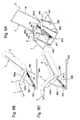
- Fig. 5 shows a chair according to Embodiment 4 of the present invention.
- the reclining mechanism 406 is configured to comprise: a link member 61 member linking a supporting part 405 in frame form and the backrest part 3; a wheel 462 as a shifting part provided in the vicinity of the boundary between the seat part 2 of the chair body 4 and the backrest part 3; and a motor 464 as an actuator for changing the attitude of the chair body 4.
- the wheel 462 that rotates in contact with the supporting part 405 is used as the shifting part, and the motor 464 for rotationally driving the wheel 462 is used as the actuator.
- the supporting part 405 is formed of a rectangular frame body as in Embodiment 1
- a width between right and left frames 451 is larger than the corresponding width in Embodiment 1
- the wheel 462 is rotatably in contact with the upper surface of each of the right and left frames 451.
- a rubber tire is used as the wheel 462, which is rotatably attached to an attached plate 462a fixed to the vicinity of the boundary between the seat part 2 of the chair body 4 and the backrest part 3, and shifts along the surface of the frame 451 by the force of friction with the frame 451.
- a motor shaft is disposed on the side of the supporting part 405, in parallel to the frame 451 so as not to extend out from the supporting part 405. Since the driving shaft of the motor 464 is orthogonal to the wheel shaft of the wheel 462, a direction of power transmission is changed by a power transmitting mechanism composed of a worm and a worm wheel (not shown).
- limit switches 467 and 468 are provided for detecting the positions of the backrest part 3 at the minimum reclining angle (raised position), so as to limit a prescribed range of the reclining angle of the backrest part 3, and at the maximum reclining angle (most reclined position).
- the limit switches 467 and 468 are disposed sandwiching the linking parts of the link members 61 on the frame 41a of the backrest part 3, and turned on and off depending on the slope of the link members 61.
- the backrest part 3 shifting forward while being reclined, the backward protrusion of the backrest part 3 can be prevented. Further, with the seat part 2 and the footrest part 7 shifting obliquely upward while changing the angle therebetween, the forward protrusion is shorter than in the case of horizontal shifting, which can make the footprint small. Moreover, since the figuration of the chair body 4 remains unchanged, the position of the body in contact with the backrest part 3 remains unchanged.
- Fig. 6 shows a transformed example of Embodiment 4.
- the reclining mechanism 406 is added with a pinion 469a disposed in the vicinity of the boundary between the seat part 2 and the backrest part 3, and a rack 469b which is disposed on the supporting part 405 and engaged with the pinion 469a.
- the pinion 469a is pivotally disposed along with the wheel 462, and rotationally driven by the motor 464, integrally with the wheel 462. Only the wheel 462 may be driven while the pinion 469a may not, or only the pinion 469a may be driven while the wheel 462 may not. Further, the wheel 462 may not be disposed and the pinion 469a may support the chair body 4.
- Fig. 7 shows a chair according to Embodiment 5.
- the supporting part and the actuator are configured differently from those in Embodiment 4, and other components are configured in the same manner as in Embodiment 4.
- a supporting part 505 is not formed by a frame body, but by a block body comprising right and left guide walls 551 and a bottom wall 552 for liking the lower ends of the right and left guide walls 551, where the upper surfaces of the guide walls 551 are formed high.
- the reclining mechanism 506 comprises: the link member 61 member linking the supporting part 505 and the backrest part 3; and the wheel 462 as a shifting part provided in the vicinity of the boundary between the seat part 2 of the chair body 4 and the backrest part 3, where the wheel 462 at the lower end of the backrest part 3 rotates and shifts along the upper surface of each of the guide walls 551.
- the actuator 64 is not configured to be rotary, but to extend and shrink as in Embodiment 1, and is disposed between the supporting part 505 and the backrest part 3.
- the upper end of the actuator 64 is linked to the intermediate frame 44 provided in the middle of the height of the backrest part 3.
- the intermediate frame 44 runs between the right and left frames 41, 41 of the backrest part 3.
- the lower end of the actuator 64 is rotatably linked to the bottom wall 552 of the supporting part 505.
- the actuator 64 when the backrest part is to be reclined, the actuator 64 is shrunk as shown in Figs 7B and 7C. As the actuator 64 is shrunk, the wheel 462 rotates and shifts forward along each of the right and left guide walls 551, and the lower end of the backrest part 3 shifts forward while the backrest part 3 is pulled by the link member 61 and reclined at a prescribed angle. Therefore, since the backrest part 3 is shifted forward while reclined, the backward protrusion of the backrest part 3 can be prevented.
- the seat part 2 of the chair body 4 and the footrest part 7 and the angle between the seat part 2 and the backrest part 3 are fixed, the seat part 2 and the footrest part 7 are lifted upward by a length corresponding to the reclined length of the backrest part 3. Moreover, since the figuration of the chair body 4 remains unchanged even with the backrest part 3 reclined, the position of the body in contact with the backrest part 3 remains unchanged.
- Fig. 8 shows a transformed example of Embodiment 5.
- the actuator 64 is provided between the supporting part 505 and the seat part 2.
- the upper end of the actuator 64 is linked to the intermediate frame 45 provided at the front end of the seat part 2.
- the lower end of the actuator 64 is rotatably linked to the bottom wall 552 of the supporting part 505.
- the actuator 64 When the backrest part 3 is to be reclined, the actuator 64 is extended as shown in Figs 8B and 8C. As the actuator 64 is extended, the front end of the seat part 2 is lifted and the lower end of the backrest part 3 shifts forward while the backrest part 3 is pulled by the link members 61 and reclined at a prescribed angle.
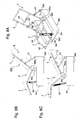
- Fig. 9 shows a chair according to Embodiment 6.
- Embodiment 6 is the same as Embodiment 1 in terms of the chair body, but essentially different in the configuration of the reclining mechanism.
- the reclining mechanism 606 is configured to comprise: a four-node link system 661 member linking the seat part 2 of the chair body 4 and the supporting part 605; and an extendable and shrinkable actuator 64 provided diagonally to the four-node link 661.
- the four-node link 661 comprises a pair of (right and left) front link members 662 and a pair of (right and left) rear link members 663, where the front link member 662 is provided between the front end of the supporting part 605 and the position slightly forward from the center of the seat part 2 of the chair body 4, and the rear link member 663 is provided between the middle of the supporting part 605 and the vicinity of the boundary between the seat part 2 and the backrest part 3.
- the upper ends of the front link member 662 and the rear link member 663 are rotatably linked to a fixed board 662a fixed to each of the right and left frames 41b and 41b, while the lower ends of the front link member 662 and the rear link member 663 are rotatably linked to the supporting part 605 via brackets.
- the front link member 662 is longer than the rear link member 663, and as shown in Fig. 9B, when the backrest part 3 is in a raised position, both the front link member 662 and the rear link member 663 are inclined with the upper end thereof more backward than the lower end thereof, and the rear link member 663 has a smaller backward inclination angle than that of the front link member 662.
- the rear link member 663 rotates with a larger angle; when the backrest part 3 is in a most reclined position, the upper end of the front link member 662 has not reached the highest position and is inclined backward while the upper end of the rear link member 663 has passed over the highest position and is inclined upward, which shifts the lower end of the backrest part 3 forward, simultaneously with backward reclining movement of the backrest part 3, and also lifts the front end of the seat part 2 upward.
- the actuator 64 is the same extendable and shrinkable actuator as that in Embodiment 1, being positioned obliquely between the lower end of the front link member 662 and the upper end of the rear link member 663 in the side views of Figs. 9B and 9C, and the front end of the actuator 64 is rotatably linked to the bracket 651 fixed to the supporting part 605 while the rear end of the actuator 64 is rotatably liked to the center of the intermediate frame 43 disposed in the vicinity of the boundary between the seat part 2 of the chair body 4 and the backrest part 3.
- Fig. 9B shows the attitude of the chair with the backrest part in a raised position.
- the actuator 64 is in a most extended state, and is shrunk when the backrest part 3 is to be reclined.
- the front link member 662 and the rear link member 663 are both rotated counterclockwise, and since the upper end of the front link member 662 shifts upward in a greater degree than the upper end of the rear link member 663, and the rear link member 663 shifts forward in a greater degree than the front link member 662, the backrest part 3 is reclined while the lower end thereof is shifted forward, and the front end of the seat part 2 is lifted upward, which can prevent the backward protrusion of the backrest part 3 and also make the footprint small.
- the chair of the present invention is suitable for a massage chair having a massaging tool on a backrest part, it is not limited to a massage chair, and is usable for a variety of reclining chairs. Further, while the chair of the present invention is described by taking the chairs having a footrest part as examples in the above embodiments, the reclining system of the present invention is applicable to a chair having no footrest.
Landscapes
- Health & Medical Sciences (AREA)
- Dentistry (AREA)
- General Health & Medical Sciences (AREA)
- Chairs For Special Purposes, Such As Reclining Chairs (AREA)
- Chairs Characterized By Structure (AREA)
Applications Claiming Priority (2)
| Application Number | Priority Date | Filing Date | Title |
|---|---|---|---|
| JP2004010997 | 2004-01-19 | ||
| JP2004010997A JP2005198979A (ja) | 2004-01-19 | 2004-01-19 | 椅子 |
Publications (2)
| Publication Number | Publication Date |
|---|---|
| EP1555005A2 true EP1555005A2 (de) | 2005-07-20 |
| EP1555005A3 EP1555005A3 (de) | 2005-08-31 |
Family
ID=34616949
Family Applications (1)
| Application Number | Title | Priority Date | Filing Date |
|---|---|---|---|
| EP04030739A Withdrawn EP1555005A3 (de) | 2004-01-19 | 2004-12-23 | Neigungsverstellbarer Stuhl |
Country Status (5)
| Country | Link |
|---|---|
| EP (1) | EP1555005A3 (de) |
| JP (1) | JP2005198979A (de) |
| KR (1) | KR20050076623A (de) |
| CN (1) | CN1647724A (de) |
| TW (1) | TW200531656A (de) |
Cited By (8)
| Publication number | Priority date | Publication date | Assignee | Title |
|---|---|---|---|---|
| US7722114B2 (en) | 2008-04-11 | 2010-05-25 | Jobri Llc | Zero gravity wall hugger recliner |
| WO2012087743A3 (en) * | 2010-12-20 | 2012-10-26 | Restoration Robotics, Inc. | Adjustable hair transplantation chair |
| KR101332926B1 (ko) * | 2013-01-03 | 2013-11-26 | 매직라이프코리아(주) | 슬라이드식 안마의자 |
| KR101496306B1 (ko) * | 2013-05-21 | 2015-03-02 | 강원대학교산학협력단 | 수압식 안마기의 등받이 각도 조절장치 |
| EP2939646A4 (de) * | 2012-12-25 | 2016-08-10 | Jimho Robot Shanghai Co Ltd | Trainingsroboter zur rehabilitation der unteren gliedmassen |
| US10098470B2 (en) | 2013-06-19 | 2018-10-16 | Leggett & Platt, Inc. | Sofa having adjustable backrest position |
| CN113558923A (zh) * | 2021-06-04 | 2021-10-29 | 奥佳华智能健康科技集团股份有限公司 | 一种按摩椅 |
| WO2024207968A1 (zh) * | 2023-04-07 | 2024-10-10 | 锐迈科技股份有限公司 | 可活动的座椅单元和可活动座椅 |
Families Citing this family (21)
| Publication number | Priority date | Publication date | Assignee | Title |
|---|---|---|---|---|
| KR100893161B1 (ko) * | 2007-06-29 | 2009-04-17 | (주)대경산업 | 안마 의자 |
| KR100904886B1 (ko) * | 2008-06-27 | 2009-06-29 | (주)대경산업 | 안마 의자 및 안마 의자의 구동 방법 |
| JP5396978B2 (ja) | 2009-04-10 | 2014-01-22 | トヨタ紡織株式会社 | 車両用シート |
| CN101884470B (zh) * | 2009-05-11 | 2013-08-28 | 严能进 | 一种可坐可躺的座椅系统 |
| CN101889780B (zh) * | 2009-05-18 | 2013-08-28 | 严能进 | 一种坐躺两用的座椅系统 |
| JP2012070785A (ja) * | 2010-09-27 | 2012-04-12 | Panasonic Corp | リクライニング椅子およびこれを備える椅子式マッサージ機 |
| JP5364218B2 (ja) * | 2011-01-28 | 2013-12-11 | シャンハイ シンコール ファーニチャー プロダクツ カンパニー リミテッド | 角度調整型マッサージ装置 |
| SG2014005904A (en) | 2011-02-18 | 2014-03-28 | Daito Electric Machine Ind | Chair-type massage apparatus |
| TWM426338U (en) * | 2011-10-03 | 2012-04-11 | Johnson Health Tech Co Ltd | Flat reclining chair |
| KR101333318B1 (ko) * | 2012-02-22 | 2013-11-27 | 주식회사 이디 | 전동식 구동시스템을 구비한 보조의자 |
| CN103054687A (zh) * | 2012-08-15 | 2013-04-24 | 山东康泰实业有限公司 | 一种按摩椅靠背前滑装置 |
| CN103120613A (zh) * | 2013-01-31 | 2013-05-29 | 宁波康福特健身器械有限公司 | 一种改进型按摩椅 |
| JP6040817B2 (ja) | 2013-03-21 | 2016-12-07 | トヨタ紡織株式会社 | 乗物用シート |
| JP6305153B2 (ja) * | 2014-03-27 | 2018-04-04 | 株式会社きさく工房 | リクライニング機構並びに椅子、座椅子及び車椅子 |
| CN105078696A (zh) * | 2014-04-16 | 2015-11-25 | 宁波秉航电子科技有限公司 | 一种具有曲形导轨的按摩椅 |
| JP6191877B2 (ja) * | 2014-07-01 | 2017-09-06 | パナソニックIpマネジメント株式会社 | リクライニング椅子、および、これを備えるマッサージ機 |
| US9277822B1 (en) * | 2014-09-02 | 2016-03-08 | La-Z-Boy Incorporated | Furniture member with powered mechanism providing lift and zero gravity positions |
| TW201722318A (zh) * | 2015-12-30 | 2017-07-01 | Hern Juei Co Ltd | 快速組合椅具 |
| CN108937308A (zh) * | 2018-07-10 | 2018-12-07 | 深圳市晓控通信科技有限公司 | 一种具有清洁功能的智能沙发 |
| KR102802395B1 (ko) * | 2020-08-21 | 2025-05-07 | 주식회사 시디즈 | 의자 |
| KR20240004776A (ko) | 2021-05-31 | 2024-01-11 | 레마크로 머시너리 앤드 테크놀로지(우지앙) 컴퍼니 리미티드 | 등받이 간격 제로를 위한 연동 장치, 브라켓, 좌석 유닛 및 좌석 |
Family Cites Families (10)
| Publication number | Priority date | Publication date | Assignee | Title |
|---|---|---|---|---|
| US1438667A (en) * | 1922-08-26 | 1922-12-12 | Schops Hermann | Rocking chair |
| US2480552A (en) * | 1945-04-02 | 1949-08-30 | Vietor J Colvez | Chair |
| US3175860A (en) * | 1964-01-08 | 1965-03-30 | Tcherniavsky Victor | Convertible chair |
| US4214790A (en) * | 1979-01-25 | 1980-07-29 | Sieber Walter P | Orthopedic reclining chair |
| US4615336A (en) * | 1983-11-30 | 1986-10-07 | Fuji Medical Instruments Mfg. Co., Ltd. | Automatic massaging machine |
| NL8601457A (nl) * | 1986-06-05 | 1988-01-04 | Huka Bv Developments | Rolstoel met kantelbaar zitgedeelte. |
| US5249838A (en) * | 1990-09-21 | 1993-10-05 | Kulpa Judith I | Seating device having curved bottom tilting on roller and secured by reeved cable |
| AT402142B (de) * | 1993-03-15 | 1997-02-25 | Hoppe Kg Hodry Metallfab | Ruhesessel |
| US20020101102A1 (en) * | 2001-01-30 | 2002-08-01 | Chang Horng Jiun | Chair having forward tilting device |
| DE10114403A1 (de) * | 2001-03-23 | 2002-09-26 | Peter Hirsch | Sitz- und Liegestuhl |
-
2004
- 2004-01-19 JP JP2004010997A patent/JP2005198979A/ja not_active Withdrawn
- 2004-12-23 EP EP04030739A patent/EP1555005A3/de not_active Withdrawn
-
2005
- 2005-01-12 TW TW094100796A patent/TW200531656A/zh unknown
- 2005-01-12 CN CNA200510003832XA patent/CN1647724A/zh active Pending
- 2005-01-14 KR KR1020050003712A patent/KR20050076623A/ko not_active Ceased
Cited By (10)
| Publication number | Priority date | Publication date | Assignee | Title |
|---|---|---|---|---|
| US7722114B2 (en) | 2008-04-11 | 2010-05-25 | Jobri Llc | Zero gravity wall hugger recliner |
| WO2012087743A3 (en) * | 2010-12-20 | 2012-10-26 | Restoration Robotics, Inc. | Adjustable hair transplantation chair |
| US9962307B2 (en) | 2010-12-20 | 2018-05-08 | Restoration Robotics, Inc. | Adjustable hair transplantation chair |
| EP2939646A4 (de) * | 2012-12-25 | 2016-08-10 | Jimho Robot Shanghai Co Ltd | Trainingsroboter zur rehabilitation der unteren gliedmassen |
| US10010472B2 (en) | 2012-12-25 | 2018-07-03 | Jimho Robot (Shanghai) Co., Ltd. | Lower limbs rehabilitation training robot |
| KR101332926B1 (ko) * | 2013-01-03 | 2013-11-26 | 매직라이프코리아(주) | 슬라이드식 안마의자 |
| KR101496306B1 (ko) * | 2013-05-21 | 2015-03-02 | 강원대학교산학협력단 | 수압식 안마기의 등받이 각도 조절장치 |
| US10098470B2 (en) | 2013-06-19 | 2018-10-16 | Leggett & Platt, Inc. | Sofa having adjustable backrest position |
| CN113558923A (zh) * | 2021-06-04 | 2021-10-29 | 奥佳华智能健康科技集团股份有限公司 | 一种按摩椅 |
| WO2024207968A1 (zh) * | 2023-04-07 | 2024-10-10 | 锐迈科技股份有限公司 | 可活动的座椅单元和可活动座椅 |
Also Published As
| Publication number | Publication date |
|---|---|
| JP2005198979A (ja) | 2005-07-28 |
| KR20050076623A (ko) | 2005-07-26 |
| CN1647724A (zh) | 2005-08-03 |
| EP1555005A3 (de) | 2005-08-31 |
| TW200531656A (en) | 2005-10-01 |
Similar Documents
| Publication | Publication Date | Title |
|---|---|---|
| EP1555005A2 (de) | Neigungsverstellbarer Stuhl | |
| JP6144712B2 (ja) | 調整可能な家具 | |
| US11813213B2 (en) | Patient support apparatus | |
| EP3311700A1 (de) | Mechanischer erweiterungsmechanismus und sitzeinheit damit | |
| KR101891685B1 (ko) | 침대 가변형 휠체어 | |
| KR100960094B1 (ko) | 승강구동모듈이 힌지 결합된 승강의자 | |
| US20040227331A1 (en) | Multi-functional wheelchair | |
| US20180000253A1 (en) | Motorized mechanism and motorized furniture | |
| KR101799971B1 (ko) | 신체부위별 배치각도 조절형 전동 침대프레임 | |
| KR101629290B1 (ko) | 샴푸 전동 의자 | |
| US12520941B1 (en) | Seat bracket and zero-wall-gap seat with seat bracket | |
| JP5807311B2 (ja) | 起立補助機能をもった椅子座面、及び、それを用いた椅子 | |
| EP1032290B1 (de) | Lehnstuhl mit einer motorisch angetriebenen fussstütze,rückenlehne und sitzuntergestell | |
| EP3641594B1 (de) | Motorisierter schwerkraftloser stuhl | |
| KR101406144B1 (ko) | 효도의자 | |
| JP3072908B2 (ja) | リクライニングチェア | |
| KR20230082892A (ko) | 전동 휠체어 시트 리프트 매커니즘 | |
| TWI577315B (zh) | Electric chair | |
| KR101485492B1 (ko) | 의자 캐스터 | |
| KR20220031813A (ko) | 스탠딩 기능을 포함한 휠체어 | |
| JP3729714B2 (ja) | 椅子 | |
| JPH0542772Y2 (de) | ||
| CN222982732U (zh) | 电动座椅机械伸展装置 | |
| US20260123751A1 (en) | Seat bracket and zero-wall-gap seat with seat bracket | |
| JP2004141506A (ja) | 昇降自在椅子 |
Legal Events
| Date | Code | Title | Description |
|---|---|---|---|
| PUAI | Public reference made under article 153(3) epc to a published international application that has entered the european phase |
Free format text: ORIGINAL CODE: 0009012 |
|
| PUAL | Search report despatched |
Free format text: ORIGINAL CODE: 0009013 |
|
| AK | Designated contracting states |
Kind code of ref document: A2 Designated state(s): AT BE BG CH CY CZ DE DK EE ES FI FR GB GR HU IE IS IT LI LT LU MC NL PL PT RO SE SI SK TR |
|
| AX | Request for extension of the european patent |
Extension state: AL BA HR LV MK YU |
|
| AK | Designated contracting states |
Kind code of ref document: A3 Designated state(s): AT BE BG CH CY CZ DE DK EE ES FI FR GB GR HU IE IS IT LI LT LU MC NL PL PT RO SE SI SK TR |
|
| AX | Request for extension of the european patent |
Extension state: AL BA HR LV MK YU |
|
| AKX | Designation fees paid | ||
| STAA | Information on the status of an ep patent application or granted ep patent |
Free format text: STATUS: THE APPLICATION IS DEEMED TO BE WITHDRAWN |
|
| 18D | Application deemed to be withdrawn |
Effective date: 20060301 |
|
| REG | Reference to a national code |
Ref country code: DE Ref legal event code: 8566 |