EP1554831B1 - Frequenzsprung-ofdma-verfahren mittels verwendung von kammmuster-symbolen - Google Patents
Frequenzsprung-ofdma-verfahren mittels verwendung von kammmuster-symbolen Download PDFInfo
- Publication number
- EP1554831B1 EP1554831B1 EP02788992.2A EP02788992A EP1554831B1 EP 1554831 B1 EP1554831 B1 EP 1554831B1 EP 02788992 A EP02788992 A EP 02788992A EP 1554831 B1 EP1554831 B1 EP 1554831B1
- Authority
- EP
- European Patent Office
- Prior art keywords
- sub
- comb
- symbols
- carriers
- frequency
- Prior art date
- Legal status (The legal status is an assumption and is not a legal conclusion. Google has not performed a legal analysis and makes no representation as to the accuracy of the status listed.)
- Expired - Fee Related
Links
Images


Classifications
-
- H—ELECTRICITY
- H04—ELECTRIC COMMUNICATION TECHNIQUE
- H04L—TRANSMISSION OF DIGITAL INFORMATION, e.g. TELEGRAPHIC COMMUNICATION
- H04L27/00—Modulated-carrier systems
- H04L27/26—Systems using multi-frequency codes
- H04L27/2601—Multicarrier modulation systems
- H04L27/2626—Arrangements specific to the transmitter only
- H04L27/2627—Modulators
- H04L27/2628—Inverse Fourier transform modulators, e.g. inverse fast Fourier transform [IFFT] or inverse discrete Fourier transform [IDFT] modulators
-
- H—ELECTRICITY
- H04—ELECTRIC COMMUNICATION TECHNIQUE
- H04B—TRANSMISSION
- H04B1/00—Details of transmission systems, not covered by a single one of groups H04B3/00 - H04B13/00; Details of transmission systems not characterised by the medium used for transmission
- H04B1/69—Spread spectrum techniques
- H04B1/713—Spread spectrum techniques using frequency hopping
- H04B1/7136—Arrangements for generation of hop frequencies, e.g. using a bank of frequency sources, using continuous tuning or using a transform
-
- H—ELECTRICITY
- H04—ELECTRIC COMMUNICATION TECHNIQUE
- H04B—TRANSMISSION
- H04B1/00—Details of transmission systems, not covered by a single one of groups H04B3/00 - H04B13/00; Details of transmission systems not characterised by the medium used for transmission
- H04B1/69—Spread spectrum techniques
- H04B1/713—Spread spectrum techniques using frequency hopping
- H04B1/7143—Arrangements for generation of hop patterns
-
- H—ELECTRICITY
- H04—ELECTRIC COMMUNICATION TECHNIQUE
- H04L—TRANSMISSION OF DIGITAL INFORMATION, e.g. TELEGRAPHIC COMMUNICATION
- H04L27/00—Modulated-carrier systems
- H04L27/26—Systems using multi-frequency codes
- H04L27/2601—Multicarrier modulation systems
- H04L27/2602—Signal structure
- H04L27/261—Details of reference signals
- H04L27/2613—Structure of the reference signals
-
- H—ELECTRICITY
- H04—ELECTRIC COMMUNICATION TECHNIQUE
- H04L—TRANSMISSION OF DIGITAL INFORMATION, e.g. TELEGRAPHIC COMMUNICATION
- H04L27/00—Modulated-carrier systems
- H04L27/26—Systems using multi-frequency codes
- H04L27/2601—Multicarrier modulation systems
- H04L27/2626—Arrangements specific to the transmitter only
- H04L27/2627—Modulators
- H04L27/2634—Inverse fast Fourier transform [IFFT] or inverse discrete Fourier transform [IDFT] modulators in combination with other circuits for modulation
-
- H—ELECTRICITY
- H04—ELECTRIC COMMUNICATION TECHNIQUE
- H04L—TRANSMISSION OF DIGITAL INFORMATION, e.g. TELEGRAPHIC COMMUNICATION
- H04L27/00—Modulated-carrier systems
- H04L27/26—Systems using multi-frequency codes
- H04L27/2601—Multicarrier modulation systems
- H04L27/2647—Arrangements specific to the receiver only
- H04L27/2655—Synchronisation arrangements
- H04L27/2657—Carrier synchronisation
-
- H—ELECTRICITY
- H04—ELECTRIC COMMUNICATION TECHNIQUE
- H04L—TRANSMISSION OF DIGITAL INFORMATION, e.g. TELEGRAPHIC COMMUNICATION
- H04L5/00—Arrangements affording multiple use of the transmission path
- H04L5/0001—Arrangements for dividing the transmission path
- H04L5/0003—Two-dimensional division
- H04L5/0005—Time-frequency
- H04L5/0007—Time-frequency the frequencies being orthogonal, e.g. OFDM(A), DMT
-
- H—ELECTRICITY
- H04—ELECTRIC COMMUNICATION TECHNIQUE
- H04L—TRANSMISSION OF DIGITAL INFORMATION, e.g. TELEGRAPHIC COMMUNICATION
- H04L5/00—Arrangements affording multiple use of the transmission path
- H04L5/003—Arrangements for allocating sub-channels of the transmission path
- H04L5/0044—Arrangements for allocating sub-channels of the transmission path allocation of payload
-
- H—ELECTRICITY
- H04—ELECTRIC COMMUNICATION TECHNIQUE
- H04B—TRANSMISSION
- H04B1/00—Details of transmission systems, not covered by a single one of groups H04B3/00 - H04B13/00; Details of transmission systems not characterised by the medium used for transmission
- H04B1/69—Spread spectrum techniques
- H04B1/713—Spread spectrum techniques using frequency hopping
- H04B1/7136—Arrangements for generation of hop frequencies, e.g. using a bank of frequency sources, using continuous tuning or using a transform
- H04B2001/71367—Arrangements for generation of hop frequencies, e.g. using a bank of frequency sources, using continuous tuning or using a transform using a transform
-
- H—ELECTRICITY
- H04—ELECTRIC COMMUNICATION TECHNIQUE
- H04B—TRANSMISSION
- H04B1/00—Details of transmission systems, not covered by a single one of groups H04B3/00 - H04B13/00; Details of transmission systems not characterised by the medium used for transmission
- H04B1/69—Spread spectrum techniques
- H04B1/713—Spread spectrum techniques using frequency hopping
- H04B1/715—Interference-related aspects
- H04B2001/7154—Interference-related aspects with means for preventing interference
-
- H—ELECTRICITY
- H04—ELECTRIC COMMUNICATION TECHNIQUE
- H04L—TRANSMISSION OF DIGITAL INFORMATION, e.g. TELEGRAPHIC COMMUNICATION
- H04L1/00—Arrangements for detecting or preventing errors in the information received
- H04L1/0001—Systems modifying transmission characteristics according to link quality, e.g. power backoff
- H04L1/0023—Systems modifying transmission characteristics according to link quality, e.g. power backoff characterised by the signalling
- H04L1/0025—Transmission of mode-switching indication
-
- H—ELECTRICITY
- H04—ELECTRIC COMMUNICATION TECHNIQUE
- H04L—TRANSMISSION OF DIGITAL INFORMATION, e.g. TELEGRAPHIC COMMUNICATION
- H04L25/00—Baseband systems
- H04L25/02—Details ; arrangements for supplying electrical power along data transmission lines
- H04L25/0202—Channel estimation
- H04L25/0224—Channel estimation using sounding signals
- H04L25/0226—Channel estimation using sounding signals sounding signals per se
-
- H—ELECTRICITY
- H04—ELECTRIC COMMUNICATION TECHNIQUE
- H04L—TRANSMISSION OF DIGITAL INFORMATION, e.g. TELEGRAPHIC COMMUNICATION
- H04L5/00—Arrangements affording multiple use of the transmission path
- H04L5/003—Arrangements for allocating sub-channels of the transmission path
- H04L5/0048—Allocation of pilot signals, i.e. of signals known to the receiver
Definitions
- the present invention relates to an Orthogonal Frequency Division Multiple Access (OFDMA) method; and, more particularly, to a frequency hopping OFDMA method of comb symbols in a wireless mobile communication system.
- OFDMA Orthogonal Frequency Division Multiple Access
- An Orthogonal Frequency Division Multiplexing (OFDM) method is a multi-carrier transmission method which divides an entire usable frequency band into a predetermined number of narrow bands, modulates the sub-carriers of the narrow bands in parallel, and transmits the modulated sub-carriers. To each sub-carrier, low-rate data, which has a small amount of data, are allocated.
- the applied modulation methods are diverse from simple Quadrature Phase Shift Keying (QPSK) to 256-Quadrature Amplitude Modulation (QAM) according to the change of data capacity or definite transmission requests.
- Channel signals have orthogonality to approach another channels without causing interference. Since no other sub-carrier can affect the center frequency of each channel, the frequency utility efficiency is high. Since each sub-carrier is processed into narrow band signals, such as 1 Khz, the transmission rate is low. So, although time delay is caused, such as 500 nanoseconds, while the channel signals are multi-reflected and transmitted, the interference between the OFDM symbols can be removed.
- the sub-carriers used in the OFDM method have orthogonality, the frequency utility efficiency is increased and multi-path channel problem can be overcome only with a simple frequency domain equalizer having one tab. Since the OFDM method can be implemented at a high speed using Fast Fourier Transform (FFT), the OFDM method is used as a transmission method for high-speed digital communication systems recently.
- FFT Fast Fourier Transform
- the OFDM method is used in wireless communication systems, such as Digital Audio Broadcasting (DAB), Digital Video Broadcasting (DVB), Institute of Electrical and Electronics Engineers (IEEE) 802.11a, and High Performance Radio Local Area Network 2 (HIPERLAN/2).
- DMB Digital Audio Broadcasting
- DVD Digital Video Broadcasting
- IEEE Institute of Electrical and Electronics Engineers 802.11a
- HIPERLAN/2 High Performance Radio Local Area Network 2
- Discrete MultiTone which is similar to the OFDM, is used in wired communication systems, such as x Digital Subscriber Line (xDSL).
- xDSL Digital Subscriber Line
- TDMA OFDM-Time Division Multiple Access
- FDMA OFDM-Frequency Division Multiple Access
- CDMA OFDM-Code Division Multiple Access
- each mobile station can use predetermined sub-carriers among the entire sub-carriers all the time.
- the sub-carriers can be allocated variably according to the requests from the mobile stations.
- resources can be distributed efficiently by allocating sub-carriers differently according to a data transmission rate requested by each mobile station.
- the OFDMA provides a high transmission efficiency, because it does not require any preamble that is requested in an OFDM-TDMA system.
- the OFDMA method is suitable when a large number of sub-carriers are in use, that is, when the amplitude of an FFT unit is large. So, it can be applied efficiently to a wireless communication system having a cell of wide area that is a cell whose delay spread is relatively large.
- frequency hopping OFDMA (FH-OFDMA) is used to increase frequency diversity effect and obtain interference average effect by overcoming sub-carriers in deep fading or the sub-carrier interference by another mobile station. More details on this are described in a book by Richard van Nee and Ramjee Prasad, entitled “OFDM Wireless Multimedia Communications,” Artech House, 2000 .
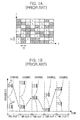
- Fig. 1A is a diagram showing a frequency 'hopping pattern of a cluster in accordance with a conventional OFDMA method.
- different frequency bands a, b and c are allocated according to a data transmission rate requested by a mobile station.
- the allocated frequency band is changed by performing frequency hopping based on time.
- the vertical axis 11 of each rectangular cell of Fig. 1A is a set of consecutive sub-carriers in the frequency domain, that is, a frequency band which is the number of sub-carriers within a rectangular cell * sub-carrier frequency interval (cluster), and the horizontal axis 10 of each rectangular cell indicates a symbol period.
- a predetermined number of neighboring sub-carriers are grouped among the entire sub-carriers to form a cluster and allocated to mobile stations on a cluster basis.
- the cluster performs frequency hopping based on a time slot so that the cluster could not fall into frequency null continuously.
- Fig. 1B is a diagram showing clusters falling into frequency null during frequency hopping in the conventional OFDMA method.
- the clusters 40 and 41 perform frequency hopping randomly based on a time slot.
- Each cluster is a set of consecutive sub-carriers.
- burst errors occur.
- interleaving or encoding is performed.
- the conventional method using clusters has a problem that the mobile station consumes a great deal of power because it performs FFT with respect to the entire sub-carriers, even if it has a cluster assigned to itself. Also, the conventional method cannot overcome the burst errors in case that the data of a packet are not long enough to perform interleaving, such as a control signal.
- an object of the present invention to provide a frequency hopping Orthogonal Frequency Division Multiple Access (OFDMA) method using symbols of a comb pattern, i.e., comb symbols, the method that can overcome burst errors even when a short packet is transmitted by allocating comb symbols to mobile stations, instead of allocating clusters, as sub-carriers of the OFDMA.
- OFDMA Orthogonal Frequency Division Multiple Access
- the method can reduce the amount of Fast Fourier Transform (FFT) computation by allocating the comb symbols to mobile stations as sub-carriers of the OFDMA.
- FFT Fast Fourier Transform
- the method can reduce the amount of FFT computation by allocating the comb symbols to mobile stations as sub-carriers of the OFDMA, when the comb symbols are allocated to the mobile stations additionally.
- Each comb symbol includes sub-carriers adjacent to the sub-carriers of the comb symbols that are already allocated to a mobile station and has the same size as the already allocated symbols.
- the method can reduce the amount of FFT computation by setting up the minimum frequency hopping unit of the comb symbols as the size of the comb symbols.
- the method can reduce the amount of FFT computation and increase frequency diversity by setting up a minimum frequency hopping unit as the size of the first allocated comb symbol to thereby change the interval of sub-carriers according to the frequency hopping, when the comb symbols are allocated additionally.
- the method can reduce the amount of FFT computation and improve a frequency utility efficiency by grouping sub-carriers according to the size of a comb symbol, allocating the comb symbols a predetermined number of sub-carrier groups that are suitable for a data transmission rate, and performing frequency hopping.
- the method can prevent interference between cells by making all mobile stations of a cell of a base station have the same frequency hopping pattern.
- the method can minimize the interference between cells by differentiating the frequency hopping patterns of comb symbols that are allocated to mobile stations according to the cell of each base station.
- the method wherein mobile stations can obtain channel information on the entire band with a least amount of power by allocating comb symbols which are formed of a group of sub-carriers having a least amount of FFT computation to a pilot tone and not performing frequency hopping.
- the method can allocate comb symbols to be orthogonal to each other in a cell by constructing a structure of a tree or a structure of multiple trees with comb-patterned symbols of various sizes according to the data transmission rate and allocating the comb symbols to mobile stations according to the tree structure or the multiple tree structure in a cell of a base station.
- a method for performing frequency hopping Orthogonal Frequency Division Multiple Accesses includes the steps of: a) allocating frequency domain signals X(k) of a comb pattern to a modulated data sequence, X(k) being comb symbols and k being a frequency index; b) performing frequency hopping so that the comb symbols could have an independent frequency offset; and c) performing inverse Fast Fourier Transform (FFT) on the comb symbols to be transformed to time domain signals x(n) and transmitting the time domain signals x(n), n being a time index.
- OFDMA Orthogonal Frequency Division Multiple Accesses
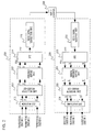
- Fig. 2 is a block diagram illustrating a frequency hopping Orthogonal Frequency Division Multiple Access (FH-OFDMA) system using symbols of a comb pattern, i.e., comb symbols, in accordance with the present invention.
- the FH-OFDMA communication system is formed of a transmitting system 210 and receiving system 230.
- the transmitting system 210 includes a modulation unit 211, a sub-carrier allocation unit 212, a frequency hopping unit 213, an Inverse Fast Fourier Transform (IFFT) 214, and a radio signal transmitting unit 215.
- IFFT Inverse Fast Fourier Transform
- Transmitting data sequences are modulated in the modulation unit 211 in a widely known modulation method, such as Quadrature Phase Shift Keying (QPSK) and mapped to complex numbers.
- QPSK Quadrature Phase Shift Keying
- the modulation method is an option of a system designer and it is not limited to a particular modulation method in the present invention.
- Comb symbols each including a different number of sub-carriers, are allocated to a plurality of mobile stations by the sub-carrier allocation unit 212 according to each requested transmission rate. Then, complex numbers modulated in the modulation unit 211 are allocated to each sub-carrier signal.
- the frequency hopping unit 213 performs frequency hopping of the sub-carriers according to a time slot in a given pattern to thereby output frequency domain signals X(k) to the IFFT 214.
- the frequency domain signals X(k) are converted to time-domain signals x(n) in the IFFT 214.
- guard intervals are added to the time-domain signals x(n) to prevent inter-symbol interference caused by multi-path fading in the radio signal transmitting unit 215.
- the receiving system 230 includes a radio signal receiving unit 232, a FFT unit 233, an inverse frequency hopping unit 234, a sub-carrier restoring unit 235, and a demodulation unit 236.
- the radio signal receiving unit 232 receives radio signals transmitted to the receiving system 230 through a wireless communication channel environment 220, performs sampling, removes the guard intervals to obtain time-domain signals y(n), and outputs the time-domain signals y(n) to the FFT unit 233.
- the time-domain signals y(n) are converted into frequency-domain signals Y(k) in the FFT unit 233.
- the comb symbols which perform frequency hopping according to the time slot in the transmitting system 210 are restored to have the sub-carrier frequency before the frequency hopping.
- the sub-carrier restoring unit 235 restores data sequences expressed as complex numbers from the sub-carriers of the comb symbols that have been allocated to the mobile stations. Lastly, the data sequences are restored in the demodulation unit 236.
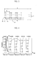
- Fig. 3 is a diagram describing comb symbols each of which is formed of sub-carriers in the frequency domain in accordance with an embodiment of the present invention.
- the sub-carriers of a comb pattern are allocated over the entire available frequency band at the same frequency interval.
- a set of sub-carriers of a comb pattern is referred to as a comb symbol and the sub-carrier set is called a sub-carrier group.
- the reference numerals 30 through 33 indicate comb symbols, respectively.
- the number N s of sub-carriers constituting each of the N c comb symbols can be set up differently according to the data transmission rate requested by the mobile stations. For example, one comb symbol can be formed of four sub-carriers, while another comb symbol can be formed of 64 sub-carriers.
- Fig. 4 is an exemplary diagram illustrating frequency hopping of comb symbols in accordance with an embodiment of the present invention.
- sub-carriers constituting each of two comb symbols 50 and 51 are put apart uniformly over the entire frequency band. This prevents the all sub-carriers from falling in frequency null simultaneously and thus it prevents burst errors. Therefore, the comb symbol frequency hopping method of the present invention has an excellent frequency diversity effect in the transmission of short packets, compared to conventional clustering method.
- the signals for each mobile station can be restored in the receiving system by using partial FFT, which will be described hereafter.
- FFT is one of digital signal processing algorithms implementing discrete Fourier Transform (DFT). It is materialized in the integrated circuit of one or more physical devices to process signals in real-time.
- DFT discrete Fourier Transform
- the FFT is materialized in a FFT unit 233 of Fig. 2 .
- Equation 3 y(n) indicates comb symbols of the time domain received in the receiving system 230, that is, a value obtained by sampling an OFDM signal with a sampling interval T s [second], while y(k) indicates frequency domain signals.
- the sub-carrier interval ⁇ f [ Hz ] is 1/T. Therefore, if the frequency of a sub-carrier is f c [ Hz ], Y(k) is a value at f C + k - N 2 ⁇ ⁇ ⁇ f ⁇ Hz .
- the frequency offset q can be determined to be 0, N c /2* ⁇ f, N c /4* ⁇ f, 3N c /4* ⁇ f, N c /8* ⁇ f, 5N c /8* ⁇ f, 3N c /8* ⁇ f, 7N c /8* ⁇ f, N c /16* ⁇ f, 9N c /16* ⁇ f, 5N c /16* ⁇ f, 13N c /16* ⁇ f, 3N c /16* ⁇ f, 11N c /16* ⁇ f, 7N c /16* ⁇ f, 15N c /16* ⁇ f, ... [Hz] according to the option of a system designer. Therefore, the frequency offset q should be understood not limited to a particular pattern.
- the DFT equation can be reformed by substituting the variables k and n of Equation 3 with the variables p i , q i , r i , and s i which are defined in Equation 4.
- the mobile stations of the receiving system 230 do not require the entire sub-carriers but require only those allocated to each mobile station. Accordingly, if a mobile station processes comb symbols allocated to it only, a variable q i which corresponds to the frequency offset of a mobile station in Equation 5 becomes a constant.
- g(q,s) is DFT operation with respect to N c point, and Y(p, q) can be obtained by multiplying N c complex numbers.
- N, N si and N c is in the shape of 2 n , that is, if they are exponents of 2, FFT can be applied to computation of Y(k).
- FFT can be applied to computation of Y(k).
- performing only part of FFT computation with respect to particular sub-carriers instead of performing entire FFT computation with respect to the entire sub-carriers is called 'partial FFT computation'.
- the amount of FFT computation can be reduced optimally.
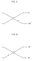
- Figs. 5 and 6 show basic structures of a radix-2 butterfly unit expressed with radix-2 DIF algorithm and radix-2 DIT algorithm, respectively.
- Fig. 5 is a diagram showing the structure of the radix-2 DIF butterfly unit
- Fig. 6 is a diagram illustrating the structure of the radix-2 DIT butterfly unit.
- the butterfly units that form the FFT unit 233 and the IFFT unit 214 are elements that perform the arithmetic operation of Equation 3.
- the butterfly operation of the FFT unit 233 is performed by the data computation of a ⁇ -point, y being a radix.
- An N-point FFT unit includes N/ ⁇ butterfly units at each stage of a log ⁇ N stage. The operation result of one butterfly stage becomes an input to the next butterfly stage.
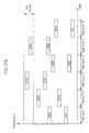
- Fig. 7 is a diagram showing a signal flow of the FFT unit adopting the DIF algorithm
- Fig. 8 is a diagram showing a signal flow of the FFT unit adopting the DIT algorithm.
- Fig. 7 shows the radix-2 FFT unit 233 having the DIF butterfly unit of Fig. 5
- Fig. 8 shows a radix-2 FFT unit 233 having the DIT butterfly unit of Fig. 6 .
- the comb symbols transmitted through the radio signal receiving unit 232 that is, time-domain sample values y(n) of the OFDM symbols are inputted to an input unit 60 of the FFT unit 233 of Fig. 7 in the marked order sequentially.
- y(n) is inputted to the input unit 60 of the FFT unit 233, n being a value selected from 0 to 31.
- the number marked in the input unit 60 indicates a time index, which is n of a signal y(n) to be inputted to a corresponding input terminal, it corresponds with the address of the input unit.
- butterfly computation is performed at each stage. After the butterfly computation at the last stage, a frequency-domain signal Y(k) is stored in an output memory 61 of the FFT unit 233.
- the numbers marked in the output memory 61 are obtained by bit-reversing the addresses of the output memory 61 that are arranged sequentially from zero.
- the numbers are k, which is a frequency index.
- frequency domain signals Y(k) stored in the output memory 61 are grouped according to a predetermined standard based on the memory address sub-carrier groups.
- the numbers are k, which is a frequency index.
- the frequency-domain signals Y(k) stored in the output memory 61 are grouped according to a predetermined standard based on the memory address and form sub-carrier groups. Then, one of the sub-carrier groups closest to the stored memory address is defined as an adjacent group. In Fig. 7 , Y(k) sets grouped in the order of the memory addresses becomes sub-carrier groups.
- the frequency-domain signals Y(k) stored in the output memory 61 are mapped in the order that the addresses of the output memory 61 are bit-reversed so that they have a value in the frequency of the sub-carriers that constitute a comb symbol in the frequency domain 65. Therefore, the frequency-domain signals Y(k) of the sub-carrier groups that are stored in the output memory 61 become sub-carrier signals constituting the comb symbol.
- the addresses of the output memory 61 are formed of five bits in the embodiment of Fig. 7 , that is, in the 32-point FFT unit, the addresses of the output memory 61 and the signals Y(k) obtained by bit-reversing the addresses and transmitted by the sub-carriers f c + k - N 2 ⁇ ⁇ ⁇ f ⁇ Hz constituting comb symbols are mapped as shown in Table 1.
- the frequency domain signals Y(k) stored in the output memory 61 are grouped into each four of them and the sub-carrier groups are expressed as a sub-carrier group a, sub-carrier group b, sub-carrier group c, ..., sub-carrier group h 63.
- the addresses of the output memory 61 are 0, 1, 2, 3, ..., 31, which are shown in Table 1 sequentially. Their bit-reversed sequence is 0, 16, 8, 24, ..., 31.
- the actual frequency domain signals that appear in the sub-carrier group a are Y(0), Y(16), Y(8), and Y(24).
- the actual frequency-domain signals expressed by the sub-carrier group b are Y(4), Y(20), Y(12), and Y(28).
- values corresponding to a sub-carrier group i are frequency domain signals of a comb symbol i.
- the values Y(k) of the sub-carrier group a correspond to a set of sub-carriers that constitutes a comb symbol a 64 in the frequency domain 65.
- time domain signals y(n) are inputted to an input unit 70 of the DIT FFT unit in the marked order.
- values y(n) obtained by bit-reversing the addresses 0 to 31 of the input unit 70 are inputted to the input unit 70 of the FFT unit 233.
- the numbers expressed in the input unit 70 indicate n of the values y(n), which are time indexes, to be inputted through input terminals. Differently from Fig. 7 , the values of Fig. 8 are bit-reversed.
- the addresses of the input unit 70 are formed of five bits, the addresses are mapped to the sub-carriers y(n) obtained by bit-reversing the addresses of the input unit 70 and constituting a comb symbol as shown in Table 2.
- the frequency domain signals Y(k) are stored in an output memory 71 of the FFT unit 233.
- the numbers expressed in the output memory 71 are the addresses of the output memory 71, k denoting a frequency index. Differently from Fig. 7 , those numbers are not bit-reversed.
- Fig. 8 shows the frequency domain signals Y(k) stored in the output memory 71 correspond to the actual frequency band in the sequence that bit-reversion is not performed in the FFT unit adopting the DIT algorithm. Therefore, in the signal flow of Fig. 8 where the DIT algorithm is applied, a set of values Y(k) with a regular space N c stored in the output memory 71 becomes a sub-carrier group.
- a sub-carrier group is defined as what is obtained by bit-reversing the indexes k of the frequency domain signals Y(k) stored in the output memory 71 and grouping the bit-reversed indexes into a predetermined number of them. Also, among the sub-carrier groups stored in the addresses of the output memory, a sub-carrier group having a bit-reversed value closest to the values obtained by bit-reversing the addresses of the output memory 71 becomes an adjacent group.
- the indexes k of the frequency domain signals Y(0), Y(8), Y(16) and Y(24) that are stored in the output memory 71 or values obtained by bit-reversing the addresses of the output memory 71 are 0, 2, 1 and 3 and the four sub-carriers are defined as a group a.
- the indexes k of the frequency domain signals Y(4), Y(20), Y(12) and Y(28) that are stored in the output memory 71 or values obtained by bit-reversing the addresses of the output memory 71 are 4, 5, 6 and 7 and the four sub-carriers are defined as one of the groups adjacent to the group a.
- Figs. 7 and 8 the input and output points for butterfly computation for obtaining the sub-carrier signals Y(0), Y(8), Y(16) and Y(24) of the sub-carrier group a are circled.
- computation is operated partially in the FFT unit to obtain a comb symbol a 64. Therefore, power consumption is reduced remarkably due to the reduced computation.
- the receiving system 230 is aware of the sub-carrier groups it should acquire in advance through the properties of the sub-carrier groups, such as the starting point of a signal, frequency hopping pattern, size of the sub-carrier groups and the like. So, it can determine the input and output points for butterfly computation for obtaining sub-carrier signals Y(k) in advance.
- the butterfly computation is operated as shown in Figs. 7 and 8 . Thus, the amount of computation can be reduced by performing partial FFT to restore the sub-carrier signals of a comb symbol in the receiving system 230.
- IFFT computation should be operated in an IFFT unit 214.
- the computation amount of the IFFT unit can be reduced by allocating the sub-carriers in the form of comb symbols.
- the IFFT computation is operated in the FFT unit.
- time domain signals x(n) are obtained by switching the real number portion and the imaginary number portion of the frequency domain signals X(k), inputting the resultant values to input units 60 and 70 of the FFT unit, operating butterfly computation at each stage, and then switching again the real number portion and the imaginary number portion of the output values obtained in output memories 61 and 71.
- Fig. 9 shows an embodiment where the IFFT computation is operated using radix-2 DIF algorithm of Fig. 5 .
- frequency domain signals X(0), X(16), X(8), and X(24) which are sub-carrier signals X(0), X(16), X(8), and X(24) that form a comb symbol a 84, are inputted to corresponding terminals of the IFFT unit 214 whose addresses are 0, 8, 16 and 24.
- null (0) signals are inputted.
- the input and output points for butterfly computation for obtaining time domain sub-carrier signals x(0) to x(31) are circled.
- Fig. 9 in case ⁇ 0' is inputted to two input terminals of butterfly and butterfly computation is kept from being operated, the butterfly computation is operated as shown in the input and output points of Fig. 9 .
- the sub-carrier signals X(0), X(8), X(16), and X(24) form the comb symbol a 84.
- the sub-carrier signals X(0), X(8), X(16), and X(24) are inputted to the IFFT unit 214 by mapping a data sequence transmitted from the transmitting system 210 of Fig. 2 to complex numbers through the modulation unit 211, receiving comb symbols formed of four sub-carriers allocated thereto through the sub-carrier allocating unit 212 based on the transmission rate of the data sequence, and performing the frequency hopping on the sub-carriers according to a given pattern along each time slot in the frequency hopping unit 213.
- a method for allocating comb symbols to mobile station without frequency collision will be describer later.
- Fig. 8 shows that time domain signals y(n) are inputted, and four frequency domain signals Y(k) constituting the comb symbol a are outputted.
- Fig. 9 shows that the four frequency domain signals X(k) constituting the comb symbol a are inputted and the time domain signals x(n) are outputted to an output memory 81.
- the computation amount of the IFFT unit can be reduced. This leads to reduction in the computation amount of the transmitting system 210.
- the comb symbol-based frequency hopping of the present invention makes the frequency offset 65 of the comb symbols differ in the frequency band according to the frequency hopping between sub-carrier groups. For example, in Fig. 7 , a sub-carrier group a is allocated as sub-carriers of a comb symbol. If the frequency of the sub-carrier group a hops to an adjacent sub-carrier group b, the frequency offset is changed from a comb symbol a to a comb symbol b in the frequency domain.
- frequency hopping is performed between sub-carrier groups. So, the sub-carriers allocated after frequency hopping are always different from the sub-carriers allocated in the preceding time slot.
- Fig. 10 is a diagram illustrating comb symbols, which are allocated to one mobile station, performing frequency hopping to an adjacent sub-carrier group in accordance with an embodiment of the present invention.
- Fig. 11 is a diagram describing comb symbols, which are allocated to one mobile station, performing frequency hopping randomly in accordance with an embodiment of the present invention.
- Fig. 10 shows a pattern the sub-carrier group of one comb symbol performs frequency hopping to an adjacent sub-carrier group
- Fig. 11 presents a pattern the sub-carrier group of one comb symbol performs frequency hopping randomly.
- the random frequency hopping pattern includes a frequency hopping pattern having an identical frequency offset, which is a case where frequency hopping does not occur substantially in the frequency band. This is possible by establishing an independent frequency offset according to time.
- the frequency offset of comb symbols is different in the frequency band according to the frequency hopping between sub-carrier groups.
- the boxes marked as sub-carrier groups Y(k) on the left part of Figs. 10 and 11 are the sub-carrier groups a, b, c, ... 63 of Fig. 7 .
- the comb symbol formed of the adjacent sub-carrier group performs frequency hopping in accordance with the embodiment of the present invention.
- the frequency hopping is not carried out to the comb symbol of the adjacent frequency but it occurs in a complex pattern. This acts as a positive factor for increasing the frequency diversity effect based on frequency hopping.
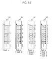
- Fig. 12 shows the sub-carriers of which the positions are changed in the frequency domain due to the additional allocation of comb symbols caused by the increase in the transmission rate.
- Fig. 12 is a diagram depicting sub-carriers changing their positions in the frequency domain, when comb symbols are allocated additionally in accordance with the embodiment of the present invention. It shows a pattern 90 of a comb symbol a when a sub-carrier group a is allocated, a pattern 91 of a combination of the comb symbol a and a comb symbol b when the sub-carrier b is allocated in addition to the sub-carrier a, a pattern 92 of a combination of the comb symbol a, the comb symbol b and a comb symbol c when the sub-carrier group a, the sub-carrier group b, and a sub-carrier group c are allocated, and a pattern 93 of a combination of the comb symbol a, the comb symbol b, the comb symbol c and a comb symbol d when the sub-carrier group a, the sub-carrier group b, the sub-carrier group c and a sub-carrier group d are allocated
- the space between the sub-carriers of a comb symbol is decreased.
- the space between the sub-carriers constituting the comb symbols may not be the same but depends on the frequency offset of the comb symbols.
- the initial comb symbol is not the comb symbol a but a comb symbol having another frequency offset
- the sub-carrier allocation pattern that is changed according to the increasing transmission rate and the additional allocation of other comb symbols is different from that of Fig. 12 .
- the initial comb symbol allocated to the mobile terminal is the comb symbol b and then the comb symbols c, d and a are allocated additionally, the sub-carrier allocation pattern appears differently from that of Fig. 12 .
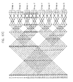
- Fig. 13 is a diagram describing the amount of computation which should be performed in a butterfly unit for the FFT unit adopting a DIF algorithm to yield neighboring sub-carrier groups in accordance with an embodiment of the present invention.
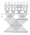
- Fig. 14 is a diagram illustrating the amount of computation which should be performed in a butterfly unit for the FFT unit adopting a DIF algorithm to yield un-neighboring sub-carrier groups in accordance with an embodiment of the present invention.
- Figs. 13 and 14 which show signal flow in the FFT unit 233, presents an embodiment where two comb symbols of the same size are allocated to one mobile station to double the transmission rate.
- a comb symbol of an adjacent sub-carrier group is allocated in accordance with the present invention.
- Fig. 14 shows a case where a comb symbol of a sub-carrier group that is not an adjacent sub-carrier group is allocated. From the two drawings, it can be seen that the technology of the present invention where a comb symbol of an adjacent sub-carrier group is allocated is superior to that of Fig. 14 .
- the dot-lined boxes 122 and 132 denote the amount of computation consumed additionally by the comb symbols allocated additionally.
- a comb symbol of a sub-carrier group a and a comb symbol of an adjacent sub-carrier group b 121 are allocated to one mobile station, only a little amount of computation is consumed additionally.
- the sub-carriers of the comb symbol a 123 and the comb symbol b 124 that belongs to an adjacent sub-carrier group do not appear adjacently but they are put apart with a regular space in the frequency band.
- Fig. 14 shows a case where comb symbols of a sub-carrier a 130 and a sub-carrier e 131 that are not adjacent sub-carrier groups are allocated to one mobile station.
- the increase 132 in the butterfly computation amount for obtaining a signal of the additional sub-carrier group e 131 is larger than the increase 122 in the computation of Fig. 13 .
- the computation amount can be decreased more by additionally allocating a comb symbol of an adjacent sub-carrier group than allocating a comb symbol of a sub-carrier group which is not an adjacent sub-carrier group.
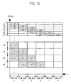
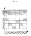
- Fig. 15 is a diagram showing comb symbols, each of which is formed of a different number of sub-carriers, being allocated to many mobile stations within a cell of a base station and performing frequency hopping to adjacent sub-carrier groups of the same size in accordance with an embodiment of the present invention. It shows an example of a pattern that a comb symbol of a sub-carrier group performs frequency hopping to a comb symbol of an adjacent sub-carrier group.
- the horizontal axis indicates time slots, while the vertical axis shows sub-carrier group. It should be noted that the vertical axis shows sub-carrier group, which is different from Fig. 1A .
- the sub-carrier groups performs frequency hopping to adjacent comb symbols without any overlapping.
- interference can be prevented between the mobile stations in a cell.
- Fig. 15 shows an example where the number of sub-carriers constituting an allocated comb symbol is different according to the type of data.
- the sub-carrier groups formed having a few number of sub-carriers are a1, b1 and c1 and those having many sub-carriers, for example, 64 sub-carriers, are a2, b2 and c2. If the number of sub-carriers constituting a comb symbol is the size of the comb symbol, it is proper to allocate comb symbols of small size to data signals having short packets, such as voice signals or control signals and allocate comb symbols of large size to signals requiring high transmission rates.
- the computation amount of partial FFT can be minimized by grouping the sub-carriers a1, b1 and c1 constituting the comb symbol of small size, e.g., 4 sub-carriers, as one group and grouping the sub-carriers a2, b2 and c2 constituting the comb symbol of large size e.g., 64 sub-carriers, as another group and then making the sub-carrier groups perform frequency hopping to sub-carrier groups of the same size in the process for allocating comb symbols and determining a frequency hopping pattern.
- the frequency hopping can be carried out only between the comb symbols of the same size, that is, within the sub-carrier groups that form allocated comb symbols.
- the frequency hopping is performed between comb symbols having the same size but different frequency offsets. This way, the computation amount of partial FFT can be minimized.
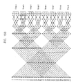
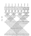
- Figs. 16A to 16D are diagrams describing partial FFT computation based on the frequency hopping pattern of a comb symbol, which is formed of a group of sub-carriers, in accordance with an embodiment of the present invention.
- Figs. 17A to 17D and 18A to 18D are exemplary diagrams describing the computation of partial FFT according to the frequency hopping pattern when two or more comb symbols are allocated to one mobile station.
- Figs. 16A to 16D show signal flow of the FFT unit adopting the DIF algorithm according to the frequency pattern, when the size of the sub-carrier group is 4, i.e., when the comb symbol is formed of four sub-carriers.
- the four drawings are discriminated according to time slots and the frequency hopping pattern is carried in the order of sub-carrier groups a -> b -> c -> d.
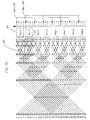
- Figs. 17A to 17D show signal flow of the FFT unit adopting the DIF algorithm according to frequency hopping pattern, when two comb symbols of the same size are allocated due to increase in the transmission amount.
- the four drawings are discriminated according to time slots and the frequency hopping pattern is carried in the order of sub-carrier groups (a,b) -> (b,c) -> (c,d) -> (d,e).
- the FFT computation amount can be decreased and thus the frequency diversity can be increased by establishing the minimum unit for frequency hopping as the size of the comb symbol allocated initially and changing the space between sub-carriers through frequency hopping.
- the minimum unit for frequency hopping is determined to be a summation of the sizes of two sub-carrier groups.
- the frequency hopping is performed in the order of the sub-carrier groups (a,b) -> (c,d) -> (e,f) -> (g,h). That is, if i comb symbols are allocated to one mobile station, the minimum unit for the frequency hopping of the comb symbols is established as the number of sub-carriers that forms the i comb symbols.
- Figs. 18A to 18D it can be seen that the number of butterflies required for computation according to time slots, i.e., computation amount, is the same when comb symbols are allocated additionally and frequency hopping is carried out.
- the sub-carriers are placed based on the comb symbol.
- groups a, b, c and the like acquire group numbers corresponding thereto, such as groups 0, 1, 2 and the like, sequentially and the group number of the sub-carrier group allocated initially is g n , the frequency hopping is performed to a sub-carrier group G according to the frequency hopping pattern function P(l) shown in Equation 6.
- the unit of the frequency hopping is the summation of the sizes of the sub-carrier groups allocated to the mobile station.
- the allocation and frequency hopping of the comb symbols are performed within the sub-carrier groups having the same size.
- the computation amount of partial FFT is minimized.
- the frequency diversity effect can be maximized by changing the space between the allocated sub-carriers.
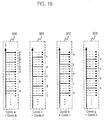
- Fig. 19 illustrates the frequency hopping of Figs. 18A to 18D in the frequency band.
- Fig. 19 describes the change in the space between the sub-carrier groups in the frequency band when a comb symbol is allocated additionally and thus two sub-carrier groups performs frequency hopping.
- a time slot 1 of Fig. 18A is the reference number 300 of Fig. 19 and a time slot 2 of Fig. 18B is the reference number 301 of Fig. 19 .
- a time slot 3 of Fig. 18C is the reference number 302 of Fig. 19 and a time slot 4 of Fig. 18D is the reference number 303 of Fig. 19 .
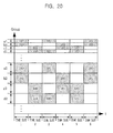
- Fig. 20 is an exemplary diagram illustrating comb symbols, each including four sub-carriers, being allocated to many mobile stations within a cell and performing frequency hopping randomly in accordance with an embodiment of the present invention.
- a transmission amount is increased, an adjacent sub-carrier group is allocated additionally to form a comb symbol.
- the frequency hopping is carried out randomly, the advantage of calculating partial FFT can be revealed.
- Fig. 20 shows sub-carrier groups, each formed of the same number of sub-carriers, being allocated and performing frequency hopping among the sub-carrier groups of the same size. For example, if comb symbols of the size 182 and the size 183 are allocated and perform frequency hopping, the comb symbol allocation and the frequency hopping are carried out among the sub-carrier groups a1, b1, c1 and d1. In case that the comb symbols having the sizes 180 and 181 are allocated and performed frequency hopping, the comb symbol allocation and frequency hopping are performed among the sub-carrier groups a2, b2, c2 and d2.
- the interference between the mobile stations within the cell can be removed.
- the frequency hopping patterns of comb symbols are different between the mobile stations, the interference between cells can be equalized without additional frequency allocation. That is to say, neighboring cells may use the same frequency in one time slot by chance.
- the interference between the cells is leveled, which leads to decreasing the interference affected on one mobile station.
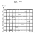
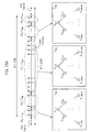
- Fig. 21 is a diagram showing an arrangement of cells and Figs. 22A to 22G are diagrams describing an example of a hopping pattern for reducing inter-cell interference in accordance with an embodiment of the present invention.
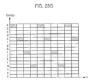
- Figs. 23A to 23G are diagrams describing an example of a hopping pattern for reducing inter-cell interference in accordance with an embodiment of the present invention.
- a sub-carrier group at the top of the y axis is a sub-carrier group a, followed by sub-carrier groups b, c, d, e, f, g, h, i, j, k, l, m, n, o, and p in the mentioned order.
- the x axis shows time slots.
- Fig. 22A shows a frequency hopping pattern established in a cell A and Fig. 22B shows a frequency hopping pattern established in a cell B.
- the frequency hopping to adjacent sub-carrier groups begins with the sub-carrier group a, followed by the sub-carrier groups b, c, d, e, f, g, h, i, j, k, l, m, n, o, and p in the mentioned order.
- Fig. 22A shows a frequency hopping pattern established in a cell A
- Fig. 22B shows a frequency hopping pattern established in a cell B.
- the frequency hopping to adjacent sub-carrier groups begins with the sub-carrier group a, followed by the sub-carrier groups b, c, d, e, f, g, h, i, j, k, l, m, n, o, and p in the mentioned order.
- Fig. 22A shows a frequency
- the frequency hopping to adjacent sub-carrier groups begins with the sub-carrier group a, followed by the sub-carrier groups c, e, g, i, k, m, o, and p in the mentioned order. That is, the frequency hopping is performed to a next adjacent sub-carrier group that comes after one adjacent sub-carrier.
- Figs. 22C though 22G also show patterns of frequency hopping performed jumping over some sub-carrier groups.
- different frequency hopping patterns are established for cells A to G, which are presented in Figs. 22a to 22G , by making the direction of the frequency hopping the same and making the hopping space different.
- Fig. 23A shows a frequency hopping pattern established in the cell A and Fig. 23C shows a frequency hopping pattern established in the cell C.
- Fig. 23E shows a frequency hopping pattern established in the cell E and
- Fig. 23G shows a frequency hopping pattern established in the cell G.
- the frequency hopping patterns of Figs. 23A , 23C , 23E and 23G are the same as those of Fig. 22A, 22B , 22C and 22D , respectively.
- Fig. 23B presents a frequency hopping pattern of a cell B where the frequency hopping begins with the sub-carrier group p, which is in the lowest position, and is performed in the reverse direction.
- Fig. 23D presents a frequency hopping pattern of a cell D where the frequency hopping begins with the sub-carrier group p and is performed in the reverse direction, jumping over one adjacent sub-carrier group. That is, different frequency hopping patterns are generated by changing shifting spaces and directions and then allocated. If the frequency hopping patterns described above are used, the probability of using the same frequency in the cells can be minimized, thus reducing inter-cell interference.
- the frequency hopping pattern 1 of Fig. 22A and the frequency hopping pattern 2 of Fig. 22B are described herein.
- Both frequency hopping patterns 1 and 2 have the same shifting direction according to time slots, but they are different in that the sub-carrier groups of the pattern 1 shift to their adjacent sub-carrier groups and the sub-carrier groups of the pattern 2 shift to the next adjacent sub-carrier groups after jumping over one sub-carrier group.
- the number of the entire sub-carrier groups is Ng and the frequency hopping period is N h
- the number of sub-carrier groups that can be used for one frequency hopping period is Ng X N h . If each user is assumed to receive only one sub-carrier group, the number of users that can perform multiple access in one cell is Ng.
- a sub-carrier group positioned at the top of the y axis, which shows sub-carrier groups, is referred to as a group 0 and the sub-carrier groups that come below the group 0 is referred to as groups 1, 2, 3,..., N g -1.
- the entire sub-carrier groups are defined as groups 0 to Ng-1.
- a user to which a group u is allocated is defined as a user u.
- the number of groups that act as interference on the cell A during one frequency hopping period is N h . Since the cell A uses all sub-carrier groups, it is inevitable that the sub-carrier groups of the two cells are overlapped as many as the number of sub-carrier groups used in the cell B. The number of sub-carrier groups that act as interference on the users of the cell A is N g /N h in average.
- the number of groups acting as interference is an integer. Therefore, the number of groups acting as interference for each user of the cell A may be different based on the N g and N h . In other words, the number of the groups overlapped between the user of the cell A and the one user of the cell B can be different according to the Ng and N h . For example, if the cell B adopts the frequency hopping pattern 2 and the sub-carrier group allocated to the user of the cell B in the initial slot is the group 0, the number of overlapped sub-carrier groups for the user u of the cell A is (i+1), when it satisfies the condition of Equation 7.
- the frequency hopping patterns of Figs. 23A to 23G are described as follows. Here, it is assumed that the cell A uses the frequency hopping pattern 1 of Fig. 23A and the cell B uses the frequency hopping pattern 2 of Fig. 23B . Other conditions remain the same as the aforementioned examples.
- N g 2z+1
- N g 2 + i ⁇ N g 2 - m ⁇ N h ⁇ N g 2 + i + 1 ⁇ N g 2 - m i 0 , 1 , 2 , ...
- the inner-cell "and/or inter-cell frequency hopping patterns described with reference to Figs. 22A to 22G and 23A to 23G need not be combined with other technological properties of the present invention necessarily. This is because the effect of frequency diversity and the effect of reduced FFT computation amount can be brought about with the technological properties of comb symbol allocation and frequency hopping of the present invention alone. Also, the inner-cell and/or inter-cell frequency hopping pattern shown in Figs. 22A to 22G and 23A to 23G have an additional effect of minimizing inter-cell interference and preventing interference between mobile stations within a cell.
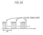
- Fig. 24 which is a diagram illustrating arrangement of pilot signals, provides an example of pilot signal arrangement in an OFDM system for estimating a channel or a synchronization unit.
- pilot signals are defined as signals that are transmitted along with data signals among the signals for control, signals necessary for all users, and signals for estimating a channel.
- the pilot signals 2100 are arranged at the same intervals over the entire frequency band. This is the same as the comb symbols defined in the present invention for data transmission. So, the method of the present invention can be applied directly.
- the pilot signals 2100 are regarded as one comb symbol that is fixed and does not perform frequency hopping according to time slots. Then, channel information on the entire frequency band can be obtained with a small amount of computation by using only the sub-carriers corresponding to the pilot signals and performing partial FFT in the receiving system 230.
- the channel information can be obtained with a least power consumption by performing partial FFT on the comb symbol corresponding to the pilot signals 2100 and the comb symbols allocated to mobile stations in all receiving system 230.
- pilot signals are required by all mobile stations, it is desirable to allocate the pilot signals to comb symbols that can be obtained by consuming a least amount of power.
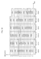
- Table 3 shows computation amounts needed for each comb symbol to obtain a comb symbol having a least amount of computation.
- the computation amounts of complex number summation and complex number multiplication required to each comb symbol are presented for comparison.
- the number N of the entire sub-carriers is 2,048 and the number N c of symbols of a comb is 16 and the number N s of sub-carriers allocated to each comb symbol is 128.
- a, b, ..., p expressed as a comb are the sub-carrier groups a, b, ..., p stored in the output memory 61 of the FFT unit 233 of Fig. 7 .
- the pilot signals should be allocated and perform frequency hopping sequentially according to a priority order from a comb symbol with the least number of complex number multiplication, that is, from a comb symbol including a sub-carrier stored in an address 0 of the output memory. Otherwise, the computation amount for obtaining channel information becomes the least in all mobile stations.
- the comb symbols should be allocated according to the required number of pilot signals, but the selection priority should be given to a comb symbol including a sub-carrier stored in the address 0 of the output memory, followed by a comb symbol including a sub-carrier stored in the address of the next smallest value.
- the priority is established in the order of a comb a, a comb b, ... in Fig. 7 . If there are a plurality of pilot signals to be allocated, the pilot signals are allocated according to the priority order determined in the above and transmitted to mobile stations.
- Fig. 25 is a diagram describing the frequency hopping of a sub-carrier group allocated for a pilot signal and that of a sub-carrier group allocated for a data signal in accordance with an embodiment of the present invention. It shows an example where a sub-carrier group a1 is allocated to a pilot signal 2300. The pilot signal 2300 does not perform frequency hopping according to time slots and are allocated to the sub-carrier group a1 all the time. On the other hand, data signals 2301 and 2302 perform frequency hopping along the time slots based on a given frequency hopping pattern.
- All mobile stations perform partial FFT only on the pilot signals 2300 of the sub-carrier group a1 and the comb symbols allocated to them in the receiving system 230 to thereby obtain channel and synchronization information and transmitted data.
- the sub-carriers of the sub-carrier group are allocated in the form of comb symbols actually, and the frequency hopping of the sub-carrier group is frequency hopping to a comb symbol having a different frequency offset actually.
- Described in the above is a technology of allocating to mobile stations comb symbols, which are sub-carrier groups dispersed at predetermined intervals over the entire frequency band and performing frequency hopping.
- comb symbols are formed in a tree structure.
- the comb symbols, sub-carrier resources, are allocated dynamically.
- a method for allocating the tree-structured sub-carrier resources to mobile stations will be described.
- Fig. 26 is a diagram illustrating a method for allocating comb symbol resources by forming the comb symbols in a tree structure in accordance with an embodiment of the present invention.
- the number N of sub-carriers in the entire frequency band and the number Ns of sub-carriers constituting a comb symbol are powers of 2 and the comb symbols are formed in a tree structure.
- the comb symbol resources are allocated based on the tree structure in a cell as follows.
- the comb symbols are formed in a tree structure where the numbers N s of the sub-carriers constituting the comb symbols are 1, 2, 4, ..., 2 n .
- the comb symbols are expressed based on Equation 2. In case the frequency index k needs not be discriminated, it is omitted hereinafter.
- a comb symbol X 1,0 at a root node is formed of 2 n sub-carriers.
- the root node comb symbol X 1,0 includes comb symbols X 2,0 and X 2,1 , each of which is formed of 2 n-1 sub-carriers.
- a comb symbol X 2 é , b which is formed of 2 n-a sub-carriers and has a frequency offset b includes comb symbols X 2 e-1 , b and X 2 e -1 . b +2 a , each of which is formed of 2 n - a -1 sub-carriers and the frequency offset is b and b +2 a , respectively.
- N s 1,2,4,...,2 n , n being an integer
- X a,b is not a parent node of X c,d
- the OFDMA system can use null carriers due to the implementation of filters in the transmitting end or receiving end. So, the number of sub-carriers that can carry actual data may not be a power of 2.
- the comb symbols are formed into the tree structure of Fig. 26 and allocated according to the tree and, also, the data are transmitted after shifted or punctured because the positions of the data corresponding to the null carriers can be know in advance.
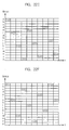
- Fig. 27A is a diagram describing a data transmission method without loss in the data transmission rate by puncturing data corresponding to null carriers in accordance with an embodiment of the present invention.
- data are transmitted after null data are inserted to the data at positions corresponding to the null carriers.
- the comb symbols are formed into a tree structure when the number N of the entire sub-carriers is an arbitrary integer and the number Ns of sub-carriers constituting a comb symbol is not a power of 2, and the comb symbols are allocated according to the tree structure in a cell.
- Fig. 27A shows an example where comb symbols, each having two sub-carriers, are allocated and perform frequency hopping.
- the reference numerals 3000 through 3011 are data to be transmitted.
- the data 3004 and 3008 correspond to null carriers. So, they are punctured and not transmitted actually. Since the data are punctured and transmitted, the data transmission rate is the same as a case where no null carrier exists. The punctured data can be restored during the decoding of an error correction code in the receiving end.
- Fig. 27B is a diagram depicting a data transmission method without data loss by shifting data corresponding to null carriers in accordance with an embodiment of the present invention.
- data are transmitted after null data are inserted to the data at positions corresponding to the null carriers.
- the comb symbols are formed into a tree structure when the number N of the entire sub-carriers is an arbitrary integer and the number Ns of sub-carriers constituting a comb symbol is a power of 2, and the comb symbols are allocated according to the tree structure in a cell.
- Fig. 27B shows an example where comb symbols, each having two sub-carriers, are allocated and perform frequency hopping.
- the reference numerals 3000 through 3009 are data to be transmitted. Since the initial position and hopping pattern of the comb symbols are known in the transmitting end, null data are inserted to null carriers and the data corresponding to the null carriers are shifted and moved to sub-carriers for carrying the next data and transmitted.
- the present invention also includes combinations of the methods illustrated in Figs. 27A and 27B .
- Figs. 28A and 28B are diagrams illustrating a method for allocating symbol resources of a comb pattern by forming the symbols in a multi-tree structure in accordance with an embodiment of the present invention.
- comb symbols are formed in a multiple-tree structure and allocated according to the multiple-tree in a cell, when the N'-point FFT is used and the number N of the sub-carriers in the entire frequency band is not a power of 2.
- Figs. 28A and 28B and Equation 11 show that the comb symbols of different sub-tree nodes are orthogonal to each other. Therefore, comb symbols formed of many sub-carriers can be allocated to mobile stations without frequency collision by applying the method of Fig. 26 to each sub-tree and allocating frequency resources.
- the data corresponding to null carriers can be transmitted after punctured and shifted using the methods of Figs. 27A and 27B .
- the entire frequency band including N sub-carriers is divided into M sub-bands formed of consecutive sub-carriers. Then, N/M-point FFT is used in each sub-band to reduce the computation amount of the mobile stations and/or base stations.
- the FFT computation amount of the mobile stations can be reduced by forming the sub-carriers of each sub-band into a tree structure of comb symbols, extending the tree structure to form a multiple-tree including the sub-trees on the entire frequency band, and allocating the sub-carriers in one or more sub-bands to the mobile stations during the comb symbol allocating process.
- sub-carriers of arbitrary sizes in one or more sub-bands are allocated to mobile stations during the comb symbol allocation process by dividing N sub-carriers in the entire frequency band into M sub-bands and building a multiple tree including comb symbol sub-trees, each sub-tree formed with respect to each sub-band, in the entire frequency band.
- the allocated sub-carriers perform frequency hopping on a sub-band basis. This way, adaptive modulation can be performed based on each frequency band. Since FFT computation is operated with respect to the number N/M of sub-carriers of each sub-band, the amount of computation can be reduced.
- comb symbols each having Nr sub-carriers are allocated to the mobile stations.
- comb symbols X st 1 Nc 1 . q 1 , ⁇ X st m , Nc m . q m extracted from a plurality of sub-trees are allocated to have the same frequency interval while maintaining N c i at a fixed value.
- comb symbols that are extracted from two adjacent sub-trees and whose interval between the frequencies at both ends is the same as the interval between the two comb symbols are allocated.
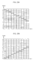
- Fig. 29 is an exemplary diagram showing 352 sub-carriers allocated to one mobile station in the multi-tree structure of Fig. 28A .
- the sub-trees are allocated to a sub-tree 1, a sub-tree 3, and a sub-tree 5. Then, the comb symbols having the same frequency interval are allocated to thereby minimize the amount of partial FFT computation.
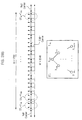
- Fig. 30 is a diagram describing a frequency hopping method where all comb symbols of a cell perform frequency hopping in the frequency domain according to a frequency hopping pattern to thereby avoid collision between the symbols having different size. It explains a method of performing orthogonal frequency hopping on the comb symbols allocated to the mobile stations of a cell in the frequency area through the methods of Figs. 26 , 28A , 28B and 28C .
- the amount of partial FFT computation at the receiving end can be minimized by using the methods of Figs. 15 and 20 .
- the requests of orthogonal frequency hopping and minimization of partial FFT computation amount can be satisfied, if the frequency hopping is not performed among the sub-carrier groups having the same size as a sub-carrier group constituting a comb symbol of arbitrary size allocated to a mobile station.
- Equation 12 Data are transmitted and frequency hopping is performed based on Equation 12, Y a,b ( k ; l ).
- the number of the entire sub-carriers is 16 and a comb symbol X 8,1 is allocated to 3100; X 4,2 , to 3101; X 4,0 , 3102; and X 8,7 , 3103, according to the method of Fig. 26 .
- It shows a frequency hopping pattern P ( l ) 0,7,13,3,9,2, ⁇ , of the comb symbols according to time based on Equation 12.
- inter-cell interference can be leveled by allocating a different frequency hopping pattern in a different cell.
- the method of the present invention can be materialized in the form of a program and stored in a computer-readable recording medium, such as CD-ROMs, RAMs, ROMs, floppy disks, hard disks and magneto-optical disks.
- a computer-readable recording medium such as CD-ROMs, RAMs, ROMs, floppy disks, hard disks and magneto-optical disks.
- frequency hopping is performed in the frequency domain on a cluster basis.
- Clusters are obtained by organizing sub-carriers into groups based on proximity.
- the method of the present invention can increase frequency diversity and enhance interference leveling effect during transmission of short packets by performing frequency hopping on comb symbols in the frequency domain.
- the comb symbols are formed of' sub-carriers that are apart at predetermined frequency intervals over the entire frequency band.
- the use of different frequency hopping pattern makes a comb symbol hop into a different sub-carrier always.
- the present invention has another advantage that it can minimize power consumption by restoring only a part corresponding to a comb symbol allocated to each mobile station through partial FFT.
- the power consumption can be minimized by performing IFFT with the same computation amount as the partial FFT by not computing when butterfly inputs are all zero in the transmitting system of a mobile station or a base station.
- frequency hopping is performed as comb symbols for carrying data are selected differently according to each time slot.
- the frequency hopping patterns includes a pattern having a regular rule, for example, a pattern where sub-carriers are shifted to adjacent sub-carriers based on the time slots, and a pattern where frequency hopping is performed randomly.
- All the mobile stations of a cell prevent inter-cell interference by not overlapping the frequency hopping in each time slot. If each mobile station has a different transmission rate due to a different service type, the size of a comb symbol is defined differently in proportion to the transmission rate. For addition of comb symbols, additional comb symbols are formed by grouping sub-carriers into adjacent ones. Through the process, the amount of partial FFT can be minimized.
- the amount of partial FFT computation can be minimized by performing frequency hopping on a sub-carrier group basis. Even when sub-carrier groups are allocated additionally, the amount of FFT computation can be reduced by performing frequency hopping based on an existing sub-carrier group.
- the frequency diversity effect can be enhanced. During the process, the frequency diversity effect can be enhanced by changing the interval between the allocated sub-carriers.
- the interference between neighboring cells is leveled without extra frequency allocation by unifying the frequency hopping pattern of all comb symbols allocated within a cell and differentiating the frequency hopping pattern between cells.
- Pilot signals for estimating a channel or synchronization unit are given in the form of a comb symbol. So, it is possible to acquire information on the entire frequency band with a small computation amount by performing partial FFT in the receiving system.
- the comb symbol allocating a pilot signal gives a priority to a top sub-carrier group that can perform restoration with the least amount of computation among all available sub-carrier groups and does not perform frequency hopping. Then, all the mobile stations can acquire channel information with the least amount of computation. If the frequency hopping is performed on the pilot signal, the effect of frequency diversity can be obtained and more accurate channel information can be acquired.
- the comb symbols having orthogonality and suitable for diverse data transmission rate are formed into a tree structure or a multiple tree structure and allocated dynamically.
- the entire frequency bands formed of N sub-carriers are divided into sub-bands, each formed of M consecutive sub-carriers.
- the sub-carriers in each sub-band are formed into a tree structure of comb symbols and a multiple tree including such a sub-tree as a sub-tree is formed on a basis of the entire frequency band.
- the FFT computation amount can be reduced by allocating sub-carriers of arbitrary size in one or more sub-bands to mobile stations and using N/M-point FFT in each sub-band.
- Adaptive modulation can be performed in each frequency band by performing the frequency hopping on a sub-band basis.
Claims (31)
- Verfahren zum Durchführen von Frequenzsprung-Orthogonal Frequency Division Multiple Access, OFDMA, dadurch gekennzeichnet, dass es die Schritte umfasst:a) Zuweisen von Frequenzdomainsignalen X(k) eines Kammmusters zu einer modulierten Datensequenz, wobei X(k) Kammsymbole sind und k ein Frequenzindex ist;b) Durchführen eines Frequenzsprungs derart, dass die Kammsymbole einen unabhängigen Frequenzabsfiand haben können; undc) Durchführen von inverser schneller Fourier-Transformation, FFT, auf den zu Zeitdomainsignalen x(n) zu transformierenden Kammsymbolen und Übertragen der Zeitdomainsignale x(n), wobei n ein Zeitindex ist,wobei die Kammsymbole, welche aus einer vorbestimmten Zahl von Unterträgern gebildet sind, die eine Unterträgergruppe heißt, auf einem gesamten verwendbaren Frequenzband in vorbestimmten Intervallen angeordnet sind und die Zahl von Unterträgern auf der gesamten verwendbaren Frequenz ausgedrückt ist als:
 wobei NC die Zahl von Kammsymbolen bezeichnet, welche in dem gesamten verwendbaren Frequenzband zugewiesen werden können;Nsi die Zahl von Unterträgern innerhalb eines i-ten Kammsymbols, die Größe des i-ten Kammsymbols oder die Größe einer Unterträgergruppe bezeichnet, welche das i-te Kammsymbol bildet, und
und
wobei in Schritt b) ein Frequenzsprung auf Kammsymbolen Xa,b (k) durchgeführt wird, die an die Mobilstation in der Zelle in Übereinstimmung mit einer Frequenzindikatorfunktion Ya,b (k;l) zugewiesen werden, welche ein Frequenzsprungmuster ist und ausgedrückt wird als: wobei P(l) mit 0 ≤ P(l) ≤ N ein Frequenzsprungmuster von Kammsymbolen innerhalb einer Zelle in einem Zeitschlitz 1 ist,N die gesamte Zahl von Unterträgern bezeichnet, unda, b Unterträgergruppen bezeichnen.
 - Verfahren nach Anspruch 1, wobei, falls N Unterträger vorhanden sind und N eine Potenz von 2 ist, N = 2" , wobei n ein Integer ist, der nicht negativ ist, der Schritt a) die Schritte enthält:a1) Bilden eines Kammsymbolbaums T 2 n , welcher aus 1 bis 2 n Unterträgern gebildet ist, wobei ein Kammsymbol X 1,0, welches 2 n Unterträger aufweist, ein Elternknoten ist und ein Kammsymbol X 2
a ,b, welches 2 n-a Unterträger aufweist und welches einen Frequenzabstand b aufweist, X 2a-1 ,b und X 2a-1 ,b+2a als Kindknoten enthält, welche jeweils 2 n-a-1 Unterträger aufweisen und welche einen Frequenzabstand b beziehungsweise b+2 a aufweisen, und ein Kammsymbol, welches einen Unterträger aufweist, ein Endknoten ist; unda2) Zuweisen von Kammsymbolen, welche eine geeignete Größe für eine Übertragungsrate aufweisen, die durch eine Mobilstation angefordert wird, an die Mobilstation und Verhindern von Kollision zwischen den Kammsymbolen durch Nichtzuweisen von Kammsymbolen, welche Kindknoten der Kammsymbole in dem Baum T 2 n entsprechen, an die anderen Mobilstationen in der Zelle, zu welcher die Mobilstation gehört, bis die Kammsymbole, welche die geeignete Größe aufweisen, von der Zuweisung freigegeben werden. - Verfahren nach Anspruch 2, wobei, falls die Zahl von Unterträgern, welche Daten tragen können, auf Grund des Vorhandenseins von Nullträgern unter den N Unterträgern in dem gesamten verwendbaren Frequenzband keine Potenz von 2 ist, wobei N eine Potenz von 2 ist, ein Teil der Daten, welche den Nullträgern entsprechen, in Schritt a) durchschlagen.
- Verfahren nach Anspruch 2, wobei, falls die Zahl von Unterträgern, welche Daten tragen können, auf Grund des Vorhandenseins von Nullträgern unter den N Unterträgern in dem gesamten verwendbaren Frequenzband keine Potenz von 2 ist, wobei N eine Potenz von 2 ist, jeglicher Verlust in der Datenübertragungsrate durch Einfügen von Nulldaten in die Daten an Positionen, welche den Nullträgern entsprechen, und Zuweisen von Unterträgern, welche keine Nullträger sind, an die Daten, welche den Nullträgern entsprechen, in Schritt a) verhindert wird.
- Verfahren nach Anspruch 1, wobei, falls N Unterträger in dem gesamten verwendbaren Frequenzband mit 2n-1<N<2n vorhanden sind, der Schritt a) die Schritte enthält:a3) Bilden eines Kammsymbolunterbaums T 2', welcher aus 1 bis 2 n' Unterträgern gebildet ist, wobei ein Kammsymbol X 1,0, welches 2 n' Unterträger aufweist, ein Elternknoten ist und ein Kammsymbol X 2
a ,b, welches 2 n'-a Unterträger aufweist und welches einen Frequenzabstand b aufweist, X 2a-1 ,b und X 2a-1 , b+2a als Kindknoten enthält, welche jeweils 2 n'-a-1 Unterträger aufweisen und welche einen Frequenzabstand b beziehungsweise b+2a aufweisen, und ein Kammsymbol, welches einen Unterträger aufweist, ein Endknoten ist;a4) Bilden eines Mehrfachbaums, welcher ai Kammsymbolunterbäume und eine Gesamtzahl von N Unterträgern aufweist, durch Durchführen des Schritts a3) mit Bezug auf jedes i ; unda5) Auswählen von Kammsymbolen, welche eine geeignete Größe für eine Übertragungsrate aufweisen, welche durch eine Mobilstation angefordert wird, aus einem Unterbaum des Mehrfachbaums und Zuweisen der Kammsymbole an die Mobilstation und Verhindern von Kollision zwischen den Kammsymbolen durch Nichtzuweisen von Kammsymbolen, welche Kindknoten der Kammsymbole in dem ausgewählten Unterbaum entsprechen, an die anderen Mobilstationen in der Zelle, zu welcher die Mobilstation gehört, bis die Kammsymbole, welche die geeignete Größe aufweisen, von der Zuweisung freigegeben werden,wobei Kammsymbole des Mehrfachbaums, welcher aus einer Mehrzahl von Unterbäumen gebildet ist, neu definiert werden als: wobei st einen Unterbaumindex bezeichnet;Kst einen Startfrequenzindex eines Unterbaums bezeichnet;p=0,1,...,(Nst /NC )-1 ist, wobei Nst die Zahl von Unterträgern eines Unterbaums ist; undq = 0,1,...,NC -1 ist.
 - Verfahren nach Anspruch 5, wobei in Schritt a5) die Kammsymbole, welche die geeignete Größe für eine Übertragungsrate aufweisen, die durch das mobile Endgerät angefordert wird, vorzugsweise aus einem Unterbaum von den Unterbäumen des Mehrfachbaums ausgewählt werden, welcher keine zugewiesenen Kammsymbole aufweist.
- Verfahren nach Anspruch 1, wobei Schritt a) die Schritte enthält:a6) Teilen von N Unterträgern, welche in dem gesamten verwendbaren Frequenzband existieren, in M Unterbänder;a7) Bilden eines Kammsym bolunterbaums T 2', welcher aus 1 bis 2 n' Unterträgern gebildet ist, wobei ein Kammsymbol X 1,0, welches 2 n' Unterträger aufweist, ein Wurzelknoten ist und ein Kammsymbol X 2
a ,b, welches 2 n'-a Unterträger aufweist und welches einen Frequenzabstand von b aufweist, X 2a-1 ,b und X 2a-1 ,b+2a als Kindknoten enthält, welche jeweils 2 n'-a-1 Unterträger aufweisen und welche einen Frequenzabstand von b beziehungsweise b+2a aufweisen, und ein Kammsymbol, welches einen Unterträger aufweist, ein Endknoten ist,a8) Bilden eines Mehrfachbaums, welcher M Kammsymbolunterbäume und eine Gesamtzahl von N Unterträgern aufweist, durch Durchführen des Schritts a7) mit Bezug auf jedes Unterband; unda9) Auswählen der Kammsymbole, welche die geeignete Größe für eine Übertragungsrate aufweisen, die durch eine Mobilstation angefordert wird, aus einem Unterbaum des Mehrfachbaums und Zuweisen der Kammsymbole an die Mobilstation und Verhindern von Kollision zwischen Kammsymbolen durch Nichtzuweisen von Kammsymbolen, welche Kindknoten der Kammsymbole, welche die geeignete Größe aufweisen, in dem ausgewählten Unterbaum entsprechen, an die anderen Mobilstationen in der Zelle, zu welcher die Mobilstation gehört, bis die Kammsymbole, welche die geeignete Größe aufweisen, von der Zuweisung freigegeben werden,wobei Kammsymbole des Mehrfachbaums, der aus M Unterbäumen gebildet ist, neu definiert werden als: wobei st einen Unterbaumindex bezeichnet;Kst einen Startfrequenzindex eines Unterbaums bezeichnet;p=0,1,...,(Nst /NC )-1 ist, wobei Nst die Zahl von Unterträgern eines Unterbaums ist; undq =0,1,..., NC -1 ist.
 - Verfahren nach Anspruch 7, wobei in Schritt b) ein Frequenzsprung auf den Kammsymbolen auf einer Basis eines Unterbaums durchgeführt wird, zu welchem die Kammsymbole gehören, die an die Mobilstation zugewiesen wurden.
- Verfahren nach Anspruch 1, wobei in Schritt b) die Kammsymbole einen Frequenzsprung zu Kammsymbolen durchführen, welche dieselbe Größe, aber einen unterschiedlichen Frequenzabstand aufweisen.
- Verfahren nach Anspruch 1, wobei in Schritt b) die Kammsymbole einen Frequenzsprung derart durchführen, dass alle Kammsymbole ein Frequenzsprungmuster zufällig aufweisen.
- Verfahren nach Anspruch 1, wobei in Schritt b) die Kammsymbole einen Frequenzsprung derart durchführen, dass dasselbe Frequenzsprungmuster an alle Mobilstationen innerhalb derselben Zelle bereitgestellt wird.
- Verfahren nach Anspruch 11, wobei in Schritt b) die Kammsymbole einen Frequenzsprung derart durchführen, dass Mobilstationen zwischen unterschiedlichen Zellen unterschiedliche Frequenzsprungmuster aufweisen können.
- Verfahren nach Anspruch 11, wobei in Schritt b) die Kammsymbole einen Frequenzsprung derart durchführen, dass sie unterschiedliche Frequenzsprungintervalle zwischen Zellen aufweisen.
- Verfahren nach Anspruch 11, wobei in Schritt b) die Kammsymbole einen Frequenzsprung derart durchführen, dass die Richtung des Frequenzsprungs in Übereinstimmung mit jeder Zelle unterschiedlich sein könnte.
- Verfahren nach Anspruch 1, wobei, falls ein Kammsymbol auf eine Anforderung einer Mobilstation zusätzlich zuzuweisen ist, ein Kammsymbol, welches aus einer Unterträgergruppe gebildet ist, die zu der Unterträgergruppe des gegenwärtig zugewiesenen Kammsymbols benachbart ist, zusätzlich zugewiesen wird.
- Verfahren nach Anspruch 15, wobei, falls das zusätzliche Kammsymbol aus einer Unterträgergruppe gebildet ist, die aus Unterträgergruppen ausgewählt ist, die jeweils dieselbe Größe aufweisen, wie die Unterträgergruppe, welche das gegenwärtig zugewiesene Kammsymbol bildet.
- Verfahren nach Anspruch 15, wobei in Schritt b) das zusätzlich zugewiesene Kammsymbol eine Frequenzsprung unter den Unterträgergruppen durchführt, welche jeweils dieselbe Größe aufweisen, wie die Unterträgergruppe, welche das gegenwärtig zugewiesene Kammsymbol bildet.
- Verfahren nach Anspruch 15, wobei durch Benutzen einer Summe von Unterträgergruppen, welche die zugewiesenen Kammsymbole bilden, als eine Minimaleinheit für einen Frequenzsprung in Schritt b) der Frequenzsprung in ein Kammsymbol durchgeführt wird, welches aus einer Unterträgergruppe gebildet ist, die einer Zahl entspricht, welche erhalten ist aus:
 wobei G eine Gruppenzahl in einem Zeitschlitz l bezeichnet;P(l) eine Frequenzsprungmusterfunktion bezeichnet;i die Zahl von zugewiesenen Gruppen bezeichnet;gn eine Gruppenzahl in dem anfänglichen Zeitschlitz bezeichnet, undwobei, wenn ein Kammsymbol zusätzlich zugewiesen wird, die Summe der Unterträgergruppen dieselbe ist, wie die Summe von allen Unterträgergruppen, welche das anfänglich zugewiesene Kammsymbol und das zusätzlich zugewiesene Kammsymbol bilden.
 - Verfahren nach Anspruch 15, wobei in Schritt b) die Unterträgergruppe, welche das anfänglich zugewiesene Kammsymbol bildet, als eine Minimaleinheit für einen Frequenzsprung verwendet wird und ein zugewiesenes Kammsymbol einen Frequenzsprung durchführt.
- Verfahren nach Anspruch 1, wobei inverse schnelle Fourier-Transformation basierend auf einem Algorithmus zur Dezimierung in der Frequenz, DIF, in Schritt c) durchgeführt wird und der Schritt c) einen Schritt enthält:c1) Eingeben der Frequenzdomainsignale X(k) durch aufeinanderfolgendes Abbilden von Eingabeadressen einer Einheit für schnelle Fourier-Transformation, FFT, auf die Frequenzindizes k.
- Verfahren nach Anspruch 20, wobei der Schritt c) ferner einen Schritt enthält:c2) Nichtdurchführen einer Schmetterlingsberechnung, falls 0 an allen Eingabeenden eines Schmetterlings eingegeben wird, welcher die IFFT-Einheit bildet.
- Verfahren nach Anspruch 1, wobei IFFT basierend auf einem Algorithmus zur Dezimierung in der Zeit, DIT, durchgeführt wird und der Schritt c) einen Schritt enthält:c3) Eingeben der Frequenzdomainsignale X(k) durch Abbilden von bit-umgekehrten Werten der Eingabeadressen der IFFT-Einheit auf die Frequenzindizes k.
- Verfahren nach Anspruch 22, wobei der Schritt c) ferner einen Schritt enthält:c4) Nichtdurchführen einer Schmetterlingsberechnung, falls 0 an allen Eingabeenden eines Schmetterlings eingegeben wird, welcher die IFFT-Einheit bildet.
- Verfahren nach Anspruch 1, ferner enthaltend die Schritte:d) Empfangen von Zeitdomainsignalen y(n), welche den Kammsymbolen entsprechen, die in Schritt c) übertragen wurden;e) Wiederherstellen der Zeitdomainsignale y(n) in einen Frequenzabstand, der anfänglich hergestellt wurde; undf) Demodulieren der modulierten Datensequenz durch Durchführen von FFT auf den in Frequenzdomainsignale Y(k) zu transformierenden Zeitdomainsignale y(n), wobei k ein Frequenzindex ist.
- Verfahren nach Anspruch 24, wobei FFT basierend auf dem DIF-Algorithmus in Schritt f) durchgeführt wird und der Schritt f) einen Schritt enthält:f1) Ausgeben der Frequenzdomainsignale Y(k) durch Abbilden von bit-umgekehrten Werten einer Ausgabeadresse der FFT-Einheit auf die Frequenzindizes k.
- Verfahren nach Anspruch 25, wobei der Schritt f) ferner einen Schritt enthält:f2) Steuern des Schmetterlings, welcher ein Teil der FFT-Einheit ist, derart, dass er eine Berechnung in Übereinstimmung mit den Frequenzdomainsignalen Y(k), welche von der FFT-Einheit ausgegeben wurden, durchführt oder nicht durchführt.
- Verfahren nach Anspruch 24, wobei FFT basierend auf dem DIT-Algorithmus in Schritt f) durchgeführt wird und der Schritt f) einen Schritt enthält:f3) Ausgeben der Frequenzdomainsignale Y(k) durch aufeinanderfolgendes Abbilden von Ausgabeadressen der FFT-Einheit und der Frequenzindizes k.
- Verfahren nach Anspruch 27, wobei der Schritt f) einen Schritt enthält:f4) Steuern des Schmetterlings, welcher ein Teils der FFT-Einheit ist, derart, dass er eine Berechnung in Übereinstimmung mit den Frequenzdomainsignalen Y(k), welche von der FFT-Einheit ausgegeben wurden, durchführt oder nicht durchführt.
- Verfahren nach Anspruch 1, wobei die Datensequenz einem Pilotsignal oder einem Steuersignal entspricht.
- Verfahren nach Anspruch 29, wobei das Kammsymbol einen Frequenzsprung durchführt, um einen vorbestimmten Frequenzabstand, welcher 0 enthält, in Schritt b) beizubehaiten.
- Verfahren nach Anspruch 30, wobei in Schritt a) die Ordnung höchster Priorität an Unterträgergruppen gegeben wird, welche 0 Adressen von Eingabeadressen der IFFT-Einheit und Ausgabeadressen der FFT-Einheit enthalten, und die nächste Priorität an Unterträgergruppen gegeben wird, welche den Unterträgergruppen benachbart sind, die Priorität aufweisen, und Kammsymbole an das Pilotsignal oder das Steuersignal in Übereinstimmung mit der Prioritätsordnung zugewiesen werden.
Applications Claiming Priority (3)
| Application Number | Priority Date | Filing Date | Title |
|---|---|---|---|
| KR2002065638 | 2002-10-26 | ||
| KR20020065638 | 2002-10-26 | ||
| PCT/KR2002/002214 WO2004038972A1 (en) | 2002-10-26 | 2002-11-26 | Frequency hopping ofdma method using symbols of comb pattern |
Publications (3)
| Publication Number | Publication Date |
|---|---|
| EP1554831A1 EP1554831A1 (de) | 2005-07-20 |
| EP1554831A4 EP1554831A4 (de) | 2011-06-08 |
| EP1554831B1 true EP1554831B1 (de) | 2013-05-22 |
Family
ID=32171529
Family Applications (1)
| Application Number | Title | Priority Date | Filing Date |
|---|---|---|---|
| EP02788992.2A Expired - Fee Related EP1554831B1 (de) | 2002-10-26 | 2002-11-26 | Frequenzsprung-ofdma-verfahren mittels verwendung von kammmuster-symbolen |
Country Status (7)
| Country | Link |
|---|---|
| US (1) | US7542504B2 (de) |
| EP (1) | EP1554831B1 (de) |
| JP (1) | JP2006504324A (de) |
| KR (1) | KR100626671B1 (de) |
| CN (1) | CN1723647B (de) |
| AU (1) | AU2002353638A1 (de) |
| WO (1) | WO2004038972A1 (de) |
Families Citing this family (134)
| Publication number | Priority date | Publication date | Assignee | Title |
|---|---|---|---|---|
| US9130810B2 (en) | 2000-09-13 | 2015-09-08 | Qualcomm Incorporated | OFDM communications methods and apparatus |
| US7295509B2 (en) | 2000-09-13 | 2007-11-13 | Qualcomm, Incorporated | Signaling method in an OFDM multiple access system |
| US7627056B1 (en) * | 2002-03-29 | 2009-12-01 | Scientific Research Corporation | System and method for orthogonally multiplexed signal transmission and reception on a non-contiguous spectral basis |
| US8194770B2 (en) * | 2002-08-27 | 2012-06-05 | Qualcomm Incorporated | Coded MIMO systems with selective channel inversion applied per eigenmode |
| US8218609B2 (en) * | 2002-10-25 | 2012-07-10 | Qualcomm Incorporated | Closed-loop rate control for a multi-channel communication system |
| US8169944B2 (en) | 2002-10-25 | 2012-05-01 | Qualcomm Incorporated | Random access for wireless multiple-access communication systems |
| US8208364B2 (en) | 2002-10-25 | 2012-06-26 | Qualcomm Incorporated | MIMO system with multiple spatial multiplexing modes |
| US7324429B2 (en) | 2002-10-25 | 2008-01-29 | Qualcomm, Incorporated | Multi-mode terminal in a wireless MIMO system |
| US8570988B2 (en) | 2002-10-25 | 2013-10-29 | Qualcomm Incorporated | Channel calibration for a time division duplexed communication system |
| US8134976B2 (en) | 2002-10-25 | 2012-03-13 | Qualcomm Incorporated | Channel calibration for a time division duplexed communication system |
| US8170513B2 (en) | 2002-10-25 | 2012-05-01 | Qualcomm Incorporated | Data detection and demodulation for wireless communication systems |
| US7002900B2 (en) * | 2002-10-25 | 2006-02-21 | Qualcomm Incorporated | Transmit diversity processing for a multi-antenna communication system |
| US20040081131A1 (en) | 2002-10-25 | 2004-04-29 | Walton Jay Rod | OFDM communication system with multiple OFDM symbol sizes |
| US8320301B2 (en) | 2002-10-25 | 2012-11-27 | Qualcomm Incorporated | MIMO WLAN system |
| US7986742B2 (en) | 2002-10-25 | 2011-07-26 | Qualcomm Incorporated | Pilots for MIMO communication system |
| US7911325B2 (en) * | 2003-03-06 | 2011-03-22 | Brother Kogyo Kabushiki Kaisha | Communication system, and endpoint device and interrogator |
| US7412166B2 (en) * | 2003-04-30 | 2008-08-12 | Tellabs Operations, Inc. | Pilot tones for optical signal wavelength identification and power measurement |
| US8064528B2 (en) | 2003-05-21 | 2011-11-22 | Regents Of The University Of Minnesota | Estimating frequency-offsets and multi-antenna channels in MIMO OFDM systems |
| US7336694B2 (en) * | 2003-10-10 | 2008-02-26 | Sbc Knowledge Ventures, L.P. | Delay-induced scattering with phase randomization and partitioned frequency hopping |
| US9473269B2 (en) | 2003-12-01 | 2016-10-18 | Qualcomm Incorporated | Method and apparatus for providing an efficient control channel structure in a wireless communication system |
| KR100507541B1 (ko) | 2003-12-19 | 2005-08-09 | 삼성전자주식회사 | 직교주파수분할다중접속 시스템에서의 데이터 및 파일롯할당 방법 과 그를 이용한 송신 방법 및 그 장치, 수신방법과 그 장치 |
| RU2335089C2 (ru) * | 2004-03-05 | 2008-09-27 | Самсунг Электроникс Ко., Лтд. | Способ и устройство для выделения поднесущих в широкодиапазонной системе беспроводной передачи, использующей множество несущих |
| KR100651454B1 (ko) | 2004-03-05 | 2006-11-29 | 삼성전자주식회사 | 직교 주파수 분할 다중 접속 셀룰러 통신 시스템에서 부채널 할당 방법 |
| SG126752A1 (en) * | 2004-03-05 | 2006-11-29 | Infineon Technologies Ag | Protocols for transmission of data, in particular over telephone lines |
| JP4012167B2 (ja) * | 2004-03-31 | 2007-11-21 | 株式会社東芝 | 無線通信システム |
| US7724777B2 (en) * | 2004-06-18 | 2010-05-25 | Qualcomm Incorporated | Quasi-orthogonal multiplexing for a multi-carrier communication system |
| US7492828B2 (en) * | 2004-06-18 | 2009-02-17 | Qualcomm Incorporated | Time synchronization using spectral estimation in a communication system |
| US8000268B2 (en) | 2004-06-30 | 2011-08-16 | Motorola Mobility, Inc. | Frequency-hopped IFDMA communication system |
| JP4181093B2 (ja) * | 2004-07-16 | 2008-11-12 | 株式会社東芝 | 無線通信システム |
| US9137822B2 (en) | 2004-07-21 | 2015-09-15 | Qualcomm Incorporated | Efficient signaling over access channel |
| US9148256B2 (en) | 2004-07-21 | 2015-09-29 | Qualcomm Incorporated | Performance based rank prediction for MIMO design |
| WO2006033509A1 (en) * | 2004-09-22 | 2006-03-30 | Samsung Electronics Co., Ltd. | Mb-ofdm transmitter and receiver and signal processing method thereof |
| US8018930B2 (en) * | 2004-10-01 | 2011-09-13 | Qualcomm Incorporated | Apparatus and method for receiving packet data on a subset of carrier frequencies in a wireless communication system |
| KR20060038131A (ko) * | 2004-10-29 | 2006-05-03 | 삼성전자주식회사 | Fh-ofdma 방식을 사용하는 통신 시스템에서상향링크 스케줄링 방법 |
| US7428268B2 (en) * | 2004-12-07 | 2008-09-23 | Adaptix, Inc. | Cooperative MIMO in multicell wireless networks |
| US8537760B2 (en) | 2004-12-17 | 2013-09-17 | Samsung Electronics Co., Ltd | Method and system for dynamic hybrid multiple access in an OFDM-based wireless network |
| CA2725658C (en) * | 2004-12-22 | 2014-07-08 | Qualcomm Incorporated | Methods and apparatus for flexible hopping in a multiple-access communication network |
| US8009551B2 (en) * | 2004-12-22 | 2011-08-30 | Qualcomm Incorporated | Initial pilot frequency selection |
| KR101042774B1 (ko) * | 2004-12-27 | 2011-06-20 | 삼성전자주식회사 | 고속 주파수 도약-직교 주파수 분할 통신 시스템의 신호송수신 장치 및 방법 |
| US8107356B2 (en) | 2004-12-27 | 2012-01-31 | Samsung Electronics Co., Ltd. | Method and apparatus for transmitting/receiving a signal in an FFH-OFDM communication system |
| US7720162B2 (en) * | 2005-03-10 | 2010-05-18 | Qualcomm Incorporated | Partial FFT processing and demodulation for a system with multiple subcarriers |
| US9246560B2 (en) | 2005-03-10 | 2016-01-26 | Qualcomm Incorporated | Systems and methods for beamforming and rate control in a multi-input multi-output communication systems |
| US8229014B2 (en) * | 2005-03-11 | 2012-07-24 | Qualcomm Incorporated | Fast fourier transform processing in an OFDM system |
| US9154211B2 (en) | 2005-03-11 | 2015-10-06 | Qualcomm Incorporated | Systems and methods for beamforming feedback in multi antenna communication systems |
| US8446892B2 (en) | 2005-03-16 | 2013-05-21 | Qualcomm Incorporated | Channel structures for a quasi-orthogonal multiple-access communication system |
| US9520972B2 (en) | 2005-03-17 | 2016-12-13 | Qualcomm Incorporated | Pilot signal transmission for an orthogonal frequency division wireless communication system |
| US9143305B2 (en) | 2005-03-17 | 2015-09-22 | Qualcomm Incorporated | Pilot signal transmission for an orthogonal frequency division wireless communication system |
| US9461859B2 (en) | 2005-03-17 | 2016-10-04 | Qualcomm Incorporated | Pilot signal transmission for an orthogonal frequency division wireless communication system |
| US9184870B2 (en) | 2005-04-01 | 2015-11-10 | Qualcomm Incorporated | Systems and methods for control channel signaling |
| US9408220B2 (en) | 2005-04-19 | 2016-08-02 | Qualcomm Incorporated | Channel quality reporting for adaptive sectorization |
| US9036538B2 (en) * | 2005-04-19 | 2015-05-19 | Qualcomm Incorporated | Frequency hopping design for single carrier FDMA systems |
| US7466749B2 (en) | 2005-05-12 | 2008-12-16 | Qualcomm Incorporated | Rate selection with margin sharing |
| US8565194B2 (en) | 2005-10-27 | 2013-10-22 | Qualcomm Incorporated | Puncturing signaling channel for a wireless communication system |
| US8611284B2 (en) | 2005-05-31 | 2013-12-17 | Qualcomm Incorporated | Use of supplemental assignments to decrement resources |
| US8879511B2 (en) | 2005-10-27 | 2014-11-04 | Qualcomm Incorporated | Assignment acknowledgement for a wireless communication system |
| US8462859B2 (en) | 2005-06-01 | 2013-06-11 | Qualcomm Incorporated | Sphere decoding apparatus |
| JP4509872B2 (ja) * | 2005-06-14 | 2010-07-21 | 株式会社エヌ・ティ・ティ・ドコモ | 基地局、移動局及び方法 |
| KR101137329B1 (ko) | 2005-06-15 | 2012-04-19 | 엘지전자 주식회사 | 다중 반송파 시스템에서의 부반송파 할당 방법 및 그 장치 |
| US8599945B2 (en) | 2005-06-16 | 2013-12-03 | Qualcomm Incorporated | Robust rank prediction for a MIMO system |
| US9179319B2 (en) | 2005-06-16 | 2015-11-03 | Qualcomm Incorporated | Adaptive sectorization in cellular systems |
| US8358714B2 (en) | 2005-06-16 | 2013-01-22 | Qualcomm Incorporated | Coding and modulation for multiple data streams in a communication system |
| US8885628B2 (en) | 2005-08-08 | 2014-11-11 | Qualcomm Incorporated | Code division multiplexing in a single-carrier frequency division multiple access system |
| US9209956B2 (en) | 2005-08-22 | 2015-12-08 | Qualcomm Incorporated | Segment sensitive scheduling |
| US20070041457A1 (en) | 2005-08-22 | 2007-02-22 | Tamer Kadous | Method and apparatus for providing antenna diversity in a wireless communication system |
| JP4667462B2 (ja) * | 2005-08-22 | 2011-04-13 | パナソニック株式会社 | 通信端末装置、基地局装置及び受信品質報告方法 |
| US8644292B2 (en) | 2005-08-24 | 2014-02-04 | Qualcomm Incorporated | Varied transmission time intervals for wireless communication system |
| US9136974B2 (en) | 2005-08-30 | 2015-09-15 | Qualcomm Incorporated | Precoding and SDMA support |
| EP1763147A1 (de) * | 2005-09-07 | 2007-03-14 | Siemens Aktiengesellschaft | Sprungsequenzen für Interleaved OFDMA und für IFDMA |
| US9210651B2 (en) | 2005-10-27 | 2015-12-08 | Qualcomm Incorporated | Method and apparatus for bootstraping information in a communication system |
| US9225416B2 (en) | 2005-10-27 | 2015-12-29 | Qualcomm Incorporated | Varied signaling channels for a reverse link in a wireless communication system |
| US8477684B2 (en) | 2005-10-27 | 2013-07-02 | Qualcomm Incorporated | Acknowledgement of control messages in a wireless communication system |
| US8582509B2 (en) | 2005-10-27 | 2013-11-12 | Qualcomm Incorporated | Scalable frequency band operation in wireless communication systems |
| US9144060B2 (en) | 2005-10-27 | 2015-09-22 | Qualcomm Incorporated | Resource allocation for shared signaling channels |
| US8045512B2 (en) | 2005-10-27 | 2011-10-25 | Qualcomm Incorporated | Scalable frequency band operation in wireless communication systems |
| US8693405B2 (en) | 2005-10-27 | 2014-04-08 | Qualcomm Incorporated | SDMA resource management |
| WO2007051072A2 (en) * | 2005-10-27 | 2007-05-03 | Qualcomm Incorporated | A method and apparatus for bit demultiplexing in a wireless communication systems |
| US9225488B2 (en) | 2005-10-27 | 2015-12-29 | Qualcomm Incorporated | Shared signaling channel |
| US9172453B2 (en) | 2005-10-27 | 2015-10-27 | Qualcomm Incorporated | Method and apparatus for pre-coding frequency division duplexing system |
| US9088384B2 (en) | 2005-10-27 | 2015-07-21 | Qualcomm Incorporated | Pilot symbol transmission in wireless communication systems |
| US8582548B2 (en) | 2005-11-18 | 2013-11-12 | Qualcomm Incorporated | Frequency division multiple access schemes for wireless communication |
| JP2007150687A (ja) * | 2005-11-28 | 2007-06-14 | Nec Corp | 基地局装置およびofdmスケジューリング方法 |
| KR101106297B1 (ko) * | 2005-12-23 | 2012-01-18 | 삼성전자주식회사 | Ofdm 심볼의 주파수 호핑 방법 |
| US8223817B2 (en) * | 2005-12-29 | 2012-07-17 | Telefonaktiebolaget Lm Ericsson (Publ) | Method and arrangement for frequency hopping in wireless communication systems with carriers of varying bandwidth |
| WO2007091874A1 (en) * | 2006-02-11 | 2007-08-16 | Samsung Electronics Co., Ltd. | Procede et systeme d'attribution de ressources de transmission et d'indication des ressources de transmission attribuees pour une diversite de frequence |
| KR100966586B1 (ko) * | 2006-02-17 | 2010-06-29 | 삼성전자주식회사 | 통신 시스템에서 데이터 전송 방법 및 시스템 |
| KR101062674B1 (ko) * | 2006-02-18 | 2011-09-06 | 삼성전자주식회사 | 무선 통신 시스템에서 자원을 할당하고 통신을 수행하는 장치 및 방법 |
| CN101035102A (zh) * | 2006-03-06 | 2007-09-12 | 松下电器产业株式会社 | 降低小区间干扰的正交频分复用信号发射方法 |
| KR101285014B1 (ko) | 2006-03-14 | 2013-07-10 | 삼성전자주식회사 | 무선 통신 시스템에서 자원 할당 및 통신을 위한 장치 및방법과 그 시스템 |
| JP2007295219A (ja) * | 2006-04-25 | 2007-11-08 | Fujitsu Ltd | マルチキャリア変調方式による通信装置 |
| CN101087289B (zh) * | 2006-06-09 | 2010-10-13 | 中兴通讯股份有限公司 | 一种基于正交频分复用的跳频通信方法 |
| KR101270708B1 (ko) | 2006-07-10 | 2013-06-03 | 삼성전자주식회사 | 통신 시스템에서 중심 주파수 설정 방법 |
| WO2008049623A2 (en) * | 2006-10-26 | 2008-05-02 | Nokia Corporation | Receiver and transmitter in a telecommunication system |
| JP5275245B2 (ja) * | 2006-11-01 | 2013-08-28 | クゥアルコム・インコーポレイテッド | シングルキャリアベースの制御チャネル用のハイブリッドfdm−cdm構造の方法および装置 |
| US8228782B2 (en) * | 2006-12-22 | 2012-07-24 | Lg Electronics Inc. | Sequence generation and transmission method based on time and frequency domain transmission unit |
| US8305999B2 (en) * | 2007-01-05 | 2012-11-06 | Ravi Palanki | Resource allocation and mapping in a wireless communication system |
| AU2015203120B2 (en) * | 2007-02-05 | 2017-01-05 | Nec Corporation | Frequency hopping technique for EUTRA uplink |
| GB2446197A (en) | 2007-02-05 | 2008-08-06 | Nec Corp | Frequency-hopping method and mobile communication system |
| WO2008097037A1 (en) | 2007-02-07 | 2008-08-14 | Samsung Electronics Co., Ltd. | Method and apparatus for multiplexing frequency hopping in a communication system |
| JP5024379B2 (ja) * | 2007-06-29 | 2012-09-12 | 富士通株式会社 | 無線通信システムにおける端末間通信制御方法並びに無線基地局及び無線端末 |
| DE602007001535D1 (de) * | 2007-07-23 | 2009-08-20 | Alcatel Lucent | Signalisierungsverfahren |
| US8798183B2 (en) * | 2007-08-13 | 2014-08-05 | Qualcomm Incorporated | Feedback and rate adaptation for MIMO transmission in a time division duplexed (TDD) communication system |
| JP2009065581A (ja) * | 2007-09-10 | 2009-03-26 | Nec Corp | 無線通信システム及び方法 |
| WO2009091143A2 (en) * | 2008-01-18 | 2009-07-23 | Lg Electronics Inc. | Method of pilot subcarrier transmitting |
| EP2141878A1 (de) | 2008-07-05 | 2010-01-06 | ST Wireless SA | Verfahren und Vorrichtung für OFDM Spektrumsdiversität unter Verwendung von Schutzbändern |
| KR101537614B1 (ko) * | 2008-08-11 | 2015-07-22 | 엘지전자 주식회사 | 복수의 주파수 블록을 사용하는 무선 통신 시스템에서 제어 정보를 시그널링하는 방법 |
| EP2327182B1 (de) | 2008-08-25 | 2014-01-15 | Aware, Inc. | Identifikation von paketverkehr, der durch verschiedene einrichtungen gesendet wird, die in mehreren überlappten frequenzbändern in auf paketen basierenden ofdm-systemen betrieben werden |
| US20100220651A1 (en) * | 2009-03-02 | 2010-09-02 | Mediatek Inc. | Method and apparatus for broadcasting and receiving system information in OFDMA systems |
| KR101525945B1 (ko) | 2009-05-29 | 2015-06-08 | 삼성전자주식회사 | 기저대역 처리기 및 이를 포함하는 통신 장치 |
| US8705642B2 (en) * | 2009-10-20 | 2014-04-22 | King Fahd University Of Petroleum And Minerals | Method for mitigating interference in OFDM communications systems |
| CN101925134B (zh) * | 2010-09-21 | 2014-04-30 | 中南民族大学 | 一种高吞吐量的WLAN Mesh网络速率选择方法 |
| WO2012091013A1 (ja) * | 2010-12-27 | 2012-07-05 | 日本電気株式会社 | 受信装置および受信方法、並びにコンピュータプログラム |
| KR101233281B1 (ko) * | 2011-01-24 | 2013-02-15 | 경북대학교 산학협력단 | 송신기 및 수신기 |
| US9008225B2 (en) * | 2011-04-19 | 2015-04-14 | Panasonic Intellectual Property Corporation Of America | Pre-coding method and pre-coding device |
| US8781335B2 (en) * | 2011-06-30 | 2014-07-15 | Electronics And Telecommunications Research Institute | Optical repeater and signal relay method thereof |
| US8719539B2 (en) * | 2011-06-30 | 2014-05-06 | Red Hat, Inc. | Using heuristics for field types of a structure to categorize dynamic memory allocations |
| US8725978B2 (en) * | 2011-06-30 | 2014-05-13 | Red Hat, Inc. | Using symbol information for categorization of dynamic memory allocations |
| EP2608436B1 (de) * | 2011-07-26 | 2019-05-01 | Huawei Technologies Co., Ltd. | Verfahren und vorrichtung zum empfangen optischer mehrträger-signale |
| JP5788750B2 (ja) * | 2011-09-20 | 2015-10-07 | 株式会社日立国際電気 | 無線通信システム |
| US20130077467A1 (en) * | 2011-09-27 | 2013-03-28 | Snu R&Db Foundation | Receiver in orthogonal frequency division multiple access system and signal processing method thereof |
| CN103379071B (zh) * | 2012-04-19 | 2016-03-09 | 普天信息技术研究院有限公司 | 分布式基站降低上行数据传输带宽的方法及射频拉远模块 |
| CN104580050B (zh) * | 2013-10-11 | 2018-01-19 | 普天信息技术研究院有限公司 | 一种上行频偏补偿方法 |
| CN103647742B (zh) * | 2013-12-25 | 2017-09-08 | 上海贝岭股份有限公司 | 电力线载波ofdm系统的通信方法和设备 |
| CN105323199B (zh) * | 2014-07-11 | 2019-02-12 | 普天信息技术有限公司 | 一种上行频偏估计方法 |
| WO2016022287A1 (en) | 2014-08-07 | 2016-02-11 | Coherent Logix, Incorporated | Multi-partition radio frames |
| CA2956957C (en) * | 2014-08-07 | 2019-02-12 | ONE Media, LLC | Dynamic configuration of a flexible orthogonal frequency division multiplexing phy transport data frame |
| EP3346787B1 (de) * | 2015-09-02 | 2021-03-24 | NTT DoCoMo, Inc. | Benutzerendgerät und funkkommunikationsverfahren |
| CN107370701B (zh) * | 2016-05-11 | 2020-05-08 | 华为技术有限公司 | 传输信号的方法、发送端和接收端 |
| DE102017206236A1 (de) * | 2017-04-11 | 2018-10-11 | Fraunhofer-Gesellschaft zur Förderung der angewandten Forschung e.V. | Spezifische hoppingmuster für telegram-splitting |
| US10736074B2 (en) | 2017-07-31 | 2020-08-04 | Qualcomm Incorporated | Systems and methods to facilitate location determination by beamforming of a positioning reference signal |
| KR102496676B1 (ko) * | 2018-11-22 | 2023-02-07 | 한국전자통신연구원 | 버스트 에러 추정 장치 및 방법 |
| US20220376780A1 (en) * | 2019-03-04 | 2022-11-24 | Infinera Corporation | Frequency division multiple access optical subcarriers |
| US11777764B2 (en) | 2019-03-28 | 2023-10-03 | Qualcomm Incorporated | Sounding reference signal waveform design for wireless communications |
| US11239967B2 (en) | 2019-05-02 | 2022-02-01 | Qualcomm Incorporated | Patterns for reference signals used for positioning in a wireless communications system |
| US11082183B2 (en) | 2019-09-16 | 2021-08-03 | Qualcomm Incorporated | Comb shift design |
Family Cites Families (16)
| Publication number | Priority date | Publication date | Assignee | Title |
|---|---|---|---|---|
| USRE37802E1 (en) * | 1992-03-31 | 2002-07-23 | Wi-Lan Inc. | Multicode direct sequence spread spectrum |
| JP3544056B2 (ja) | 1996-03-19 | 2004-07-21 | キヤノン株式会社 | 周波数ホッピング方式を用いた無線通信装置及びその制御方法 |
| US5832026A (en) * | 1996-12-04 | 1998-11-03 | Motorola, Inc. | Method for correcting errors from a fading signal in a frequency hopped spread spectrum communcation system |
| JP3515690B2 (ja) | 1998-06-02 | 2004-04-05 | 松下電器産業株式会社 | Ofdma信号伝送装置及び方法 |
| JP4310920B2 (ja) * | 1998-07-13 | 2009-08-12 | ソニー株式会社 | 送信機、送信方法、受信機及び受信方法 |
| KR20000024709A (ko) * | 1998-10-01 | 2000-05-06 | 정선종 | 대역저감 다반송파 무선송수신장치 및 그 방법 |
| CN1332914A (zh) * | 1998-10-15 | 2002-01-23 | 艾尔耐特通信公司 | 无线收发信机和数字信号处理源间时分复用映射基带跳频 |
| US6549784B1 (en) * | 1998-12-28 | 2003-04-15 | At&T Corp. | Method and apparatus for implementing measurement based dynamic frequency hopping in wireless communication systems |
| JP2001156739A (ja) | 1999-11-25 | 2001-06-08 | Victor Co Of Japan Ltd | マルチキャリア伝送送信システム及びマルチキャリア伝送受信システム |
| JP2001251268A (ja) | 1999-12-27 | 2001-09-14 | Victor Co Of Japan Ltd | 直交マルチキャリア信号伝送装置、直交マルチキャリア信号伝送方法 |
| JP3582707B2 (ja) | 1999-12-27 | 2004-10-27 | 日本ビクター株式会社 | 直交マルチキャリア信号伝送装置、直交マルチキャリア信号の伝送方法 |
| US6628673B1 (en) * | 1999-12-29 | 2003-09-30 | Atheros Communications, Inc. | Scalable communication system using overlaid signals and multi-carrier frequency communication |
| JP3913447B2 (ja) | 2000-06-14 | 2007-05-09 | 三菱電機株式会社 | 周波数ホッピング通信システムおよびその方法 |
| JP4067755B2 (ja) * | 2000-10-24 | 2008-03-26 | 三菱電機株式会社 | スペクトラム拡散通信システムの受信機 |
| US6438367B1 (en) * | 2000-11-09 | 2002-08-20 | Magis Networks, Inc. | Transmission security for wireless communications |
| US7317680B2 (en) * | 2002-10-01 | 2008-01-08 | Nortel Networks Limited | Channel mapping for OFDM |
-
2002
- 2002-11-26 AU AU2002353638A patent/AU2002353638A1/en not_active Abandoned
- 2002-11-26 WO PCT/KR2002/002214 patent/WO2004038972A1/en active Application Filing
- 2002-11-26 CN CN028301110A patent/CN1723647B/zh not_active Expired - Fee Related
- 2002-11-26 EP EP02788992.2A patent/EP1554831B1/de not_active Expired - Fee Related
- 2002-11-26 US US10/532,734 patent/US7542504B2/en not_active Expired - Fee Related
- 2002-11-26 JP JP2004546500A patent/JP2006504324A/ja active Pending
-
2005
- 2005-04-26 KR KR1020057007209A patent/KR100626671B1/ko not_active IP Right Cessation
Also Published As
| Publication number | Publication date |
|---|---|
| US20060072649A1 (en) | 2006-04-06 |
| EP1554831A4 (de) | 2011-06-08 |
| EP1554831A1 (de) | 2005-07-20 |
| KR20050071624A (ko) | 2005-07-07 |
| AU2002353638A8 (en) | 2004-05-13 |
| CN1723647B (zh) | 2010-08-25 |
| JP2006504324A (ja) | 2006-02-02 |
| US7542504B2 (en) | 2009-06-02 |
| CN1723647A (zh) | 2006-01-18 |
| WO2004038972A1 (en) | 2004-05-06 |
| AU2002353638A1 (en) | 2004-05-13 |
| KR100626671B1 (ko) | 2006-09-21 |
Similar Documents
| Publication | Publication Date | Title |
|---|---|---|
| EP1554831B1 (de) | Frequenzsprung-ofdma-verfahren mittels verwendung von kammmuster-symbolen | |
| US7002904B2 (en) | Method and apparatus for reducing peak power in partial transmit sequence OFDM | |
| US9942011B2 (en) | Wireless communication apparatus and the method thereof | |
| KR101137329B1 (ko) | 다중 반송파 시스템에서의 부반송파 할당 방법 및 그 장치 | |
| Kwon et al. | Multi-carrier PAP reduction method using sub-optimal PTS with threshold | |
| JP4358271B2 (ja) | 多重搬送波を用いる広帯域無線通信システムにおける副搬送波割り当て方法及び装置 | |
| US9054788B2 (en) | Frequency hopping scheme for OFDMA system | |
| EP1886428B1 (de) | Zweidimensionale pilotmuster | |
| US20070177631A1 (en) | Multiplexing scheme in a communication system | |
| US7609609B2 (en) | Apparatus and method for processing digital signal in an OFDMA wireless communication system | |
| CN101741793A (zh) | 上行参考信号的发射方法、系统和设备 | |
| CN101272371A (zh) | 一种基于dft扩频广义多载波传输系统的跳频传输方法 | |
| CN112565150B (zh) | 正交加窗正交频分复用系统、主动干扰抵消方法及应用 | |
| JPWO2006114932A1 (ja) | 無線通信装置および無線通信方法 | |
| CN101073234B (zh) | 发射机及其跳频方法 | |
| JP5599864B2 (ja) | サブチャネルにおけるシンボルの時間−周波数マッピングを有する伝送方法および装置 | |
| US20070121746A1 (en) | Apparatus and method for dynamic channel allocation with low complexity in a multi-carrier communication system | |
| EP1359678B1 (de) | Kodeverteilverfahren in einem Mehrträger-CDMA Nachrichtenübertragungssystem | |
| KR100637710B1 (ko) | 최대전력 대 평균전력비 및/또는 연산량 감소를 위한선택사상기법의 직교 주파수 분할 다중 반송파 통신 방법 | |
| Kim et al. | An efficient subcarrier allocation scheme for capacity enhancement in multiuser OFDM systems | |
| CN112448907B (zh) | 一种nr-u中的prach信号设计方法 | |
| Mustafa et al. | Reduction of PAPR pattern with low complexity using hybrid-PTS scheme for the 4G and 5G multicarrier systems | |
| Sone | Non-Orthogonal Multiple Access in Overloaded Multi-Carriers Systems Using SCMA | |
| Kim et al. | An adaptive patterned-subcarrier allocation algorithm for low-complexity multiuser OFDM system | |
| Wang et al. | OFDMA uplink PAR reduction via tone reservation |
Legal Events
| Date | Code | Title | Description |
|---|---|---|---|
| PUAI | Public reference made under article 153(3) epc to a published international application that has entered the european phase |
Free format text: ORIGINAL CODE: 0009012 |
|
| 17P | Request for examination filed |
Effective date: 20050512 |
|
| AK | Designated contracting states |
Kind code of ref document: A1 Designated state(s): AT BE BG CH CY CZ DE DK EE ES FI FR GB GR IE IT LI LU MC NL PT SE SK TR |
|
| AX | Request for extension of the european patent |
Extension state: AL LT LV MK RO SI |
|
| DAX | Request for extension of the european patent (deleted) | ||
| RBV | Designated contracting states (corrected) |
Designated state(s): DE GB |
|
| A4 | Supplementary search report drawn up and despatched |
Effective date: 20110511 |
|
| 17Q | First examination report despatched |
Effective date: 20110805 |
|
| REG | Reference to a national code |
Ref country code: DE Ref legal event code: R079 Ref document number: 60245015 Country of ref document: DE Free format text: PREVIOUS MAIN CLASS: H04J0011000000 Ipc: H04B0001713000 |
|
| GRAP | Despatch of communication of intention to grant a patent |
Free format text: ORIGINAL CODE: EPIDOSNIGR1 |
|
| RIC1 | Information provided on ipc code assigned before grant |
Ipc: H04B 1/7143 20110101ALI20121108BHEP Ipc: H04B 1/713 20110101AFI20121108BHEP Ipc: H04B 1/7136 20110101ALI20121108BHEP Ipc: H04L 5/00 20060101ALI20121108BHEP Ipc: H04L 27/26 20060101ALI20121108BHEP |
|
| GRAS | Grant fee paid |
Free format text: ORIGINAL CODE: EPIDOSNIGR3 |
|
| GRAA | (expected) grant |
Free format text: ORIGINAL CODE: 0009210 |
|
| AK | Designated contracting states |
Kind code of ref document: B1 Designated state(s): DE GB |
|
| REG | Reference to a national code |
Ref country code: GB Ref legal event code: FG4D |
|
| REG | Reference to a national code |
Ref country code: DE Ref legal event code: R096 Ref document number: 60245015 Country of ref document: DE Effective date: 20130718 |
|
| PGFP | Annual fee paid to national office [announced via postgrant information from national office to epo] |
Ref country code: DE Payment date: 20131024 Year of fee payment: 12 |
|
| PLBE | No opposition filed within time limit |
Free format text: ORIGINAL CODE: 0009261 |
|
| STAA | Information on the status of an ep patent application or granted ep patent |
Free format text: STATUS: NO OPPOSITION FILED WITHIN TIME LIMIT |
|
| 26N | No opposition filed |
Effective date: 20140225 |
|
| REG | Reference to a national code |
Ref country code: DE Ref legal event code: R097 Ref document number: 60245015 Country of ref document: DE Effective date: 20140225 |
|
| GBPC | Gb: european patent ceased through non-payment of renewal fee |
Effective date: 20131126 |
|
| PG25 | Lapsed in a contracting state [announced via postgrant information from national office to epo] |
Ref country code: GB Free format text: LAPSE BECAUSE OF NON-PAYMENT OF DUE FEES Effective date: 20131126 |
|
| REG | Reference to a national code |
Ref country code: DE Ref legal event code: R119 Ref document number: 60245015 Country of ref document: DE |
|
| PG25 | Lapsed in a contracting state [announced via postgrant information from national office to epo] |
Ref country code: DE Free format text: LAPSE BECAUSE OF NON-PAYMENT OF DUE FEES Effective date: 20150602 |