EP1554107B1 - Heizelement für eine thermoschweissvorrichtung - Google Patents
Heizelement für eine thermoschweissvorrichtung Download PDFInfo
- Publication number
- EP1554107B1 EP1554107B1 EP20030808686 EP03808686A EP1554107B1 EP 1554107 B1 EP1554107 B1 EP 1554107B1 EP 20030808686 EP20030808686 EP 20030808686 EP 03808686 A EP03808686 A EP 03808686A EP 1554107 B1 EP1554107 B1 EP 1554107B1
- Authority
- EP
- European Patent Office
- Prior art keywords
- heating
- heating element
- gas burner
- edge
- element according
- Prior art date
- Legal status (The legal status is an assumption and is not a legal conclusion. Google has not performed a legal analysis and makes no representation as to the accuracy of the status listed.)
- Expired - Lifetime
Links
Images
Classifications
-
- F—MECHANICAL ENGINEERING; LIGHTING; HEATING; WEAPONS; BLASTING
- F23—COMBUSTION APPARATUS; COMBUSTION PROCESSES
- F23D—BURNERS
- F23D14/00—Burners for combustion of a gas, e.g. of a gas stored under pressure as a liquid
- F23D14/46—Details
- F23D14/48—Nozzles
- F23D14/56—Nozzles for spreading the flame over an area, e.g. for desurfacing of solid material, for surface hardening or for heating workpieces
-
- B—PERFORMING OPERATIONS; TRANSPORTING
- B29—WORKING OF PLASTICS; WORKING OF SUBSTANCES IN A PLASTIC STATE IN GENERAL
- B29C—SHAPING OR JOINING OF PLASTICS; SHAPING OF MATERIAL IN A PLASTIC STATE, NOT OTHERWISE PROVIDED FOR; AFTER-TREATMENT OF THE SHAPED PRODUCTS, e.g. REPAIRING
- B29C65/00—Joining or sealing of preformed parts, e.g. welding of plastics materials; Apparatus therefor
- B29C65/02—Joining or sealing of preformed parts, e.g. welding of plastics materials; Apparatus therefor by heating, with or without pressure
- B29C65/18—Joining or sealing of preformed parts, e.g. welding of plastics materials; Apparatus therefor by heating, with or without pressure using heated tools
- B29C65/24—Joining or sealing of preformed parts, e.g. welding of plastics materials; Apparatus therefor by heating, with or without pressure using heated tools characterised by the means for heating the tool
- B29C65/28—Flame or combustible material
-
- B—PERFORMING OPERATIONS; TRANSPORTING
- B29—WORKING OF PLASTICS; WORKING OF SUBSTANCES IN A PLASTIC STATE IN GENERAL
- B29C—SHAPING OR JOINING OF PLASTICS; SHAPING OF MATERIAL IN A PLASTIC STATE, NOT OTHERWISE PROVIDED FOR; AFTER-TREATMENT OF THE SHAPED PRODUCTS, e.g. REPAIRING
- B29C66/00—General aspects of processes or apparatus for joining preformed parts
- B29C66/004—Preventing sticking together, e.g. of some areas of the parts to be joined
- B29C66/0042—Preventing sticking together, e.g. of some areas of the parts to be joined of the joining tool and the parts to be joined
-
- B—PERFORMING OPERATIONS; TRANSPORTING
- B29—WORKING OF PLASTICS; WORKING OF SUBSTANCES IN A PLASTIC STATE IN GENERAL
- B29C—SHAPING OR JOINING OF PLASTICS; SHAPING OF MATERIAL IN A PLASTIC STATE, NOT OTHERWISE PROVIDED FOR; AFTER-TREATMENT OF THE SHAPED PRODUCTS, e.g. REPAIRING
- B29C66/00—General aspects of processes or apparatus for joining preformed parts
- B29C66/01—General aspects dealing with the joint area or with the area to be joined
- B29C66/05—Particular design of joint configurations
- B29C66/20—Particular design of joint configurations particular design of the joint lines, e.g. of the weld lines
- B29C66/24—Particular design of joint configurations particular design of the joint lines, e.g. of the weld lines said joint lines being closed or non-straight
- B29C66/242—Particular design of joint configurations particular design of the joint lines, e.g. of the weld lines said joint lines being closed or non-straight said joint lines being closed, i.e. forming closed contours
- B29C66/2424—Particular design of joint configurations particular design of the joint lines, e.g. of the weld lines said joint lines being closed or non-straight said joint lines being closed, i.e. forming closed contours being a closed polygonal chain
- B29C66/24249—Particular design of joint configurations particular design of the joint lines, e.g. of the weld lines said joint lines being closed or non-straight said joint lines being closed, i.e. forming closed contours being a closed polygonal chain forming a specific polygon not provided for in B29C66/24241 - B29C66/24243
-
- B—PERFORMING OPERATIONS; TRANSPORTING
- B29—WORKING OF PLASTICS; WORKING OF SUBSTANCES IN A PLASTIC STATE IN GENERAL
- B29C—SHAPING OR JOINING OF PLASTICS; SHAPING OF MATERIAL IN A PLASTIC STATE, NOT OTHERWISE PROVIDED FOR; AFTER-TREATMENT OF THE SHAPED PRODUCTS, e.g. REPAIRING
- B29C66/00—General aspects of processes or apparatus for joining preformed parts
- B29C66/70—General aspects of processes or apparatus for joining preformed parts characterised by the composition, physical properties or the structure of the material of the parts to be joined; Joining with non-plastics material
- B29C66/73—General aspects of processes or apparatus for joining preformed parts characterised by the composition, physical properties or the structure of the material of the parts to be joined; Joining with non-plastics material characterised by the intensive physical properties of the material of the parts to be joined, by the optical properties of the material of the parts to be joined, by the extensive physical properties of the parts to be joined, by the state of the material of the parts to be joined or by the material of the parts to be joined being a thermoplastic or a thermoset
- B29C66/739—General aspects of processes or apparatus for joining preformed parts characterised by the composition, physical properties or the structure of the material of the parts to be joined; Joining with non-plastics material characterised by the intensive physical properties of the material of the parts to be joined, by the optical properties of the material of the parts to be joined, by the extensive physical properties of the parts to be joined, by the state of the material of the parts to be joined or by the material of the parts to be joined being a thermoplastic or a thermoset characterised by the material of the parts to be joined being a thermoplastic or a thermoset
- B29C66/7392—General aspects of processes or apparatus for joining preformed parts characterised by the composition, physical properties or the structure of the material of the parts to be joined; Joining with non-plastics material characterised by the intensive physical properties of the material of the parts to be joined, by the optical properties of the material of the parts to be joined, by the extensive physical properties of the parts to be joined, by the state of the material of the parts to be joined or by the material of the parts to be joined being a thermoplastic or a thermoset characterised by the material of the parts to be joined being a thermoplastic or a thermoset characterised by the material of at least one of the parts being a thermoplastic
-
- B—PERFORMING OPERATIONS; TRANSPORTING
- B29—WORKING OF PLASTICS; WORKING OF SUBSTANCES IN A PLASTIC STATE IN GENERAL
- B29C—SHAPING OR JOINING OF PLASTICS; SHAPING OF MATERIAL IN A PLASTIC STATE, NOT OTHERWISE PROVIDED FOR; AFTER-TREATMENT OF THE SHAPED PRODUCTS, e.g. REPAIRING
- B29C66/00—General aspects of processes or apparatus for joining preformed parts
- B29C66/80—General aspects of machine operations or constructions and parts thereof
- B29C66/81—General aspects of the pressing elements, i.e. the elements applying pressure on the parts to be joined in the area to be joined, e.g. the welding jaws or clamps
- B29C66/812—General aspects of the pressing elements, i.e. the elements applying pressure on the parts to be joined in the area to be joined, e.g. the welding jaws or clamps characterised by the composition, by the structure, by the intensive physical properties or by the optical properties of the material constituting the pressing elements, e.g. constituting the welding jaws or clamps
- B29C66/8122—General aspects of the pressing elements, i.e. the elements applying pressure on the parts to be joined in the area to be joined, e.g. the welding jaws or clamps characterised by the composition, by the structure, by the intensive physical properties or by the optical properties of the material constituting the pressing elements, e.g. constituting the welding jaws or clamps characterised by the composition of the material constituting the pressing elements, e.g. constituting the welding jaws or clamps
-
- B—PERFORMING OPERATIONS; TRANSPORTING
- B29—WORKING OF PLASTICS; WORKING OF SUBSTANCES IN A PLASTIC STATE IN GENERAL
- B29C—SHAPING OR JOINING OF PLASTICS; SHAPING OF MATERIAL IN A PLASTIC STATE, NOT OTHERWISE PROVIDED FOR; AFTER-TREATMENT OF THE SHAPED PRODUCTS, e.g. REPAIRING
- B29C66/00—General aspects of processes or apparatus for joining preformed parts
- B29C66/01—General aspects dealing with the joint area or with the area to be joined
- B29C66/347—General aspects dealing with the joint area or with the area to be joined using particular temperature distributions or gradients; using particular heat distributions or gradients
- B29C66/3472—General aspects dealing with the joint area or with the area to be joined using particular temperature distributions or gradients; using particular heat distributions or gradients in the plane of the joint, e.g. along the joint line in the plane of the joint or perpendicular to the joint line in the plane of the joint
-
- B—PERFORMING OPERATIONS; TRANSPORTING
- B29—WORKING OF PLASTICS; WORKING OF SUBSTANCES IN A PLASTIC STATE IN GENERAL
- B29C—SHAPING OR JOINING OF PLASTICS; SHAPING OF MATERIAL IN A PLASTIC STATE, NOT OTHERWISE PROVIDED FOR; AFTER-TREATMENT OF THE SHAPED PRODUCTS, e.g. REPAIRING
- B29C66/00—General aspects of processes or apparatus for joining preformed parts
- B29C66/90—Measuring or controlling the joining process
- B29C66/91—Measuring or controlling the joining process by measuring or controlling the temperature, the heat or the thermal flux
- B29C66/914—Measuring or controlling the joining process by measuring or controlling the temperature, the heat or the thermal flux by controlling or regulating the temperature, the heat or the thermal flux
- B29C66/9141—Measuring or controlling the joining process by measuring or controlling the temperature, the heat or the thermal flux by controlling or regulating the temperature, the heat or the thermal flux by controlling or regulating the temperature
- B29C66/91421—Measuring or controlling the joining process by measuring or controlling the temperature, the heat or the thermal flux by controlling or regulating the temperature, the heat or the thermal flux by controlling or regulating the temperature of the joining tools
-
- B—PERFORMING OPERATIONS; TRANSPORTING
- B29—WORKING OF PLASTICS; WORKING OF SUBSTANCES IN A PLASTIC STATE IN GENERAL
- B29C—SHAPING OR JOINING OF PLASTICS; SHAPING OF MATERIAL IN A PLASTIC STATE, NOT OTHERWISE PROVIDED FOR; AFTER-TREATMENT OF THE SHAPED PRODUCTS, e.g. REPAIRING
- B29C66/00—General aspects of processes or apparatus for joining preformed parts
- B29C66/90—Measuring or controlling the joining process
- B29C66/91—Measuring or controlling the joining process by measuring or controlling the temperature, the heat or the thermal flux
- B29C66/914—Measuring or controlling the joining process by measuring or controlling the temperature, the heat or the thermal flux by controlling or regulating the temperature, the heat or the thermal flux
- B29C66/9161—Measuring or controlling the joining process by measuring or controlling the temperature, the heat or the thermal flux by controlling or regulating the temperature, the heat or the thermal flux by controlling or regulating the heat or the thermal flux, i.e. the heat flux
-
- B—PERFORMING OPERATIONS; TRANSPORTING
- B29—WORKING OF PLASTICS; WORKING OF SUBSTANCES IN A PLASTIC STATE IN GENERAL
- B29C—SHAPING OR JOINING OF PLASTICS; SHAPING OF MATERIAL IN A PLASTIC STATE, NOT OTHERWISE PROVIDED FOR; AFTER-TREATMENT OF THE SHAPED PRODUCTS, e.g. REPAIRING
- B29C66/00—General aspects of processes or apparatus for joining preformed parts
- B29C66/90—Measuring or controlling the joining process
- B29C66/91—Measuring or controlling the joining process by measuring or controlling the temperature, the heat or the thermal flux
- B29C66/919—Measuring or controlling the joining process by measuring or controlling the temperature, the heat or the thermal flux characterised by specific temperature, heat or thermal flux values or ranges
Definitions
- the invention relates to a heating element for a thermal welding device for heating a joining surface of a workpiece made of thermoplastic material, with a heatable heating edge, which is adapted to the contour of the joining surface of the workpiece to be heated and with a gas burner device which is arranged on the back of the heating edge and their Contour follows.
- a welding gun for welding plastic pipes with two semi-circular legs, which are hollow. On each leg, a supply pipe for a fuel gas or a fuel gas mixture is arranged. A single flame forms in each case at the point at which the supply pipe opens into the legs.
- the US-A-3455761 also shows a heated welding gun, in which a single flame is generated in an annular cavity.
- the CH 334 038 A shows another device for welding pipes and joints of plastic, with a heating device, which is heated in one embodiment by means of a gas burner, which generates a single flame.
- the joining surfaces of the workpieces to be joined together are heated to such an extent that the desired welded connection then results during assembly and compression of the workpieces.
- the known from practice heating elements consist of aluminum blocks that are heated by electric heating cartridges. Although aluminum has a very good thermal conductivity, it has been found that the uniformity of the heating along the heating edge leaves something to be desired. Also, the maximum temperature is limited to about 250 ° C.
- the invention has for its object to remedy this situation and to propose a heating element that ensures a very uniform heating of the heating edge while achieving higher temperatures.
- the heating element mentioned above is characterized in that the gas burner device is designed as a burner tube having a plurality of nozzle openings which extend over the length of the heating edge and that the flames of the gas burner device against the back of the heating edge (3). are directed.
- the gas burner device is able to effect a very uniform heating of the heating edge. Also, the heating is direct and therefore very intense. Thus, it is readily possible to bring the heating edge to temperatures of 450 ° C and more.
- the heating element works with high efficiency.
- the heating element are basically all materials in question, which have a sufficient temperature resistance.
- ceramic materials which also have the advantage that even complicated contours of the heating edge manufacturing technology are readily manageable.
- the latter also applies to stainless steel sheet, and it is therefore proposed that the heating element consists at least in the region of the heating edge of stainless steel.
- the use of stainless steel brings another advantage, the importance of which should not be underestimated.
- the plasticized thermoplastic material tends to adhere to aluminum. This inclination is not available for stainless steel. Adhesive material residues impair the quality of the current joint connection and also the subsequent joint connection. In addition, the environmental impact is increased by the additional release of gases and vapors.
- the heating by the gas burner device is very intensive. As a result, any possible low thermal conductivity of the material of the heating edge is more than compensated. This applies, for example, to stainless steel.
- the heating element according to the invention is much lighter than an aluminum block. So there are less masses to move.
- the gas burner device can be arranged in a housing which forms the heating edge.
- the gas burner device is coupled with a suction device which supplies the gases and vapors produced during the joining of the combustion.
- a suction device which supplies the gases and vapors produced during the joining of the combustion.
- the course of the contour of the heating edge has an influence on the local heat requirement, a circumstance which can not be accommodated by electrical heating.
- this is possible, by the fact that the heating power of the gas burner device is adapted to the course of the contour of the heating edge. This helps to achieve a uniform temperature of the joint surface, in particular when the heating edge is more intensely heatable in the areas of the deflection of their contour than in the areas of straight line course.
- the design of the gas burner device as a burner tube is characterized by a particularly simple and robust construction.
- the nozzle openings may be arranged in a row, namely 800 to 1000 nozzles / m.
- the distances between the nozzle openings over the length of the burner tube are preferably different.
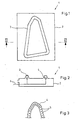
- the Figures 1 and 2 show a heating element 1 with a housing 2, in the upper wall of a heating edge 3 is formed.
- the circumferential contour of the heating edge is adapted to be heated to a paddle surface of a workpiece made of thermoplastic material.
- the heating edge runs in a plane perpendicular to the plane of the drawing. This is just one of the possible configurations. Practice will often require that the heating edge follow a space curve.
- a burner tube 4 which, as FIG. 3 shows, a plurality of nozzle openings 5, the nozzle openings 5 are directed upward so that the flames impinge directly on the back of the heating edge.
- the burner tube 4 follows the course of the heating edge 3, wherein the nozzle openings 5 are distributed over the entire length of the burner tube 4. In the present case 1000 nozzle openings 5 per meter burner tube 4 are provided.
- the arrangement according to the invention allows a very uniform heating of the heating edge 3, in the present case to a temperature of 420 ° C.
- the upper wall of the housing 2 made of stainless steel, preferably made of stainless steel.
- Stainless steel sheet has the additional advantage that plasticized remains of the thermoplastic material do not adhere.
- the burner tube 4 is operated as a premix burner and is connected via a line 6 to a premixing device, not shown.
- a suction device not shown, is provided which supplies the resulting gases during the joining gases and vapors of combustion.
- the gas burner device consist of individual, adjoining and separately fired segments, provided that they heat the heating edge gapless.
- the gas burner device may operate as a mouth mixer.
- the nozzle openings of the embodiment form a single row.
Landscapes
- Engineering & Computer Science (AREA)
- Mechanical Engineering (AREA)
- Physics & Mathematics (AREA)
- Chemical & Material Sciences (AREA)
- Combustion & Propulsion (AREA)
- Thermal Sciences (AREA)
- General Engineering & Computer Science (AREA)
- Lining Or Joining Of Plastics Or The Like (AREA)
- Gas Burners (AREA)
- Resistance Heating (AREA)
- Light Receiving Elements (AREA)
- Apparatuses And Processes For Manufacturing Resistors (AREA)
- Heating, Cooling, Or Curing Plastics Or The Like In General (AREA)
- Mounting, Exchange, And Manufacturing Of Dies (AREA)
Description
- Die Erfindung betrifft ein Heizelement für eine Thermoschweißvorrichtung zum Erwärmen einer Fügefläche eines Werkstücks aus thermoplastischem Material, mit einer beheizbaren Aufheizkante, die an die Kontur der zu erwärmenden Fügefläche des Werkstücks angepaßt ist und mit einer Gasbrennereinrichtung, die auf der Rückseite der Aufheizkante angeordnet ist und deren Kontur folgt.
- Aus der
DE 11 15 006 B ist eine Schweißzange zum Verschweißen von Kunststoffrohren mit zwei halbkreisförmigen Schenkeln, die hohl ausgebildet sind. An jedem Schenkel ist ein Zuleitungsrohr für ein Brenngas oder ein Brenngasgemisch angeordnet. Eine einzige Flamme bildet sich jeweils an der Stelle aus, an der das Zuleitungsrohr in die Schenkel mündet. - Die
US-A-3455 761 zeigt ebenfalls eine beheizte Schweißzange, bei der eine einzige Flamme in einem ringförmigen Hohlraum erzeugt wird. - Die
CH 334 038 A - Bei allen drei gekannten Vorrichtungen besteht die Gefahr, dass die Erwärmung der Aufheizkanten unregelmäßig erfolgt.
- In der Thermoschweißvorrichtung werden die Fügeflächen der miteinander zu verbindenden Werkstücke so weit erwärmt, daß sich anschließend beim Zusammenfügen und Zusammenpressen der Werkstücke die gewünschte Schweißverbindung ergibt.
- Die hierzu aus der Praxis bekannten Heizelemente bestehen aus Aluminiumblöcken, die von elektrischen Heizpatronen beheizt werden. Zwar besitzt Aluminium eine sehr gute Wärmeleitfähigkeit, jedoch wurde gefunden, daß die Gleichmäßigkeit der Erwärmung entlang der Aufheizkante zu Wünschen übrig läßt. Auch ist die maximale Temperatur auf ca. 250°C begrenzt.
- Der Erfindung liegt die Aufgabe zugrunde, hier Abhilfe zu schaffen und ein Heizelement vorzuschlagen, das eine sehr gleichmäßige Erwärmung der Aufheizkante unter Erzielung höherer Temperaturen gewährleistet.
- Zur Lösung dieser Aufgabe ist das eingangs genannte Heizelement erfindungsgemäß dadurch gekennzeichnet, dass die Gasbrennereinrichtung als Brennerrohr ausgebildet ist, das eine Mehrzahl von Düsenöffnungen aufweist, die sich über die Länge der Aufheizkante erstrecken und dass die Flammen der Gasbrennereinrichtung gegen die Rückseite der Aufheizkante (3) gerichtet sind.
- Die Gasbrennereinrichtung ist in der Lage, eine sehr gleichmäßige Erwärmung der Aufheizkante zu bewirken. Auch ist die Beheizung direkt und dementsprechend sehr intensiv. So besteht ohne weiteres die Möglichkeit, die Aufheizkante auf Temperaturen zu bringen, die 450°C und mehr betragen. Das Heizelement arbeitet mit hohem Wirkungsgrad.
- Für das Heizelement kommen grundsätzlich sämtliche Materialien in Frage, die eine ausreichende Temperaturbeständigkeit besitzen. Zu denken ist beispielsweise an keramische Materialien, die außerdem den Vorteil aufweisen, daß auch komplizierte Konturen der Aufheizkante fertigungstechnisch ohne weiteres beherrschbar sind. Letzteres gilt auch für Edelstahlblech, und es wird daher vorgeschlagen, daß das Heizelement mindesten im Bereich der Aufheizkante aus Edelstahl besteht. Die Verwendung von Edelstahl bringt noch einen weiteren Vorteil mit sich, dessen Bedeutung nicht zu unterschätzen ist. Das plastifizierte thermoplastische Material neigt dazu, an Aluminium zu haften. Diese Neigung ist bei Edelstahl nicht vorhanden. Anhaftende Materialreste beeinträchtigen die Qualität der aktuellen Fügeverbindung und auch der nachfolgenden Fügeverbindung. Außerdem erhöht sich die Umweltbelastung durch die zusätzliche Freisetzung von Gasen und Dämpfen.
- Wie bereits erwähnt, ist die Beheizung durch die Gasbrennereinrichtung sehr intensiv. Dadurch wird eine etwaige geringe Wärmeleitfähigkeit des Materials der Aufheizkante mehr als kompensiert. Dies gilt beispielsweise für Edelstahl.
- Das Heizelement nach der Erfindung ist wesentlich leichter als ein Aluminiumblock. Es sind also geringere Massen zu bewegen.
- Auch ergeben sich schnellere Aufheiz- und Abkühlraten. Schließlich kann eine längere Lebensdauer erzielt werden.
- Bei alledem sind die erfindungsgemäßen Maßnahmen äußerst einfach und kostengünstig.
- Ferner hat es sich als vorteilhaft erwiesen, die Gasbrennereinrichtung als Vormischbrennereinrichtung zu betreiben. Die Gasbrennereinrichtung kann dabei in einem Gehäuse angeordnet sein, welches die Aufheizkante bildet.
- In wesentlicher Weiterbildung der Erfindung wird vorgeschlagen, daß die Gasbrennereinrichtung mit einer Absaugeinrichtung gekoppelt ist, die die beim Fügen entstehenden Gase und Dämpfe der Verbrennung zuführt. Die Nachverbrennung der Gase und Dämpfe führt zu deren problemloser Entsorgung, wozu eine elektrische Beheizung nicht in der Lage ist.
- Überraschenderweise wurde gefunden, daß der Verlauf der Kontur der Aufheizkante Einfluß auf den örtlichen Wärmebedarf hat, ein Umstand, dem mit einer elektrischen Beheizung nicht Rechnung getragen werden kann. In Weiterbildung der Erfindung hingegen ist dies möglich, und zwar dadurch, daß die Heizleistung der Gasbrennereinrichtung an den Verlauf der Kontur der Aufheizkante angepaßt ist. Dies trägt dazu bei, eine gleichmäßige Temperatur der Fügefläche zu erzielen, und zwar insbesondere dann, wenn die Aufheizkante in den Bereichen der Umlenkstellen ihrer Kontur intensiver beheizbar ist als in den Bereichen geradlinigen Verlaufs.
- Die Gestaltung der Gasbrennereinrichtung als Brennerrohr zeichnet sich durch eine besonders einfache und robuste Konstruktion aus.
- Dabei können die Düsenöffnungen in einer Reihe angeordnet sein, und zwar 800 bis 1000 Düsen/m.
- Um die gewünschte Leistungsanpassung zu erzielen, sind die Abstände zwischen den Düsenöffnungen über der Länge des Brennerrohres vorzugsweise unterschiedlich.
- Die Erfindung wird im folgenden anhand eines bevorzugten Ausführungsbeispiels im Zusammenhang mit der beiliegenden Zeichnung näher erläutert. Die Zeichnung zeigt in:
-
Figur 1 einen Grundriß eines erfindungsgemäßen Heizelements; -
Figur 2 einen Schnitt entlang der Linie II-II inFigur 1 ; -
Figur 3 einen Teil-Grundriß eines Brennerrohrs. - Die
Figuren 1 und 2 zeigen ein Heizelement 1 mit einem Gehäuse 2, in dessen oberer Wand eine Aufheizkante 3 ausgebildet ist. Die umlaufende Kontur der Aufheizkante ist an eine zu erwärmende Fügelfläche eines Werkstücks aus thermoplastischem Material angepaßt. - Im vorliegenden Fall verläuft die Aufheizkante in einer Ebene senkrecht zur Zeichenebene. Dies stellt nur eine der möglichen Konfigurationen dar. Die Praxis wird häufig fordern, daß die Aufheizkante einer Raumkurve folgt.
- Unterhalb der Aufheizkante 3 verläuft ein Brennerrohr 4, das, wie
Figur 3 zeigt, eine Mehrzahl von Düsenöffnungen 5 aufweist die Düsenöffnungen 5 sind nach oben gerichtet, so daß die Flammen direkt auf die Rückseite der Auf heizkante auftreffen. Das Brennerrohr 4 folgt dem Verlauf der Aufheizkante 3, wobei die Düsenöffnungen 5 über die gesamte Länge des Brennerrohres 4 verteilt sind. Im vorliegenden Fall sind 1000 Düsenöffnungen 5 pro Meter Brennerrohr 4 vorgesehen. - Die erfindungsgemäße Anordnung ermöglicht eine sehr gleichmäßige Erwärmung der Aufheizkante 3, und zwar im vorliegenden Fall auf eine Temperatur von 420°C. Hierzu besteht die obere Wand des Gehäuses 2 aus Edelstahl, vorzugsweise aus Edelstahl. Edelstahlblech bringt den zusätzlichen Vorteil mit sich, daß plastifizierte Reste des thermoplastischen Materials nicht haften bleiben.
- Das Brennerrohr 4 wird als Vormischbrenner betrieben und ist über eine Leitung 6 an eine nicht dargestellte Vormischeinrichtung angeschlossen.
- Ferner ist eine nicht dargestellte Absaugeinrichtung vorgesehen, die die beim Fügen entstehenden Gase und Dämpfe der Verbrennung zuführt.
- Im Rahmen der Erfindung sind durchaus Abwandlungsmöglichkeiten gegeben. So kann die Gasbrennereinrichtung aus einzelnen, aneinander anschließenden und getrennt befeuerten Segmenten bestehen, sofern diese die Aufheizkante lückenlos beheizen. Auch kann die Gasbrennereinrichtung als Mündungsmischer arbeiten. Die Düsenöffnungen des Ausführungsbeispiels bilden eine einzige Reihe.
Claims (9)
- Heizelement für eine Thermoschweißvorrichtung zum Erwärmen einer Fügefläche eines Werkstücks aus thermoplastischem Material, mit einer beheizbaren Aufheizkante (3), die an die Kontur der zu erwärmenden Fügefläche des Werkstücks angepaßt ist und mit einer Gasbrennereinrichtung (4), die auf der Rückseite der Aufheizkante (3) angeordnet ist und deren Kontur folgt,
dadurch gekennzeichnet,
dass die Gasbrennereinrichtung (4) als Brennerrohr ausgebildet ist, das eine Mehrzahl von Düsenöffnungen (5) aufweist, die sich über die Länge der Aufheizkante (3) erstrecken und dass die Flammen der Gasbrennereinrichtung (4) gegen die Rückseite der Aufheizkante (3) gerichtet sind. - Heizelement nach Anspruch 1, dadurch gekennzeichnet, daß es mindestens im Bereich der Aufheizkante (3) aus Edelstahl besteht.
- Heizelement nach einem der Ansprüche 1 oder 2, dadurch gekennzeichnet, daß die Gasbrennereinrichtung (4) als Vormischbrennereinrichtung betreibbar ist.
- Heizelement nach Anspruch 3, dadurch gekennzeichnet, daß die Gasbrennereinrichtung (4) in einem Gehäuse (2) angeordnet ist, welches die Aufheizkante (3) bildet.
- Heizelement nach einem der Ansprüche 1 bis 4, dadurch gekennzeichnet, daß die Gasbrennereinrichtung (4) mit einer Absaugeinrichtung gekoppelt ist, die die beim Fügen entstehenden Gase und Dämpfe der Verbrennung zuführt.
- Heizelement nach einem der Ansprüche 1 bis 5, dadurch gekennzeichnet, daß die Heizleistung der Gasbrennereinrichtung (4) an den Verlauf der Kontur der Aufheizkante (3) angepaßt ist.
- Heizelement nach Anspruch 6, dadurch gekennzeichnet, daß die Aufheizkante in den Bereichen der Umlenkstellen ihrer Kontur intensiver beheizbar ist als in den Bereichen geradlinigen Verlaufs.
- Heizelement nach Anspruch einem der Ansprüche 1 bis 7, dadurch gekennzeichnet, daß die Düsenöffnungen (5) in einer Reihe angeordnet sind, und zwar 800 bis 1000 Düsenöffnungen/m.
- Heizelement nach Anspruch 8, dadurch gekennzeichnet, daß die Abstände zwischen den Düsenöffnungen (5) des Brennerrohres (4) über dessen Länge unterschiedlich sind.
Applications Claiming Priority (3)
| Application Number | Priority Date | Filing Date | Title |
|---|---|---|---|
| DE10247840 | 2002-10-14 | ||
| DE2002147840 DE10247840A1 (de) | 2002-10-14 | 2002-10-14 | Heizelement für eine Thermoschweissvorrichtung |
| PCT/EP2003/009422 WO2004035298A1 (de) | 2002-10-14 | 2003-08-26 | Heizelement für eine thermoschweissvorrichtung |
Publications (2)
| Publication Number | Publication Date |
|---|---|
| EP1554107A1 EP1554107A1 (de) | 2005-07-20 |
| EP1554107B1 true EP1554107B1 (de) | 2009-12-09 |
Family
ID=32038651
Family Applications (1)
| Application Number | Title | Priority Date | Filing Date |
|---|---|---|---|
| EP20030808686 Expired - Lifetime EP1554107B1 (de) | 2002-10-14 | 2003-08-26 | Heizelement für eine thermoschweissvorrichtung |
Country Status (5)
| Country | Link |
|---|---|
| EP (1) | EP1554107B1 (de) |
| AT (1) | ATE451219T1 (de) |
| AU (1) | AU2003261654A1 (de) |
| DE (2) | DE10247840A1 (de) |
| WO (1) | WO2004035298A1 (de) |
Families Citing this family (1)
| Publication number | Priority date | Publication date | Assignee | Title |
|---|---|---|---|---|
| DE102007026163A1 (de) * | 2007-06-04 | 2008-12-11 | Bielomatik Leuze Gmbh + Co Kg | Verfahren und Vorrichtung zum Aufschmelzen eines thermoplastischen Kunststoffes, insbesondere zum Schweißen von Kunststoffteilen |
Family Cites Families (10)
| Publication number | Priority date | Publication date | Assignee | Title |
|---|---|---|---|---|
| CH334038A (de) | 1955-08-23 | 1958-11-15 | Fischer Ag Georg | Vorrichtung zum Verschweissen von Rohren und Verbindungsteilen aus Kunststoff |
| FR1219314A (fr) * | 1958-12-23 | 1960-05-17 | Carnaud & Forges | Procédé et dispositif d'assemblage et de soudage de boîtes de conserves |
| DE1115006B (de) | 1960-02-17 | 1961-10-12 | Draegerwerk Ag | Schweisszange fuer das Bearbeiten von Rohren, Kabelmuffen od. dgl. aus thermoplastischem Werkstoff |
| US3457339A (en) * | 1965-12-08 | 1969-07-22 | Pall Corp | Process for making end capped filter elements |
| US3455761A (en) | 1966-02-18 | 1969-07-15 | Cabot Corp | Polymeric welding process and apparatus |
| DE2104070A1 (en) * | 1971-01-28 | 1972-08-17 | Kerner F | Welding laminated plastic sheet - without direct flame contact |
| ATA515380A (de) * | 1980-10-17 | 1982-04-15 | Richard Tscherwitschke Ges Mit | Schweissvorrichtung zum verbinden von insbesondere senkrecht zueinander angeordneten werkstuecken aus thermoplastischem kunststoff |
| DE3539842A1 (de) * | 1985-11-09 | 1987-05-14 | Wegener Gmbh & Co Kg | Schweisseinrichtung |
| DE10019163A1 (de) * | 2000-04-12 | 2001-10-18 | Volkswagen Ag | Ausströmvorrichtung zum Warmgas-Verschweißen von Kunststoffteilen und Verfahren zum Warmgas-Verschweißen von Kunststoffteilen |
| DE10028669A1 (de) * | 2000-06-09 | 2001-12-13 | Ruhrgas Ag | Verfahren und Vorrichtung zum Erwärmen von flächigem Material |
-
2002
- 2002-10-14 DE DE2002147840 patent/DE10247840A1/de not_active Withdrawn
-
2003
- 2003-08-26 DE DE50312212T patent/DE50312212D1/de not_active Expired - Lifetime
- 2003-08-26 AT AT03808686T patent/ATE451219T1/de not_active IP Right Cessation
- 2003-08-26 EP EP20030808686 patent/EP1554107B1/de not_active Expired - Lifetime
- 2003-08-26 AU AU2003261654A patent/AU2003261654A1/en not_active Abandoned
- 2003-08-26 WO PCT/EP2003/009422 patent/WO2004035298A1/de not_active Ceased
Also Published As
| Publication number | Publication date |
|---|---|
| WO2004035298A1 (de) | 2004-04-29 |
| EP1554107A1 (de) | 2005-07-20 |
| DE10247840A1 (de) | 2004-04-22 |
| ATE451219T1 (de) | 2009-12-15 |
| DE50312212D1 (de) | 2010-01-21 |
| AU2003261654A1 (en) | 2004-05-04 |
Similar Documents
| Publication | Publication Date | Title |
|---|---|---|
| DE102012213796B4 (de) | Verfahren und Vorrichtung zum Beschichten von Werkstücken | |
| DE3433013C2 (de) | Kochextruder | |
| DE10250751A1 (de) | Verfahren zum Schweissen von Kunststoffteilen, insbesondere zum Verbinden von Kunststoffteilen entlang einer Schweisslinie | |
| DE3614339A1 (de) | Waermetauscher und verfahren zum herstellen von waermetauschern | |
| EP3676079A1 (de) | KONTAKTSCHWEIßHEIZKOMPONENTE UND SCHWEIßAUTOMAT | |
| DE102020125290B4 (de) | Verfahren und Vorrichtung zum Schweißen von Kunststoffteilen | |
| EP1554107B1 (de) | Heizelement für eine thermoschweissvorrichtung | |
| EP2878430B1 (de) | Kunststoffrohr-Stumpfschweißmaschine, Heizelement hierfür sowie Verfahren zur Herstellung eines Plattenheizkörpers | |
| EP0037046B1 (de) | Strahlungsbrenner | |
| DE10352821B4 (de) | Vorrichtung zum Heißluftnieten | |
| DE10342921B4 (de) | Verfahren zum Verschweißen von Kunststoffen und einem hierzu notwendigen Schweißmittel | |
| AT506724B1 (de) | Verfahren zum schweissen von teilen aus thermoplastischen materialien | |
| DE8106837U1 (de) | Gasbrenner zum erzeugen von infrarotstrahlen | |
| EP0587689B1 (de) | Mehrfach gefaltete einrohrglasgefässe sowie vorrichtung und verfahren zu deren herstellung | |
| EP0967435B1 (de) | Zündbrenner | |
| DE102016111305B4 (de) | Verfahren und Vorrichtung zum Aufschweißen einer Schicht aus einem Kunststoffmaterial auf ein Kunststoffrohr | |
| DE2553553C2 (de) | Vorrichtung zum Flammen eines Werkstuckes | |
| EP1653153B1 (de) | Flammrohr für einen Brenner zur Heissgaserzeugung sowie Verfahren zum Herstellen eines solchen Flammrohrs | |
| DE3904838A1 (de) | Rohrverbindung, insbesondere fuer kunststoffrohre und -schlaeuche oder dergleichen sowie verfahren und vorrichtung zu ihrer herstellung | |
| DE20218928U1 (de) | Heizelement für das Heizelementstumpfschweißen von Kunststoffwerkstücken | |
| DE3325339A1 (de) | Verfahren und vorrichtung zum verschweissen der raender von kunststoffbahnen | |
| DE1002123B (de) | Verfahren zur Herstellung nahtloser Verbindungen an Gegenstaenden aus thermoplastischem Werkstoff, insbesondere Polyacrylharz | |
| DE808264C (de) | Gasbeheizter Feueranzuender fuer schwer entflammbare Brennstoffe | |
| DE2739102A1 (de) | Brenner | |
| DE102010014721A1 (de) | Laser-Schweißpistole sowie Verfahren zur Herstellung einer Schweißverbindung |
Legal Events
| Date | Code | Title | Description |
|---|---|---|---|
| PUAI | Public reference made under article 153(3) epc to a published international application that has entered the european phase |
Free format text: ORIGINAL CODE: 0009012 |
|
| 17P | Request for examination filed |
Effective date: 20050319 |
|
| AK | Designated contracting states |
Kind code of ref document: A1 Designated state(s): AT BE BG CH CY CZ DE DK EE ES FI FR GB GR HU IE IT LI LU MC NL PT RO SE SI SK TR |
|
| AX | Request for extension of the european patent |
Extension state: AL LT LV MK |
|
| RAP1 | Party data changed (applicant data changed or rights of an application transferred) |
Owner name: E.ON RUHRGAS AG |
|
| DAX | Request for extension of the european patent (deleted) | ||
| 17Q | First examination report despatched |
Effective date: 20070605 |
|
| GRAP | Despatch of communication of intention to grant a patent |
Free format text: ORIGINAL CODE: EPIDOSNIGR1 |
|
| GRAS | Grant fee paid |
Free format text: ORIGINAL CODE: EPIDOSNIGR3 |
|
| GRAA | (expected) grant |
Free format text: ORIGINAL CODE: 0009210 |
|
| AK | Designated contracting states |
Kind code of ref document: B1 Designated state(s): AT BE BG CH CY CZ DE DK EE ES FI FR GB GR HU IE IT LI LU MC NL PT RO SE SI SK TR |
|
| REG | Reference to a national code |
Ref country code: GB Ref legal event code: FG4D Free format text: NOT ENGLISH |
|
| REG | Reference to a national code |
Ref country code: CH Ref legal event code: EP |
|
| REG | Reference to a national code |
Ref country code: IE Ref legal event code: FG4D |
|
| REF | Corresponds to: |
Ref document number: 50312212 Country of ref document: DE Date of ref document: 20100121 Kind code of ref document: P |
|
| REG | Reference to a national code |
Ref country code: NL Ref legal event code: VDEP Effective date: 20091209 |
|
| PG25 | Lapsed in a contracting state [announced via postgrant information from national office to epo] |
Ref country code: SE Free format text: LAPSE BECAUSE OF FAILURE TO SUBMIT A TRANSLATION OF THE DESCRIPTION OR TO PAY THE FEE WITHIN THE PRESCRIBED TIME-LIMIT Effective date: 20091209 Ref country code: FI Free format text: LAPSE BECAUSE OF FAILURE TO SUBMIT A TRANSLATION OF THE DESCRIPTION OR TO PAY THE FEE WITHIN THE PRESCRIBED TIME-LIMIT Effective date: 20091209 |
|
| PG25 | Lapsed in a contracting state [announced via postgrant information from national office to epo] |
Ref country code: SI Free format text: LAPSE BECAUSE OF FAILURE TO SUBMIT A TRANSLATION OF THE DESCRIPTION OR TO PAY THE FEE WITHIN THE PRESCRIBED TIME-LIMIT Effective date: 20091209 |
|
| REG | Reference to a national code |
Ref country code: IE Ref legal event code: FD4D |
|
| PG25 | Lapsed in a contracting state [announced via postgrant information from national office to epo] |
Ref country code: RO Free format text: LAPSE BECAUSE OF FAILURE TO SUBMIT A TRANSLATION OF THE DESCRIPTION OR TO PAY THE FEE WITHIN THE PRESCRIBED TIME-LIMIT Effective date: 20091209 Ref country code: NL Free format text: LAPSE BECAUSE OF FAILURE TO SUBMIT A TRANSLATION OF THE DESCRIPTION OR TO PAY THE FEE WITHIN THE PRESCRIBED TIME-LIMIT Effective date: 20091209 Ref country code: IE Free format text: LAPSE BECAUSE OF FAILURE TO SUBMIT A TRANSLATION OF THE DESCRIPTION OR TO PAY THE FEE WITHIN THE PRESCRIBED TIME-LIMIT Effective date: 20091209 Ref country code: ES Free format text: LAPSE BECAUSE OF FAILURE TO SUBMIT A TRANSLATION OF THE DESCRIPTION OR TO PAY THE FEE WITHIN THE PRESCRIBED TIME-LIMIT Effective date: 20100320 Ref country code: EE Free format text: LAPSE BECAUSE OF FAILURE TO SUBMIT A TRANSLATION OF THE DESCRIPTION OR TO PAY THE FEE WITHIN THE PRESCRIBED TIME-LIMIT Effective date: 20091209 Ref country code: BG Free format text: LAPSE BECAUSE OF FAILURE TO SUBMIT A TRANSLATION OF THE DESCRIPTION OR TO PAY THE FEE WITHIN THE PRESCRIBED TIME-LIMIT Effective date: 20100309 Ref country code: PT Free format text: LAPSE BECAUSE OF FAILURE TO SUBMIT A TRANSLATION OF THE DESCRIPTION OR TO PAY THE FEE WITHIN THE PRESCRIBED TIME-LIMIT Effective date: 20100409 |
|
| PG25 | Lapsed in a contracting state [announced via postgrant information from national office to epo] |
Ref country code: SK Free format text: LAPSE BECAUSE OF FAILURE TO SUBMIT A TRANSLATION OF THE DESCRIPTION OR TO PAY THE FEE WITHIN THE PRESCRIBED TIME-LIMIT Effective date: 20091209 Ref country code: CZ Free format text: LAPSE BECAUSE OF FAILURE TO SUBMIT A TRANSLATION OF THE DESCRIPTION OR TO PAY THE FEE WITHIN THE PRESCRIBED TIME-LIMIT Effective date: 20091209 |
|
| PLBE | No opposition filed within time limit |
Free format text: ORIGINAL CODE: 0009261 |
|
| STAA | Information on the status of an ep patent application or granted ep patent |
Free format text: STATUS: NO OPPOSITION FILED WITHIN TIME LIMIT |
|
| PG25 | Lapsed in a contracting state [announced via postgrant information from national office to epo] |
Ref country code: CY Free format text: LAPSE BECAUSE OF FAILURE TO SUBMIT A TRANSLATION OF THE DESCRIPTION OR TO PAY THE FEE WITHIN THE PRESCRIBED TIME-LIMIT Effective date: 20091209 Ref country code: GR Free format text: LAPSE BECAUSE OF FAILURE TO SUBMIT A TRANSLATION OF THE DESCRIPTION OR TO PAY THE FEE WITHIN THE PRESCRIBED TIME-LIMIT Effective date: 20100310 |
|
| 26N | No opposition filed |
Effective date: 20100910 |
|
| PG25 | Lapsed in a contracting state [announced via postgrant information from national office to epo] |
Ref country code: DK Free format text: LAPSE BECAUSE OF FAILURE TO SUBMIT A TRANSLATION OF THE DESCRIPTION OR TO PAY THE FEE WITHIN THE PRESCRIBED TIME-LIMIT Effective date: 20091209 |
|
| BERE | Be: lapsed |
Owner name: E.ON RUHRGAS A.G. Effective date: 20100831 |
|
| PG25 | Lapsed in a contracting state [announced via postgrant information from national office to epo] |
Ref country code: MC Free format text: LAPSE BECAUSE OF NON-PAYMENT OF DUE FEES Effective date: 20100831 Ref country code: IT Free format text: LAPSE BECAUSE OF FAILURE TO SUBMIT A TRANSLATION OF THE DESCRIPTION OR TO PAY THE FEE WITHIN THE PRESCRIBED TIME-LIMIT Effective date: 20091209 |
|
| REG | Reference to a national code |
Ref country code: CH Ref legal event code: PL |
|
| GBPC | Gb: european patent ceased through non-payment of renewal fee |
Effective date: 20100826 |
|
| PG25 | Lapsed in a contracting state [announced via postgrant information from national office to epo] |
Ref country code: LI Free format text: LAPSE BECAUSE OF NON-PAYMENT OF DUE FEES Effective date: 20100831 Ref country code: CH Free format text: LAPSE BECAUSE OF NON-PAYMENT OF DUE FEES Effective date: 20100831 |
|
| REG | Reference to a national code |
Ref country code: FR Ref legal event code: ST Effective date: 20110502 |
|
| PG25 | Lapsed in a contracting state [announced via postgrant information from national office to epo] |
Ref country code: FR Free format text: LAPSE BECAUSE OF NON-PAYMENT OF DUE FEES Effective date: 20100831 Ref country code: BE Free format text: LAPSE BECAUSE OF NON-PAYMENT OF DUE FEES Effective date: 20100831 |
|
| PG25 | Lapsed in a contracting state [announced via postgrant information from national office to epo] |
Ref country code: GB Free format text: LAPSE BECAUSE OF NON-PAYMENT OF DUE FEES Effective date: 20100826 |
|
| PG25 | Lapsed in a contracting state [announced via postgrant information from national office to epo] |
Ref country code: AT Free format text: LAPSE BECAUSE OF NON-PAYMENT OF DUE FEES Effective date: 20100826 |
|
| PG25 | Lapsed in a contracting state [announced via postgrant information from national office to epo] |
Ref country code: HU Free format text: LAPSE BECAUSE OF FAILURE TO SUBMIT A TRANSLATION OF THE DESCRIPTION OR TO PAY THE FEE WITHIN THE PRESCRIBED TIME-LIMIT Effective date: 20100610 Ref country code: LU Free format text: LAPSE BECAUSE OF NON-PAYMENT OF DUE FEES Effective date: 20100826 |
|
| PG25 | Lapsed in a contracting state [announced via postgrant information from national office to epo] |
Ref country code: TR Free format text: LAPSE BECAUSE OF FAILURE TO SUBMIT A TRANSLATION OF THE DESCRIPTION OR TO PAY THE FEE WITHIN THE PRESCRIBED TIME-LIMIT Effective date: 20091209 |
|
| REG | Reference to a national code |
Ref country code: DE Ref legal event code: R081 Ref document number: 50312212 Country of ref document: DE Owner name: E.ON NEW BUILD & TECHNOLOGY GMBH, DE Free format text: FORMER OWNER: E.ON RUHRGAS AG, 45131 ESSEN, DE Effective date: 20130204 |
|
| PGFP | Annual fee paid to national office [announced via postgrant information from national office to epo] |
Ref country code: DE Payment date: 20130821 Year of fee payment: 11 |
|
| REG | Reference to a national code |
Ref country code: DE Ref legal event code: R119 Ref document number: 50312212 Country of ref document: DE |
|
| REG | Reference to a national code |
Ref country code: DE Ref legal event code: R119 Ref document number: 50312212 Country of ref document: DE Effective date: 20150303 |
|
| PG25 | Lapsed in a contracting state [announced via postgrant information from national office to epo] |
Ref country code: DE Free format text: LAPSE BECAUSE OF NON-PAYMENT OF DUE FEES Effective date: 20150303 |