EP1553351B1 - Haushaltsgerät, insbesondere Gargerät - Google Patents
Haushaltsgerät, insbesondere Gargerät Download PDFInfo
- Publication number
- EP1553351B1 EP1553351B1 EP20050100113 EP05100113A EP1553351B1 EP 1553351 B1 EP1553351 B1 EP 1553351B1 EP 20050100113 EP20050100113 EP 20050100113 EP 05100113 A EP05100113 A EP 05100113A EP 1553351 B1 EP1553351 B1 EP 1553351B1
- Authority
- EP
- European Patent Office
- Prior art keywords
- muffle
- wall
- cooking appliance
- appliance according
- wall element
- Prior art date
- Legal status (The legal status is an assumption and is not a legal conclusion. Google has not performed a legal analysis and makes no representation as to the accuracy of the status listed.)
- Expired - Lifetime
Links
- 238000010411 cooking Methods 0.000 title claims description 43
- 238000009434 installation Methods 0.000 claims description 9
- 238000010438 heat treatment Methods 0.000 claims 1
- 238000003780 insertion Methods 0.000 description 24
- 230000037431 insertion Effects 0.000 description 24
- 229910000831 Steel Inorganic materials 0.000 description 9
- 239000010959 steel Substances 0.000 description 9
- 230000013011 mating Effects 0.000 description 5
- 210000003298 dental enamel Anatomy 0.000 description 3
- 238000005516 engineering process Methods 0.000 description 3
- 238000004519 manufacturing process Methods 0.000 description 3
- 239000000463 material Substances 0.000 description 3
- 239000011343 solid material Substances 0.000 description 3
- 230000004048 modification Effects 0.000 description 2
- 238000012986 modification Methods 0.000 description 2
- 230000008646 thermal stress Effects 0.000 description 2
- 238000005452 bending Methods 0.000 description 1
- 238000004049 embossing Methods 0.000 description 1
- 238000000605 extraction Methods 0.000 description 1
- 230000002349 favourable effect Effects 0.000 description 1
- 230000017525 heat dissipation Effects 0.000 description 1
- 239000011796 hollow space material Substances 0.000 description 1
- 239000002184 metal Substances 0.000 description 1
- 230000035882 stress Effects 0.000 description 1
- 230000007704 transition Effects 0.000 description 1
- 238000011144 upstream manufacturing Methods 0.000 description 1
Images



Classifications
-
- F—MECHANICAL ENGINEERING; LIGHTING; HEATING; WEAPONS; BLASTING
- F24—HEATING; RANGES; VENTILATING
- F24C—DOMESTIC STOVES OR RANGES ; DETAILS OF DOMESTIC STOVES OR RANGES, OF GENERAL APPLICATION
- F24C15/00—Details
- F24C15/16—Shelves, racks or trays inside ovens; Supports therefor
Definitions
- the invention relates to a cooking appliance with a device muffle, in which at least one accessory part is supported on at least one muffle wall, which has a bearing pin, which is guided for mounting the accessory by a mounting opening.
- US 2,944,139 is a generic cooking appliance with a device muffle known. On the side walls of the muffle rods are supported in the horizontal direction. These bars carry racks for Gargut proceedingsnisse, such as a baking sheet. The rods are each mounted in mounting holes of the muffle side wall and the muffle back wall.
- the object of the invention is to provide a household appliance, in particular cooking appliance, with a device muffle, in which a cooking operation is thermally favorable feasible.
- a cooking appliance with the features of claim 1.
- a wall element is provided in which the mounting hole is formed for the bearing pin.
- the wall element has a mounting flange spaced from the muffle wall.
- the at least one mounting opening for the bearing pin of the accessory can be arranged. Since according to the invention the mounting opening is not formed in the muffle wall, the muffle side wall remains closed to the outside. During the cooking operation, therefore, a heat loss from the oven is reduced. Furthermore, due to the distance between the mounting flange and the muffle wall, sufficient space remains behind the wall element in order to mount approximately a bearing bush in the mounting opening.
- the garrauminnen wall element a number of mounting holes for bearing pin several accessories is formed.
- a number of mounting holes for a plurality of accessories can be formed.
- the wall element as an angled profile part is trained. This ensures a sufficient rigidity of the wall element when subjected to thermal stress.
- the wall element can have at least one abutment flange. This can be flat with the side wall in Appendix. In this way, the wall element can be held with its abutment flange dimensionally stable on the side wall.
- the bearing pin can be stored in the manner of a floating bearing with a longitudinal clearance in the mounting hole of the mounting flange.
- a collar that moves the mounting opening projects like a cup into the cooking chamber.
- This cup-shaped collar simplifies the insertion of the bearing pin in the mounting hole.
- it serves as a butt edge during the insertion of the bearing pin of the accessory.
- the wall element may be associated with a screen, which covers the wall element relative to the cooking chamber.
- the surface of the diaphragm can be formed corresponding to the surface of the muffle walls. In this way, the aperture appears optically in the background together with the wall element.
- the surface of the diaphragm may be enamelled accordingly.
- the wall element is designed as a steel sheet with a low material thickness. As a result, an excessively high material input into the device muffle can be avoided in a thermally advantageous manner.
- the diaphragm may have at least one aperture. It is particularly preferred if the cup-shaped collar of the mounting opening protrudes through the aperture into the cooking chamber.
- the cup-shaped collar acting as an insertion aid can thus reduce disadvantageous impacts on the possibly elaborately machined surface of the panel.
- the panel In order to avoid damage to the surface of the muffle wall when installing the wall element or the panel in the device muffle, the panel is slightly spaced from the muffle wall in the mounted state. The aperture is therefore arranged without contact with respect to the muffle wall.
- the muffle wall can be executed at least double-walled together with the garrauminnen practicalen wall element.
- the garrauminnen workede wall element is formed as an air guide plate.
- the air guide plate separates a radiator and / or a fan from the cooking chamber.
- the already existing in the oven air guide plate can serve as a support for the accessory at the same time.
- the air guide plate is arranged between the garraumayne paragraphen wall element and the muffle wall.
- the wall element can be connected directly to the air guide plate. Thermally disadvantageous mounting holes for the wall element can be prevented in the muffle wall.
- FIG. 1 is a cooking appliance with an inside provided with an enamel layer Garausmuffel 1 shown.
- the cooking appliance has a hinged door 3 for closing a front-side muffle opening 5.
- the hinged door 3 is in the closed state in contact with the muffle opening 5 moving front flange 7.
- On the opposite side walls 9 of the cooking appliance muffle 1 corresponding lateral guide elements 11 and a later-described extraction system, consisting of two telescopic extensions 59 are supported.
- the telescopic extensions 59 are supported in a topmost of four horizontal Garraumebenen.
- each side guide elements 11 are supported.
- a baking sheet 13 is supported, which is partially pushed out of the cooking appliance muffle 1.
- Each of the guide elements 11 is formed as a rod-shaped steel profile part or manufacturing part, which has a circular cross-section and consists of a solid material.
- the guide elements 11 and / or the telescopic extensions 59 can be arranged by a user in any manner in the Garellomuffel 1.
- the guide elements 11 and telescopic extensions 59 are mufflefront detergent each mounted in a bearing bush 15.
- the guide elements 11 are each mounted in a mounting opening 19 of a wall element 21. Both the guide elements 11 and the telescopic extensions 59 are tool-free by the user from the muffle 1 to solve.
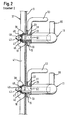
- the muffle front side mounting of the guide elements 11 in the bearing bushes 15 is in the FIG. 2 shown in detail. Consequently, the in the FIG. 3 illustrated as a single part bushing 15 hollow cylindrical with an outer edge flange 23 is formed. This is supported inside a cooking chamber of the muffle 1 inside of the muffle side wall 9.
- the muffle side wall 9 consists of a thin steel sheet with a wall thickness in the range between 0.3 to 0.7 mm.
- the edge flange 23 of the bearing bush 15 goes on garraumayne town mon in an insertion cylinder 25.
- the insertion cylinder 25 serves as an insertion aid for a bearing pin 27, which is formed on a rod end of the rod-shaped guide element 11.
- a hexagon socket provided in order to mount with a corresponding tool, the bearing bush 15 in an opening 10 of the muffle side wall 9 can.
- a the cooking chamber 25 facing insertion opening of the bearing bush 15 is moved from the front side of a front flange 31.
- the front flange 31 of the bearing bush 15 is axially spaced from the edge flange 23.
- an annular groove 33 is formed. This serves, as will be described later, as a mounting portion for suspending the telescopic extensions 59.
- the bearing bush 15 is provided on the outer circumference with an external thread 35 through which the bearing bush according to the FIG. 2 is screwed into the muffle side wall 9.
- a corresponding mating thread 39 is not formed in the thin-walled muffle side wall 9 itself. Rather, the mating thread 39 is formed in a securing element 37.
- the fuse element 37 is according to the FIG. 2 on the outside with the muffle side wall 9 in Appendix. It is designed as an elongate profile part with the corresponding mating threads 39 for the bearing bushes 15.
- the profile part 17 is a cross-sectionally U-shaped steel sheet, whereby it remains torsionally rigid and dimensionally stable even under thermal stress.
- each of the mating thread 39 is incorporated in the manner of a metal nut in the profile part 37.
- the profile part 37 extends in a vertical direction over all in the FIG. 1 Due to the large-scale investment of the profile part 37 on the outside of the side wall 9, the bushings 15 are stably fixed against tilting moments, in spite of the thin-walled muffle side wall 9. Approximately midway between the two legs of the U-shaped security element 37th the mating threads 39 are formed.
- the bearing bush 15 is guided with its external thread 35 with a clearance through the opening 10 of the muffle side wall 9.
- the bearing bush 15 is therefore not bolted directly to the muffle side wall 9. Rather, the muffle side wall 9 is clamped between the securing element 37 and the edge flange 23 of the bearing bush 15.
- the bearing pin 27 of the guide member 11 between two spring legs of the wire spring 45 securely locked.
- the bearing pin 27 of the guide member 11 at its insertion end a locking groove 47, in which the two spring legs of the wire spring 45 are engaged.
- the bearing pin 27 is formed with an insertion cone 49, which serves as an insertion aid for the bearing pin 27.
- a transition section 46 between the insertion cone 49 and the locking groove 47 expands in the direction of the insertion cone 49 in a conical manner.
- the bearing pin 27 of the guide member 11 is reduced to a diameter which allows a positive storage in the bearing bush 15. As a result, a play-free mounting of the guide member 11 is achieved in the bearing bush 15. This is further supported by a contact shoulder 51 of the bearing pin 27, which is in contact with the front flange 31 of the bearing bush 15.
- the bearing bush 15 is shown in a modification. Unlike the one in the FIG. 3 shown bearing bush is in the bearing bush of the FIG. 4 dispensed with the front flange 31.
- the bearing bush 15 therefore has garrauminnen colour only the edge flange 23.
- the abutment shoulder 51 is pressed in a corresponding manner against the edge flange 23 of the bearing pin 27.
- the garraumau wente end of the in the FIG. 4 shown bearing bush 15 closed.
- a securing nut is provided instead of a single profile part for all bearing bushes 15. This is in the FIG. 4 screwed onto the external thread 35 of the bearing bush 15.
- 15 is in the region of the closed end of the bearing bush in the Outside a slot 52 is provided. In the slot 52, a spring leg of the wire spring 45 is inserted, which engages in the locking groove 47 of the bearing pin 27.
- FIG. 5 a taken out of the Garausmuffel 1 guide element 11 is shown.
- the bearing pin 27 is formed on a rod end of the guide member 11 with a reduced diameter. Since the guide element 11 consists of a solid material, manufacturing technology can be easily formed, for example by means of a lathe of the bearing pin 27 at the rod end.
- the provided with the bearing pin 27 rod end of the guide member 11 is also bent angularly. A bending necessary for this purpose is compared to a hollow material in the solid material used here, manufacturing technology easily feasible.
- the guide elements 11 and telescopic extensions 59 are each independently formed and inserted into the muffle 1, as is apparent from the FIG. 1 is apparent. Accordingly, they can be taken independently of each other from the oven, unless they are needed to hold a food support. As a result, a material entry into the cooking appliance muffle 1 can be kept as low as possible in terms of heat technology.
- the L-shaped guide element 11 is formed with a leg along the muffle side wall 9 elongated leg, which serves for guiding and supporting of insertion parts.
- the L-shape of the guide element 11 makes it possible to support the guide element 11 with its muffle back-side bar end 54 on the muffle rear wall 17 and with the bent muffle front side bar end on the muffle side wall 9. By this holder on two different muffle walls, the guide member 11 is more resistant to tilting moments.
- Muffle front side is provided on the guide member 11, a height stop 53 as a tilt protection for insertion parts. This is pressed as a bent steel wire bracket with its two ends in corresponding holes of the guide member 11. Accordingly, a further bore in the guide element 11 is formed in the region of the muffle backside rod end 54 offset by 90 °. In this a steel pin is pressed, which serves as a slot stop 55 for an insertion part.
- FIG. 6 an alternative use of the bearing bush 15 is shown.
- no rod-shaped guide element 11 is inserted into the bearing bush 15.
- a retaining plate 57 of the in the FIG. 1 shown telescopic extension 59 mounted in the annular groove 33 of the bearing bush 15.
- the telescopic extension 59 has according to the FIG. 1 a rear pin 61 for mounting on the muffle back wall 17.
- the pin 61 is formed like the rear rod end 54 of the guide elements 11.
- the muffle front side holding plate 57 is formed as a steel sheet with a punched slot 63.
- the slot 63 extends perpendicular to the elongated telescopic extension 59 and serves to hook the retaining plate 57 into the annular groove 33 of the bearing bushing 15.
- the slot 63 is punched like an inverted keyhole with a widened insertion section 65 and a narrow securing section 67 in the holding plate 57 ,
- the diameter of the widened insertion section 65 is greater than the diameter of the front flange 31 of the bearing bushing 15.
- the retaining plate 57 can be easily guided over the front flange 31 of the bearing bush 15 and hooked into the annular groove 33.
- the wall thickness of the holding plate 57 is smaller than a groove width of the annular groove 33 of the bearing bushing 15.
- the opposite lateral boundary edges of the securing portion 67 are in the FIG. 6 disposed within the annular groove 33 of the bearing bush 15. As a result, an axial movement of the suspended holding plate 57 along the bearing bush 15 is prevented.
- a leaf spring 69 is riveted by means of a rivet 71 with the retaining plate 57.
- the leaf spring 69 acts like a locking element.
- FIG. 6 the leaf spring 69 is shown in its locking position. In this position, an upper locking edge 73 of the leaf spring 69 is in contact with a periphery of the front flange 31 of the bearing bush 15 or slightly spaced therefrom. An accidental movement of the holding plate 57 upwards is thus prevented by the leaf spring 69. Accordingly, therefore accidental release of the holding plate 57 is prevented by the bearing bush 15.
- the leaf spring 69 has according to the FIG. 6 an operating portion 75. This can be pressed in the direction of the arrow shown, whereby the locking edge 73 is pivoted in the direction of the arrow shown in the cooking chamber. In this position is the locking edge 73 of the leaf spring 69 out of engagement with the bearing bush 15.
- the support plate 57 of the telescopic extension 59 can therefore be raised for removal of the telescopic extension 59, so that the bearing bush 15 can be led out of the insertion section 65 of the support plate 57.
- the leaf spring 69 When removed telescopic extension 59, the leaf spring 69 is located with its locking edge 73 directly on the support plate 57 and overlaps the insertion section 65 of the slot 63.
- the bearing bush 15 For re-hooking the telescopic extension 59, the bearing bush 15 through the slot insertion section 65 of the support plate 57 to lead. In this way, the bearing bush 15 pushes the leaf spring 69 with its locking edge 73 of the holding plate 57 away.
- the telescopic extension 59 can be slightly lowered by the user until the bearing bush 15 is in the narrow securing portion 67 of the elongated hole 63, as shown in the FIG. 6 is shown.
- the leaf spring 69 is automatically jumped back into its locking position.
- the leaf spring 69 can not be tilted from the locking position to an unlocking position until a user presses on their operating portion 75.
- the holding plate 57 of the telescopic extension 59 can be raised slightly by the user.
- the bearing bush 15 is arranged in the insertion section 65 of the elongated hole 63.
- the holding plate 59 can be released by an axial movement of the bearing bush 15.
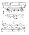
- FIGS. 7 and 8 are concerned with the storage of the rod-shaped guide member 11 and the bearing pin 61 of the telescopic extension 59 on the rear side wall of the cooking appliance muffle 1.
- each side a wall element 21 is arranged with corresponding mounting holes 19.
- the guide elements 11 and the telescopic extensions 59 are mounted in the manner of a floating bearing. This means that the respective rod end or the bearing journal 61 can move in a depth direction and thus heat-related stresses are avoided.
- the wall element 21 is according to the FIG. 8 formed as an angled U-profile part of a steel sheet with a large heat-resistant rigidity.
- the U-profile part 21 has at its one leg a right angle bent abutment flange 77.
- the air guide plate 81 separates a ring heater, not shown, and a fan from the cooking chamber. As a result of this mounting on the air guide plate 81, it is achieved that no additional openings have to be formed for fastening the U-profile part 81, for mounting the telescopic extension 59 or for mounting the guide element 11 in the muffle rear wall 17.
- the rear side wall of the cooking appliance muffle 1 is according to the FIGS. 7 and 8 from the muffle rear wall 17, the air guide plate 81 and the garraumayne remedyen wall elements 21st
- the angled U-profile part 21 also has a mounting flange 83. This is offset relative to the abutment flange 77 in the direction of the cooking chamber.
- the mounting holes 19 for the guide elements 11 and for the bearing pin 61 of the telescopic extension 59 are formed in a vertical row.
- each of the mounting holes 19 includes a cup-shaped edge embossing or a collar 85 which projects into the cooking chamber. This collar 85 serves as an abutting edge during the insertion of the bearing journal 61 or of the rod end 54.
- an additional aperture 87 is set on the wall element 21 in order to shield the U-profile part 21 from the cooking space.
- the panel 87 is designed as a U-shaped sheet steel profile part, which has corresponding to the mounting holes 19 of the U-profile part 21 aperture 89. Their diameter is made slightly larger than the diameter of the collar 85 of the mounting opening 19.
- the cup-shaped collar 85 protrudes in the assembled state according to the FIG. 7 through the aperture 89 in the oven.
- the collar 85 can thus fulfill its function as an insertion aid for the bearing journal 61 or the rod end 54.
- the cooking chamber facing surface of the aperture 87 is surface-finished according to the muffle walls, ie provided in the present case with an enamel layer.
- the aperture 87 together with the wall element 23 optically largely fades into the background.
- the aperture 87 is not directly in contact with the air guide plate 81. Rather, the aperture is slight, ie spaced at least without contact from the air guide plate 81. Corresponding damage to the enamel layer of the air guide plate 81 through the aperture 87 can be avoided.
Landscapes
- Engineering & Computer Science (AREA)
- Chemical & Material Sciences (AREA)
- Combustion & Propulsion (AREA)
- Mechanical Engineering (AREA)
- General Engineering & Computer Science (AREA)
- Baking, Grill, Roasting (AREA)
Description
- Die Erfindung betrifft ein Gargerät mit einer Gerätemuffel, in der an zumindest einer Muffelwand zumindest ein Zubehörteil gehaltert ist, das einen Lagerbolzen aufweist, der zur Halterung des Zubehörteiles durch eine Montageöffnung geführt ist.
- Aus
US 2,944,139 ist ein gattungsgemäßes Gargerät mit einer Gerätemuffel bekannt. An den Seitenwänden der Muffel sind in horizontaler Richtung Stäbe gehaltert. Diese Stäbe tragen Gestelle für Gargutbehältnisse, wie etwa ein Backblech. Die Stäbe sind jeweils in Montageöffnungen der Muffelseitenwand und der Muffelrückwand eingehängt. - Die Aufgabe der Erfindung besteht darin, ein Haushaltsgerät, insbesondere Gargerät, mit einer Gerätemuffel bereitzustellen, bei dem ein Garbetrieb wärmetechnisch günstig durchführbar ist.
- Die Aufgabe ist durch ein Gargerät mit den Merkmalen des Patentanspruches 1 gelöst. Gemäß dem kennzeichnenden Teil des Patentanspruches 1 ist garrauminnenseitig ein Wandelement vorgesehen, in dem die Montageöffnung für den Lagerbolzen ausgebildet ist. Darüber hinaus weist das Wandelement einen von der Muffelwand beabstandeten Montageflansch auf. In dem Montageflansch kann die zumindest eine Montageöffnung für den Lagerbolzen des Zubehörteils angeordnet sein. Da erfindungsgemäß die Montageöffnung nicht in der Muffelwand ausgebildet ist, bleibt die Muffelseitenwand nach außen geschlossen. Während des Garbetriebs ist daher ein Wärmeverlust aus dem Garraum reduziert. Ferner bleibt durch den Abstand zwischen dem Montageflansch und der Muffelwand genügend Raum hinter dem Wandelement, um etwa eine Lagerbuchse in der Montageöffnung anzubringen.
- Bevorzugt ist es, wenn in dem garrauminnenseitigen Wandelement eine Anzahl von Montageöffnungen für Lagerbolzen mehrerer Zubehörteile ausgebildet ist. In diesem Fall können durch Anbringung des Wandelements an einer Muffelwand in einem einzigen Montageschritt eine Anzahl von Montageöffnungen für mehrere Zubehörteile ausgebildet werden. Dabei ist es vorteilhaft, wenn das Wandelement als ein abgewinkeltes Profilteil ausgebildet ist. Dies gewährleistet bei einer Wärmebeanspruchung eine ausreichende Steifigkeit des Wandelements. Vorteilig kann das Wandelement zumindest einen Anlageflansch aufweisen. Dieser kann flächig mit der Seitenwand in Anlage sein. In dieser Weise kann das Wandelement mit seinem Anlageflansch formstabil an der Seitenwand gehaltert werden.
- Der Lagerbolzen kann nach Art eines Loslagers mit einem Längsspiel in der Montageöffnung des Montageflansches gelagert sein. Hierbei ist von Vorteil, wenn ein die Montageöffnung umziehender Kragen napfartig in den Garraum ragt. Dieser napfartig ausgebildete Kragen vereinfacht das Einführen des Lagerbolzens in die Montageöffnung. Gleichzeitig dient er als Stoßkante bei dem Einführen des Lagerbolzens des Zubehörteils.
- Dem Wandelement kann eine Blende zugeordnet sein, die das Wandelement gegenüber dem Garraum verdeckt. Dabei kann die Oberfläche der Blende entsprechend der Oberfläche der Muffelwände ausgebildet sein. Auf diese Weise tritt die Blende zusammen mit dem Wandelement optisch in den Hintergrund. Für den Fall einer innenseitigen Emaillierung der Gerätemuffel kann etwa die Oberfläche der Blende entsprechend emailliert sein.
- Besonders bevorzugt ist es, wenn das Wandelement als ein Stahlblech mit geringer Materialstärke ausgebildet ist. Dadurch kann in wärmetechnisch günstiger Weise ein zu großer Materialeintrag in die Gerätemuffel vermieden werden.
- Entsprechend der Montageöffnung des Wandelements kann die Blende zumindest eine Blendenöffnung aufweisen. Dabei ist es besonders bevorzugt, wenn der napfartig ausgebildete Kragen der Montageöffnung durch die Blendenöffnung hindurch in den Garraum ragt. Der als Einführhilfe wirkende napfartig ausgebildete Kragen kann somit nachteilige Stöße auf die gegebenenfalls aufwendig bearbeitete Oberfläche der Blende reduzieren.
- Um beim Einbau des Wandelements bzw. der Blende in die Gerätemuffel eine Beschädigung der Oberfläche der Muffelwand zu vermeiden, ist im montierten Zustand die Blende geringfügig von der Muffelwand beabstandet. Die Blende ist daher berührungsfrei gegenüber der Muffelwand angeordnet.
- Die Muffelwand kann zusammen mit dem garrauminnenseitigen Wandelement zumindest doppelwandig ausgeführt sein. Im Sinne einer Bauteilreduzierung ist es besonders bevorzugt, wenn das garrauminnenseitige Wandelement als eine Luftführungsplatte ausgebildet ist. Die Luftführungsplatte trennt einen Heizkörper und/oder ein Gebläse von dem Garraum ab. In diesem Fall kann die ohnehin im Garraum vorhandene Luftführungsplatte gleichzeitig als ein Träger für das Zubehörteil dienen.
- In einer weiteren Ausführungsform ist zwischen dem garrauminnenseitigen Wandelement und der Muffetwand die Luftführungsplatte angeordnet. Damit kann das Wandelement unmittelbar mit der Luftführungsplatte verbunden werden. Wärmetechnisch nachteilige Befestigungslöcher für das Wandelement können so in der Muffelwand verhindert werden.
- Nachfolgend ist ein Ausführungsbeispiel der Erfindung anhand der beigefügten Figuren beschrieben. Es zeigen:
- Figur 1
- in einer perspektivischen Ansicht ein Gargerät mit frontseitig offener Gargerätetür;
- Figur 2
- in einer vergrößerten Schnittansicht die Einzelheit I aus der
Figur 1 ; - Figur 3
- in einer perspektivischen Schnittansicht eine Lagerbuchse für ein Führungselement;
- Figur 4
- in einer Seitenschnittdarstellung eine Abwandlung der Lagerbuchse;
- Figur 5
- in einer perspektivischen Ansicht das Führungselement;
- Figur 6
- in einer vergrößerten Darstellung die Einzelheit II aus der
Figur 1 ; - Figur 7
- in einer vergrößerten Darstellung ein Wandelement zur muffelrückwandseitigen Halterung der Führungselemente; und
- Figur 8
- in einer perspektivischen Explosionsdarstellung das Wandelement mit einer muffelrückwandseitigen Luftführungsplatte.
- In der
Figur 1 ist ein Gargerät mit einer innenseitig mit einer Emailleschicht versehenen Gargerätemuffel 1 dargestellt. Das Gargerät weist eine Schwenktür 3 zum Schließen einer frontseitigen Muffelöffnung 5 auf. Die Schwenktür 3 ist im geschlossenen Zustand in Anlage mit einem die Muffelöffnung 5 umziehenden Frontflansch 7. An den gegenüberliegenden Seitenwänden 9 der Gargerätemuffel 1 sind korrespondierende seitliche Führungselemente 11 sowie ein später beschriebenes Auszugssystem, bestehend aus zwei Teleskopauszügen 59 gehaltert. Die Teleskopauszüge 59 sind in einer obersten von vier horizontalen Garraumebenen gehaltert. In den folgenden vier unteren Garraumebenen sind jeweils die seitlichen Führungselemente 11 gehaltert. Auf den beiden korrespondierenden untersten Führungselementen 11 stützt sich ein Backblech 13 ab, das teilweise aus der Gargerätemuffel 1 herausgeschoben ist. Jedes der Führungselemente 11 ist als ein stabförmiges Stahlprofilteil bzw. Fertigungsteil ausgebildet, das einen kreisförmigen Querschnitt aufweist und aus einem Vollmaterial besteht. - Die Führungselemente 11 und/oder die Teleskopauszüge 59 können von einem Benutzer in beliebiger Weise in der Gargerätemuffel 1 angeordnet werden. Hierzu sind die Führungselemente 11 und Teleskopauszüge 59 sind muffelfrontseitig jeweils in einer Lagerbuchse 15 eingehängt. Im Bereich einer Muffelrückwand 17 sind die Führungselemente 11 jeweils in einer Montageöffnung 19 eines Wandelements 21 gelagert. Sowohl die Führungselemente 11 als auch die Teleskopauszüge 59 sind werkzeugfrei vom Benutzer aus der Muffel 1 zu lösen.
- Die muffelfrontseitige Halterung der Führungselemente 11 in den Lagerbuchsen 15 ist in der
Figur 2 im Detail dargestellt. Demzufolge ist die in derFigur 3 als Einzelteil dargestellte Lagerbuchse 15 hohlzylindrisch mit einem äußeren Randflansch 23 ausgebildet. Dieser stützt sich innerhalb eines Garraumes der Muffel 1 innenseitig auf der Muffelseitenwand 9 ab. Die Muffelseitenwand 9 besteht aus einem dünnen Stahlblech mit einer Wandstärke im Bereich zwischen 0,3 bis 0,7 mm. Wie auch aus derFigur 3 hervorgeht, geht der Randflansch 23 der Lagerbuchse 15 garrauminnenseitig in einen Einführzylinder 25 über. Der Einführzylinder 25 dient als Einführhilfe für einen Lagerbolzen 27, der an einem Stabende des stabförmigen Führungselements 11 ausgebildet ist. Im Bereich des Einführzylinders 25 der Lagerbuchse ist gemäß derFigur 3 ein Innensechskantprofil vorgesehen, um mit einem entsprechenden Werkzeug die Lagerbuchse 15 in eine Öffnung 10 der Muffelseitenwand 9 montieren zu können. - Eine dem Garraum 25 zugewandte Einführöffnung der Lagerbuchse 15 ist von einem Frontflansch 31 stirnseitig umzogen. Der Frontflansch 31 der Lagerbuchse 15 ist vom Randflansch 23 axial beabstandet. Dazwischen ist eine Ringnut 33 ausgebildet. Diese dient, wie später beschrieben ist, als ein Halterungsabschnitt zum Einhängen der Teleskopauszüge 59.
- Die Lagerbuchse 15 ist am Außenumfang mit einem Außengewinde 35 versehen, über das die Lagerbuchse gemäß der
Figur 2 in die Muffelseitenwand 9 eingeschraubt ist. Ein korrespondierendes Gegengewinde 39 ist allerdings nicht in der dünnwandigen Muffelseitenwand 9 selbst ausgebildet. Vielmehr ist das Gegengewinde 39 in einem Sicherungselement 37 ausgebildet. Das Sicherungselement 37 ist gemäß derFigur 2 außenseitig mit der Muffelseitenwand 9 in Anlage. Es ist als ein längliches Profilteil mit den entsprechenden Gegengewinden 39 für die Lagerbuchsen 15 ausgebildet. Das Profilteil 17 ist ein im Querschnitt U-profilförmiges Stahlblech, wodurch es auch bei thermischer Belastung verwindungssteif und formstabil bleibt. Jedes der Gegengewinde 39 ist dabei nach Art einer Blechmutter in dem Profilteil 37 eingearbeitet. Das Profilteil 37 erstreckt sich in einer vertikalen Richtung über alle in derFigur 1 gezeigten Lagerbuchsen 15 einer Muffelseitenwand 9. Durch die großflächige Anlage des Profilteils 37 an der Außenseite der Seitenwand 9 sind die Lagerbuchsen 15 stabil gegenüber Kippmomente befestigt, und zwar trotz der dünnwandigen Muffelseitenwand 9. In etwa mittig zwischen den beiden Schenkeln des U-profilförmigen Sicherungselements 37 sind die Gegengewinde 39 ausgebildet. - Die Lagerbuchse 15 ist mit ihrem Außengewinde 35 mit einem Spiel durch die Öffnung 10 der Muffelseitenwand 9 geführt. Die Lagerbuchse 15 ist daher nicht unmittelbar mit der Muffelseitenwand 9 verschraubt. Vielmehr ist die Muffelseitenwand 9 zwischen dem Sicherungselement 37 und dem Randflansch 23 der Lagerbuchse 15 geklemmt.
- In den beiden Schenkeln 41 des U-profilförmigen Profilteils 37 sind gemäß der
Figur 2 hakenförmige Aussparungen 43 eingeschnitten, in denen eine Drahtfeder 45 gehaltert ist. Diese erstreckt sich quer zu den Schenkeln 41 des Profilteiles 37. Dabei ist in derFigur 2 der Lagerbolzen 27 des Führungselements 11 zwischen zwei Federschenkeln der Drahtfeder 45 sicher verrastet. Hierzu weist der Lagerbolzen 27 des Führungselements 11 an seinem Einführende eine Rastnut 47 auf, in die die beiden Federschenkel der Drahtfeder 45 eingerastet sind. An seinem Einführende ist der Lagerbolzen 27 mit einem Einführkonus 49 ausgebildet, der als Einführhilfe für den Lagerbolzen 27 dient. Ein Übergangsabschnitt 46 zwischen dem Einführkonus 49 und der Rastnut 47 weitet sich dabei in Richtung des Einführkonus 49 konusartig aus. - Wie aus der
Figur 2 hervorgeht, ist der Lagerbolzen 27 des Führungselements 11 auf einen Durchmesser reduziert, der eine formschlüssige Lagerung in der Lagerbuchse 15 gestattet. Dadurch ist eine spielfreie Halterung des Führungselements 11 in der Lagerbuchse 15 erreicht. Diese wird weiter unterstützt durch eine Anlageschulter 51 des Lagerbolzens 27, die in Anlage mit dem Frontflansch 31 der Lagerbuchse 15 ist. - Zusätzlich drücken in der
Figur 2 die beiden gegenüberliegenden Federschenkel der Drahtfeder 45 auf den konusartigen Übergangsabschnitt 46 des Lagerbolzens 27. Dadurch wird der Lagerbolzen 27 mit einer Druckkraft in die Lagerbuchse 15 gezogen und permanent gegen den Frontflansch 31 der Lagerbuchse 15 gedrückt. - In der
Figur 4 ist die Lagerbuchse 15 in einer Abwandlung dargestellt. Im Unterschied zu der in derFigur 3 dargestellten Lagerbuchse ist in der Lagerbuchse derFigur 4 auf den Frontflansch 31 verzichtet. Die Lagerbuchse 15 weist daher garrauminnenseitig lediglich den Randflansch 23 auf. Wie anhand derFigur 2 erläutert, wird die Anlageschulter 51 in entsprechender Weise gegen den Randflansch 23 des Lagerbolzens 27 gedrückt. - Als weiteren Unterschied zu der vorangegangenen Ausführungsform ist das garraumaußenseitige Ende der in der
Figur 4 gezeigten Lagerbuchse 15 geschlossen. Somit ist bei herausgenommenem Führungselement 11 eine Wärmeableitung aus dem Garraum durch die Lagerbuchse 15 reduziert. Als das Sicherungselement 37 für die Lagerbuchse 15 ist anstelle eines einzigen Profilteils für alle Lagerbuchsen 15 jeweils eine Sicherungsmutter vorgesehen. Diese ist in derFigur 4 auf das Außengewinde 35 der Lagerbuchse 15 geschraubt. Um ein Einrasten des Lagerbolzens 27 in die Lagerbuchse 15 zu ermöglichen, ist im Bereich des geschlossenen Endes der Lagerbuchse 15 in deren Außenumfang ein Schlitz 52 vorgesehen. In dem Schlitz 52 ist ein Federschenkel der Drahtfeder 45 eingesetzt, der in die Rastnut 47 des Lagerbolzens 27 eingreift. - In der
Figur 5 ist ein aus der Gargerätemuffel 1 herausgenommenes Führungselement 11 dargestellt. Der Lagerbolzen 27 ist an einem Stabende des Führungselements 11 mit einem reduzierten Durchmesser ausgebildet. Da das Führungselement 11 aus einem Vollmaterial besteht, kann fertigungstechnisch einfach, etwa mittels einer Drehmaschine der Lagerbolzen 27 an dem Stabende ausgebildet werden. Das mit dem Lagerbolzen 27 versehene Stabende des Führungselements 11 ist zudem winkelförmig abgebogen. Eine hierfür notwendige Biegeformung ist im Vergleich zu einem Hohlmaterial bei dem hier verwendeten Vollmaterial fertigungstechnisch problemlos durchführbar. - Die Führungselemente 11 und Teleskopauszüge 59 sind jeweils unabhängig voneinander ausgebildet und in die Muffel 1 eingesetzt, wie es aus der
Figur 1 ersichtlich ist. Demzufolge können sie auch unabhängig voneinander aus dem Garraum genommen werden, sofern sie nicht zur Halterung eines Gargutträgers benötigt werden. Dadurch kann wärmetechnisch vorteilhaft ein Materialeintrag in die Gargerätemuffel 1 möglichst gering gehalten werden. - Das L-förmig ausgebildete Führungselement 11 ist mit einem entlang der Muffelseitenwand 9 langgestreckten Schenkel ausgebildet, der zur Führung und Abstützung von Einschubteilen dient. Die L-Form des Führungselements 11 ermöglicht es, das Führungselement 11 mit seinem muffelrückseitigen Stabende 54 an der Muffelrückwand 17 und mit dem abgebogenen muffelfrontseitigen Stabende an der Muffelseitenwand 9 zu haltern. Durch diese Halterung an zwei verschiedenen Muffelwänden ist das Führungselement 11 widerstandsfähiger gegenüber Kippmomenten.
- Muffelfrontseitig ist am Führungselement 11 ein Höhenanschlag 53 als ein Kippschutz für Einschubteile vorgesehen. Dieser ist als ein gebogener Stahldrahtbügel mit seinen beiden Enden in entsprechende Bohrungen des Führungselements 11 gepresst. Entsprechend ist im Bereich des muffelrückseitigen Stabendes 54 um 90° versetzt eine weitere Bohrung im Führungselement 11 ausgebildet. In diese ist ein Stahlstift eingepresst, der als ein Einschubanschlag 55 für ein Einschubteil dient.
- In der
Figur 6 ist eine alternative Verwendung der Lagerbuchse 15 dargestellt. Demzufolge ist kein stabförmiges Führungselement 11 in die Lagerbuchse 15 eingesteckt. Vielmehr ist alternativ dazu eine Halteplatte 57 des in derFigur 1 gezeigten Teleskopauszuges 59 in die Ringnut 33 der Lagerbuchse 15 eingehängt. Der Teleskopauszug 59 weist gemäß derFigur 1 einen hinteren Zapfen 61 zur Halterung an der Muffelrückwand 17 auf. Der Zapfen 61 ist wie das hintere Stabende 54 eines der Führungselemente 11 ausgebildet. - Die muffelfrontseitige Halteplatte 57 ist als ein Stahlblech mit einem gestanzten Langloch 63 ausgebildet. Das Langloch 63 erstreckt sich senkrecht zu dem langgestreckten Teleskopauszug 59 und dient zum Einhängen der Halteplatte 57 in die Ringnut 33 der Lagerbuchse 15. Hierzu ist das Langloch 63 wie ein umgekehrtes Schlüsselloch mit einem aufgeweiteten Einführabschnitt 65 und einem schmalen Sicherungsabschnitt 67 in die Halteplatte 57 gestanzt. Der Durchmesser des aufgeweiteten Einführabschnitts 65 ist größer als der Durchmesser des Frontflansches 31 der Lagerbuchse 15. Demzufolge kann die Halteplatte 57 einfach über den Frontflansch 31 der Lagerbuchse 15 geführt und in die Ringnut 33 eingehängt werden. Die Wandstärke der Halteplatte 57 ist dabei kleiner als eine Nutbreite der Ringnut 33 der Lagerbuchse 15. Die gegenüberliegenden seitlichen Begrenzungskanten des Sicherungsabschnittes 67 sind in der
Figur 6 innerhalb der Ringnut 33 der Lagerbuchse 15 angeordnet. Dadurch ist eine Axialbewegung der eingehängten Halteplatte 57 entlang der Lagerbuchse 15 verhindert. - Unterhalb des Langloches 63 ist eine Blattfeder 69 mittels eines Niets 71 mit der Halteplatte 57 vernietet. Die Blattfeder 69 wirkt wie ein Riegelelement. In der
Figur 6 ist die Blattfeder 69 in ihrer Verriegelungsposition gezeigt. In dieser Position ist eine obere Verriegelungskante 73 der Blattfeder 69 in Anlage mit einem Umfang des Frontflansches 31 der Lagerbuchse 15 oder geringfügig davon beabstandet. Eine versehentliche Bewegung der Halteplatte 57 nach oben ist somit durch die Blattfeder 69 verhindert. Entsprechend ist deshalb ein versehentliches Lösen der Halteplatte 57 von der Lagerbuchse 15 verhindert. - Die Blattfeder 69 weist gemäß der
Figur 6 einen Betätigungsabschnitt 75 auf. Dieser kann in Richtung des gezeigten Pfeils eingedrückt werden, wodurch die Verriegelungskante 73 in Richtung des gezeigten Pfeils in den Garraum geschwenkt wird. In dieser Position ist die Verriegelungskante 73 der Blattfeder 69 außer Eingriff mit der Lagerbuchse 15. Die Halteplatte 57 des Teleskopauszugs 59 kann daher für eine Entnahme des Teleskopauszugs 59 angehoben werden, so dass die Lagerbuchse 15 aus dem Einführabschnitt 65 der Halteplatte 57 herausgeführt werden kann. - Bei herausgenommenem Teleskopauszug 59 liegt die Blattfeder 69 mit ihrer Verriegelungskante 73 direkt auf der Halteplatte 57 und überlappt den Einführabschnitt 65 des Langlochs 63. Für ein erneutes Einhängen des Teleskopauszuges 59 ist die Lagerbuchse 15 durch den Langloch-Einführabschnitt 65 der Halteplatte 57 zu führen. Auf diese Weise drückt die Lagerbuchse 15 die Blattfeder 69 mit ihrer Verriegelungskante 73 von der Halteplatte 57 weg.
- Anschließend kann der Teleskopauszug 59 vom Benutzer geringfügig gesenkt werden, bis sich die Lagerbuchse 15 im schmalen Sicherungsabschnitt 67 des Langloches 63 befindet, wie es in der
Figur 6 gezeigt ist. In diesem Zustand ist die Blattfeder 69 selbsttätig in ihre Verriegelungsposition zurückgesprungen. Die Blattfeder 69 kann erst aus der Verriegelungsposition in eine Entriegelungsposition gekippt werden, wenn ein Benutzer auf ihren Betätigungsabschnitt 75 drückt. In der Entriegelungsposition kann die Halteplatte 57 des Teleskopauszuges 59 vom Benutzer geringfügig angehoben werden. Dabei wird die Lagerbuchse 15 im Einführabschnitt 65 des Langloches 63 angeordnet. In diesem Zustand kann die Halteplatte 59 durch eine Axialbewegung von der Lagerbuchse 15 gelöst werden. - Die
Figuren 7 und 8 befassen sich mit der Lagerung des stabförmigen Führungselements 11 und des Lagerzapfens 61 des Teleskopauszugs 59 an der hinteren Seitenwand der Gargerätemuffel 1. Wie bereits erwähnt, ist hierzu garrauminnenseitig jeweils seitlich ein Wandelement 21 mit entsprechenden Montageöffnungen 19 angeordnet. In den Montageöffnungen 19 sind die Führungselemente 11 und der Teleskopauszüge 59 nach Art eines Loslagers gelagert. D. h., dass sich das jeweilige Stabende bzw. der Lagerzapfen 61 in einer Tiefenrichtung bewegen kann und somit wärmebedingte Spannungen vermieden werden. Das Wandelement 21 ist gemäß derFigur 8 als ein abgewinkeltes U-Profilteil aus einem Stahlblech mit einer großen wärmeresistenten Steifigkeit ausgebildet. Das U-Profilteil 21 weist an seinem einen Schenkel einen rechtwinklig abgebogenen Anlageflansch 77 auf. Dieser ist über Feststellschrauben 79 großflächig in Anlage mit einer Montagefläche einer muffelrückwandseitigen Luftführungsplatte 81 montiert. Die Luftführungsplatte 81 trennt einen nicht dargestellten Ringheizkörper sowie ein Gebläse von dem Garraum ab. Durch diese Montage an der Luftführungsplatte 81 ist erreicht, dass keinerlei zusätzliche Öffnungen zur Befestigung des U-Profilteils 81, zur Lagerung des Teleskopauszugs 59 oder zur Lagerung des Führungselements 11 in der Muffelrückwand 17 ausgebildet werden müssen. Die hintere Seitenwand der Gargerätemuffel 1 besteht gemäß derFiguren 7 und 8 aus der Muffelrückwand 17, der Luftführungsplatte 81 und den garrauminnenseitigen Wandelementen 21. - Das abgewinkelte U-Profilteil 21 weist darüber hinaus einen Montageflansch 83 auf. Dieser ist gegenüber dem Anlageflansch 77 in Richtung auf den Garraum versetzt. In dem Montageflansch 83 sind in einer vertikalen Reihe die Montageöffnungen 19 für die Führungselemente 11 bzw. für den Lagerzapfen 61 des Teleskopauszugs 59 ausgebildet. Wie insbesondere aus der
Figur 8 hervorgeht, umzieht jede der Montageöffnungen 19 eine napfartige Randprägung bzw. ein Kragen 85, der in den Garraum ragt. Dieser Kragen 85 dient als Stoßkante bei der Einführung des Lagerzapfens 61 bzw. des Stabendes 54. - Gemäß den
Figuren 7 und 8 ist eine zusätzliche Blende 87 auf das Wandelement 21 gesetzt, um das U-Profilteil 21 gegenüber dem Garraum abzuschirmen. Gemäß den Figuren ist dabei die Blende 87 als ein U-förmiges Stahlblech-Profilteil gestaltet, das entsprechend den Montageöffnungen 19 des U-Profilteils 21 Blendenöffnungen 89 aufweist. Deren Durchmesser ist etwas größer gestaltet als der Durchmesser des Kragens 85 der Montageöffnung 19. Damit ragt der napfartige Kragen 85 im montierten Zustand gemäß derFigur 7 durch die Blendenöffnung 89 in den Garraum. Trotz der vorgelagerten Blende 87 kann somit der Kragen 85 seine Funktion als Einführhilfe für den Lagerzapfen 61 bzw. das Stabende 54 erfüllen. - Die dem Garraum zugewandte Oberfläche der Blende 87 ist entsprechend der Muffelwände oberflächenbearbeitet, d. h. im vorliegenden Fall mit einer Emailleschicht versehen. Dadurch tritt die Blende 87 zusammen mit dem Wandelement 23 optisch weitgehend in den Hintergrund. Um montagebedingte Kratzer auf der Luftführungsplatte 81 zu vermeiden, ist die Blende 87 nicht unmittelbar in Anlage mit der Luftführungsplatte 81. Vielmehr ist die Blende geringfügig, d. h. zumindest berührungsfrei von der Luftführungsplatte 81 beabstandet. Entsprechende Beschädigungen der Emailleschicht der Luftführungsplatte 81 durch die Blende 87 können dadurch vermieden werden.
Claims (14)
- Gargerät mit einer Gerätemuffel (1), in der an zumindest einer Muffelwand (9, 17) zumindest ein Zubehörteil (11, 59) gehaltert ist, das einen Lagerbolzen (27, 54, 61) aufweist, der zur Halterung des Zubehörteiles (11, 59) durch eine Montageöffnung (19) geführt ist, dadurch gekennzeichnet, dass garrauminnenseitig ein Wandelement (21) vorgesehen ist, in dem die Montageöffnung (19) für den Lagerbolzen (27, 54, 61) ausgebildet ist und das Wandelement (21) einen von der Muffelwand (9, 17) beabstandeten Montageflansch (83) aufweist, in dem die Montageöffnung (19) ausgebildet ist.
- Gargerät nach Anspruch 1, dadurch gekennzeichnet, dass das Wandelement (21) als ein abgewinkeltes Profilteil ausgebildet ist.
- Gargerät nach einem der vorhergehenden Ansprüche, dadurch gekennzeichnet, dass der Wandelement (21) zumindest einen Anlageflansch (77) aufweist, der mit der Muffelwand (9, 17) in Anlage ist.
- Gargerät nach einem der vorhergehenden Ansprüche, dadurch gekennzeichnet, dass die Montageöffnung (19) von einem napfartig in den Garraum ragenden Kragen (85) umzogen ist.
- Gargerät nach einem der vorhergehenden Ansprüche, dadurch gekennzeichnet, dass dem Wandelement (21) eine Blende (87) zugeordnet ist, die das Wandelement (21) gegenüber dem Garraum verdeckt.
- Gargerät nach Anspruch 5, dadurch gekennzeichnet, dass die Oberfläche der Blende (87) entsprechend der garrauminnenseitigen Oberfläche der Muffelwand (9, 17) ausgebildet ist.
- Gargerät nach einem der Ansprüche 5 oder 6, dadurch gekennzeichnet, dass die Blende (87) zumindest eine mit der Montageöffnung (19) des Wandelements (21) korrespondierende Blendenöffnung (89) aufweist.
- Gargerät nach Anspruch 7, dadurch gekennzeichnet, dass der napfartig ausgebildete Kragen (85) der Montageöffnung (19) des Wandelements (21) durch die Blendenöffnung (89) ragt.
- Gargerät nach einem der Ansprüche 5 bis 8, dadurch gekennzeichnet, dass die Blende (87) zumindest geringfügig von der Muffelwand (17) beabstandet ist.
- Gargerät nach einem der vorhergehenden Ansprüche, dadurch gekennzeichnet, dass die Muffelwand (17) zusammen mit dem garrauminnenseitigen Wandelement (21) zumindest doppelwandig ausgebildet ist.
- Gargerät nach Anspruch 10, dadurch gekennzeichnet, dass zwischen dem garrauminnenseitigen Wandelement (21) und der als Muffelrückwand (17) ausgeführten Muffelwand eine Luftführungsplatte (81) angeordnet ist, die ein Gebläse und/oder einen Heizkörper vom Garraum verdeckt.
- Gargerät nach einem der vorhergehenden Ansprüche, dadurch gekennzeichnet, dass in dem Wandelement (21) eine Anzahl von Montageöffnungen (19) für die Lagerbolzen (54, 61) der Zubehörteile (11, 59) ausgebildet ist.
- Gargerät nach einem der Ansprüche 1 bis 10, dadurch gekennzeichnet, dass das garrauminnenseitige Wandelement als die Luftführungsplatte ausgebildet ist.
- Gargerät nach einem der vorhergehenden Ansprüche, dadurch gekennzeichnet, dass die zumindest eine Muffelwand (9, 17) eine Muffelrückwand (17) umfasst.
Applications Claiming Priority (2)
| Application Number | Priority Date | Filing Date | Title |
|---|---|---|---|
| DE102004001686 | 2004-01-12 | ||
| DE200410001686 DE102004001686A1 (de) | 2004-01-12 | 2004-01-12 | Haushaltsgerät, insbesondere Gargerät |
Publications (2)
| Publication Number | Publication Date |
|---|---|
| EP1553351A1 EP1553351A1 (de) | 2005-07-13 |
| EP1553351B1 true EP1553351B1 (de) | 2015-04-29 |
Family
ID=34585400
Family Applications (1)
| Application Number | Title | Priority Date | Filing Date |
|---|---|---|---|
| EP20050100113 Expired - Lifetime EP1553351B1 (de) | 2004-01-12 | 2005-01-11 | Haushaltsgerät, insbesondere Gargerät |
Country Status (3)
| Country | Link |
|---|---|
| EP (1) | EP1553351B1 (de) |
| DE (1) | DE102004001686A1 (de) |
| ES (1) | ES2536718T3 (de) |
Families Citing this family (8)
| Publication number | Priority date | Publication date | Assignee | Title |
|---|---|---|---|---|
| DE102004021046A1 (de) * | 2004-04-29 | 2005-11-24 | BSH Bosch und Siemens Hausgeräte GmbH | Haushaltsgeräteträgervorrichtung |
| DE102006062070B4 (de) * | 2006-12-29 | 2018-10-25 | BSH Hausgeräte GmbH | Gargerätevorrichtung und Gargerät |
| DE202008010190U1 (de) * | 2008-07-30 | 2009-12-10 | Paul Hettich Gmbh & Co. Kg | Auszugsvorrichtung für ein Haushaltsgerät |
| EP3568643B1 (de) * | 2017-01-12 | 2021-07-07 | Electrolux Appliances Aktiebolag | Ein gargerät, insbesondere ein haushaltsgargerät |
| DE102019205677A1 (de) * | 2019-04-18 | 2020-10-22 | BSH Hausgeräte GmbH | Lagerbuchse für ein Haushaltsgerät mit einem Grundkörper und einer Hülse mit radialem Federelement, Baugruppe sowie Haushaltsgerät |
| EP4092331A1 (de) * | 2021-05-17 | 2022-11-23 | Miele & Cie. KG | Befestigungssystem für ein aufnahmegitter eines gargeräts mit garraum und gargerät |
| WO2023234884A1 (en) * | 2022-06-03 | 2023-12-07 | Femas Metal San. Ve Tic. A.S. | Oven containing support elements for holding wire shelves |
| BE1031031B1 (de) * | 2022-11-11 | 2024-06-10 | Miele & Cie | Haltevorrichtung für ein Funktionsteil eines Gargeräts mit einem Garraum, System für ein Gargerät und Gargerät |
Family Cites Families (5)
| Publication number | Priority date | Publication date | Assignee | Title |
|---|---|---|---|---|
| US2944139A (en) | 1959-01-27 | 1960-07-05 | Philco Corp | Cooking range oven with removable liner |
| US3318299A (en) * | 1965-12-02 | 1967-05-09 | Gen Electric | Self-cleaning oven with removable panels |
| JPS5816127A (ja) * | 1981-07-21 | 1983-01-29 | Matsushita Electric Ind Co Ltd | 高周波加熱装置 |
| DE3628763A1 (de) * | 1986-08-25 | 1988-03-03 | Bosch Siemens Hausgeraete | Vorrichtung in backoefen zur auflage von garguttraegern |
| DE19859986A1 (de) | 1998-12-23 | 2000-06-29 | Bsh Bosch Siemens Hausgeraete | Teleskopauszugsvorrichtung für Haushaltsgeräte und Möbel |
-
2004
- 2004-01-12 DE DE200410001686 patent/DE102004001686A1/de not_active Withdrawn
-
2005
- 2005-01-11 EP EP20050100113 patent/EP1553351B1/de not_active Expired - Lifetime
- 2005-01-11 ES ES05100113.9T patent/ES2536718T3/es not_active Expired - Lifetime
Also Published As
| Publication number | Publication date |
|---|---|
| DE102004001686A1 (de) | 2005-08-04 |
| EP1553351A1 (de) | 2005-07-13 |
| ES2536718T3 (es) | 2015-05-27 |
Similar Documents
| Publication | Publication Date | Title |
|---|---|---|
| EP2254443B1 (de) | Teleskopierbare auszugsführung | |
| EP1840473A2 (de) | Teleskopauszugsvorrichtung zur Befestigung an einem in dem Behandlungsraum eines Haushaltsgeräts angeordneten Traggestell | |
| EP2703731B1 (de) | Lagerbuchse für ein Haushaltsgerät mit einem pilzförmigen Basiskörper mit einem frontseitig zugänglichen Hohlraum sowie Haushaltsgerät | |
| EP3681347B1 (de) | Blendenträger und schubkasten | |
| EP4293287A1 (de) | Teleskopauszug | |
| EP3101347B1 (de) | Anordnung mit einer schienenauszugseinrichtung und einem gargerätebauteil, gargerät mit einer derartigen anordnung sowie verfahren zum bewegen einer schienenauszugseinrichtung | |
| EP1553352B1 (de) | Haushaltsgerät, insbesondere Gargerät sowie Herstellungsverfahren | |
| EP1553349B1 (de) | Haushaltsgerät, insbesondere Gargerät mit Haltevorrichtung | |
| EP1553350B1 (de) | Gargerät | |
| EP1553351A1 (de) | Haushaltsgerät, insbesondere Gargerät | |
| EP2592354B1 (de) | Gargerät mit einer in das Gehäuse des Gargeräts versenkbaren Tür | |
| EP3746709B1 (de) | Anordnung mit einer schienenauszugseinrichtung und einem gargerätebauteil und gargerät mit einer derartigen anordnung | |
| DE102009046573A1 (de) | Teleskopauszugsvorrichtung für ein Hausgerät, Hausgrät mit einer derartigen Teleskopauszugsvorrichtung sowie Verfahren zum Befestigen einer Teleskopauszugsvorrichtung an einem Traggestell zur Aufnahme zumindest eines Gargutträgers | |
| EP2634493B1 (de) | Tür für ein Haushaltsgerät zum Zubereiten von Lebensmitteln mit einem Trägerteil | |
| EP1553347B1 (de) | Haushaltsgerät, insbesondere Gargerät | |
| EP3012536B1 (de) | Gaskochmulde | |
| DE102008013004B4 (de) | Anordnung mit einem Kochfeld und einer Arbeitsplatte | |
| WO2020212161A1 (de) | Lagerbuchse für ein haushaltsgerät mit einem grundkörper und einer hülse mit radialem federelement, baugruppe sowie haushaltsgerät | |
| EP3519737B1 (de) | Baugruppe für einen gargutträger mit einem traggestell und eine schienenauszugsvorrichtung, sowie haushaltsgerät umfassend eine solche baugruppe | |
| EP3211324A1 (de) | Lagerbuchse für ein haushaltsgerät mit einem federelement, welches ein abdeckteil zum abdecken einer einfädelöffnung aufweist, baugruppe sowie haushaltsgerät | |
| DE102006062070B4 (de) | Gargerätevorrichtung und Gargerät | |
| EP4286749A1 (de) | Schnellbefestigungssystem für einen teleskopauszug | |
| EP1312868B1 (de) | Anordnung mit einer Kochmulde und einem Zwischenboden sowie Zwischenboden | |
| EP2357414B1 (de) | Hausgerät zum Zubereiten von Lebensmitteln mit einer Lagerbuchse | |
| DE102023135875B4 (de) | Teleskopauszug mit Schnellbefestigungselementen |
Legal Events
| Date | Code | Title | Description |
|---|---|---|---|
| PUAI | Public reference made under article 153(3) epc to a published international application that has entered the european phase |
Free format text: ORIGINAL CODE: 0009012 |
|
| AK | Designated contracting states |
Kind code of ref document: A1 Designated state(s): AT BE BG CH CY CZ DE DK EE ES FI FR GB GR HU IE IS IT LI LT LU MC NL PL PT RO SE SI SK TR |
|
| AX | Request for extension of the european patent |
Extension state: AL BA HR LV MK YU |
|
| 17P | Request for examination filed |
Effective date: 20060113 |
|
| AKX | Designation fees paid |
Designated state(s): AT BE BG CH CY CZ DE DK EE ES FI FR GB GR HU IE IS IT LI LT LU MC NL PL PT RO SE SI SK TR |
|
| 17Q | First examination report despatched |
Effective date: 20111220 |
|
| GRAP | Despatch of communication of intention to grant a patent |
Free format text: ORIGINAL CODE: EPIDOSNIGR1 |
|
| INTG | Intention to grant announced |
Effective date: 20141217 |
|
| RAP1 | Party data changed (applicant data changed or rights of an application transferred) |
Owner name: BSH HAUSGERAETE GMBH |
|
| GRAS | Grant fee paid |
Free format text: ORIGINAL CODE: EPIDOSNIGR3 |
|
| GRAA | (expected) grant |
Free format text: ORIGINAL CODE: 0009210 |
|
| AK | Designated contracting states |
Kind code of ref document: B1 Designated state(s): AT BE BG CH CY CZ DE DK EE ES FI FR GB GR HU IE IS IT LI LT LU MC NL PL PT RO SE SI SK TR |
|
| REG | Reference to a national code |
Ref country code: GB Ref legal event code: FG4D Free format text: NOT ENGLISH |
|
| REG | Reference to a national code |
Ref country code: CH Ref legal event code: EP |
|
| REG | Reference to a national code |
Ref country code: AT Ref legal event code: REF Ref document number: 724656 Country of ref document: AT Kind code of ref document: T Effective date: 20150515 |
|
| REG | Reference to a national code |
Ref country code: IE Ref legal event code: FG4D Free format text: LANGUAGE OF EP DOCUMENT: GERMAN |
|
| REG | Reference to a national code |
Ref country code: ES Ref legal event code: FG2A Ref document number: 2536718 Country of ref document: ES Kind code of ref document: T3 Effective date: 20150527 |
|
| REG | Reference to a national code |
Ref country code: ES Ref legal event code: PC2A Owner name: BSH HAUSGERATE GMBH Effective date: 20150527 |
|
| REG | Reference to a national code |
Ref country code: DE Ref legal event code: R096 Ref document number: 502005014773 Country of ref document: DE Effective date: 20150611 |
|
| REG | Reference to a national code |
Ref country code: NL Ref legal event code: VDEP Effective date: 20150429 |
|
| REG | Reference to a national code |
Ref country code: LT Ref legal event code: MG4D |
|
| PG25 | Lapsed in a contracting state [announced via postgrant information from national office to epo] |
Ref country code: NL Free format text: LAPSE BECAUSE OF FAILURE TO SUBMIT A TRANSLATION OF THE DESCRIPTION OR TO PAY THE FEE WITHIN THE PRESCRIBED TIME-LIMIT Effective date: 20150429 |
|
| PG25 | Lapsed in a contracting state [announced via postgrant information from national office to epo] |
Ref country code: PT Free format text: LAPSE BECAUSE OF FAILURE TO SUBMIT A TRANSLATION OF THE DESCRIPTION OR TO PAY THE FEE WITHIN THE PRESCRIBED TIME-LIMIT Effective date: 20150831 Ref country code: FI Free format text: LAPSE BECAUSE OF FAILURE TO SUBMIT A TRANSLATION OF THE DESCRIPTION OR TO PAY THE FEE WITHIN THE PRESCRIBED TIME-LIMIT Effective date: 20150429 Ref country code: LT Free format text: LAPSE BECAUSE OF FAILURE TO SUBMIT A TRANSLATION OF THE DESCRIPTION OR TO PAY THE FEE WITHIN THE PRESCRIBED TIME-LIMIT Effective date: 20150429 |
|
| PG25 | Lapsed in a contracting state [announced via postgrant information from national office to epo] |
Ref country code: IS Free format text: LAPSE BECAUSE OF FAILURE TO SUBMIT A TRANSLATION OF THE DESCRIPTION OR TO PAY THE FEE WITHIN THE PRESCRIBED TIME-LIMIT Effective date: 20150829 Ref country code: GR Free format text: LAPSE BECAUSE OF FAILURE TO SUBMIT A TRANSLATION OF THE DESCRIPTION OR TO PAY THE FEE WITHIN THE PRESCRIBED TIME-LIMIT Effective date: 20150730 |
|
| REG | Reference to a national code |
Ref country code: FR Ref legal event code: PLFP Year of fee payment: 12 |
|
| PG25 | Lapsed in a contracting state [announced via postgrant information from national office to epo] |
Ref country code: DK Free format text: LAPSE BECAUSE OF FAILURE TO SUBMIT A TRANSLATION OF THE DESCRIPTION OR TO PAY THE FEE WITHIN THE PRESCRIBED TIME-LIMIT Effective date: 20150429 Ref country code: EE Free format text: LAPSE BECAUSE OF FAILURE TO SUBMIT A TRANSLATION OF THE DESCRIPTION OR TO PAY THE FEE WITHIN THE PRESCRIBED TIME-LIMIT Effective date: 20150429 |
|
| REG | Reference to a national code |
Ref country code: DE Ref legal event code: R097 Ref document number: 502005014773 Country of ref document: DE |
|
| PG25 | Lapsed in a contracting state [announced via postgrant information from national office to epo] |
Ref country code: CZ Free format text: LAPSE BECAUSE OF FAILURE TO SUBMIT A TRANSLATION OF THE DESCRIPTION OR TO PAY THE FEE WITHIN THE PRESCRIBED TIME-LIMIT Effective date: 20150429 Ref country code: RO Free format text: LAPSE BECAUSE OF NON-PAYMENT OF DUE FEES Effective date: 20150429 Ref country code: PL Free format text: LAPSE BECAUSE OF FAILURE TO SUBMIT A TRANSLATION OF THE DESCRIPTION OR TO PAY THE FEE WITHIN THE PRESCRIBED TIME-LIMIT Effective date: 20150429 Ref country code: SK Free format text: LAPSE BECAUSE OF FAILURE TO SUBMIT A TRANSLATION OF THE DESCRIPTION OR TO PAY THE FEE WITHIN THE PRESCRIBED TIME-LIMIT Effective date: 20150429 |
|
| PLBE | No opposition filed within time limit |
Free format text: ORIGINAL CODE: 0009261 |
|
| STAA | Information on the status of an ep patent application or granted ep patent |
Free format text: STATUS: NO OPPOSITION FILED WITHIN TIME LIMIT |
|
| 26N | No opposition filed |
Effective date: 20160201 |
|
| PG25 | Lapsed in a contracting state [announced via postgrant information from national office to epo] |
Ref country code: BE Free format text: LAPSE BECAUSE OF NON-PAYMENT OF DUE FEES Effective date: 20160131 Ref country code: SI Free format text: LAPSE BECAUSE OF FAILURE TO SUBMIT A TRANSLATION OF THE DESCRIPTION OR TO PAY THE FEE WITHIN THE PRESCRIBED TIME-LIMIT Effective date: 20150429 |
|
| PG25 | Lapsed in a contracting state [announced via postgrant information from national office to epo] |
Ref country code: LU Free format text: LAPSE BECAUSE OF FAILURE TO SUBMIT A TRANSLATION OF THE DESCRIPTION OR TO PAY THE FEE WITHIN THE PRESCRIBED TIME-LIMIT Effective date: 20160111 |
|
| REG | Reference to a national code |
Ref country code: CH Ref legal event code: PL |
|
| PG25 | Lapsed in a contracting state [announced via postgrant information from national office to epo] |
Ref country code: MC Free format text: LAPSE BECAUSE OF FAILURE TO SUBMIT A TRANSLATION OF THE DESCRIPTION OR TO PAY THE FEE WITHIN THE PRESCRIBED TIME-LIMIT Effective date: 20150429 |
|
| PG25 | Lapsed in a contracting state [announced via postgrant information from national office to epo] |
Ref country code: CH Free format text: LAPSE BECAUSE OF NON-PAYMENT OF DUE FEES Effective date: 20160131 Ref country code: LI Free format text: LAPSE BECAUSE OF NON-PAYMENT OF DUE FEES Effective date: 20160131 |
|
| REG | Reference to a national code |
Ref country code: IE Ref legal event code: MM4A |
|
| REG | Reference to a national code |
Ref country code: FR Ref legal event code: PLFP Year of fee payment: 13 |
|
| PG25 | Lapsed in a contracting state [announced via postgrant information from national office to epo] |
Ref country code: IE Free format text: LAPSE BECAUSE OF NON-PAYMENT OF DUE FEES Effective date: 20160111 |
|
| REG | Reference to a national code |
Ref country code: AT Ref legal event code: MM01 Ref document number: 724656 Country of ref document: AT Kind code of ref document: T Effective date: 20160111 |
|
| PGFP | Annual fee paid to national office [announced via postgrant information from national office to epo] |
Ref country code: FR Payment date: 20170124 Year of fee payment: 13 Ref country code: DE Payment date: 20170131 Year of fee payment: 13 |
|
| PG25 | Lapsed in a contracting state [announced via postgrant information from national office to epo] |
Ref country code: AT Free format text: LAPSE BECAUSE OF NON-PAYMENT OF DUE FEES Effective date: 20160111 |
|
| PGFP | Annual fee paid to national office [announced via postgrant information from national office to epo] |
Ref country code: GB Payment date: 20170125 Year of fee payment: 13 |
|
| PG25 | Lapsed in a contracting state [announced via postgrant information from national office to epo] |
Ref country code: SE Free format text: LAPSE BECAUSE OF FAILURE TO SUBMIT A TRANSLATION OF THE DESCRIPTION OR TO PAY THE FEE WITHIN THE PRESCRIBED TIME-LIMIT Effective date: 20150429 |
|
| PGFP | Annual fee paid to national office [announced via postgrant information from national office to epo] |
Ref country code: ES Payment date: 20170124 Year of fee payment: 13 Ref country code: IT Payment date: 20170125 Year of fee payment: 13 |
|
| PG25 | Lapsed in a contracting state [announced via postgrant information from national office to epo] |
Ref country code: HU Free format text: LAPSE BECAUSE OF FAILURE TO SUBMIT A TRANSLATION OF THE DESCRIPTION OR TO PAY THE FEE WITHIN THE PRESCRIBED TIME-LIMIT; INVALID AB INITIO Effective date: 20050111 Ref country code: CY Free format text: LAPSE BECAUSE OF FAILURE TO SUBMIT A TRANSLATION OF THE DESCRIPTION OR TO PAY THE FEE WITHIN THE PRESCRIBED TIME-LIMIT Effective date: 20150429 |
|
| PG25 | Lapsed in a contracting state [announced via postgrant information from national office to epo] |
Ref country code: TR Free format text: LAPSE BECAUSE OF FAILURE TO SUBMIT A TRANSLATION OF THE DESCRIPTION OR TO PAY THE FEE WITHIN THE PRESCRIBED TIME-LIMIT Effective date: 20150429 |
|
| PG25 | Lapsed in a contracting state [announced via postgrant information from national office to epo] |
Ref country code: BG Free format text: LAPSE BECAUSE OF FAILURE TO SUBMIT A TRANSLATION OF THE DESCRIPTION OR TO PAY THE FEE WITHIN THE PRESCRIBED TIME-LIMIT Effective date: 20150429 |
|
| REG | Reference to a national code |
Ref country code: DE Ref legal event code: R119 Ref document number: 502005014773 Country of ref document: DE |
|
| GBPC | Gb: european patent ceased through non-payment of renewal fee |
Effective date: 20180111 |
|
| PG25 | Lapsed in a contracting state [announced via postgrant information from national office to epo] |
Ref country code: DE Free format text: LAPSE BECAUSE OF NON-PAYMENT OF DUE FEES Effective date: 20180801 Ref country code: FR Free format text: LAPSE BECAUSE OF NON-PAYMENT OF DUE FEES Effective date: 20180131 |
|
| REG | Reference to a national code |
Ref country code: FR Ref legal event code: ST Effective date: 20180928 |
|
| PG25 | Lapsed in a contracting state [announced via postgrant information from national office to epo] |
Ref country code: GB Free format text: LAPSE BECAUSE OF NON-PAYMENT OF DUE FEES Effective date: 20180111 |
|
| PG25 | Lapsed in a contracting state [announced via postgrant information from national office to epo] |
Ref country code: IT Free format text: LAPSE BECAUSE OF NON-PAYMENT OF DUE FEES Effective date: 20180111 |
|
| REG | Reference to a national code |
Ref country code: ES Ref legal event code: FD2A Effective date: 20190730 |
|
| PG25 | Lapsed in a contracting state [announced via postgrant information from national office to epo] |
Ref country code: ES Free format text: LAPSE BECAUSE OF NON-PAYMENT OF DUE FEES Effective date: 20180112 |