EP1553271B1 - Kraftfahrzeug mit spezieller Anordnung eines Kraftstofftanks und Reduktionsmitteltanks - Google Patents
Kraftfahrzeug mit spezieller Anordnung eines Kraftstofftanks und Reduktionsmitteltanks Download PDFInfo
- Publication number
- EP1553271B1 EP1553271B1 EP05008020A EP05008020A EP1553271B1 EP 1553271 B1 EP1553271 B1 EP 1553271B1 EP 05008020 A EP05008020 A EP 05008020A EP 05008020 A EP05008020 A EP 05008020A EP 1553271 B1 EP1553271 B1 EP 1553271B1
- Authority
- EP
- European Patent Office
- Prior art keywords
- tank
- uws
- motor vehicle
- fuel
- fuel tank
- Prior art date
- Legal status (The legal status is an assumption and is not a legal conclusion. Google has not performed a legal analysis and makes no representation as to the accuracy of the status listed.)
- Expired - Lifetime
Links
Images
Classifications
-
- F—MECHANICAL ENGINEERING; LIGHTING; HEATING; WEAPONS; BLASTING
- F01—MACHINES OR ENGINES IN GENERAL; ENGINE PLANTS IN GENERAL; STEAM ENGINES
- F01N—GAS-FLOW SILENCERS OR EXHAUST APPARATUS FOR MACHINES OR ENGINES IN GENERAL; GAS-FLOW SILENCERS OR EXHAUST APPARATUS FOR INTERNAL-COMBUSTION ENGINES
- F01N3/00—Exhaust or silencing apparatus having means for purifying, rendering innocuous, or otherwise treating exhaust
- F01N3/08—Exhaust or silencing apparatus having means for purifying, rendering innocuous, or otherwise treating exhaust for rendering innocuous
- F01N3/10—Exhaust or silencing apparatus having means for purifying, rendering innocuous, or otherwise treating exhaust for rendering innocuous by thermal or catalytic conversion of noxious components of exhaust
- F01N3/18—Exhaust or silencing apparatus having means for purifying, rendering innocuous, or otherwise treating exhaust for rendering innocuous by thermal or catalytic conversion of noxious components of exhaust characterised by methods of operation; Control
- F01N3/20—Exhaust or silencing apparatus having means for purifying, rendering innocuous, or otherwise treating exhaust for rendering innocuous by thermal or catalytic conversion of noxious components of exhaust characterised by methods of operation; Control specially adapted for catalytic conversion
- F01N3/206—Adding periodically or continuously substances to exhaust gases for promoting purification, e.g. catalytic material in liquid form, NOx reducing agents
- F01N3/2066—Selective catalytic reduction [SCR]
-
- F—MECHANICAL ENGINEERING; LIGHTING; HEATING; WEAPONS; BLASTING
- F01—MACHINES OR ENGINES IN GENERAL; ENGINE PLANTS IN GENERAL; STEAM ENGINES
- F01N—GAS-FLOW SILENCERS OR EXHAUST APPARATUS FOR MACHINES OR ENGINES IN GENERAL; GAS-FLOW SILENCERS OR EXHAUST APPARATUS FOR INTERNAL-COMBUSTION ENGINES
- F01N3/00—Exhaust or silencing apparatus having means for purifying, rendering innocuous, or otherwise treating exhaust
- F01N3/08—Exhaust or silencing apparatus having means for purifying, rendering innocuous, or otherwise treating exhaust for rendering innocuous
- F01N3/10—Exhaust or silencing apparatus having means for purifying, rendering innocuous, or otherwise treating exhaust for rendering innocuous by thermal or catalytic conversion of noxious components of exhaust
- F01N3/24—Exhaust or silencing apparatus having means for purifying, rendering innocuous, or otherwise treating exhaust for rendering innocuous by thermal or catalytic conversion of noxious components of exhaust characterised by constructional aspects of converting apparatus
- F01N3/28—Construction of catalytic reactors
-
- B—PERFORMING OPERATIONS; TRANSPORTING
- B01—PHYSICAL OR CHEMICAL PROCESSES OR APPARATUS IN GENERAL
- B01D—SEPARATION
- B01D53/00—Separation of gases or vapours; Recovering vapours of volatile solvents from gases; Chemical or biological purification of waste gases, e.g. engine exhaust gases, smoke, fumes, flue gases, aerosols
- B01D53/34—Chemical or biological purification of waste gases
- B01D53/92—Chemical or biological purification of waste gases of engine exhaust gases
- B01D53/94—Chemical or biological purification of waste gases of engine exhaust gases by catalytic processes
- B01D53/9404—Removing only nitrogen compounds
- B01D53/9409—Nitrogen oxides
- B01D53/9431—Processes characterised by a specific device
-
- B—PERFORMING OPERATIONS; TRANSPORTING
- B60—VEHICLES IN GENERAL
- B60K—ARRANGEMENT OR MOUNTING OF PROPULSION UNITS OR OF TRANSMISSIONS IN VEHICLES; ARRANGEMENT OR MOUNTING OF PLURAL DIVERSE PRIME-MOVERS IN VEHICLES; AUXILIARY DRIVES FOR VEHICLES; INSTRUMENTATION OR DASHBOARDS FOR VEHICLES; ARRANGEMENTS IN CONNECTION WITH COOLING, AIR INTAKE, GAS EXHAUST OR FUEL SUPPLY OF PROPULSION UNITS IN VEHICLES
- B60K15/00—Arrangement in connection with fuel supply of combustion engines or other fuel consuming energy converters, e.g. fuel cells; Mounting or construction of fuel tanks
-
- B—PERFORMING OPERATIONS; TRANSPORTING
- B60—VEHICLES IN GENERAL
- B60K—ARRANGEMENT OR MOUNTING OF PROPULSION UNITS OR OF TRANSMISSIONS IN VEHICLES; ARRANGEMENT OR MOUNTING OF PLURAL DIVERSE PRIME-MOVERS IN VEHICLES; AUXILIARY DRIVES FOR VEHICLES; INSTRUMENTATION OR DASHBOARDS FOR VEHICLES; ARRANGEMENTS IN CONNECTION WITH COOLING, AIR INTAKE, GAS EXHAUST OR FUEL SUPPLY OF PROPULSION UNITS IN VEHICLES
- B60K15/00—Arrangement in connection with fuel supply of combustion engines or other fuel consuming energy converters, e.g. fuel cells; Mounting or construction of fuel tanks
- B60K15/03—Fuel tanks
-
- F—MECHANICAL ENGINEERING; LIGHTING; HEATING; WEAPONS; BLASTING
- F01—MACHINES OR ENGINES IN GENERAL; ENGINE PLANTS IN GENERAL; STEAM ENGINES
- F01N—GAS-FLOW SILENCERS OR EXHAUST APPARATUS FOR MACHINES OR ENGINES IN GENERAL; GAS-FLOW SILENCERS OR EXHAUST APPARATUS FOR INTERNAL-COMBUSTION ENGINES
- F01N1/00—Silencing apparatus characterised by method of silencing
-
- F—MECHANICAL ENGINEERING; LIGHTING; HEATING; WEAPONS; BLASTING
- F01—MACHINES OR ENGINES IN GENERAL; ENGINE PLANTS IN GENERAL; STEAM ENGINES
- F01N—GAS-FLOW SILENCERS OR EXHAUST APPARATUS FOR MACHINES OR ENGINES IN GENERAL; GAS-FLOW SILENCERS OR EXHAUST APPARATUS FOR INTERNAL-COMBUSTION ENGINES
- F01N1/00—Silencing apparatus characterised by method of silencing
- F01N1/08—Silencing apparatus characterised by method of silencing by reducing exhaust energy by throttling or whirling
- F01N1/10—Silencing apparatus characterised by method of silencing by reducing exhaust energy by throttling or whirling in combination with sound-absorbing materials
-
- F—MECHANICAL ENGINEERING; LIGHTING; HEATING; WEAPONS; BLASTING
- F01—MACHINES OR ENGINES IN GENERAL; ENGINE PLANTS IN GENERAL; STEAM ENGINES
- F01N—GAS-FLOW SILENCERS OR EXHAUST APPARATUS FOR MACHINES OR ENGINES IN GENERAL; GAS-FLOW SILENCERS OR EXHAUST APPARATUS FOR INTERNAL-COMBUSTION ENGINES
- F01N13/00—Exhaust or silencing apparatus characterised by constructional features
- F01N13/009—Exhaust or silencing apparatus characterised by constructional features having two or more separate purifying devices arranged in series
- F01N13/0097—Exhaust or silencing apparatus characterised by constructional features having two or more separate purifying devices arranged in series the purifying devices are arranged in a single housing
-
- F—MECHANICAL ENGINEERING; LIGHTING; HEATING; WEAPONS; BLASTING
- F01—MACHINES OR ENGINES IN GENERAL; ENGINE PLANTS IN GENERAL; STEAM ENGINES
- F01N—GAS-FLOW SILENCERS OR EXHAUST APPARATUS FOR MACHINES OR ENGINES IN GENERAL; GAS-FLOW SILENCERS OR EXHAUST APPARATUS FOR INTERNAL-COMBUSTION ENGINES
- F01N13/00—Exhaust or silencing apparatus characterised by constructional features
- F01N13/02—Exhaust or silencing apparatus characterised by constructional features having two or more separate silencers in series
-
- F—MECHANICAL ENGINEERING; LIGHTING; HEATING; WEAPONS; BLASTING
- F01—MACHINES OR ENGINES IN GENERAL; ENGINE PLANTS IN GENERAL; STEAM ENGINES
- F01N—GAS-FLOW SILENCERS OR EXHAUST APPARATUS FOR MACHINES OR ENGINES IN GENERAL; GAS-FLOW SILENCERS OR EXHAUST APPARATUS FOR INTERNAL-COMBUSTION ENGINES
- F01N3/00—Exhaust or silencing apparatus having means for purifying, rendering innocuous, or otherwise treating exhaust
- F01N3/08—Exhaust or silencing apparatus having means for purifying, rendering innocuous, or otherwise treating exhaust for rendering innocuous
- F01N3/10—Exhaust or silencing apparatus having means for purifying, rendering innocuous, or otherwise treating exhaust for rendering innocuous by thermal or catalytic conversion of noxious components of exhaust
- F01N3/24—Exhaust or silencing apparatus having means for purifying, rendering innocuous, or otherwise treating exhaust for rendering innocuous by thermal or catalytic conversion of noxious components of exhaust characterised by constructional aspects of converting apparatus
- F01N3/28—Construction of catalytic reactors
- F01N3/2882—Catalytic reactors combined or associated with other devices, e.g. exhaust silencers or other exhaust purification devices
- F01N3/2885—Catalytic reactors combined or associated with other devices, e.g. exhaust silencers or other exhaust purification devices with exhaust silencers in a single housing
-
- B—PERFORMING OPERATIONS; TRANSPORTING
- B01—PHYSICAL OR CHEMICAL PROCESSES OR APPARATUS IN GENERAL
- B01D—SEPARATION
- B01D2251/00—Reactants
- B01D2251/20—Reductants
- B01D2251/206—Ammonium compounds
- B01D2251/2067—Urea
-
- B—PERFORMING OPERATIONS; TRANSPORTING
- B60—VEHICLES IN GENERAL
- B60K—ARRANGEMENT OR MOUNTING OF PROPULSION UNITS OR OF TRANSMISSIONS IN VEHICLES; ARRANGEMENT OR MOUNTING OF PLURAL DIVERSE PRIME-MOVERS IN VEHICLES; AUXILIARY DRIVES FOR VEHICLES; INSTRUMENTATION OR DASHBOARDS FOR VEHICLES; ARRANGEMENTS IN CONNECTION WITH COOLING, AIR INTAKE, GAS EXHAUST OR FUEL SUPPLY OF PROPULSION UNITS IN VEHICLES
- B60K15/00—Arrangement in connection with fuel supply of combustion engines or other fuel consuming energy converters, e.g. fuel cells; Mounting or construction of fuel tanks
- B60K15/03—Fuel tanks
- B60K2015/03118—Multiple tanks, i.e. two or more separate tanks
-
- B—PERFORMING OPERATIONS; TRANSPORTING
- B60—VEHICLES IN GENERAL
- B60K—ARRANGEMENT OR MOUNTING OF PROPULSION UNITS OR OF TRANSMISSIONS IN VEHICLES; ARRANGEMENT OR MOUNTING OF PLURAL DIVERSE PRIME-MOVERS IN VEHICLES; AUXILIARY DRIVES FOR VEHICLES; INSTRUMENTATION OR DASHBOARDS FOR VEHICLES; ARRANGEMENTS IN CONNECTION WITH COOLING, AIR INTAKE, GAS EXHAUST OR FUEL SUPPLY OF PROPULSION UNITS IN VEHICLES
- B60K15/00—Arrangement in connection with fuel supply of combustion engines or other fuel consuming energy converters, e.g. fuel cells; Mounting or construction of fuel tanks
- B60K15/03—Fuel tanks
- B60K2015/03328—Arrangements or special measures related to fuel tanks or fuel handling
- B60K2015/03348—Arrangements or special measures related to fuel tanks or fuel handling for supplying additives to fuel
-
- B—PERFORMING OPERATIONS; TRANSPORTING
- B60—VEHICLES IN GENERAL
- B60Y—INDEXING SCHEME RELATING TO ASPECTS CROSS-CUTTING VEHICLE TECHNOLOGY
- B60Y2200/00—Type of vehicle
- B60Y2200/10—Road Vehicles
- B60Y2200/14—Trucks; Load vehicles, Busses
-
- F—MECHANICAL ENGINEERING; LIGHTING; HEATING; WEAPONS; BLASTING
- F01—MACHINES OR ENGINES IN GENERAL; ENGINE PLANTS IN GENERAL; STEAM ENGINES
- F01N—GAS-FLOW SILENCERS OR EXHAUST APPARATUS FOR MACHINES OR ENGINES IN GENERAL; GAS-FLOW SILENCERS OR EXHAUST APPARATUS FOR INTERNAL-COMBUSTION ENGINES
- F01N2240/00—Combination or association of two or more different exhaust treating devices, or of at least one such device with an auxiliary device, not covered by indexing codes F01N2230/00 or F01N2250/00, one of the devices being
- F01N2240/40—Combination or association of two or more different exhaust treating devices, or of at least one such device with an auxiliary device, not covered by indexing codes F01N2230/00 or F01N2250/00, one of the devices being a hydrolysis catalyst
-
- F—MECHANICAL ENGINEERING; LIGHTING; HEATING; WEAPONS; BLASTING
- F01—MACHINES OR ENGINES IN GENERAL; ENGINE PLANTS IN GENERAL; STEAM ENGINES
- F01N—GAS-FLOW SILENCERS OR EXHAUST APPARATUS FOR MACHINES OR ENGINES IN GENERAL; GAS-FLOW SILENCERS OR EXHAUST APPARATUS FOR INTERNAL-COMBUSTION ENGINES
- F01N2610/00—Adding substances to exhaust gases
- F01N2610/02—Adding substances to exhaust gases the substance being ammonia or urea
-
- F—MECHANICAL ENGINEERING; LIGHTING; HEATING; WEAPONS; BLASTING
- F01—MACHINES OR ENGINES IN GENERAL; ENGINE PLANTS IN GENERAL; STEAM ENGINES
- F01N—GAS-FLOW SILENCERS OR EXHAUST APPARATUS FOR MACHINES OR ENGINES IN GENERAL; GAS-FLOW SILENCERS OR EXHAUST APPARATUS FOR INTERNAL-COMBUSTION ENGINES
- F01N2610/00—Adding substances to exhaust gases
- F01N2610/14—Arrangements for the supply of substances, e.g. conduits
- F01N2610/1406—Storage means for substances, e.g. tanks or reservoirs
-
- F—MECHANICAL ENGINEERING; LIGHTING; HEATING; WEAPONS; BLASTING
- F01—MACHINES OR ENGINES IN GENERAL; ENGINE PLANTS IN GENERAL; STEAM ENGINES
- F01N—GAS-FLOW SILENCERS OR EXHAUST APPARATUS FOR MACHINES OR ENGINES IN GENERAL; GAS-FLOW SILENCERS OR EXHAUST APPARATUS FOR INTERNAL-COMBUSTION ENGINES
- F01N2610/00—Adding substances to exhaust gases
- F01N2610/14—Arrangements for the supply of substances, e.g. conduits
- F01N2610/1453—Sprayers or atomisers; Arrangement thereof in the exhaust apparatus
-
- F—MECHANICAL ENGINEERING; LIGHTING; HEATING; WEAPONS; BLASTING
- F02—COMBUSTION ENGINES; HOT-GAS OR COMBUSTION-PRODUCT ENGINE PLANTS
- F02B—INTERNAL-COMBUSTION PISTON ENGINES; COMBUSTION ENGINES IN GENERAL
- F02B37/00—Engines characterised by provision of pumps driven at least for part of the time by exhaust
-
- Y—GENERAL TAGGING OF NEW TECHNOLOGICAL DEVELOPMENTS; GENERAL TAGGING OF CROSS-SECTIONAL TECHNOLOGIES SPANNING OVER SEVERAL SECTIONS OF THE IPC; TECHNICAL SUBJECTS COVERED BY FORMER USPC CROSS-REFERENCE ART COLLECTIONS [XRACs] AND DIGESTS
- Y02—TECHNOLOGIES OR APPLICATIONS FOR MITIGATION OR ADAPTATION AGAINST CLIMATE CHANGE
- Y02A—TECHNOLOGIES FOR ADAPTATION TO CLIMATE CHANGE
- Y02A50/00—TECHNOLOGIES FOR ADAPTATION TO CLIMATE CHANGE in human health protection, e.g. against extreme weather
- Y02A50/20—Air quality improvement or preservation, e.g. vehicle emission control or emission reduction by using catalytic converters
-
- Y—GENERAL TAGGING OF NEW TECHNOLOGICAL DEVELOPMENTS; GENERAL TAGGING OF CROSS-SECTIONAL TECHNOLOGIES SPANNING OVER SEVERAL SECTIONS OF THE IPC; TECHNICAL SUBJECTS COVERED BY FORMER USPC CROSS-REFERENCE ART COLLECTIONS [XRACs] AND DIGESTS
- Y02—TECHNOLOGIES OR APPLICATIONS FOR MITIGATION OR ADAPTATION AGAINST CLIMATE CHANGE
- Y02T—CLIMATE CHANGE MITIGATION TECHNOLOGIES RELATED TO TRANSPORTATION
- Y02T10/00—Road transport of goods or passengers
- Y02T10/10—Internal combustion engine [ICE] based vehicles
- Y02T10/12—Improving ICE efficiencies
Definitions
- the invention relates to a motor vehicle, in particular trucks, with features specified in the preamble of claim 1 Art.
- the biggest problem is to accommodate a muffler, possibly also pre-muffler, the catalysts, the fuel tank and the HWL tank in the already cramped space conditions.
- the fuel tank and HWL tank is for. B. from the DE 19729003 A1 , which forms the preamble of claim 1, known to combine these two tanks to form a structural unit.
- the fuel tank and the HWL tank are separated by a wall in a common housing.
- the HWL tank connects to an end face of the fuel tank with an initially pot-shaped, open towards the front HWL tank housing into which a prefabricated HWL tank inner body can be installed from the front and then closed by a front wall ,
- One of the finished HWL tank and at least the fuel tank combined, completely pre-assembled unit can be used on the chassis frame instead of a fuel tank, for.
- B. a large capacity of 900 liters, are grown, the volume or length of which corresponds to that / those of said assembly, said given within this unit fuel tank has a relation to the replaced fuel tank smaller, but still sufficient tank volume.
- the resulting space is the HWL tank, possibly also accommodated a pre-silencer.
- the HWL tank and the fuel tank are housed in a space-saving and handling cheapest way in the vehicle.
- the refueling of the HWL tank is possible in the arrangement according to the invention in the simplest possible way.
- the missing in the said unit fuel tank volume can be realized by an additional tank, the z. B. on the opposite side of the frame or between the frame side members can be accommodated.
- the invention relates to a motor vehicle, in particular lorries, with an internal combustion engine, in particular a diesel engine, which can be supplied with fuel from a fuel tank 1.
- a pre-silencer 3 and a main silencer are arranged in the exhaust line 2 of the internal combustion engine.
- the pre-silencer 3 is arranged on one side and the main silencer on the other side of the chassis frame and are connected via a section 2/2 of the exhaust pipe 2 with each other.
- a hydrolysis catalyst 4 and possibly at least one oxidation catalyst 5 are installed in the pre-silencer 3. The latter serves to significantly increase the NO 2 content in the exhaust gas.
- the hydrolysis catalyst 4 is acted upon by means of a metering device 6 via a metering line 7 with spray head 8 at the free end with a urea-water solution (HWL), which is vorratbar in a separate HWL tank 9.
- HWL urea-water solution
- the pre-silencer 3 thus leaves with ammonia and high NO 2 content metered exhaust gas, which is optimally cleanable by means arranged in the main muffler SCR catalysts.
- the HWL tank 9 connects to an end face of the fuel tank 1 with an initially pot-shaped, open towards the front HWL tank housing 25, in which a prefabricated HWL tank inner body 26 is installed from the front and then by a front wall 27 is closable.
- the prefabricated HWL tank 9 with at least the fuel tank 1 forms a compact unit 10, which in its entirety on the chassis frame of the vehicle, there one of the two frame side members 11 can be fastened.
- the HWL tank 9 and the fuel tank 1 are arranged in series one behind the other.
- the front silencer 3 adjoins the rear HWL tank 9 at the front, so that the HWL tank 9 is arranged between the front silencer 3 and the fuel tank.
- the pre-muffler 3 assembly 10 is completely pre-assembled on the chassis frame 11 instead of a fuel tank whose length or volume about that or that of the unit 10 corresponds.
- the given within the assembly 10 fuel tank 1 with respect to the replaced fuel tank at the same cross-section z. B. on 30 to 40% smaller tank volume.
- This space thus obtained shares in part, for example, about 1/3 on the HWL tank 9 and partly, for example, about 2/3 on the front silencer 3.
- other than the above-mentioned divisions may prove to be practicable or necessary on a case-by-case basis.
- the fuel tank 1 within a housing 12 by a double wall 13, 14 separated from the HWL tank 9, so that in case of any HWL leaks they can not get into the fuel tank 1.
- the HWL tank 9 has internally generally a thermally insulating lining 15 and a built-in heater 16 which prevents freezing of the HWL, and a built-in level sensor 17 on it.
- the HWL metering device 6 is arranged in the region of the HWL tank 9, where it is preferably mounted on top. From this HWL metering device 6, a vertical HWL suction pipe 18 projects into the HWL tank 9 and extends down there to near the bottom.
- the HWL dosing line 7, which is guided into the interior of the pre-silencer 3 and ends there in the inlet region of the hydrolysis 4 and the housing 4/1 with its spray head 8.
- the interior of the pre-silencer 3 is subdivided in the illustrated examples by an intermediate wall 19 into an inflow chamber 20 and an outflow chamber 21, wherein the inflow chamber 20 with a coming from the engine or its supercharging section 2/1 of the exhaust pipe 2 and the outflow 21 with a communicating the connection to the main muffler section 2/2 of the exhaust pipe 2 communicates.
- the catalysts 4, 5 are in the front silencer 3 axially parallel to each other and arranged side by side and fixed there with their housings 4/1 and 5/1 in the intermediate wall 19 and a spaced therefrom arranged retaining wall 22.
- the shown skewing of the catalysts 4, 5 is a possible installation. If it allow the space of the pre-silencer 3 and the size of the catalysts 4, 5, the latter are also different, for. B. vertically standing parallel to each other and side by side in the pre-muffler 3 can be installed.
- the pre-silencer 3 is internally lined with a layer 23 of sound-absorbing material and the HWL tank 9 out additionally thermally insulated in order to avoid excessive heat transfer from the exhaust gas flowing through the front silencer 3 to the HWL tank 9 back.
- the fuel tank 1 is formed by a prefabricated container made of steel or aluminum or aluminized sheet steel with container side 1 'closed on all sides.
- a cup-shaped, forward to the front silencer 3 out initially open HWL tank housing 25 is connected, preferably welded.
- HWL tank inner body 26 is installed from the front.
- the HWL tank housing 25 is then closed by a HWL tank front wall 27.
- the intermediate wall 19, the retaining wall 22 and the catalysts 4, 5 housed in their housings 4/1, 5/1 form a subassembly to be prefabricated, at the intermediate wall 19 of which the front end wall 31 can be fastened by welding.
- the layer 23 of insulating material and then the peripheral outer wall 29 are attached to the front end wall 31, the latter z. B. by edge flanging.
- the intermediate wall 19 is connected to the peripheral outer wall 29 by welding.
- the peripheral outer wall 29 has also been previously covered with the insulating material layer 23, at least in the areas that are no longer accessible after welding the intermediate wall 19.
- a prefabricated and preassembled unit 10 is in its final assembly on the frame, there a frame side member 11 of the vehicle z. B. attached to frame-mounted brackets 32 and fastened there by bands, straps or the like organs 33.
- the fuel tank 1 via a closable by a fuel cap 34 filler neck with fuel and the HWL tank 9 via a relatively far away, can be closed by a fuel cap 35 filler neck with HWL.
Landscapes
- Engineering & Computer Science (AREA)
- Chemical & Material Sciences (AREA)
- Combustion & Propulsion (AREA)
- Mechanical Engineering (AREA)
- Chemical Kinetics & Catalysis (AREA)
- General Engineering & Computer Science (AREA)
- Health & Medical Sciences (AREA)
- Toxicology (AREA)
- Sustainable Energy (AREA)
- Sustainable Development (AREA)
- Life Sciences & Earth Sciences (AREA)
- Transportation (AREA)
- Biomedical Technology (AREA)
- Environmental & Geological Engineering (AREA)
- Analytical Chemistry (AREA)
- General Chemical & Material Sciences (AREA)
- Oil, Petroleum & Natural Gas (AREA)
- Exhaust Gas After Treatment (AREA)
- Cooling, Air Intake And Gas Exhaust, And Fuel Tank Arrangements In Propulsion Units (AREA)
- Exhaust Silencers (AREA)
- Exhaust Gas Treatment By Means Of Catalyst (AREA)
Description
- Die Erfindung betrifft ein Kraftfahrzeug, insbesondere Lastkraftwagen, mit Merkmalen der im Oberbegriff des Anspruchs 1 angegebenen Art.
- Bei Kraftfahrzeugen der gattungsgemäßen Art besteht das größte Problem darin, einen Schalldämpfer, gegebenenfalls auch Vorschalldämpfer, die Katalysatoren, den Kraftstofftank und den HWL-Tank in den ohnehin beengten Raumverhältnissen unterzubringen.
- Was den Kraftstofftank und HWL-Tank anbelangt, so ist es z. B. aus der
DE 19729003 A1 , die den Oberbegriff des Anspruchs 1 bildet, bekannt, diese beiden Tanks zu einer Baueinheit zusammenzufassen. In einem Beispiel sind dabei der Kraftstofftank und der HWL-Tank in einem gemeinsamen Gehäuse durch eine Wand voneinander getrennt. - Es ist demgegenüber Aufgabe der Erfindung, bei einem Kraftfahrzeug mit den gattungsgemäßen Merkmalen für den Kraftstofftank und den HWL-Tank eine praxistaugliche und platzsparend am Fahrzeug unterbringbare sowie einfach und preisgünstig realisierbare Lösung bereitzustellen.
- Diese Aufgabe ist bei einem Kraftfahrzeug der gattungsgemäßen Art erfindungsgemäß durch die im Kennzeichen des Anspruchs 1 angegebene Bauart gelöst.
- Vorteilhafte Ausgestaltungen dieser Lösung sind in den Unteransprüchen angegeben.
- Erfindungsgemäß schließt sich der HWL-Tank an einer Stirnseite des Kraftstofftanks mit einem zunächst topfförmigen, nach vorne hin offenen HWL-Tank-Gehäuse an, in das ein vorgefertigter HWL-Tank-Innenkörper von vorne her einbaubar ist und das anschließend durch eine Frontwand verschließbar ist. Eine aus dem fertigen HWL-Tank und wenigstens dem Kraftstofftank zusammengefasste, komplett vormontierte Baueinheit kann am Fahrgestell-Rahmen anstelle eines Kraftstofftanks, z. B. eines großen mit 900 Liter Fassungsvermögen, angebaut werden, dessen Volumen oder Länge etwa jener/jenem der besagten Baueinheit entspricht, wobei der innerhalb dieser Baueinheit gegebene Kraftstofftank ein gegenüber dem ersetzten Kraftstofftank kleineres, aber doch noch ausreichendes Tankvolumen aufweist. Im dadurch gewonnenen Bauraum ist der HWL-Tank, gegebenenfalls auch ein Vorschalldämpfer untergebracht. Dies macht zwar ein öfteres Kraftstoffnachtanken erforderlich, dafür sind aber der HWL-Tank und der Kraftstofftank in platzsparendster und handhabungsgünstigster Weise im Kraftfahrzeug untergebracht. Auch das Nachtanken des HWL-Tanks ist bei der erfindungsgemäßen Anordnung in einfachster Weise möglich. Andererseits kann das in der besagten Baueinheit fehlende Kraftstofftankvolumen durch einen Zusatztank realisiert werden, der z. B. auf der gegenüberliegenden Rahmenseite oder zwischen den Rahmen-Längsträgern unterbringbar ist.
- Nachstehend ist die erfindungsgemäße Lösung anhand der Zeichnung noch näher erläutert. In der Zeichnung zeigen:
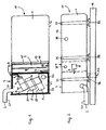
- Fig. 1
- schematisiert einen Längsschnitt durch ein erstes Ausführungsbeispiel der Erfindung,
- Fig. 2
- das erste Ausführungsbeispiel der Erfindung in Draufsicht angebaut am Fahrgestell-Rahmen eines Lastkraftwagens, und
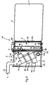
- Fig. 3
- schematisiert einen Längsschnitt durch ein zweites Ausführungsbeispiel der Erfindung.
- In der Zeichnung sind gleiche bzw. einander entsprechende Teile mit gleichen Bezugszeichen angegeben.
- Die Erfindung bezieht sich auf ein Kraftfahrzeug, insbesondere Lastkraftwagen, mit einer Brennkraftmaschine, insbesondere Dieselmotor, die aus einem Kraftstofftank 1 mit Kraftstoff versorgbar ist. Bei den dargestellten Beispielen sind im Abgasstrang 2 der Brennkraftmaschine ein Vorschalldämpfer 3 und ein Hauptschalldämpfer (nicht dargestellt) angeordnet. Der Vorschalldämpfer 3 ist dabei auf der einen Seite und der Hauptschalldämpfer auf der anderen Seite des Fahrgestell-Rahmens angeordnet und stehen über einen Abschnitt 2/2 der Abgasleitung 2 miteinander in Verbindung. In den Vorschalldämpfer 3 sind ein Hydrolysekatalysator 4 und eventuell wenigstens noch ein Oxidationskatalysator 5 eingebaut. Letztere(r) dient/dienen dazu, den NO2-Anteil im Abgas signifikant zu erhöhen. Der Hydrolysekatalysator 4 ist mittels einer Dosiereinrichtung 6 über eine Dosierleitung 7 mit Sprühkopf 8 am freien Ende mit einer Harnstoff-Wasser-Lösung (HWL) beaufschlagbar, die in einem eigenen HWL-Tank 9 bevorratbar ist. Den Vorschalldämpfer 3 verlässt demnach ein mit Ammoniak und hohem NO2-Anteil dosiertes Abgas, das mittels im Hauptschalldämpfer angeordneter SCR-Katalysatoren in optimaler Weise reinigbar ist.
- Erfindungsgemäß schließt sich der HWL-Tank 9 an einer Stirnseite des Kraftstofftanks 1 mit einem zunächst topfförmigen, nach vorne hin offenen HWL-Tank-Gehäuse 25 an, in das ein vorgefertigter HWL-Tank-Innenkörper 26 von vorne her einbaubar ist und das anschließend durch eine Frontwand 27 verschließbar ist. Dabei bildet der vorgefertigte HWL-Tank 9 mit wenigstens dem Kraftstofftank 1 eine kompakte Baueinheit 10, die in ihrer Gesamtheit am Fahrgestell-Rahmen des Fahrzeugs, dort einem der beiden Rahmen-Längsträger 11 befestigbar ist. Der HWL-Tank 9 und der Kraftstofftank 1 sind in Reihe hintereinander angeordnet. In den dargestellten Beispielen schließt sich vorne an den HWL-Tank 9 der Vorschalldämpfer 3 an, so dass der HWL-Tank 9 zwischen Vorschalldämpfer 3 und Kraftstofftank angeordnet ist. Vorzugsweise wird die aus dem Kraftstofftank 1 und HWL-Tank 9 bestehende und gegebenenfalls durch den Vorschalldämpfer 3 ergänzte Baueinheit 10 komplett vormontiert am Fahrgestellrahmen 11 anstelle eines Kraftstofftanks angebaut, dessen Baulänge oder Volumen etwa jener bzw. jenem der Baueinheit 10 entspricht. Dabei weist der innerhalb der Baueinheit 10 gegebene Kraftstofftank 1 gegenüber dem ersetzten Kraftstofftank bei gleichem Querschnitt ein z. B. um 30 bis 40 % kleineres Tankvolumen auf. Dieser solchermaßen gewonnene Bauraum teilt sich teils, beispielsweise zu etwa 1/3 auf den HWL-Tank 9 und teils, beispielsweise zu etwa 2/3 auf den Vorschalldämpfer 3 auf. Es können sich fallweise aber auch andere als vorgenannte Aufteilungen als praktikabel bzw. notwendig erweisen.
- In Beispiel gemäß
Fig. 1 ist der Kraftstofftank 1 innerhalb eines Gehäuses 12 durch eine Doppelwand 13, 14 vom HWL-Tank 9 getrennt, so dass bei etwaigen HWL-Leckagen diese nicht in den Kraftstofftank 1 gelangen können. Der HWL-Tank 9 weist innen generell eine thermisch isolierende Auskleidung 15 sowie eine in ihn eingebaute Heizeinrichtung 16, die ein Einfrieren der HWL verhindert, und einen in ihn eingebauten Füllstandsensor 17 auf. Die HWL-Dosiereinrichtung 6 ist im Bereich des HWL-Tanks 9, dort vorzugsweise oben angebaut, angeordnet. Von dieser HWL-Dosiereinrichtung 6 ragt ein vertikales HWL-Saugrohr 18 in den HWL-Tank 9 hinein und reicht dort bis nahe zu dessen Boden hinunter. Außerdem geht von dieser Dosiereinrichtung 6 seitlich die HWL-Dosierleitung 7 ab, die in den Innenraum des Vorschalldämpfers 3 hineingeführt ist und dort im Eingangsbereich des Hydrolysekatalysators 4 bzw. dessen Gehäuses 4/1 mit ihrem Sprühkopf 8 endet. - Der Innenraum des Vorschalldämpfers 3 ist in den dargestellten Beispielen durch eine Zwischenwand 19 in eine Einströmkammer 20 und eine Ausströmkammer 21 unterteilt, wobei die Einströmkammer 20 mit einem von der Brennkraftmaschine bzw. deren Aufladeaggregat kommenden Abschnitt 2/1 der Abgasleitung 2 und die Ausströmkammer 21 mit einem die Verbindung zum Hauptschalldämpfer herstellenden Abschnitt 2/2 der Abgasleitung 2 kommuniziert. Die Katalysatoren 4, 5 sind im Vorschalldämpfer 3 achsparallel zueinander und nebeneinander angeordnet und dort mit ihren Gehäusen 4/1 bzw. 5/1 in der Zwischenwand 19 sowie einer beabstandet an dieser angeordneten Haltewand 22 befestigt. Die gezeigte Schrägstellung der Katalysatoren 4, 5 ist eine mögliche Einbauart. Wenn es der Bauraum des Vorschalldämpfers 3 und die Größe der Katalysatoren 4, 5 zulassen, sind letztere auch anders, z. B. vertikal stehend parallel zueinander und nebeneinander in den Vorschalldämpfer 3 einbaubar.
- Der Vorschalldämpfer 3 ist innen mit einer Schicht 23 aus schalldämmenden Material ausgekleidet und zum HWL-Tank 9 hin noch zusätzlich thermisch isoliert, um eine zu starke Wärmeübertragung von dem den Vorschalldämpfer 3 durchströmenden Abgas zum HWL-Tank 9 hin zu vermeiden.
- Beim Ausführungsbeispiel gemäß
Fig. 3 ist der Kraftstofftank 1 durch einen vorgefertigten Behälter aus Stahl oder Aluminium oder aluminiertem Stahlblech mit allseitig geschlossener Behälterwand 1' gebildet. An der vorderen Stirnwand 24 dieses Kraftstofftanks 1 wird ein topfförmiges, nach vorne zum Vorschalldämpfer 3 hin zunächst offenes HWL-Tank-Gehäuse 25 angeschlossen, vorzugsweise angeschweißt. In dieses wird dann ein in sich geschlossener, aus einem dickwandigen Isolationsmaterial vorgefertigter HWL-Tank-Innenkörper 26 von vorne her eingebaut. Das HWL-Tank-Gehäuse 25 ist anschließend durch eine HWL-Tank-Frontwand 27 verschließbar. Diese bildet bei diesem Beispiel gleichzeitig eine Zwischenwand zwischen HWL-Tank 9 und Vorschalldämpfer 3 und ist auf ihrer dem Innenraum des Vorschalldämpfers 3 zugewandten Seite mit einer Schicht 28 aus thermisch isolierendem Material beschichtet. An diese HWL-Tank-Frontwand 27 schließt sich eine zylindrische Umfangsaußenwand 29 des Vorschalldämpfers 3 an. Die mechanische Verbindung erfolgt z. B. durch Umbördelung der Umfangsaußenwand 29 im Bereich der HWL-Tank-Frontwand 27 einschließlich des ebenen vorderen Randes 30 am HWL-Tank-Gehäuse 25, an den sich die HWL-Tank-Frontwand 27 abstützt. Stirnseitig an der Umfangsaußenwand 29 schließt sich die vordere Stirnwand 31 des Vorschalldämpfers 3 an und ist mit letzterer z. B. durch randseitige Umbördelung verbindbar. - Innerhalb des Ausführungsbeispiels gemäß
Fig. 3 bilden die Zwischenwand 19, die Haltewand 22 und die in ihren Gehäusen 4/1, 5/1 aufgenommenen Katalysatoren 4, 5 eine vorzufertigende Baugruppe, an deren Zwischenwand 19 anschließend die vordere Stirnwand 31 durch Anschweißen befestigbar ist. Danach werden an der vorderen Stirnwand 31 die Schicht 23 aus Isoliermaterial und dann die Umfangsaußenwand 29 angebracht, letztere z. B. durch randseitige Umbördelung. Anschließend wird die Zwischenwand 19 mit der Umfangsaußenwand 29 durch Schweißen verbunden. Die Umfangsaußenwand 29 ist vorher ebenfalls mit der Isoliermaterialschicht 23 belegt worden, zumindest in den Bereichen, die nach dem Anschweißen der Zwischenwand 19 nicht mehr zugänglich sind. Im nächsten Arbeitsgang wird ein Dosierleitungsstück 7/1 in eine Öffnung in der Umfangsaußenwand 29 eingesetzt und dort befestigt. Zuletzt wird diese solchermaßen vorgefertigte Vorschalldämpfer-Baugruppe zusammen mit der schon mit Thermoisolierschicht 28 und Schalldämmungsmaterial 23 beschichteten HWL-Tank-Frontwand 27 am vorderen Rand 30 des HWL-Tank-Gehäuses 25 angesetzt und zuletzt durch randseitige Umbördelung der Umfangsaußenwand 29 am HWL-Tank-Gehäuse 25 befestigt. Dann kann die Dosiereinrichtung 6 und das Leitungsverbindungsstück der Dosierleitung zum Teilstück 7/1 montiert werden. - Es versteht sich von selbst, dass im Rahmen des allgemeinen Erfindungsgedankens jederzeit auch andere als vorbeschriebene und in der Zeichnung dargestellte Ausführungs- und Realisierungsformen der Baueinheit 10 möglich sind.
- Eine vorgefertigte und vormontierte Baueinheit 10 wird bei ihrer Endmontage am Rahmen, dort einem Rahmen-Längsträger 11 des Fahrzeugs z. B. an rahmenfesten Konsolen 32 angesetzt und dort durch Bänder, Bügel oder dergleichen Organe 33 befestigt.
- Im Betrieb ist der Kraftstofftank 1 über einen durch einen Tankdeckel 34 verschließbaren Einfüllstutzen mit Kraftstoff und der HWL-Tank 9 über einen relativ weit davon entfernten, durch einen Tankdeckel 35 verschließbaren Einfüllstutzen mit HWL befüllbar.
Claims (10)
- Kraftfahrzeug, insbesondere Lastkraftwagen, mit einer Brennkraftmaschine, die aus einem Kraftstofftank (1) mit Kraftstoff versorgbar ist und in deren Abgasstrang (2) ein Hydrolysekatalysator (4), wenigstens ein weiterer Katalysator (5) und wenigstens ein Schalldämpfer (3) angeordnet sind, wobei der Hydrolysekatalysator (4) mittels einer Dosiereinrichtung (6, 7) mit einer in einem HWL-Tank (9) bevorrateten Harnstoff-Wasser-Lösung (HWL) beaufschlagbar ist, dadurch gekennzeichnet, dass sich der HWL-Tank (9) an einer Stirnseite des Kraftstofftanks (1) mit einem zunächst topfförmigen, nach vorne hin offenen HWL-Tank-Gehäuse (25) anschließt, in das ein vorgefertigter HWL-Tank-Innenkörper (26) von vorne her einbaubar ist und das anschließend durch eine Frontwand (27) verschließbar ist.
- Kraftfahrzeug nach Anspruch 1, dadurch gekennzeichnet, dass eine kompakte, wenigstens aus dem Kraftstofftank (1) und dem fertigen HWL-Tank (9) bestehende, komplett vormontierte Baueinheit (10) am Fahrgestell-Rahmen (11) anstelle eines Kraftstofftanks anbaubar ist, dessen Baulänge oder Volumen etwa jener bzw. jenem der Baueinheit (10) entspricht, wobei innerhalb der Baueinheit (10) der Kraftstofftank (1) gegenüber dem ersetzten Kraftstofftank bei gleichem Querschnitt ein kleineres Tankvolumen aufweist, in welchem solchermaßen gewonnenen Bauraum der HWL-Tank (9) angeordnet ist.
- Kraftfahrzeug nach Anspruch 1, dadurch gekennzeichnet, dass der HWL-Tank (9) - in Fahrtrichtung vorwärts gesehen - in Reihe mit und vor dem Kraftstofftank (1) angeordnet ist.
- Kraftfahrzeug nach Anspruch 1, dadurch gekennzeichnet, dass zwischen Kraftstofftank (1) und HWL-Tank (9) eine Doppelwand angeordnet ist, die bei etwaigen Tankleckagen das Vordringen des Leckagemediums in den anderen Tankbereich verhindert.
- Kraftfahrzeug nach Anspruch 1, gekennzeichnet durch einen aus einem dickwandigen Isolationsmaterial vorgefertigten HWL-Tank-Innenkörper (26).
- Kraftfahrzeug nach Anspruch 1, dadurch gekennzeichnet, dass nach Einbau des HWL-Tank-Innenkörpers (26) in das HWL-Tank-Gehäuse (25) an dessen vorderem Rand die HWL-Tank-Frontwand (27) ansetzbar und durch randseitige Umbördelung der Umfangsaußenwand (29) am HWL-Tank-Gehäuse (25) befestigbar ist.
- Kraftfahrzeug nach Anspruch 1, dadurch gekennzeichnet, dass der HWL-Tank (9) eine ihn thermisch isolierende Auskleidung (15) aufweist.
- Kraftfahrzeug nach Anspruch 1, dadurch gekennzeichnet, dass in den HWL-Tank (9) eine Heizeinrichtung (16) eingebaut ist.
- Kraftfahrzeug nach Anspruch 1, dadurch gekennzeichnet, dass in den HWL-Tank (9) ein Füllstandssensor (17) eingebaut ist.
- Kraftfahrzeuge nach Anspruch 1, dadurch gekennzeichnet, dass die HWL-Dosiereinrichtung (6) im Bereich des HWL-Tanks (9) angeordnet ist, dass von dieser HWL-Dosiereinrichtung (6) ein vertikales HWL-Saugrohr (18) in den HWL-Tank (9) hineinragt und bis nahe zu dessen Boden hinunter reicht und dass eine HWL-Dosierfeitung (7) von der Dosiereinrichtung (6) abgeht, die im Eingangsbereich des Hydrolysekatalysators (4) bzw. dessen Gehäuses (4/1) mit einem Sprühkopf (8) endet.
Priority Applications (1)
| Application Number | Priority Date | Filing Date | Title |
|---|---|---|---|
| PL05008020T PL1553271T3 (pl) | 2003-08-01 | 2004-07-10 | Pojazd ze specjalnym układem zbiornika paliwa i zbiornika środka redukującego |
Applications Claiming Priority (3)
| Application Number | Priority Date | Filing Date | Title |
|---|---|---|---|
| DE10335265.1A DE10335265B4 (de) | 2003-08-01 | 2003-08-01 | Kraftfahrzeug mit spezieller Anordnung eines Kraftstofftanks, Vorschalldämpfers und Reduktionsmitteltanks |
| DE10335265 | 2003-08-01 | ||
| EP04016280A EP1503055B1 (de) | 2003-08-01 | 2004-07-10 | Kraftfahrzeug mit spezieller Anordnung eines Kraftstofftanks, Vorschalldämpfers und Reduktionsmitteltanks |
Related Parent Applications (2)
| Application Number | Title | Priority Date | Filing Date |
|---|---|---|---|
| EP04016280.2 Division | 2004-07-10 | ||
| EP04016280A Division EP1503055B1 (de) | 2003-08-01 | 2004-07-10 | Kraftfahrzeug mit spezieller Anordnung eines Kraftstofftanks, Vorschalldämpfers und Reduktionsmitteltanks |
Publications (3)
| Publication Number | Publication Date |
|---|---|
| EP1553271A2 EP1553271A2 (de) | 2005-07-13 |
| EP1553271A3 EP1553271A3 (de) | 2007-08-29 |
| EP1553271B1 true EP1553271B1 (de) | 2008-05-07 |
Family
ID=33521524
Family Applications (2)
| Application Number | Title | Priority Date | Filing Date |
|---|---|---|---|
| EP05008020A Expired - Lifetime EP1553271B1 (de) | 2003-08-01 | 2004-07-10 | Kraftfahrzeug mit spezieller Anordnung eines Kraftstofftanks und Reduktionsmitteltanks |
| EP04016280A Expired - Lifetime EP1503055B1 (de) | 2003-08-01 | 2004-07-10 | Kraftfahrzeug mit spezieller Anordnung eines Kraftstofftanks, Vorschalldämpfers und Reduktionsmitteltanks |
Family Applications After (1)
| Application Number | Title | Priority Date | Filing Date |
|---|---|---|---|
| EP04016280A Expired - Lifetime EP1503055B1 (de) | 2003-08-01 | 2004-07-10 | Kraftfahrzeug mit spezieller Anordnung eines Kraftstofftanks, Vorschalldämpfers und Reduktionsmitteltanks |
Country Status (8)
| Country | Link |
|---|---|
| US (1) | US7017336B2 (de) |
| EP (2) | EP1553271B1 (de) |
| JP (1) | JP4460970B2 (de) |
| KR (1) | KR101036574B1 (de) |
| CN (1) | CN1311998C (de) |
| DE (2) | DE10335265B4 (de) |
| PL (2) | PL1503055T3 (de) |
| RU (1) | RU2270105C1 (de) |
Families Citing this family (68)
| Publication number | Priority date | Publication date | Assignee | Title |
|---|---|---|---|---|
| DE10357120B4 (de) * | 2003-12-06 | 2006-06-01 | Daimlerchrysler Ag | Kraftfahrzeug mit Abgasreinigungsanlage und Betriebsverfahren hierfür sowie Abgasreinigungsanlage für ein Kraftfahrzeug |
| JP2005226528A (ja) * | 2004-02-12 | 2005-08-25 | Tokyo Roki Co Ltd | Scrマフラー |
| FR2875748B1 (fr) * | 2004-09-27 | 2006-12-08 | Inergy Automotive Systems Res | Methode de remplissage d'un reservoir au moyen d'une cartouche-reservoir et cartouche associes |
| JP3715985B1 (ja) * | 2004-10-29 | 2005-11-16 | 日産ディーゼル工業株式会社 | 液体還元剤噴射ノズル構造 |
| AT500745B8 (de) * | 2005-02-02 | 2007-02-15 | Pankl Emission Control Systems | Abgasreinigungsvorrichtung |
| DE102005029415A1 (de) * | 2005-06-24 | 2006-12-28 | Man Nutzfahrzeuge Ag | Kraftfahrzeug mit einem Reduktionsmittelraum für eine Abgasreinigungsanlage |
| DE102005032823A1 (de) | 2005-07-12 | 2007-01-18 | Eichenauer Heizelemente Gmbh & Co. Kg | Tankheizung |
| DE102005056396B4 (de) * | 2005-11-24 | 2021-05-12 | MAGNA Energy Storage Systems GmbH Werk Schwäbisch Gmünd | Kraftstoffbehälter |
| JP4711809B2 (ja) * | 2005-11-28 | 2011-06-29 | 京セラ株式会社 | 通信方法、移動端末及び基地局 |
| US8056322B2 (en) * | 2005-12-12 | 2011-11-15 | General Electric Company | System and method for supplying oxygenate reductants to an emission treatment system |
| US7487631B2 (en) * | 2005-12-12 | 2009-02-10 | General Electric Company | System and method for supplying reductants to an emission treatment system |
| US20090127265A1 (en) * | 2006-04-27 | 2009-05-21 | Volvo Lastvagnar Ab | Liquid receptacle for a vehicle |
| US20070265895A1 (en) * | 2006-05-09 | 2007-11-15 | Sap Ag | Ad-hoc workflow as a business process template |
| DE102006048721B4 (de) | 2006-10-16 | 2018-04-19 | Robert Bosch Gmbh | Katalytische Reduktionseinrichtung für eine katalytische Reduktion von Stickoxiden in Abgasanlagen |
| DE102007012948A1 (de) * | 2007-03-14 | 2008-09-18 | Erhard & Söhne GmbH | Kraftstoffbehälter |
| US8230678B2 (en) * | 2007-06-21 | 2012-07-31 | Daimler Trucks North America Llc | Treatment of diesel engine exhaust |
| US8069655B2 (en) * | 2007-08-13 | 2011-12-06 | Cummins Filtration Ip, Inc. | Apparatus, system, and method for using a fraction of engine exhaust to deliver a dosant |
| US8096112B2 (en) * | 2007-09-28 | 2012-01-17 | Caterpillar Inc. | Exhaust after-treatment system having a secondary tank |
| JP4826612B2 (ja) * | 2007-10-12 | 2011-11-30 | マツダ株式会社 | 車両の排気浄化装置配設構造 |
| US8056671B2 (en) * | 2007-10-12 | 2011-11-15 | Mazda Motor Corporation | Exhaust-gas purification device disposition structure of vehicle |
| EP2065578A1 (de) | 2007-11-28 | 2009-06-03 | International Engine Intellectual Property | Heizsystem für in einem Abgasreinigungssystem verwendete Reagenzen |
| US7987663B2 (en) * | 2007-11-30 | 2011-08-02 | General Electric Company | Methods for reducing emissions from diesel engines |
| US20090173058A1 (en) * | 2008-01-09 | 2009-07-09 | General Electric Company | System and method for the on-board production of reductants |
| US20090173061A1 (en) * | 2008-01-09 | 2009-07-09 | General Electric Company | OPTIMIZED REDUCTION OF NOx EMISSIONS FROM DIESEL ENGINES |
| GB0807173D0 (en) * | 2008-04-19 | 2008-05-21 | Agco Gmbh | Exhaust gas treatment system |
| US20090282813A1 (en) * | 2008-05-17 | 2009-11-19 | The Itb Group Ltd. | Thermal Stability for Exhaust Emissions Treatment Materials |
| US8201398B2 (en) * | 2008-05-30 | 2012-06-19 | Daimler Trucks North America Llc | Diesel engine exhaust treatment system with drive shaft accommodating housing and method |
| DE102008035268A1 (de) | 2008-07-29 | 2010-03-25 | Mykhaylo Koltun | Verfahren zur katalytischen Verarbeitung von Flüssigkeiten und Gasen |
| DE102008035271B4 (de) | 2008-07-29 | 2023-06-29 | Genady Maslov | Verfahren und Einrichtung zur Verarbeitung von Abgasen (Dieselmotor) |
| DE202008010122U1 (de) | 2008-07-29 | 2009-05-14 | Koltun, Mykhaylo | Einrichtung zur Durchführung des Abgasreinigungsverfahrens (Ottomotor) |
| DE202008010119U1 (de) | 2008-07-29 | 2009-05-07 | Koltun, Mykhaylo | Einrichtung zur Reinigung von Abgasen der Turbostrahltriebwerke |
| DE202008010121U1 (de) | 2008-07-29 | 2009-05-14 | Koltun, Mykhaylo | Einrichtung zur Durchführung des Abgasreinigungsverfahrens (Dieselmotor) |
| DE102008035270B4 (de) | 2008-07-29 | 2023-08-03 | Mykhaylo Koltun | Verfahren und Einrichtung zur Verarbeitung von Abgasen (Ottomotor) |
| US8206656B2 (en) * | 2008-07-30 | 2012-06-26 | Ford Global Technologies, Llc | Freezable-liquid dispenser for motor vehicles |
| US8359831B2 (en) | 2008-10-31 | 2013-01-29 | Ti Group Automotive Systems, L.L.C. | Reactant delivery for engine exhaust gas treatment |
| DE102008057521A1 (de) | 2008-11-15 | 2010-05-20 | Daimler Ag | Tankbehälter für ein Kraftfahrzeug |
| DE102009000094A1 (de) * | 2009-01-09 | 2010-07-15 | Robert Bosch Gmbh | Tank zur Aufnahme einer wässrigen Lösung |
| US20100186394A1 (en) * | 2009-01-26 | 2010-07-29 | Caterpillar Inc. | Exhaust gas after treatment assembly |
| KR101131419B1 (ko) * | 2009-12-23 | 2012-04-03 | 한국철도기술연구원 | 저상 버스용 배기장치 |
| JP5372727B2 (ja) * | 2009-12-24 | 2013-12-18 | いすゞ自動車株式会社 | 還元剤タンクの固定構造 |
| DE102010004612A1 (de) * | 2010-01-13 | 2011-07-14 | Emitec Gesellschaft für Emissionstechnologie mbH, 53797 | Vorrichtung mit einem Tank und einer Fördereinheit für Reduktionsmittel |
| US9879829B2 (en) | 2010-06-15 | 2018-01-30 | Shaw Development, Llc | Tank module interface for fluid reservoirs |
| DE102010035008A1 (de) * | 2010-08-20 | 2012-02-23 | Emitec Gesellschaft Für Emissionstechnologie Mbh | Harnstoffbehälter mit Ultraschallsensor |
| US8822887B2 (en) | 2010-10-27 | 2014-09-02 | Shaw Arrow Development, LLC | Multi-mode heater for a diesel emission fluid tank |
| KR101367024B1 (ko) * | 2012-06-28 | 2014-02-24 | 두산엔진주식회사 | 보조 발전용 연료 전지를 이용한 우레아 가수분해 장치 및 이를 구비한 선택적 촉매 환원 시스템 |
| DE102012112666B3 (de) * | 2012-12-19 | 2014-03-27 | Elkamet Kunststofftechnik Gmbh | Abdeckung mit Einfüllstutzen |
| ITVR20120252A1 (it) * | 2012-12-28 | 2014-06-29 | Piusi Spa | Apparecchiatura per il rifornimento di liquidi additivi antinquinamento per veicoli a motore diesel. |
| FR3003533B1 (fr) * | 2013-03-25 | 2015-04-24 | Peugeot Citroen Automobiles Sa | Ensemble pour chassis comportant un reservoir de stockage d'un agent de depollution et vehicule automobile correspondant |
| DE102013105884A1 (de) * | 2013-06-07 | 2014-12-11 | Claas Tractor S.A.S. | Landwirtschaftliches Fahrzeug, Speichereinrichtung sowie Verfahren zur Herstellung derselben |
| KR101336118B1 (ko) * | 2013-06-21 | 2013-12-03 | 우신산업(주) | 상용차용 일체형탱크 |
| WO2015045106A1 (ja) * | 2013-09-27 | 2015-04-02 | 株式会社小松製作所 | 作業車両 |
| DE102013019448A1 (de) * | 2013-11-21 | 2015-06-03 | Wirtgen Gmbh | Selbstfahrende Baumaschine |
| CN104196602A (zh) * | 2014-03-06 | 2014-12-10 | 万向通达股份公司 | 车辆排放后处理器总成 |
| DE102014007858A1 (de) * | 2014-05-24 | 2015-11-26 | Man Diesel & Turbo Se | Abgasnachbehandlungsvorrichtung |
| USD729722S1 (en) | 2014-05-28 | 2015-05-19 | Shaw Development LLC | Diesel emissions fluid tank floor |
| USD729141S1 (en) | 2014-05-28 | 2015-05-12 | Shaw Development LLC | Diesel emissions fluid tank |
| CN104047687A (zh) * | 2014-07-03 | 2014-09-17 | 中国重汽集团济南动力有限公司 | 一种重型车用催化转化装置 |
| KR101567229B1 (ko) | 2014-07-07 | 2015-11-09 | 현대자동차주식회사 | 요소수 오버플로우 방지타입 요소수 필러 넥 및 요소수 탱크, 실외형 필러넥을 갖춘 요소수 후처리 시스템 |
| US9650932B2 (en) | 2014-12-22 | 2017-05-16 | Caterpillar Inc. | Insulated reductant tank |
| JP6689044B2 (ja) * | 2015-08-18 | 2020-04-28 | 株式会社竹内製作所 | 作業用車両 |
| KR102237197B1 (ko) | 2015-12-14 | 2021-04-06 | 현대자동차주식회사 | 연료탱크와 일체화된 우레아탱크 및 그 제조방법 |
| SE539834C2 (en) * | 2016-04-11 | 2017-12-12 | Scania Cv Ab | An injection arrangement for injection of a urea solution into an exhaust gas passage |
| WO2018229214A1 (en) * | 2017-06-16 | 2018-12-20 | Umicore Ag & Co. Kg | Combined soot filter and urea hydrolysis |
| JP7149726B2 (ja) * | 2018-04-20 | 2022-10-07 | 末吉工業株式会社 | 車両用複合タンク |
| CN110871676A (zh) * | 2018-08-30 | 2020-03-10 | 彭宏伟 | 一种油箱及其托架 |
| US20210122235A1 (en) * | 2019-10-23 | 2021-04-29 | Mayville Engineering Company Inc. | Diesel exhaust fluid tank |
| GB202020251D0 (en) | 2020-12-21 | 2021-02-03 | Agco Int Gmbh | Container system |
| US20230044506A1 (en) * | 2021-08-06 | 2023-02-09 | Anthony Kelly | Fuel/diesel exhaust fluid combination auxiliary tank |
Family Cites Families (19)
| Publication number | Priority date | Publication date | Assignee | Title |
|---|---|---|---|---|
| DE3501094A1 (de) * | 1984-09-25 | 1986-07-17 | Lothar 4175 Wachtendonk Kehne | Doppelrohr-katalysator fuer verbrennungsmotoren |
| US4852761A (en) * | 1988-07-25 | 1989-08-01 | General Motors Corporation | In tank vapor storage canister |
| DE4018197C2 (de) * | 1990-06-07 | 2000-10-12 | Opel Adam Ag | Kraftfahrzeug mit einem am Unterboden unterhalb des Fahrzeughecks befestigten Kraftstofftank |
| JPH08508687A (ja) * | 1993-01-21 | 1996-09-17 | ユナイテッド・テクノロジー・コーポレーション | 耐圧性燃料タンクパネル |
| DE4417237C2 (de) * | 1994-05-17 | 2001-09-13 | Siemens Ag | Lastkraftwagen |
| DE19729003C2 (de) | 1997-07-07 | 1999-05-27 | Siemens Ag | Tank für ein Fahrzeug mit reduktionsmittelbetriebener Abgas-Reinigungsanlage |
| JPH1193651A (ja) * | 1997-09-19 | 1999-04-06 | Nippon Electric Ind Co Ltd | 消音装置 |
| US6223526B1 (en) * | 1998-06-17 | 2001-05-01 | Siemens Aktiengesellschaft | Dual compartment fuel storage tank |
| KR20000012096A (ko) * | 1998-07-31 | 2000-02-25 | 칼 하인쯔 호르닝어 | 탱크를 채우는 방법 및 장치 |
| ES2191386T3 (es) * | 1998-07-31 | 2003-09-01 | Siemens Ag | Dispositivo para llenar contenedores. |
| DE10042542A1 (de) | 2000-08-30 | 2002-03-14 | Eberspaecher J Gmbh & Co | Abgasreinigungssystem für Kraftfahrzeuge, insbesondere Diesel-Nutzfahrzeuge |
| DE10063569A1 (de) * | 2000-12-20 | 2002-07-04 | Man Nutzfahrzeuge Ag | Fahrzeugbehälter |
| DE10123359A1 (de) * | 2001-05-14 | 2002-11-21 | Man Nutzfahrzeuge Ag | Abgasstrang einer Brennkraftmaschine, insbesondere Dieselmotor eines Nutzfahrzeuges wie Lastkraftwagen oder Omnibus, mit integrierten Abgasnachbehandlungs- und Schalldämpfungseinrichtungen |
| US6390147B1 (en) * | 2001-05-17 | 2002-05-21 | Ford Global Technologies, Inc. | Fuel and reductant delivery system |
| CN2490002Y (zh) * | 2001-06-27 | 2002-05-08 | 王熙平 | 内燃机废气降温消音净化装置 |
| EP1350654A1 (de) * | 2002-03-21 | 2003-10-08 | Alutech Gesellschaft m.b.H. | Fahrzeugtank |
| US6810661B2 (en) * | 2002-08-09 | 2004-11-02 | Ford Global Technologies, Llc | Method and system for freeze protecting liquid NOx reductants for vehicle application |
| US6941746B2 (en) * | 2002-11-21 | 2005-09-13 | Combustion Components Associates, Inc. | Mobile diesel selective catalytic reduction systems and methods |
| DE10339548A1 (de) * | 2003-08-26 | 2005-03-31 | Kautex Textron Gmbh & Co. Kg | Verfahren und Vorrichtung zur Kraftstoffversorgung eines wasserstoffbetriebenen Kraftfahrzeugs |
-
2003
- 2003-08-01 DE DE10335265.1A patent/DE10335265B4/de not_active Expired - Lifetime
-
2004
- 2004-07-10 PL PL04016280T patent/PL1503055T3/pl unknown
- 2004-07-10 DE DE502004007045T patent/DE502004007045D1/de not_active Expired - Lifetime
- 2004-07-10 EP EP05008020A patent/EP1553271B1/de not_active Expired - Lifetime
- 2004-07-10 PL PL05008020T patent/PL1553271T3/pl unknown
- 2004-07-10 EP EP04016280A patent/EP1503055B1/de not_active Expired - Lifetime
- 2004-07-29 JP JP2004222358A patent/JP4460970B2/ja not_active Expired - Fee Related
- 2004-07-30 RU RU2004123587/11A patent/RU2270105C1/ru active
- 2004-07-30 KR KR1020040060182A patent/KR101036574B1/ko not_active Expired - Fee Related
- 2004-07-30 US US10/903,463 patent/US7017336B2/en not_active Expired - Lifetime
- 2004-08-02 CN CNB2004100556803A patent/CN1311998C/zh not_active Expired - Lifetime
Also Published As
| Publication number | Publication date |
|---|---|
| JP4460970B2 (ja) | 2010-05-12 |
| PL1503055T3 (pl) | 2012-02-29 |
| CN1579827A (zh) | 2005-02-16 |
| KR20050016051A (ko) | 2005-02-21 |
| DE502004007045D1 (de) | 2008-06-19 |
| US7017336B2 (en) | 2006-03-28 |
| EP1503055B1 (de) | 2011-09-28 |
| DE10335265B4 (de) | 2014-02-27 |
| PL1553271T3 (pl) | 2008-09-30 |
| DE10335265A1 (de) | 2005-02-17 |
| EP1503055A1 (de) | 2005-02-02 |
| RU2270105C1 (ru) | 2006-02-20 |
| EP1553271A3 (de) | 2007-08-29 |
| US20050022515A1 (en) | 2005-02-03 |
| JP2005054788A (ja) | 2005-03-03 |
| KR101036574B1 (ko) | 2011-05-24 |
| EP1553271A2 (de) | 2005-07-13 |
| CN1311998C (zh) | 2007-04-25 |
Similar Documents
| Publication | Publication Date | Title |
|---|---|---|
| DE10335265B4 (de) | Kraftfahrzeug mit spezieller Anordnung eines Kraftstofftanks, Vorschalldämpfers und Reduktionsmitteltanks | |
| EP2718550B1 (de) | Schalldämpfer und herstellungsverfahren | |
| EP2116702B1 (de) | Tank für ein Reduktionsmittel, Kraftfahrzeug mit einem Tank für ein Reduktionsmittel sowie ein Verfahren zum Betrieb einer SCR-Anlage eines Kraftfahrzeuges | |
| DE112012003803B4 (de) | Reduktionsmittelzufuhreinheit für eine selektive katalytische Reduktions-(SCR)Nachbehandlung von Abgasen für Fahrzeuge mit einer Aufnahmestruktur für eine gefrorene Komponente | |
| WO2008107151A1 (de) | Abgasnachbehandlungseinrichtung eines kraftfahrzeugs | |
| DE102010052937A1 (de) | Abgaseinrichtung für Quermotor | |
| WO2012113500A1 (de) | Kraftfahrzeug | |
| DE102008056350B4 (de) | Schalldämpfer und zugehöriges Herstellungsverfahren | |
| EP3025939B1 (de) | Zugmaschine mit zwei seitlichen windabweisern und dazwischenliegendem fluidtank | |
| WO2006045672A1 (de) | Tankmodul für ein reduktionsmittel und dosiersystem | |
| DE102014110880A1 (de) | Harnstofflösung-Vorrichtung für Fahrzeuge | |
| DE102010052938B4 (de) | Abgaseinrichtung für Quermotor | |
| DE102010021301A1 (de) | Kraftfahrzeug mit einem Kraftstofftank und einem Zusatztank | |
| EP1562819B1 (de) | Vorderwagenstruktur | |
| DE102013105884A1 (de) | Landwirtschaftliches Fahrzeug, Speichereinrichtung sowie Verfahren zur Herstellung derselben | |
| DE202006013535U1 (de) | Behälter für Fluide | |
| WO2013079509A1 (de) | Abgasnachbehandlungssystem und verfahren zum einbringen eines reduktionsmittels in einen abgaskanal einer brennkraftmaschine | |
| EP0911510B1 (de) | Brennkraftmaschine mit einer Abgasrückführ-Vorrichtung, insbesondere Diesel-Brennkraftmaschine | |
| EP1852583B1 (de) | Abgasanlage einer Brennkraftmaschine mit mehreren Katalysatoren im Abgasstrang | |
| EP1862651A2 (de) | Isoliervorrichtung für ein, insbesondere von einem heißen Medium durchströmbares Maschinenelement | |
| EP1172534A2 (de) | Abgaskrümmer | |
| EP1510674A1 (de) | Abgasstrang einer Brennkraftmaschine mit eingebautem Vor- und Hauptschalldämpfer | |
| DE102008057521A1 (de) | Tankbehälter für ein Kraftfahrzeug | |
| DE4417237C2 (de) | Lastkraftwagen | |
| DE102013225256A1 (de) | Fahrzeug |
Legal Events
| Date | Code | Title | Description |
|---|---|---|---|
| PUAI | Public reference made under article 153(3) epc to a published international application that has entered the european phase |
Free format text: ORIGINAL CODE: 0009012 |
|
| AC | Divisional application: reference to earlier application |
Ref document number: 1503055 Country of ref document: EP Kind code of ref document: P |
|
| AK | Designated contracting states |
Kind code of ref document: A2 Designated state(s): AT BE BG CH CY CZ DE DK EE ES FI FR GB GR HU IE IT LI LU MC NL PL PT RO SE SI SK TR |
|
| AX | Request for extension of the european patent |
Extension state: AL HR LT LV MK |
|
| PUAL | Search report despatched |
Free format text: ORIGINAL CODE: 0009013 |
|
| AK | Designated contracting states |
Kind code of ref document: A3 Designated state(s): AT BE BG CH CY CZ DE DK EE ES FI FR GB GR HU IE IT LI LU MC NL PL PT RO SE SI SK TR |
|
| AX | Request for extension of the european patent |
Extension state: AL HR LT LV MK |
|
| 17P | Request for examination filed |
Effective date: 20070804 |
|
| GRAP | Despatch of communication of intention to grant a patent |
Free format text: ORIGINAL CODE: EPIDOSNIGR1 |
|
| GRAS | Grant fee paid |
Free format text: ORIGINAL CODE: EPIDOSNIGR3 |
|
| GRAA | (expected) grant |
Free format text: ORIGINAL CODE: 0009210 |
|
| AC | Divisional application: reference to earlier application |
Ref document number: 1503055 Country of ref document: EP Kind code of ref document: P |
|
| AK | Designated contracting states |
Kind code of ref document: B1 Designated state(s): DE FR IT PL TR |
|
| AKX | Designation fees paid |
Designated state(s): DE FR IT PL TR |
|
| REF | Corresponds to: |
Ref document number: 502004007045 Country of ref document: DE Date of ref document: 20080619 Kind code of ref document: P |
|
| REG | Reference to a national code |
Ref country code: PL Ref legal event code: T3 |
|
| PLBE | No opposition filed within time limit |
Free format text: ORIGINAL CODE: 0009261 |
|
| STAA | Information on the status of an ep patent application or granted ep patent |
Free format text: STATUS: NO OPPOSITION FILED WITHIN TIME LIMIT |
|
| 26N | No opposition filed |
Effective date: 20090210 |
|
| REG | Reference to a national code |
Ref country code: FR Ref legal event code: CD |
|
| REG | Reference to a national code |
Ref country code: DE Ref legal event code: R081 Ref document number: 502004007045 Country of ref document: DE Owner name: MAN TRUCK & BUS AG, DE Free format text: FORMER OWNER: MAN NUTZFAHRZEUGE AG, 80995 MUENCHEN, DE Effective date: 20110518 |
|
| REG | Reference to a national code |
Ref country code: FR Ref legal event code: PLFP Year of fee payment: 13 |
|
| REG | Reference to a national code |
Ref country code: FR Ref legal event code: PLFP Year of fee payment: 14 |
|
| REG | Reference to a national code |
Ref country code: FR Ref legal event code: PLFP Year of fee payment: 15 |
|
| REG | Reference to a national code |
Ref country code: DE Ref legal event code: R081 Ref document number: 502004007045 Country of ref document: DE Owner name: MAN TRUCK & BUS SE, DE Free format text: FORMER OWNER: MAN TRUCK & BUS AG, 80995 MUENCHEN, DE |
|
| PGFP | Annual fee paid to national office [announced via postgrant information from national office to epo] |
Ref country code: TR Payment date: 20230626 Year of fee payment: 20 Ref country code: PL Payment date: 20230628 Year of fee payment: 20 |
|
| PGFP | Annual fee paid to national office [announced via postgrant information from national office to epo] |
Ref country code: IT Payment date: 20230721 Year of fee payment: 20 |
|
| PGFP | Annual fee paid to national office [announced via postgrant information from national office to epo] |
Ref country code: FR Payment date: 20230725 Year of fee payment: 20 Ref country code: DE Payment date: 20230726 Year of fee payment: 20 |
|
| REG | Reference to a national code |
Ref country code: DE Ref legal event code: R071 Ref document number: 502004007045 Country of ref document: DE |