EP1553014A1 - Boíte de bagage pour véhicule du type scooter - Google Patents
Boíte de bagage pour véhicule du type scooter Download PDFInfo
- Publication number
- EP1553014A1 EP1553014A1 EP05008260A EP05008260A EP1553014A1 EP 1553014 A1 EP1553014 A1 EP 1553014A1 EP 05008260 A EP05008260 A EP 05008260A EP 05008260 A EP05008260 A EP 05008260A EP 1553014 A1 EP1553014 A1 EP 1553014A1
- Authority
- EP
- European Patent Office
- Prior art keywords
- seat
- section
- accommodation box
- vehicle body
- pillion
- Prior art date
- Legal status (The legal status is an assumption and is not a legal conclusion. Google has not performed a legal analysis and makes no representation as to the accuracy of the status listed.)
- Granted
Links
- 230000004308 accommodation Effects 0.000 claims abstract description 50
- 230000005540 biological transmission Effects 0.000 claims description 10
- 239000002828 fuel tank Substances 0.000 description 7
- 230000007423 decrease Effects 0.000 description 2
- 230000007547 defect Effects 0.000 description 2
- 230000005484 gravity Effects 0.000 description 2
- 239000006096 absorbing agent Substances 0.000 description 1
- 238000001816 cooling Methods 0.000 description 1
- 239000000446 fuel Substances 0.000 description 1
- 230000004048 modification Effects 0.000 description 1
- 238000012986 modification Methods 0.000 description 1
- 230000035939 shock Effects 0.000 description 1
- 229920003002 synthetic resin Polymers 0.000 description 1
- 239000000057 synthetic resin Substances 0.000 description 1
- XLYOFNOQVPJJNP-UHFFFAOYSA-N water Substances O XLYOFNOQVPJJNP-UHFFFAOYSA-N 0.000 description 1
Images

Classifications
-
- B—PERFORMING OPERATIONS; TRANSPORTING
- B62—LAND VEHICLES FOR TRAVELLING OTHERWISE THAN ON RAILS
- B62K—CYCLES; CYCLE FRAMES; CYCLE STEERING DEVICES; RIDER-OPERATED TERMINAL CONTROLS SPECIALLY ADAPTED FOR CYCLES; CYCLE AXLE SUSPENSIONS; CYCLE SIDE-CARS, FORECARS, OR THE LIKE
- B62K19/00—Cycle frames
- B62K19/46—Luggage carriers forming part of frame
-
- F—MECHANICAL ENGINEERING; LIGHTING; HEATING; WEAPONS; BLASTING
- F02—COMBUSTION ENGINES; HOT-GAS OR COMBUSTION-PRODUCT ENGINE PLANTS
- F02B—INTERNAL-COMBUSTION PISTON ENGINES; COMBUSTION ENGINES IN GENERAL
- F02B61/00—Adaptations of engines for driving vehicles or for driving propellers; Combinations of engines with gearing
- F02B61/02—Adaptations of engines for driving vehicles or for driving propellers; Combinations of engines with gearing for driving cycles
-
- B—PERFORMING OPERATIONS; TRANSPORTING
- B62—LAND VEHICLES FOR TRAVELLING OTHERWISE THAN ON RAILS
- B62K—CYCLES; CYCLE FRAMES; CYCLE STEERING DEVICES; RIDER-OPERATED TERMINAL CONTROLS SPECIALLY ADAPTED FOR CYCLES; CYCLE AXLE SUSPENSIONS; CYCLE SIDE-CARS, FORECARS, OR THE LIKE
- B62K2202/00—Motorised scooters
Definitions
- the present invention relates to a scooter-type vehicle particularly provided with an improved structure of an article accommodation box.
- a scooter type vehicle such as motorcycle (two-wheeled motorcycle) generally has an article accommodation box or chamber for accommodating an article such as helmet or the like, and the accommodation box is arranged below a rider's seat. Further, in a large-size scooter type vehicle, the article accommodation box has a large inner volume so that two helmets can be accommodated therein.
- the article accommodation box is arranged in a central portion of the vehicle body (for example, as disclosed in Japanese Utility Model Laid-open Publication Nos. SHO 63-170391, SHO 63-184190 and HEI 1-73092 and Japanese Patent Laid-open Publication No. HEI 2-88376).
- the arrangement of the entire engine unit to the front side portion of the vehicle body allows the front wheel and the rear wheel to carry substantially equal loads to each other, and a weight below the spring of the rear wheel can be reduced. Accordingly, the adjusting alignment of the vehicle can be improved.
- the engine is arranged near the central portion of the vehicle body, it is difficult to secure an inner volume of the article accommodation box in which two helmets, particularly, of two full-faced helmets, are accommodated.
- An object of the present invention is to substantially eliminate defects or undesirable matters encountered in the prior art mentioned above and to provide an article accommodation box of a scooter type vehicle such as motorcycle having an improved structure which can accommodate two full-faced helmets in a longitudinal direction of a vehicle body without increasing a size thereof.
- an article accommodation box of a scooter type vehicle in which a seat member is arranged above a rear wheel so as to extend in a longitudinal direction along an advancing direction of the vehicle, the seat member includes a drive's seat section and a pillion section divided along the longitudinal direction of the vehicle body, the pillion section having a seat surface higher in level than that of the rider's seat section, and an article accommodation box is disposed below the seat member, the accommodation box being characterized in that the article accommodation box is disposed substantially directly above the rear wheel and below the pillion section and has an inner volume sufficient to accommodate two helmets in a manner aligning with each other along the longitudinal direction of the vehicle body.
- the article accommodation box has a bottom surface having a tapered shape slanting towards longitudinal forward and rearward direction ( -like shape) in a side view so as to accommodate two helmets with head side top portions thereof being directed upward.
- the article accommodation box has such an inner shape that two helmets are accommodated with both the front side portions thereof being directed in the same longitudinal direction of the vehicle body.
- the seat member includes a backrest for holding a waist portion of a rider formed between the rider's seat section and the pillion section and a head top portion of the front side helmet is positioned near the waist holding backrest and a head top portion of the rear side helmet is positioned near a rear end portion of the pillion section.
- the fuel tank is arranged below the rider's seat section.
- the scooter type vehicle is a two-wheeled motorcycle.
- the present invention provides a scooter type motorcycle comprising:
- the article accommodation box or chamber capable of receiving two helmets in series in the longitudinal direction of the vehicle body is provided substantially directly below the pillion section and above the rear wheel, it is possible to make low the height of the seat surface of the rider's seat and it is hence possible to accommodate two full-faced helmets in the longitudinal direction of the vehicle body without increasing the size thereof.
- the bottom floor surface of the accommodation box is formed so as to provide the longitudinally tapered shape in a side view so as to accommodate two helmets so that the head top portions thereof are directed upward, the article accommodation box can be made compact.
- both the front portions of two helmets are directed to the same direction along the longitudinal direction of the vehicle body, it is possible to make smart the shape of the vehicle body in the plan view.
- the fuel tank is arranged in the lower portion of the rider's seat section, the carrying loads of the front wheel and the rear wheel are less changed and the traveling stability can be improved.
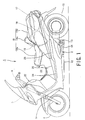
- a scooter type vehicle 1 such as two-wheeled motorcycle is equipped with a vehicle body frame 2 and a head pipe 3 provided to a front end side of the vehicle body frame 2.
- a front fork 5 rotatably supporting a front wheel 4 is connected to the head pipe 3 and a handle bar 6 is also connected to the head pipe 3 to thereby rotatably steer the front wheel 14 to right and left directions.
- Left and right pairs of upper and lower downtubes 7b and 7a extend from a rear portion of the head pipe 3 towards an obliquely rearward lower portion (only the left side pair of downtubes 7a and 7b are shown in figures).
- the lower downtube 7a extending from the rear lower portion of the head pipe 3 extends once substantially vertically downward, and then, is bent in a substantially horizontal direction so as to extend towards a rear portion, and a rear end portion thereof extends towards an obliquely upper portion of the vehicle body.
- the vehicle body frame 2 includes a pair of right and left center frames 8 extending towards an obliquely rearward upper portion from an approximately middle portion of the vertical portion of the lower downtube 7a (only the left side center frame 8 is shown in figures) and also includes a pair of sub-frames 9 extending towards a rear end portion of the lower downtube 7a from the rear end portions of the center frames 8 (only the left side sub-frame 9 is shown in figures).
- the downtube 7a and the sub-frame 9 are connected through a pivot 10.
- the vehicle body frame 2 further includes a pair of right and left seat frames 11 extending towards an oblique rearward upper portion from the rear upper portion of the sub-frame 9.
- the upper downtube 7b extends downward from the rear upper portion of the head pipe 3 substantially in parallel to the lower downtube 7a and is connected to a portion near a front end of the center frame 8.
- An engine unit 12 is mounted in a space surrounded by the lower downtube 7a, the center frame 8 and the sub-frame 9 of the vehicle body frame 2. Further, a transmission unit 13 as a power transmission device is arranged in a rear portion of the engine unit 12, and the transmission unit 13 has a front portion which is swingably mounted to the pivot 10.
- the transmission unit 13 also serves as a swing arm and is flexibly supported to be swingable to the vehicle body frame 2 through a shock absorber 14. Further, a rear wheel 15 as a drive wheel is held to a rear end of the transmission unit 13.
- the rider's seat 19 is separated into two parts in the longitudinal direction, i.e. a driver's seat 19a on which a driver sits and a pillion 19b on which a pillion passenger sits.
- the article accommodation box 18 is arranged directly below the pillion 19b.
- a waist holding backrest 19c for holding a waist portion of the driver is formed between the rider's seat 19a and the pillion 19b so as to protrude upward so that a seat surface of the pillion 19b is made higher than that of the rider's seat 19a.
- the article accommodation box (chamber) 18 is also divided into longitudinal two sections of a front box (section) 18a and a rear box (section) 18b so that two helmets 16 and 17 can be received in series in a longitudinal direction of the vehicle body.
- a floor surface of the front box 18a is formed downward towards a front direction of the vehicle body and a floor surface of the rear box 18b is formed downward towards a rear direction so that the bottom floor surface of the accommodation box 18 is formed entirely in a tapered shape ( -shape) in a side view.
- two helmets 16 and 17 are arranged in a state that head top portions thereof are directed upward and front portions thereof are directed forward in an advancing (longitudinal) direction of the vehicle.
- the head top portion of the front helmet 16 is positioned near the waist holding backrest 19c for the driver and the head top portion of the rear helmet 17 is positioned near the rear end portion of the pillion 19b as shown in Fig. 2.
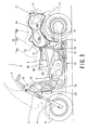
- two helmets 16 and 17 are arranged in a state that the head top portions thereof are directed upward and both the front portions thereof are directed backward in the advancing direction of the vehicle as shown in Fig. 3.
- a fuel tank 20 is arranged in a space directly below the rider's seat 19a, and an oil supply port 21 formed to the fuel tank 20 is positioned just before the front box 18a of the article accommodation box 18.
- the vehicle body frame 2 is covered around itself by a vehicle body cover 22, for example, formed of synthetic resin as a molded product.
- the vehicle body frame 2 and the vehicle body cover 22 are largely bent downward in substantially a U-shape, at a portion between the head pipe 3 and the rider's seat 19a, so as to form a foot passing space 23 extending in a width direction of the vehicle body, and a low footrest floor 24 for the rider having right and left bottom portions, on which the rider puts his (her) foot, is formed. Further, a footrest floor 25 for the pillion passenger is also formed at the rear side portions of the right and left bottom portions of the footrest floor 24.
- a tunnel-shaped portion for the engine is formed to the central portion of the footrest floor 24 as an engine tunnel 26 so as to longitudinally extend and protrude upward.
- the engine unit 12 mounted on the scooter type vehicle 1 such as two-wheeled motorcycle includes a water-cooled engine and has a structure that a radiator 27 for cooling the cooled-water engine is arranged in the vehicle body cover 22 between the front wheel 4 and the engine unit 12.
- the seat portion 19 is divided in the longitudinal direction of the vehicle body into two sections, i.e. the rider's seat 19a and the pillion 19b having the seat surface higher than that of the rider's seat 19a.
- the article accommodation box 18 is arranged substantially directly below the pillion's seat 19b and above the rear wheel 15. Accordingly, the two helmets 16 and 17 can be stored in the accommodation box 18 (18a, 18b) along the longitudinal direction of the vehicle body, so that the operation of the vehicle and a foot stepping characteristic can be improved.
- the fuel tank 20 can be arranged below the rider's seat 19a and, hence, the fuel increases or decreases in the fuel tank 20 at the portion near the center of gravity of the vehicle body. Therefore, the loads to be carried by the front wheel 4 and the rear wheel 15 are less changed and the adjusting alignment can be hence improved.
- the width of the vehicle body in the width direction in particular, the width below the seat portion 19 can be reduced by arranging two helmets 16 and 17 in the longitudinal direction in the accommodation box 18. Therefore, the reduction of the width can decrease the projected area and the mileage of the vehicle.
- the longitudinal length of the article accommodation box 18 by forming the bottom floor surface thereof so as to provide a longitudinally tapered shape ( -shape) in a side view to thereby accommodate two helmets 16 and 17 in a state that the head top portions thereof are directed upward. Moreover, it is not necessary to expand the width of the article accommodation box 18.
- article accommodation box 18 has a shape in which two helmets are arranged so as to both direct forward or rearward in the longitudinal direction of the vehicle body, the shape of the accommodation box and, hence, the vehicle body can be made smart in a plan view.
- the head top portion of the front side helmet 16 is positioned near the waist holding backrest 19c for the driver and the head top portion of the rear side helmet 17 is positioned near the rear end portion of the pillion 19b. According to such arrangement, the seating surface of the pillion 19b can be made lower and the seat stroke for the seating portion can be sufficiently ensured.
Landscapes
- Engineering & Computer Science (AREA)
- Mechanical Engineering (AREA)
- Chemical & Material Sciences (AREA)
- Combustion & Propulsion (AREA)
- General Engineering & Computer Science (AREA)
- Automatic Cycles, And Cycles In General (AREA)
Applications Claiming Priority (3)
| Application Number | Priority Date | Filing Date | Title |
|---|---|---|---|
| JP2000038753A JP4395960B2 (ja) | 2000-02-16 | 2000-02-16 | スクータ型自動二輪車の荷物収納室 |
| JP2000038753 | 2000-02-16 | ||
| EP20010103482 EP1125835B1 (fr) | 2000-02-16 | 2001-02-14 | Boíte de bagage pour véhicule du type scooter |
Related Parent Applications (1)
| Application Number | Title | Priority Date | Filing Date |
|---|---|---|---|
| EP20010103482 Division EP1125835B1 (fr) | 2000-02-16 | 2001-02-14 | Boíte de bagage pour véhicule du type scooter |
Publications (2)
| Publication Number | Publication Date |
|---|---|
| EP1553014A1 true EP1553014A1 (fr) | 2005-07-13 |
| EP1553014B1 EP1553014B1 (fr) | 2006-05-17 |
Family
ID=18562442
Family Applications (2)
| Application Number | Title | Priority Date | Filing Date |
|---|---|---|---|
| EP20010103482 Expired - Lifetime EP1125835B1 (fr) | 2000-02-16 | 2001-02-14 | Boíte de bagage pour véhicule du type scooter |
| EP05008260A Expired - Lifetime EP1553014B1 (fr) | 2000-02-16 | 2001-02-14 | Boîte de bagage pour véhicule du type scooter |
Family Applications Before (1)
| Application Number | Title | Priority Date | Filing Date |
|---|---|---|---|
| EP20010103482 Expired - Lifetime EP1125835B1 (fr) | 2000-02-16 | 2001-02-14 | Boíte de bagage pour véhicule du type scooter |
Country Status (4)
| Country | Link |
|---|---|
| EP (2) | EP1125835B1 (fr) |
| JP (1) | JP4395960B2 (fr) |
| DE (2) | DE60110851T2 (fr) |
| ES (2) | ES2262128T3 (fr) |
Cited By (1)
| Publication number | Priority date | Publication date | Assignee | Title |
|---|---|---|---|---|
| EP1759974A3 (fr) * | 2005-08-31 | 2007-03-21 | Honda Motor Co., Ltd | Motocyclette |
Families Citing this family (3)
| Publication number | Priority date | Publication date | Assignee | Title |
|---|---|---|---|---|
| JP3879437B2 (ja) * | 2000-06-23 | 2007-02-14 | スズキ株式会社 | 自動二輪車の物品収納装置 |
| JP3831186B2 (ja) * | 2000-09-08 | 2006-10-11 | 本田技研工業株式会社 | 自動二輪車の収納ボックス構造 |
| MY176258A (en) * | 2007-03-30 | 2020-07-24 | Yamaha Motor Co Ltd | Straddle-type vehiccle |
Citations (6)
| Publication number | Priority date | Publication date | Assignee | Title |
|---|---|---|---|---|
| EP0323908A2 (fr) * | 1988-01-08 | 1989-07-12 | Honda Giken Kogyo Kabushiki Kaisha | Scooter |
| JPH0288376A (ja) * | 1988-09-27 | 1990-03-28 | Honda Motor Co Ltd | 自動2輪車のへルメット収納装置 |
| US5433286A (en) * | 1988-09-27 | 1995-07-18 | Honda Giken Kogyo Kabushiki Kaisha | Motorcycle |
| EP0911253A2 (fr) * | 1997-10-21 | 1999-04-28 | Honda Giken Kogyo Kabushiki Kaisha | Unité motrice pour véhicule |
| JPH11129969A (ja) * | 1997-10-28 | 1999-05-18 | Yamaha Motor Co Ltd | スクータ型自動二輪車 |
| EP0952076A2 (fr) * | 1998-04-23 | 1999-10-27 | Yamaha Hatsudoki Kabushiki Kaisha | Véhicule du type d'un scooter |
Family Cites Families (3)
| Publication number | Priority date | Publication date | Assignee | Title |
|---|---|---|---|---|
| JPH0746617Y2 (ja) | 1987-04-27 | 1995-10-25 | 本田技研工業株式会社 | 自動二輪車 |
| JPH0524633Y2 (fr) | 1987-05-20 | 1993-06-22 | ||
| JPH0755192Y2 (ja) | 1988-08-16 | 1995-12-20 | 本田技研工業株式会社 | 物入れ付腰掛式自動車両 |
-
2000
- 2000-02-16 JP JP2000038753A patent/JP4395960B2/ja not_active Expired - Lifetime
-
2001
- 2001-02-14 ES ES05008260T patent/ES2262128T3/es not_active Expired - Lifetime
- 2001-02-14 ES ES01103482T patent/ES2239073T3/es not_active Expired - Lifetime
- 2001-02-14 EP EP20010103482 patent/EP1125835B1/fr not_active Expired - Lifetime
- 2001-02-14 EP EP05008260A patent/EP1553014B1/fr not_active Expired - Lifetime
- 2001-02-14 DE DE2001610851 patent/DE60110851T2/de not_active Expired - Lifetime
- 2001-02-14 DE DE2001619797 patent/DE60119797T2/de not_active Expired - Lifetime
Patent Citations (6)
| Publication number | Priority date | Publication date | Assignee | Title |
|---|---|---|---|---|
| EP0323908A2 (fr) * | 1988-01-08 | 1989-07-12 | Honda Giken Kogyo Kabushiki Kaisha | Scooter |
| JPH0288376A (ja) * | 1988-09-27 | 1990-03-28 | Honda Motor Co Ltd | 自動2輪車のへルメット収納装置 |
| US5433286A (en) * | 1988-09-27 | 1995-07-18 | Honda Giken Kogyo Kabushiki Kaisha | Motorcycle |
| EP0911253A2 (fr) * | 1997-10-21 | 1999-04-28 | Honda Giken Kogyo Kabushiki Kaisha | Unité motrice pour véhicule |
| JPH11129969A (ja) * | 1997-10-28 | 1999-05-18 | Yamaha Motor Co Ltd | スクータ型自動二輪車 |
| EP0952076A2 (fr) * | 1998-04-23 | 1999-10-27 | Yamaha Hatsudoki Kabushiki Kaisha | Véhicule du type d'un scooter |
Non-Patent Citations (2)
| Title |
|---|
| PATENT ABSTRACTS OF JAPAN vol. 014, no. 285 (M - 0987) 20 June 1990 (1990-06-20) * |
| PATENT ABSTRACTS OF JAPAN vol. 1999, no. 10 31 August 1999 (1999-08-31) * |
Cited By (3)
| Publication number | Priority date | Publication date | Assignee | Title |
|---|---|---|---|---|
| EP1759974A3 (fr) * | 2005-08-31 | 2007-03-21 | Honda Motor Co., Ltd | Motocyclette |
| KR100781622B1 (ko) | 2005-08-31 | 2007-12-05 | 혼다 기켄 고교 가부시키가이샤 | 자동 이륜차 |
| CN100465050C (zh) * | 2005-08-31 | 2009-03-04 | 本田技研工业株式会社 | 二轮机动车 |
Also Published As
| Publication number | Publication date |
|---|---|
| EP1125835B1 (fr) | 2005-05-18 |
| DE60119797T2 (de) | 2006-09-28 |
| ES2239073T3 (es) | 2005-09-16 |
| DE60119797D1 (de) | 2006-06-22 |
| EP1553014B1 (fr) | 2006-05-17 |
| EP1125835A3 (fr) | 2004-04-21 |
| DE60110851D1 (de) | 2005-06-23 |
| EP1125835A2 (fr) | 2001-08-22 |
| JP2001225773A (ja) | 2001-08-21 |
| JP4395960B2 (ja) | 2010-01-13 |
| ES2262128T3 (es) | 2006-11-16 |
| DE60110851T2 (de) | 2005-11-17 |
Similar Documents
| Publication | Publication Date | Title |
|---|---|---|
| CA2645626C (fr) | Capot de carenage de moto | |
| US6357542B1 (en) | Article storage area for motorcycles | |
| US6651767B2 (en) | Container box structure in two-wheeled motor vehicle | |
| EP2364901B1 (fr) | Véhicules de petite taille | |
| US7588111B2 (en) | Rear shock absorber arrangement structure for motorcycle | |
| US7140329B2 (en) | Vehicle | |
| EP3059149B1 (fr) | Structure avant de véhicule de type à enfourcher | |
| JP4986684B2 (ja) | 鞍乗り型4輪車 | |
| EP1553014B1 (fr) | Boîte de bagage pour véhicule du type scooter | |
| JPS60154970A (ja) | スク−タ型車輛 | |
| US20200070925A1 (en) | Vehicle body frame structure for saddle riding vehicle | |
| US6435585B1 (en) | Article storage device of motorcycle | |
| JP3795199B2 (ja) | 低床式自動二輪車 | |
| JP3664153B2 (ja) | スクータ型自動二輪車の荷物収納室 | |
| CN223086180U (zh) | 滑板车 | |
| JP2003237659A (ja) | スクータ型自動二輪車 | |
| JPH0342389A (ja) | 走行車両 | |
| US20080277181A1 (en) | Two person motorcycle frame | |
| JP2006103349A (ja) | 自動二輪車 | |
| JPH0386692A (ja) | スクータ型自動二輪車 | |
| JPS6192988A (ja) | 自動二輪車のリヤクツシヨンユニツト取付構造 | |
| JP2007326507A (ja) | 自動二輪車 | |
| JP2025060292A (ja) | 電動車両 | |
| JP2023048507A (ja) | 鞍乗り型車両 | |
| JP2000280960A (ja) | スクータ型自動二輪車における燃料系の配置構造 |
Legal Events
| Date | Code | Title | Description |
|---|---|---|---|
| PUAI | Public reference made under article 153(3) epc to a published international application that has entered the european phase |
Free format text: ORIGINAL CODE: 0009012 |
|
| 17P | Request for examination filed |
Effective date: 20050415 |
|
| AC | Divisional application: reference to earlier application |
Ref document number: 1125835 Country of ref document: EP Kind code of ref document: P |
|
| AK | Designated contracting states |
Kind code of ref document: A1 Designated state(s): DE ES GB |
|
| GRAP | Despatch of communication of intention to grant a patent |
Free format text: ORIGINAL CODE: EPIDOSNIGR1 |
|
| RTI1 | Title (correction) |
Free format text: ARTICLE ACCOMODATION BOX OF SCOOTER-TYPE VEHICLE |
|
| GRAS | Grant fee paid |
Free format text: ORIGINAL CODE: EPIDOSNIGR3 |
|
| GRAA | (expected) grant |
Free format text: ORIGINAL CODE: 0009210 |
|
| AKX | Designation fees paid |
Designated state(s): DE ES GB |
|
| AC | Divisional application: reference to earlier application |
Ref document number: 1125835 Country of ref document: EP Kind code of ref document: P |
|
| AK | Designated contracting states |
Kind code of ref document: B1 Designated state(s): DE ES GB |
|
| REG | Reference to a national code |
Ref country code: GB Ref legal event code: FG4D |
|
| REF | Corresponds to: |
Ref document number: 60119797 Country of ref document: DE Date of ref document: 20060622 Kind code of ref document: P |
|
| REG | Reference to a national code |
Ref country code: ES Ref legal event code: FG2A Ref document number: 2262128 Country of ref document: ES Kind code of ref document: T3 |
|
| PLBE | No opposition filed within time limit |
Free format text: ORIGINAL CODE: 0009261 |
|
| STAA | Information on the status of an ep patent application or granted ep patent |
Free format text: STATUS: NO OPPOSITION FILED WITHIN TIME LIMIT |
|
| 26N | No opposition filed |
Effective date: 20070220 |
|
| REG | Reference to a national code |
Ref country code: DE Ref legal event code: R082 Ref document number: 60119797 Country of ref document: DE Representative=s name: KLUNKER IP PATENTANWAELTE PARTG MBB, DE |
|
| PGFP | Annual fee paid to national office [announced via postgrant information from national office to epo] |
Ref country code: DE Payment date: 20200204 Year of fee payment: 20 Ref country code: ES Payment date: 20200302 Year of fee payment: 20 Ref country code: GB Payment date: 20200206 Year of fee payment: 20 |
|
| REG | Reference to a national code |
Ref country code: DE Ref legal event code: R071 Ref document number: 60119797 Country of ref document: DE |
|
| REG | Reference to a national code |
Ref country code: GB Ref legal event code: PE20 Expiry date: 20210213 |
|
| PG25 | Lapsed in a contracting state [announced via postgrant information from national office to epo] |
Ref country code: GB Free format text: LAPSE BECAUSE OF EXPIRATION OF PROTECTION Effective date: 20210213 |
|
| REG | Reference to a national code |
Ref country code: ES Ref legal event code: FD2A Effective date: 20210625 |
|
| PG25 | Lapsed in a contracting state [announced via postgrant information from national office to epo] |
Ref country code: ES Free format text: LAPSE BECAUSE OF EXPIRATION OF PROTECTION Effective date: 20210215 |