EP1550741A1 - Rotor und beschichtungsverfahren dafür - Google Patents
Rotor und beschichtungsverfahren dafür Download PDFInfo
- Publication number
- EP1550741A1 EP1550741A1 EP03751401A EP03751401A EP1550741A1 EP 1550741 A1 EP1550741 A1 EP 1550741A1 EP 03751401 A EP03751401 A EP 03751401A EP 03751401 A EP03751401 A EP 03751401A EP 1550741 A1 EP1550741 A1 EP 1550741A1
- Authority
- EP
- European Patent Office
- Prior art keywords
- rotating member
- discharge
- coating film
- coating
- hard material
- Prior art date
- Legal status (The legal status is an assumption and is not a legal conclusion. Google has not performed a legal analysis and makes no representation as to the accuracy of the status listed.)
- Withdrawn
Links
Images


Classifications
-
- C—CHEMISTRY; METALLURGY
- C23—COATING METALLIC MATERIAL; COATING MATERIAL WITH METALLIC MATERIAL; CHEMICAL SURFACE TREATMENT; DIFFUSION TREATMENT OF METALLIC MATERIAL; COATING BY VACUUM EVAPORATION, BY SPUTTERING, BY ION IMPLANTATION OR BY CHEMICAL VAPOUR DEPOSITION, IN GENERAL; INHIBITING CORROSION OF METALLIC MATERIAL OR INCRUSTATION IN GENERAL
- C23C—COATING METALLIC MATERIAL; COATING MATERIAL WITH METALLIC MATERIAL; SURFACE TREATMENT OF METALLIC MATERIAL BY DIFFUSION INTO THE SURFACE, BY CHEMICAL CONVERSION OR SUBSTITUTION; COATING BY VACUUM EVAPORATION, BY SPUTTERING, BY ION IMPLANTATION OR BY CHEMICAL VAPOUR DEPOSITION, IN GENERAL
- C23C26/00—Coating not provided for in groups C23C2/00 - C23C24/00
- C23C26/02—Coating not provided for in groups C23C2/00 - C23C24/00 applying molten material to the substrate
-
- F—MECHANICAL ENGINEERING; LIGHTING; HEATING; WEAPONS; BLASTING
- F01—MACHINES OR ENGINES IN GENERAL; ENGINE PLANTS IN GENERAL; STEAM ENGINES
- F01D—NON-POSITIVE DISPLACEMENT MACHINES OR ENGINES, e.g. STEAM TURBINES
- F01D11/00—Preventing or minimising internal leakage of working-fluid, e.g. between stages
- F01D11/08—Preventing or minimising internal leakage of working-fluid, e.g. between stages for sealing space between rotor blade tips and stator
- F01D11/12—Preventing or minimising internal leakage of working-fluid, e.g. between stages for sealing space between rotor blade tips and stator using a rubstrip, e.g. erodible. deformable or resiliently-biased part
- F01D11/122—Preventing or minimising internal leakage of working-fluid, e.g. between stages for sealing space between rotor blade tips and stator using a rubstrip, e.g. erodible. deformable or resiliently-biased part with erodable or abradable material
-
- F—MECHANICAL ENGINEERING; LIGHTING; HEATING; WEAPONS; BLASTING
- F01—MACHINES OR ENGINES IN GENERAL; ENGINE PLANTS IN GENERAL; STEAM ENGINES
- F01D—NON-POSITIVE DISPLACEMENT MACHINES OR ENGINES, e.g. STEAM TURBINES
- F01D5/00—Blades; Blade-carrying members; Heating, heat-insulating, cooling or antivibration means on the blades or the members
- F01D5/12—Blades
- F01D5/28—Selecting particular materials; Particular measures relating thereto; Measures against erosion or corrosion
- F01D5/288—Protective coatings for blades
-
- Y—GENERAL TAGGING OF NEW TECHNOLOGICAL DEVELOPMENTS; GENERAL TAGGING OF CROSS-SECTIONAL TECHNOLOGIES SPANNING OVER SEVERAL SECTIONS OF THE IPC; TECHNICAL SUBJECTS COVERED BY FORMER USPC CROSS-REFERENCE ART COLLECTIONS [XRACs] AND DIGESTS
- Y02—TECHNOLOGIES OR APPLICATIONS FOR MITIGATION OR ADAPTATION AGAINST CLIMATE CHANGE
- Y02T—CLIMATE CHANGE MITIGATION TECHNOLOGIES RELATED TO TRANSPORTATION
- Y02T50/00—Aeronautics or air transport
- Y02T50/60—Efficient propulsion technologies, e.g. for aircraft
Definitions
- the present invention relates to a rotating member such as a blade or labyrinth seal for use in a gas turbine, steam turbine, compressor or the like, and a method for coating the rotating member. More particularly, it relates to a rotating member on a part of which a coating film including a hard material is formed, and a method for coating the rotating member.
- a clearance between a rotating section and a stationary section such as a chip clearance between the blade and a casing or a shroud, or a seal clearance between the labyrinth seal and a honeycomb seal needs to be kept/set to be appropriate during operation of a gas turbine.
- the clearance is set to be excessively large fearing for contact, an efficiency of the gas turbine drops.
- the clearance is set to be excessively small, a tip end of the rotating member breaks and causes a trouble of the gas turbine.
- a tip end of a blade or a labyrinth seal is coated with an abrasive coating of a relatively hard material for chipping off the material of a contact surface of the surrounding member.
- the surrounding member is coated with an abradable coating of a material which is relatively easily chipped. Accordingly, the chip clearance or the seal clearance is adjusted to be minimized, when the side of the surrounding member is chipped off by the tip end of the rotating member by taking advantage of a hardness difference of the coating at the time of driving of the gas turbine.
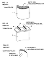
- FIG. 1A is a perspective view of a usual turbine blade
- FIG. 1B is a perspective view of the turbine blade with a chip shroud
- FIG. 1C is a perspective view of a compressor blade.
- a platform or a dovetail on a turbine disk side is omitted from these figures.
- a turbine blade 1 shown in FIG. 1A the whole surface of a blade tip end is coated with an abrasive coating 5a.
- a turbine blade 2 with a chip shroud shown in FIG. 1B the whole surfaces of the tip ends of chip fins 4 disposed on a chip shroud 3 (i.e., the tip ends of the turbine blade) are coated with abrasive coatings 5b.
- an abrasive coating 5c is applied over the region of the blade tip end (including the backside of the figure).
- FIG. 2 is a sectional view showing one example of a labyrinth seal tip end.
- the labyrinth seal is disposed in the clearance between a rotating section and a stationary section to prevent leakage of air or combustion gas, and is a seal structure frequently used in a gas turbine and compressor.
- an annular labyrinth seal 6 including concave/convex portion is disposed on a rotating section side, and a honeycomb seal (not shown) including a structure easy to be chipped off is disposed on a stationary section side.
- FIG. 2 is a sectional view cut in a plane including a center axis of the labyrinth seal 6, and an abrasive coating 5d is applied to the tip end of the convex portion of the labyrinth seal 6.
- abrasive coatings have heretofore been applied by methods such as welding, thermal spraying, and plating (e.g., see References 1 and 2).
- a welding rod or a powder body is used to coat predetermined portions such as the tip end of the turbine blade or the labyrinth seal.
- zirconia is thermally sprayed which has a small difference of thermal expansion from a mother material and whose hardness is relatively high (Vickers hardness of 1300 HV).
- abrasive grains Vickers hardness of 4500 HV
- cBN cubic boron nitride
- the coating method discharge is performed between the rotating member and an electrode on first discharge conditions such that the electrode is consumed, and the electrode is formed in accordance with a shape of a coating film forming portion. Thereafter, the coating film is formed by discharge between the electrode and the rotating member on second discharge conditions. Then, even when the electrode is not processed beforehand for a product shape, a coating object portion can appropriately be coated.
- the electrode On the first discharge conditions for consuming the electrode, the electrode is set to have a minus polarity, a pulse width is set to 1 ⁇ s or less, and a current value is set to 10 A or less.
- the electrode is preferably set to have the minus polarity, the pulse width is set to 2 to 10 ⁇ s, and the current value is set to 5 to 20 A.
- the coating has been performed by the plating or the thermal spraying. Therefore, in the production (manufacturing) of the labyrinth seal, coating pretreatments such as a blast process and a process of attaching a masking tape are required before the coating, and coating post-treatments such as a process of removing the masking tape are required after the coating. Therefore, an operation time required for the production (manufacturing) of the labyrinth seal lengthens, and it is not easy to enhance productivity of the labyrinth seal.
- the abrasive coat cannot firmly be attached to the tip edge of a seal fin. Therefore, there has been a problem that the abrasive coat easily peels off the tip edge of the seal fin and the quality level of the labyrinth seal is not stable.
- a first object of the present invention is to provide a rotating member which does not require any pretreatment or post-treatment and which has good adhesion and which is coated with a precise and abrasive coating of a relatively hard material (hereinafter referred to as a hard material in the present specification for the sake of convenience) compared to a material of an opponent component that contacts with the rotating member during rotation, and a method for coating the rotating member.
- a relatively hard material hereinafter referred to as a hard material in the present specification for the sake of convenience
- the first object is also to provide a method for forming a long-service-life coating in tests of high cycle fatigue (HCF) or low cycle fatigue (LCF) in an abrasive coated component.
- HCF high cycle fatigue
- LCDF low cycle fatigue
- a second object of the present invention is to provide a rotating member in which an area of coating of a hard material can be optimized to enhance a yield and a method for coating the rotating member.
- a third object of the present invention is to provide a rotating member in which an operation time required for production of a labyrinth seal is reduced and productivity of labyrinth components can be enhanced and a method for coating the rotating member.
- a method for coating a rotating member comprising the steps of: generating a pulsed discharge between a rotating member formed into a predetermined shape and a discharge electrode of a green compact in dielectric liquid or gas to transfer a hard material of the discharge electrode or a hard material changed from a material of the discharge electrode onto the rotating member by each discharge pulse so that a hard concavity and convexity is formed on the rotating member, wherein the green compact includes the hard material or the material changing into the hard material by the discharge; and repeatedly generating the discharge pulse to form on the rotating member a hard coating film having the concavity and convexity.
- the hard coating film is an abrasive coating film that is formed on a part of the rotating member and rubs against and shaves an opponent component.
- the coating film or a layer having good adhesion can be formed, further the coating film containing remarkably hard materials such as a cubic boron nitride (cBN) can be coated, and the hard coating film and the coating film having good abrasive properties can be formed.
- cBN cubic boron nitride
- Abrasive properties are enhanced by the treatment on a condition for a coating having coarse surface.
- the method comprises the steps of: generating discharge between the rotating member and the discharge electrode on a first discharge condition on which the discharge electrode is consumed so that a shape of the discharge electrode is made to conform to a shape of a coating film forming portion on the rotating member; and thereafter generating discharge between the discharge electrode and the rotating member on a second discharge condition to form the coating film on the rotating member.
- the discharge electrode on the first discharge condition, has a minus polarity, a pulse width is 1 ⁇ s or less, and a current value is 10 A or less, and on the second discharge condition, the discharge electrode has a minus polarity, the pulse width is 2 to 10 ⁇ s, and a current value is 5 to 20 A.
- the coating film is preferably formed on the tip end of the rotating member.
- the discharge electrode of a green compact containing one of or a mixture of cBN, TiC, TiN, TiAlN, TiB 2 , WC, Cr 3 C 2 , SiC, ZrC, VC, B 4 C, Si 3 N 4 , ZrO 2 -Y, and Al 2 O 3 .
- the material forming the hard member by the discharge is preferably one of or a mixture of Ti, Cr, W, V, Zr, Si, Mo, and Nb or a mixture of these, and these are formed into carbide by the discharge in an oil to form a hard coating film.
- a so-called discharge coating method is used according to this method, the tip end of the rotating member can easily be coated with the hard material.
- a coating film containing TiC, WC, or cBN is preferably formed on the rotating member that is driven at a low temperature
- a coating film containing cBN or Cr 3 C 2 is used in the rotating member that is driven at a high temperature
- a coating film containing ZrO 2 -Y or Al 2 O 3 is formed on the rotating member that is driven at a further high temperature.
- a fifth, sixth, seventh, and ninth invention there is provided a method of enhancing a fatigue strength of a coated surface.
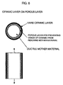
- a coating film which does not easily stretch as compared with a mother material is formed on the surface. Then, since a thin coating film bears a tensile load, the coating film on the surface easily cracks. In the coating by a discharge surface treatment, since a hard layer is firmly welded to the mother material, the crack of the coating film is developed into that of the mother material. To avoid this, it is necessary to form a coating film having a ductility, a layer for preventing the development of the crack between the mother material and the coating film, or a coating layer strong against pull.
- a ratio of a coated area coated with the hard material in a coating film forming portion, that is, coverage is suppressed, a portion not coated with the hard material, that is, the portion having the ductility is scattered and left, and the ductility is left.
- the discharge electrode is made to contain a metal which does not easily form carbide, accordingly the portion of a metal having the ductility is scattered and formed between the hard materials, and the ductility is left.
- a porous coating film mainly formed of a metal is formed as a base. Thereafter, since the coating film containing the hard material is formed on the porous coating film, the crack of the coating layer is prevented from being developed into the mother material.
- the surface of the coating layer is peened, and residual stress of compression is left. Even when the mother material stretches, a tensile stress is reduced.
- These fifth to seventh, and ninth inventions are effective not only for the coating with the hard material but also for the discharge surface treatment for forming the coating film on the surface such as wear-resistant coating.
- the eighth invention since a remarkably hard ceramic usable in the coating of the hard material is provided, it is possible to provide the coating of an effective hard material.
- a rotating member having an abrasive coating film on a part thereof that is formed by a pulsed discharge between the rotating member and a discharge electrode of a green compact in dielectric liquid or gas, wherein the green compact includes a hard material or a material that changes into a hard material by the discharge, and the abrasive coating film includes the hard material of the green compact or the hard material that is changed from the material of the green compact by the discharge.
- the rotating member is characterized in that the pretreatments such as a masking or blast process or the post-treatments such as grinding are not unnecessary and the coating film or the layer having good adhesion is formed.
- the coating film is preferably formed on the tip end of the rotating member.
- the discharge is caused between the rotating member and the discharge electrode in the dielectric liquid or gas to form an abrasive coating film including the hard material on a part of the rotating member, so that the rotating member superior in abrasive properties can be formed.
- the coating film having the ductility since the coating film having the ductility is formed, the layer for preventing the development of the crack is formed between the mother material and the coating film, and the coating layer strong against the pull is formed, the rotating member high in fatigue strength is provided.
- a remarkably hard ceramic usable in the coating of the hard material is provided, and accordingly the rotating member having good abrasive properties is provided.
- a rotating member in which only the vicinity of a portion of the rotating member having a possibility of contact with a component disposed opposite to the rotating member is coated with a hard material. Accordingly, a rotating member little in labor of operation, small in electrode use amount, good in yield of products and low in cost is obtained.
- a rotating member coated in a method for enhancing the abrasive properties of the tenth to 17th inventions is provided.
- the rotating member is coated on the conditions for a coarse surface roughness to enhance the abrasive properties.
- a 19th invention is a concrete example of the 16th invention, and there is provided a blade whose tip end is coated with a hard material. Only a corner of the blade in a rotation advance direction and the vicinity of the corner are coated with the hard material.
- the range of the coating of the hard material is optimized, the yield can be enhanced, the operation time is shortened, and the coating material can be saved.
- a 20th invention is a concrete example of the 17th invention, and there is provided a rotating member in which the coating film is formed on not all, but some of blades of a rotor or a blisk. The number of coated blades is minimized, and accordingly the operation time is reduced and the coating material can further be saved.
- the rotating member is a rotating labyrinth seal component which is one of structure elements of a labyrinth seal structure which suppresses leak of a gas or liquid between a stationary component and a rotating component.
- the rotating member comprises an annular seal component main body, and an annular seal fin integrally formed on an outer peripheral surface of the seal component main body, and a tip edge of the seal fin is coated with a hard material.
- a hard material for the coat of the hard material, an electrode for coating having consumability is used, a pulsed discharge is caused between the electrode for coating and the tip edge of the seal fin in dielectric liquid or gas, and the coat includes the hard material formed of a constituting material of the electrode for coating formed on the tip edge of the seal fin by a discharge energy or a reactant of the constituting material.
- the "electrode for coating having the consumability” means a green compact electrode (including a thermally treated green compact electrode) obtained by compression molding of a powdered metal (including a metal compound), a mixed material of the powdered metal and a powdered ceramic, or the powdered ceramic having conductivity.
- electrode for coating having the consumability also means a silicon electrode formed of solid silicon. It is to be noted that the ceramic having conductivity is appropriately subjected to a surface treatment.
- the coat of the hard material is a coating film including a hard material constituted of a constituting material of the electrode for coating or a reactant of the constituting material formed on the tip edge of the seal fin by a discharge energy generated between the electrode for coating and the tip edge of the seal fin without performing plating or thermal spraying. Therefore, in the production of the rotating labyrinth seal component, coating pretreatments such as a blast treatment and a process of attaching a masking tape and coating post-treatments such as a process of removing the masking tape are unnecessary.
- the coat of the hard material can firmly be connected to the tip edge of the seal fin.
- the coat of the hard material includes a plurality of local coating films locally formed on a plurality of portions in a peripheral direction in the tip edge of the seal fin.
- the coat of the hard material includes a plurality of local coats. Therefore, in other words, the coating film including the hard material constituted of the constituting material of the electrode for coating or the reactant of the constituting material is locally formed on a plurality of portions of the peripheral direction in the tip edge of the seal fin, not in the whole periphery of the tip edge of the seal fin. Therefore, the electrode for coating can be formed in a small and simple shape in accordance with the size or the shape of the portion to be treated in the tip edge of the seal fin. Moreover, the amount of an electrode material for use in the electrode for coating can be reduced.
- the entire rotating labyrinth seal component can have sufficient abrasive properties by the local coat of the plurality of hard materials without coating the whole periphery of the tip edge of the seal fin with the hard material.
- the electrode for coating is the green compact electrode obtained by compression molding of the powdered metal, the mixed material of the powdered metal and the powdered ceramic, or the powdered ceramic having the conductivity, or the solid silicon electrode.
- the ceramic is one of or a mixture of cBN, Cr 3 C 2 , TiC, TiN, TiAlN, TiB 2 , ZrO 2 -Y, ZrC, VC, B 4 C, WC, SiC, Si 3 N 4 , and Al 2 O 3 .
- the "powdered metal” also includes a powdered metal compound. It is to be noted that a ceramic that does not have conductivity is appropriately subjected to the surface treatment so as to secure the conductivity.
- a labyrinth seal structure which suppresses a leakage of a gas or liquid between a stationary component and a rotating component, comprising: a stationary-side seal component integrally disposed on the stationary component; an annular seal component main body which is disposed inside the stationary-side seal component and which is capable of rotating integrally with the rotating component and which is integrally disposed on the rotating component; an annular seal fin integrally formed on an outer peripheral surface of the seal component main body; and a hard coat formed on the tip edge of the seal fin, wherein the hard coat is a coating film including a hard material constituted of a constituting material or a reactant of the constituting material of an electrode for coating formed on the tip edge of the seal fin by a discharge energy of a pulsed discharge between the electrode for coating and the tip edge of the seal fin, and the electrode for coating has consumability.
- the "stationary-side seal component” includes a honeycomb-shaped stationary honeycomb seal component, or a stationary abradable seal component whose inside is coated with an abradable coat.
- the "electrode for coating having the consumability” means a green compact electrode (including a thermally treated green compact electrode) obtained by compression molding of a powdered metal (including a metal compound), a mixed material of the powdered metal and a powdered ceramic, or the powdered ceramic having conductivity.
- the "electrode for coating having the consumability” also means a silicon electrode formed of solid silicon. It is to be noted that for the ceramic which does not have the conductivity, the surface of the ceramic powder which does not have the conductivity is subjected to a treatment for forming a conductive coating film so as to appropriately secure the conductivity.
- the rotating labyrinth seal component includes the coat of the hard material. Therefore, to integrally rotate the rotating labyrinth seal component with the rotating component, even when the stationary-side seal component is deformed, and the rotating labyrinth seal component contacts with the stationary-side seal component, the stationary-side seal component is simply shaved by the coat of the hard material in the rotating labyrinth seal component, and the rotating labyrinth seal component is hardly shaved.
- a clearance between the stationary-side seal and the rotating labyrinth seal component is inhibited from being enlarged during the rotation of the rotating component, and a seal effect of the labyrinth seal structure can be kept in an appropriate state.
- the rotating labyrinth seal component is set so as to slightly contact with the stationary-side seal component during initial rotation of the rotating component. Accordingly, during or after the initial rotation, the clearance between the stationary-side seal component and the rotating labyrinth seal component can be reduced as much as possible, and the seal effect of the labyrinth seal structure can further be enhanced.
- the coat of the hard material is the coating film including the hard material constituted of the constituting material of the electrode for coating or the reactant of the constituting material formed on the tip edge of the seal fin by the discharge energy generated between the electrode for coating and the tip edge of the seal fin without performing the plating or thermal spraying. Therefore, in the production of the rotating labyrinth seal component, the coating pretreatments such as the blast treatment and the process of attaching the masking tape and the coating post-treatments such as the process of removing the masking tape are unnecessary.
- the boundary portion between the coat of the hard material coated by the discharge energy and the mother material of the seal fin has alloy composition changing properties, the coat of the hard material can firmly be connected to the tip edge of the seal fin.
- the coat of the hard material includes a plurality of local coating films locally formed on a plurality of portions in the peripheral direction in the tip edge of the seal fin.
- the coat of the hard material includes a plurality of local coats of the hard material. Therefore, in other words, the coating film including the hard material constituted of the constituting material of the electrode for coating or the reactant of the constituting material is locally formed on a plurality of portions to be treated of the peripheral direction in the tip edge of the seal fin, not in the whole periphery of the tip edge of the seal fin. Therefore, the electrode for coating can be formed into the small and simple shape in accordance with the size or the shape of the portion to be treated in the tip edge of the seal fin. Moreover, the amount of the electrode material for use in the electrode for coating can be reduced.
- the entire rotating labyrinth seal components can have sufficient abrasive properties by the local coats of the plurality of hard materials without coating the whole periphery of the tip edge of the seal fin with the hard material.
- a method for manufacturing a rotating member of a blade or a labyrinth member comprising: a first step of forming a forging material or a casting material into a predetermined shape by mechanical processing; and a second step of generating a pulsed discharge between a rotating member formed into a predetermined shape and a discharge electrode of a green compact or solid silicon in dielectric liquid or gas to transfer a hard material of the discharge electrode or the hard material changed from a material of the discharge electrode onto the rotating member by each discharge pulse so that a hard concavity and convexity is formed on the rotating member, wherein the green compact includes the hard material or the material changing into the hard material by the discharge, and repeatedly generating the discharge pulse to form on the rotating member a hard coating film having the concavity and convexity.
- an abrasive coating film that rubs against and shaves an opponent component is formed as the hard coating film on a part of the rotating member.
- the method for manufacturing the rotating member wherein the second step comprises the steps of forming a discharge electrode into a shape in accordance with a shape of a predetermined portion of the rotating member.
- a discharge condition is controlled to set a coverage to be 95% or less in the coating film forming portion, the coverage being a ratio of an area at which the coating film including the hard material is formed.
- a 30th invention there is provided the method of manufacturing the rotating member, wherein the ratio of the coverage is controlled to provide the rotating member which does not easily collapse from fatigue.
- a 31st invention there is provided the method for manufacturing the rotating member which does not easily collapse from fatigue, wherein in the second step, the green compact electrode containing 5% or more by volume of a metal which does not easily react into carbide is used to perform the discharge.
- a 32nd invention there is provided the method for manufacturing the rotating member which does not easily collapse from fatigue, wherein the second step comprises the steps of: forming a porous coating film on a coating film forming portion of the rotating member; and thereafter forming the coating film including the hard material on the porous coating film.
- the method for manufacturing the rotating member superior in abrasive properties by using the appropriate discharge electrode material of the green compact in the second step.
- a 34th invention there is provided the method of manufacturing the rotating member which does not easily collapse from fatigue, further comprising: a third step of subjecting the coating film formed in the second step to a peening treatment.
- FIG. 3 is a diagram showing a first embodiment of a rotating member and coating method of the present invention. This figure shows that a tip end of a blade 1 for use in a gas turbine or a compressor is coated with a hard material.
- FIG. 3 shows an example of the blade, but a labyrinth seal which is the same rotating member can also be coated with the hard material in a similar method.
- reference numeral 13 denotes the blade fixing jig.
- cBN is used as the hard material
- cBN is a coating material optimum for the turbine blade exposed at a high temperature, in that Vickers hardness is 4500 HV at room temperature, and Vickers hardness close to 2000 HV can be maintained even at high temperature of 900°C or more.
- a hard material of TiC, WC can be used in the rotating member for use at a low temperature
- Cr 3 C 2 can be used in the rotating member for use at a high temperature
- ZrO 2 -Y or Al 2 O 3 can be used in the rotating member for use at a further high temperature.
- a coating film containing TiC, WC, or cBN is formed on the rotating member for use at the low temperature
- a coating film containing cBN or Cr 3 C 2 is used in the rotating member for use at the high temperature
- a coating film containing ZrO 2 -Y or Al 2 O 3 is formed on the rotating member for use at the further high temperature.
- these hard materials may also be mixed to form an optimum coating film.
- a discharge coating technique is disclosed, for example, in "Surface Treatment Method of Metal Material by In-liquid Discharge" of Japanese Laid-Open Patent Publication No. 7-197275, and the description is omitted.
- ceramics such as cBN are hard insulating materials, a single ceramic such as cBN cannot be formed into the discharge electrode, but the discharge electrode containing the ceramics such as cBN can be formed by use of a conductive binder.
- a conductive binder For example, Co-based alloy powder can be used as a binder, and ceramic powder such as cBN may be mixed with a Co-based alloy powder, charged in a press mold, and compressed/molded. It is to be noted that an amount of binder is preferably about 50% or more by a volume ratio.
- the powder of ceramics such as cBN may be coated with titanium (Ti), nickel (Ni), or cobalt (Co) which is a binder to form the discharge electrode.
- a particle diameter of the whole powder needs to be smaller than a pole distance between the electrode and a work during a discharge surface treatment, and is therefore preferably about 10 ⁇ m or less.
- the powder of ceramics such as cBN can easily be coated with a thin coating film of a Ti, Ni, or Co metal by vapor deposition.
- the discharge can be caused in the portion of the binder, the discharge electrode is brought into a molten state by heat energy, and a part of the discharge electrode can be welded/attached to the tip end of the rotating member such as the blade.
- the tip end of the rotating member can be coated with a hard coating film containing the ceramics such as cBN.
- Table 1 shows results of a wear test in which two test pieces (upper and lower test pieces) coated by the coating method of the present invention are ground (rubbed) with each other at the high temperature.
- Coating material Wear amount ( ⁇ m) Upper test piece Ni alloy 600 or more Lower test piece cBN coating 0
- the upper test piece is RENE77 which is a nickel-based alloy
- the lower test piece is cBN which is the coating film of the present invention.
- temperature 800 degrees centigrade
- surface pressure 7 MPa
- cycle number 10 7 cycles
- amplitude 0.35 mm.
- a wear amount of 600 ⁇ m or more is measured on an Ni alloy, but no wear is detected on the coating film of cBN. From this result, it is seen that cBN is superior in abrasive properties.
- this Ni alloy is an alloy constituted of a component ratio of Ni: 57%, Cr: 15%, Co: 15%, Mo: 5%, Ti: 3.5%, Al: 4.4, C: 0.1%.
- the hard coat can easily be applied by use of characteristics of the ceramics such as cBN, and a coating film having good adhesion and quality level can be coated as compared with conventional methods such as welding and thermal spraying.
- a thin coating film (or a layer) that has a thickness of several microns to 30 ⁇ m can be formed, the coating film is not easily cracked, and precision can be controlled by a unit of several ⁇ m. Therefore, it is possible to provide a coating method optimum for precision components such as the blade and labyrinth seal.
- Coarser surface roughness for abrasive properties of shaving the opponent component to be ground is preferable.
- the surface roughness is coarser than 1.2 ⁇ mRa.
- the so-called discharge coating method is used in the present invention, the pretreatments such as the masking and blast process are unnecessary, the coating film having good adhesion can easily and inexpensively be formed, and further a coating film containing ceramics such as cubic boron nitride (cBN) can be coated. Therefore, a portion of the rotating member requiring the abrasive properties can be coated with a hard coating film superior in abrasive properties.
- cBN cubic boron nitride
- a coating layer of the hard material is hard, and small in ductility. Therefore, a tensile stress applied to the component is not borne by a mother material in a component having a large ductility, and is borne only by the coating layer of the surface. Therefore, the surface cracks, and there is a possibility that the crack is developed into the mother material. To avoid this, a method of imparting the ductility to the coating layer is used.
- Table 2 shows the number of cycles reaching destruction in a high cycle fatigue (HCF) test in which an outer diameter of a round rod is coated with the hard material and a tensile load is going to be repeated in an axial direction.
- HCF high cycle fatigue
- the material does not break up to one million cycles.
- a coverage (see FIG. 4) of coating is 98%
- the material breaks at 20 thousand cycles.
- the coverage is suppressed at about 95%, the material does not break up to one million cycles.
- Coating state Cycle number of break No coating One million cycles 98% coverage of TiC 20 thousand cycles 95% coverage of TiC
- HFC test conditions 500°C, 650 MPa, pull of round rod having a diameter of 5 mm in axial direction at 30 Hz
- the abrasive properties of the whole coating surface are slightly sacrificed to increase the ductility.
- the coverage is raised, the ductility decreases, and fatigue strength drops.
- the fatigue strength does not largely drop, and the abrasive properties little drop.
- a discharge time is reduced, a range in which the discharge does not occur is left, and the coverage can be reduced.
- the treatment is usually performed for a time of five minutes/square centimeter, but the time may be reduced to about 3.8 minutes/square centimeter.
- Time for obtaining a coverage of 95% time for obtaining a coverage of 98%*LOG(1-0.95)/LOG(1- 0.98). The coverage of 98% is regarded as a coverage of 100%. To calculate the time from a time for obtaining a coverage of 50%, 0.98 in LOG(1-0.98) is changed to 0.5.
- a porous layer is formed as a base for the coating layer of the hard material in order to prevent the crack of the coating layer from being developed into the mother material.
- the porous layer is formed under the coating layer.
- This base is also formed by discharge coating.
- the porous layer having a thickness of 0.05 mm or more can be formed by using the electrode obtained by compression molding of a powder of metals such as Stellite. Thereafter, the porous layer is coated with the hard material.
- the surface of the coating of the hard material is peened, the surface is accordingly stretched, a compression stress is left, and a tensile stress is reduced even when the mother material is elongated.
- the fatigue strength can be enhanced by the effect.
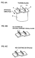
- FIGS. 7A to 7C, 8A to 8C, 9A and 9B are perspective views showing fifth to seventh embodiments of the rotating member of the present invention. It is to be noted that in these figures, a platform or a dovetail on a disk side is omitted.
- the corner of the blade in a rotation advance direction that is, the blade tip end of a blade surface on the back side and a tip end surface are coated with a coating 20 of the hard material.
- the blade tip end of a blade surface on the back side and the entire tip end surface are coated, and the opposite surface may not be coated.
- the blade tip end of a blade surface on the back side is coated, and the entire tip end surface is not coated.
- the corner of the tip end of a chip fin 4 in the rotation advance direction, or the surface of the chip fin 4 in the rotation advance direction, that is, the backside surface of the tip end of the chip fin 4 on are coated with a coating 21 of the hard material.
- the chip shroud 3 is disposed to prevent resonance of the blades 2 at the time of a high-speed rotation of the gas turbine and to prevent a high-temperature gas from leaking to the outside of the blades 2.
- the entire surface of the tip end and the surface of the rotation advance direction i.e., on the backside surface of the tip end of the chip fin 4) are coated, and the opposite surface may not be coated.
- the surface of the rotation advance direction i.e., the backside surface of the tip end
- the whole surface of the tip end is not coated.
- the corner of the blade in the rotation advance direction that is, the blade tip end of a blade surface on the front side and the tip end surface are coated with a coating 22 of the hard material.
- the surface of the rotation advance direction that is, the blade tip end of a blade surface on the front side is coated, and the entire surface of the tip end is not coated.
- the coating of the hard material is applied so as to shave the abradable coating by the tip ends of the blades 1, 2 by taking advantage of the hardness difference, at the time of driving the blades 1, 2 to keep a minimum chip clearance.
- the abradable coating is applied on the casing or the shroud.
- this phenomenon starts by the contact between the casing or the shroud and the corners of the blades 1, 2 in the rotation advance direction, and ends when the casing or the shroud is shaved. That is, after the contact of the corner, another portion of the same blade hardly contacts with the casing or the shroud.
- the coating of the hard material does not have to be applied over the entire region of the blade tip end as in the related art.
- the range to be coated is narrowed, the yield of products is enhanced, the operation time can be shortened, the expensive coating material can be saved, and the cost can be reduced.
- FIG. 10 is a diagram showing a fifth embodiment of the coating method according to the present invention, and is a diagram showing the coating method of the blades shown in FIGS. 7A to 7C.
- the blade 1 and a discharge electrode 23 is submerged in the processing tank 12 filled with the dielectric liquid (oil), the discharge electrode 23 is disposed in the vicinity of the corner in the rotation advance direction of the blade 1, the discharge is caused between them, and only the corner of the blade 1 in the rotation advance direction is coated with the coating 20 of the hard material.
- the coating 20 of the hard material is formed to have a very thin thickness of 10 to 20 ⁇ m (exaggerated for ease of seeing in the figure). Therefore, after molding the blade 1 as usual, it is sufficient to apply the coating 20 of the hard material only to a range of contact with the opposite member, that is, only the corner of the rotation advance direction or the surface of the rotation advance direction. Needless to say, the corner of the blade 1 is shaved by the thickness of the coating 20 of the hard material by machine processing, and a casting mold in consideration of the thickness beforehand may be used to mold the blade 1.
- the coating of the hard material may be formed entirely on the rotation advance direction surface and the tip end surface.
- the surface disposed opposite to the rotation advance direction surface does not have to be coated.
- the discharge electrode 23 shaped so as to coat only the blade tip end of the blade surface on the back side and the tip end surface is preferably used so that only the corner of the blade 1 in the rotation advance direction can be subjected to the discharge coating.
- the discharge electrode 23 has a substantially L-shaped section, and a shape curved along the back side of the blade.
- the electrode may be processed beforehand into a product shape.
- the electrode may be formed in accordance with the product shape by the discharge on the discharge condition on which the electrode is easily consumed.
- the electrode is set to have a minus polarity, and the discharge is caused on comparatively small energy condition on which the pulse width is set to 1 ⁇ s or less, and the current value is 10 A or less. Then, the damage onto the product is suppressed, and the electrode can accord with the product shape.
- the electrode When the coating film is formed, the electrode is assumed to have the minus polarity, and the discharge is caused on comparatively large energy condition on which the pulse width is about 2 to 10 ⁇ s, and the current value is about 5 to 20 A.
- the discharge is caused on the surfaces disposed opposite to each other by application of a voltage between the blade 1 and the discharge electrode 23 submerged in the dielectric liquid, the surface of the discharge electrode 23 is molten by the discharge, and the molten element is attached on the surface of the blade 1 to form the alloy on the surface.
- a solidified coating material is used for the discharge electrode 23.
- the discharge coating is a coating method optimum for the precision components such as the blade 1. Moreover, a place where the discharge does not occur is not coated. Therefore, since the portion to be coated can locally be coated, the pretreatments such as the masking are unnecessary. Since heat generation is small, the blade is not thermally deformed, and the post-treatment is also unnecessary.
- the coating range of the hard material is optimized, the yield of products can be enhanced. Since the operation time can be shortened, and the coating material can be saved, the cost can be reduced. Furthermore, since the so-called discharge coating is used, only the corner of the rotation advance direction of the blade or the surface of the rotation advance direction can easily and inexpensively can be coated with the hard material.
- FIG. 11 is a schematic diagram of a labyrinth seal structure according to an eighth embodiment of the rotating member of the present invention
- FIG. 12 is a front view of a labyrinth seal of FIG. 11.
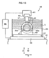
- FIG. 13 is a schematic diagram of a discharge processing machine according to the eighth embodiment of the coating method according to the present invention.
- a labyrinth seal structure 31 is used in the gas turbine of a jet engine, and inhibits a leak of a combustion gas between an engine stationary component 33 and an engine rotating component 35.
- the labyrinth seal structure 31 includes, as constituting elements, a honeycomb-shaped stationary-side honeycomb seal component 37 integrally disposed on the engine stationary component 33, and a rotating labyrinth seal component 39 disposed inside the stationary-side honeycomb seal component 37 and capable of rotating integrally with the engine rotating component 35.
- a stationary-side abradable seal component whose inside is coated with the abradable coat may also be used instead of the stationary-side honeycomb seal component 37.
- a concrete constitution of the rotating labyrinth seal component 39 which is an important part of the embodiment of the present invention is as follows.
- annular seal component main body 41 which is a main body of the rotating labyrinth seal component 39 is integrally disposed on the engine rotating component 35, and a plurality of annular seal fins 43 are integrally formed on the outer peripheral surface of the seal component main body 41. Tip edges of the respective seal fins 43 are coated with coats 45 of the hard material. Furthermore, for each coat 45 of the hard material, an electrode 47 for coating having consumability (see FIG. 13) is used, and a pulsed discharge is caused between the electrode 47 for coating and the tip edge of the seal fin 43.
- the constituting material of the electrode 47 for coating or the reactant of the constituting material forms into the coating film containing the hard material on a plurality of treated portions in the tip edges of the seal fins 43 by the discharge energy, and accordingly a plurality of (four in the embodiment of the present invention) local coats 45a of the hard material are applied at equal intervals.
- the electrode for coating having the consumability means a green compact electrode (including a thermally treated green compact electrode) obtained by compression molding of a powdered metal (including a metal compound), a mixed material of the powdered metal and a powdered ceramic, or the powdered ceramic having conductivity.
- the electrode for coating having the consumability may also mean a silicon electrode formed of solid silicon. It is to be noted that the ceramic having conductivity is subjected to the surface treatment for forming a conductive coating film on the ceramic powder, and molded by compression, so that the conductivity is secured.
- examples of the "powdered metal” include Ti, Co, and the like
- the examples of the “powdered ceramic” include cBN, TiC, TiN, TiAlN, AlN, TiB 2 , WC, Cr 3 C 2 , SiC, ZrC, VC, B 4 C, Si 3 N 4 , ZrO 2 -Y, Al 2 O 3 , and the like.
- the examples of the material which reacts by the discharge energy to form the coating film containing the hard material include Ti, W, Cr, Zr, Si, V, Mo, Nb.
- the electrode 47 for coating has a shape approximate to that of the portion to be treated in the tip edges of the seal fins 43.
- a bed 51 is used as a processing machine base, and a table 53 is disposed on the bed 51.
- the table 53 can be moved in X-axis directions (left and right directions in FIG. 13) by driving an X-axis servo motor (not shown), and can be moved in Y-axis directions (front and back directions of a sheet surface of FIG. 13) by driving a Y-axis servo motor (not shown).
- a processing head 61 is disposed via a column (not shown) above the bed 51 (above in FIG. 13), and this processing head 61 can move in Z-axis directions (upward and downward directions in FIG. 13) by driving a Z-axis servo motor. Moreover, an electrode hold member 63 for holding the electrode 47 for coating is disposed on the processing head 61.
- the electrode hold member 63 and the support tool 59 are electrically connected to a power supply 65.
- the seal component main body 41 is fixed by the support tool 59 in a state in which a portion of the tip edge of the seal fin 43 to be treated in the peripheral direction is directed right upwards in the processing tank 55.
- the table 53 is moved in the X-axis and Y-axis directions (at least either one direction) by driving the X-axis and Y-axis servo motors. Thereby, the position of the seal fin 43 is determined such that the portion of the tip end of the seal fin 43 to be treated faces the electrode 47 for coating.
- the electrode 47 for coating is moved integrally with the processing head 61 in the Z-axis direction by driving the Z-axis servo motor, while a pulsed voltage is generated between the electrode 47 for coating and the portion of the tip end of the tip fin 43 to be treated in the dielectric liquid L. Accordingly, the electrode material of the electrode 47 for coating is locally diffused in and/or welded to the portion of the tip edge of the seal fin 43 to be treated by the discharge energy, and the portion of the tip edge of one seal fin 43 to be treated can locally be coated with a local coat 45a of the hard material.
- the position of another seal fin 43 is determined such that the portion of the tip fin of the seal fin 43 to be treated faces the electrode 47 for coating. Then, as described above, the electrode material of the electrode for coating 47 is locally diffused in and/or welded to the portion of the tip edge of this seal fin 43 to be treated by the discharge energy, and the portion of the tip edge of the seal fin 43 to be treated is locally coated with the local coat 45a of the hard material.
- the rotating labyrinth seal component 39 includes the coat 45 of the hard material. Therefore, to integrally rotate the rotating labyrinth seal component 39 and the engine rotating component 35, even when the engine stationary component is deformed and the rotating labyrinth seal component 39 contacts with the stationary-side honeycomb seal component 37, the stationary-side honeycomb seal component 37 is only shaved by the coat 45 of the hard material in the rotating labyrinth seal component 39.
- the rotating labyrinth seal component 39 is substantially hardly shaved.
- the clearance between the stationary-side honeycomb seal component 37 and the rotating labyrinth seal component 39 is inhibited from increasing during the rotation of the engine rotating component 35, and the seal effect of the labyrinth seal structure 31 can be kept in an appropriate state.
- the rotating labyrinth seal component 39 is set beforehand so as to slightly contact with the stationary-side honeycomb seal component 37 at the time of the initial rotation of the engine rotating component 35. Accordingly, the clearance between the stationary-side honeycomb seal component 37 and the rotating labyrinth seal component 39 can be set to be as small as possible during and after the initial rotation, and the seal effect of the labyrinth seal structure 31 can further be enhanced.
- coating of the coats 45 of the hard material is performed on the portions of the tip edges of the seal fins 43 by diffusing and/or welding of the electrode material of the electrode 47 for coating by the discharge energy generated between the electrode for coating 47 and the portion of the tip edge of the seal fin 43 without performing the plating or thermal spraying. Therefore, in the production of the rotating labyrinth seal component 39, the coating post-treatments such as the blast treatment and the process of removing the masking tape are unnecessary.
- the boundary portion between the coat 45 of the hard material formed by the discharge energy and the mother body of the seal fin 43 has alloy composition changing properties, and the coat of the hard material can firmly be connected to the tip edge of the seal fin 43.
- the coat 45 of the hard material includes a plurality of local coats 45a of the hard material.
- the electrode material 47 of the electrode for coating is locally diffused in and/or welded to a plurality of portions to be treated of the peripheral direction in the tip edge of the seal fin 43, not in the whole periphery of the tip edge of the seal fin 43. Therefore, the electrode 47 for coating can be formed to have a small and simple shape in accordance with the size and/or the shape of the portion of the tip edge of the seal fin 43 to be treated. Accordingly, the amount of the electrode material used to form the electrode 47 for coating can be reduced.
- the coat 45 of the hard material (local coat 45a of the hard material) can firmly be connected to the tip edge of the seal fin 43. Therefore, even when the entire tip edge periphery of the seal fin 43 is not coated with the coat 45 of the hard material, the sufficient abrasive properties of the entire rotating labyrinth seal component 39 can be achieved by a plurality of local coats 45a of the hard material.
- the coating pretreatments such as the blast process and the process of attaching the masking tape, and the coating post-treatments such as the process of removing the masking tape are not required. Therefore, the operation time required for the production of the rotating labyrinth seal component 39 is reduced, and it is easy to enhance the productivity of the rotating labyrinth seal components 39.
- the coat 45 of the hard material can firmly be connected to the tip edge of the seal fin 43, the coat 45 of the hard material does not easily peel off from the tip edge of the seal fin 43, and the quality level of the rotating labyrinth seal component 39 is stabilized.
- the entire rotating labyrinth seal component 39 has sufficient abrasive properties, and the electrode 47 for coating can be formed to have the small and simple shape in accordance with the size/shape of the portion to be treated of the tip edge in the seal fin 43. Moreover, the amount of the electrode material used to form the electrode for coating 47 can be reduced. Therefore, the production cost of the rotating labyrinth seal component 39 can be reduced.
- the present invention is not limited to the description of the embodiment of the present invention.
- the discharge in the dielectric liquid L instead of the discharge in the electrically insulating gas can be performed.
- various modifications can be carried out.
- the coating pretreatments such as the blast process and the process of attaching the masking tape
- the coating post-treatments such as the process of removing the masking tape
- the coat of the hard material can firmly be connected to the tip edge of the seal fin, the coat of the hard material does not easily peel off from the tip edge of the seal fin, and the quality level of the labyrinth seal is stabilized.
- the entire rotating labyrinth seal component has sufficient abrasive properties, and the electrode for coating can be formed to have the small and simple shape in accordance with the size/shape of the portion to be treated of the tip edge in the seal fin. Moreover, the amount of the electrode material used to form the electrode for coating can be reduced. Therefore, the production cost of the rotating labyrinth seal component can be reduced.
Landscapes
- Engineering & Computer Science (AREA)
- Chemical & Material Sciences (AREA)
- Mechanical Engineering (AREA)
- Materials Engineering (AREA)
- General Engineering & Computer Science (AREA)
- Chemical Kinetics & Catalysis (AREA)
- Metallurgy (AREA)
- Organic Chemistry (AREA)
- Other Surface Treatments For Metallic Materials (AREA)
- Structures Of Non-Positive Displacement Pumps (AREA)
Applications Claiming Priority (7)
| Application Number | Priority Date | Filing Date | Title |
|---|---|---|---|
| JP2002295966A JP4096301B2 (ja) | 2002-10-09 | 2002-10-09 | 動翼及びそのコーティング方法 |
| JP2002295964 | 2002-10-09 | ||
| JP2002295964 | 2002-10-09 | ||
| JP2002295966 | 2002-10-09 | ||
| JP2003167075 | 2003-06-11 | ||
| JP2003167075 | 2003-06-11 | ||
| PCT/JP2003/012945 WO2004033755A1 (ja) | 2002-10-09 | 2003-10-09 | 回転体及びそのコーティング方法 |
Publications (2)
| Publication Number | Publication Date |
|---|---|
| EP1550741A1 true EP1550741A1 (de) | 2005-07-06 |
| EP1550741A4 EP1550741A4 (de) | 2011-05-25 |
Family
ID=32096707
Family Applications (1)
| Application Number | Title | Priority Date | Filing Date |
|---|---|---|---|
| EP03751401A Withdrawn EP1550741A4 (de) | 2002-10-09 | 2003-10-09 | Rotor und beschichtungsverfahren dafür |
Country Status (7)
| Country | Link |
|---|---|
| US (3) | US7537809B2 (de) |
| EP (1) | EP1550741A4 (de) |
| KR (1) | KR101004236B1 (de) |
| CN (1) | CN1692179B (de) |
| CA (1) | CA2483528C (de) |
| TW (1) | TWI272993B (de) |
| WO (1) | WO2004033755A1 (de) |
Cited By (4)
| Publication number | Priority date | Publication date | Assignee | Title |
|---|---|---|---|---|
| CN102523747A (zh) * | 2010-09-16 | 2012-06-27 | 三菱电机株式会社 | 放电表面处理方法 |
| EP2604797A1 (de) | 2011-12-13 | 2013-06-19 | MTU Aero Engines GmbH | Laufschaufel mit einer Rippenanordnung mit abrasiver Beschichtung |
| DE102015206516A1 (de) * | 2015-04-13 | 2016-10-13 | MTU Aero Engines AG | Labyrinthdichtung mit verbesserten Dichtrippen |
| EP2574545A3 (de) * | 2011-09-30 | 2017-10-11 | Rolls-Royce plc | Verschleißfeste Beschichtung und Verwendung davon |
Families Citing this family (47)
| Publication number | Priority date | Publication date | Assignee | Title |
|---|---|---|---|---|
| US9284647B2 (en) * | 2002-09-24 | 2016-03-15 | Mitsubishi Denki Kabushiki Kaisha | Method for coating sliding surface of high-temperature member, high-temperature member and electrode for electro-discharge surface treatment |
| EP1544321B1 (de) * | 2002-09-24 | 2016-08-10 | IHI Corporation | Verfahren zum beschichten der gleitfläche eines hochtemperaturelements |
| TWI272993B (en) * | 2002-10-09 | 2007-02-11 | Ishikawajima Harima Heavy Ind | Method for coating rotary member, rotary member, labyrinth seal structure and method for manufacturing rotary member |
| SG155059A1 (en) * | 2003-06-11 | 2009-09-30 | Ishikawajima Harima Heavy Ind | Repair method for machine component, production method of restored machine component, production method of machine component, gas turbine engine, electric spark machine, repair method for turbine component and production method for restored turbine compo |
| JP4534633B2 (ja) * | 2004-07-02 | 2010-09-01 | 三菱電機株式会社 | 放電表面処理方法及び表面処理が施された金型 |
| WO2006095799A1 (ja) * | 2005-03-09 | 2006-09-14 | Ihi Corporation | 表面処理方法及び修理方法 |
| US20060201868A1 (en) * | 2005-03-11 | 2006-09-14 | Simmons Blake A | Methods and devices for high-throughput dielectrophoretic concentration |
| EP1715140A1 (de) * | 2005-04-21 | 2006-10-25 | Siemens Aktiengesellschaft | Turbinenschaufel mit einer Deckplatte und einer auf der Deckplatte aufgebrachte Schutzschicht |
| JP4830812B2 (ja) | 2006-11-24 | 2011-12-07 | 株式会社Ihi | 圧縮機動翼 |
| EP2141262A4 (de) * | 2007-03-26 | 2011-07-13 | Ihi Corp | Hitzebeständiges bauteil |
| RU2477679C2 (ru) * | 2007-03-30 | 2013-03-20 | АйЭйчАй КОРПОРЕЙШН | Способ ремонта изношенной торцевой части металлической пластины |
| US8205335B2 (en) * | 2007-06-12 | 2012-06-26 | United Technologies Corporation | Method of repairing knife edge seals |
| EP2153038B1 (de) * | 2007-06-13 | 2012-09-12 | ACC- La Jonchere | Ein mehrlagiges schiebeglied enthaltende dichtung und entsprechendes herstellungsverfahren |
| JP5101317B2 (ja) | 2008-01-25 | 2012-12-19 | 三菱重工業株式会社 | シール構造 |
| DE102009016803A1 (de) * | 2009-04-09 | 2010-10-14 | Rolls-Royce Deutschland Ltd & Co Kg | Labyrinth-Anstreifdichtung für eine Strömungsmaschine |
| SG166033A1 (en) * | 2009-05-08 | 2010-11-29 | Pratt & Whitney Services Pte Ltd | Method of electrical discharge surface repair of a variable vane trunnion |
| JP5423795B2 (ja) | 2009-07-28 | 2014-02-19 | 三菱電機株式会社 | 耐エロージョン性機械部品及び機械部品の表面層形成方法並びに蒸気タービンの製造方法 |
| DE102009055914A1 (de) * | 2009-11-27 | 2011-06-09 | Rolls-Royce Deutschland Ltd & Co Kg | Dichtringe für eine Labyrinthdichtung |
| CN102218638B (zh) * | 2010-04-14 | 2012-11-28 | 王茂才 | 一种燃气轮机叶片微弧沉积涂层修复工艺方法 |
| EP2386726B1 (de) * | 2010-05-12 | 2012-10-31 | Siemens Aktiengesellschaft | Kanalwandabschnitt für einen ringförmigen Strömungskanal einer Axialturbomaschine mit Radialspalteinstellung, zugehöriger Axialverdichter und Gasturbine |
| US20130071251A1 (en) | 2010-05-24 | 2013-03-21 | Jose Javier Bayod Relancio | Vibration damping blade for fluid |
| US8512098B1 (en) * | 2010-09-28 | 2013-08-20 | Jeffrey Bonner | Machining technique using a plated superabrasive grinding wheel on a swiss style screw machine |
| CN102343392A (zh) * | 2011-06-14 | 2012-02-08 | 昆山市瑞捷精密模具有限公司 | 一种具有硬膜结构的铁素体不锈钢模具的制备方法 |
| DE102011087207A1 (de) * | 2011-11-28 | 2013-05-29 | Aktiebolaget Skf | Labyrinthdichtung mit unterschiedlich verschleißenden Labyrinthringen |
| FR2985759B1 (fr) | 2012-01-17 | 2014-03-07 | Snecma | Aube mobile de turbomachine |
| US20140224859A1 (en) * | 2012-02-29 | 2014-08-14 | Sumitomo Electric Industries, Ltd. | Coated rotary tool and method for manufacturing the same |
| JP6064987B2 (ja) | 2012-02-29 | 2017-01-25 | 住友電気工業株式会社 | 被覆回転ツールおよびその製造方法 |
| JP5932538B2 (ja) * | 2012-07-20 | 2016-06-08 | 株式会社東芝 | Co2タービン、co2タービンの製造方法、および発電システム |
| FR3001758B1 (fr) * | 2013-02-01 | 2016-07-15 | Snecma | Aube de rotor de turbomachine |
| DE102013219766A1 (de) * | 2013-09-30 | 2015-04-16 | Siemens Aktiengesellschaft | Anstreifdichtung und Dichtungsanordnung |
| US9382801B2 (en) | 2014-02-26 | 2016-07-05 | General Electric Company | Method for removing a rotor bucket from a turbomachine rotor wheel |
| US20170016454A1 (en) * | 2015-02-25 | 2017-01-19 | United Technologies Corporation | Method for coating compressor blade tips |
| US11028855B2 (en) | 2015-02-27 | 2021-06-08 | Mitsubishi Heavy Industries Engine & Turbocharger, Ltd. | Method of manufacturing supercharger |
| GB201508637D0 (en) * | 2015-05-20 | 2015-07-01 | Rolls Royce Plc | A gas turbine engine component with an abrasive coating |
| DE102015217670A1 (de) * | 2015-09-15 | 2017-03-16 | Rolls-Royce Deutschland Ltd & Co Kg | Dichtungselement, Dichtungssystem mit einem Dichtungselement, Turbomaschine mit einem Dichtungssystem und Verfahren zur Herstellung eines Dichtungselements |
| TWI577480B (zh) * | 2015-11-27 | 2017-04-11 | Electrochemical processing device for turbine blades | |
| CN105441941B (zh) * | 2016-01-07 | 2018-08-24 | 西南交通大学 | 一种图案绘制方法 |
| EP3282130A1 (de) * | 2016-08-10 | 2018-02-14 | Siemens Aktiengesellschaft | Schichtsystem, laufrad, verfahren zur herstellung |
| CN106191859B (zh) * | 2016-09-06 | 2019-03-29 | 兰州荣翔轨道交通科技有限公司 | 一种主轴—电磁驱动电极旋振式高能微弧火花沉积刀柄 |
| CN106191858B (zh) * | 2016-09-06 | 2018-12-18 | 兰州荣翔轨道交通科技有限公司 | 一种主轴—摆锤驱动电极旋振式高能微弧火花沉积刀柄 |
| US11078588B2 (en) | 2017-01-09 | 2021-08-03 | Raytheon Technologies Corporation | Pulse plated abrasive grit |
| US11346232B2 (en) * | 2018-04-23 | 2022-05-31 | Rolls-Royce Corporation | Turbine blade with abradable tip |
| US11002701B2 (en) * | 2018-11-07 | 2021-05-11 | Cameron International Corporation | Electrically smart multi-layered coating for condition-base monitoring |
| IT201900001173A1 (it) * | 2019-01-25 | 2020-07-25 | Nuovo Pignone Tecnologie Srl | Turbina con un anello avvolgente attorno a pale rotoriche e metodo per limitare la perdita di fluido di lavoro in una turbina |
| DE102023101856A1 (de) * | 2023-01-25 | 2024-07-25 | MTU Aero Engines AG | Bürstendichtung für eine Turbomaschine |
| CN116060887B (zh) * | 2023-02-14 | 2025-05-16 | 二十二冶集团装备制造有限公司 | 单转双转单拱形箱体承重梁制作方法 |
| US12584415B2 (en) | 2024-05-03 | 2026-03-24 | General Electric Company | Turbine engine seal for turbine engines |
Family Cites Families (139)
| Publication number | Priority date | Publication date | Assignee | Title |
|---|---|---|---|---|
| US2964420A (en) * | 1955-06-14 | 1960-12-13 | Union Carbide Corp | Refractory coated body |
| US3197861A (en) * | 1960-06-01 | 1965-08-03 | Continental Can Co | Production of non-porous vacuum metallized coatings on strip material |
| US3444059A (en) | 1966-06-27 | 1969-05-13 | Syntex Corp | Electrolytic reduction of cyclopentanophenanthrene derivatives |
| US3444058A (en) * | 1967-01-16 | 1969-05-13 | Union Carbide Corp | Electrodeposition of refractory metals |
| US3552479A (en) * | 1967-11-22 | 1971-01-05 | Martin Metals Co | Casting process involving cooling of a shell mold prior to casting metal therein |
| AT293148B (de) * | 1969-04-28 | 1971-09-27 | Boehler & Co Ag Geb | Verfahren zur Herstellung von Turbinenschaufeln |
| US3778586A (en) * | 1970-04-02 | 1973-12-11 | Composite Sciences | Process for coating metals using resistance heating of preformed layer |
| US3754899A (en) * | 1970-12-14 | 1973-08-28 | J Kanter | Austenitic alloy containing boron and processes for manufacturing thesame |
| US4049428A (en) * | 1971-03-25 | 1977-09-20 | Union Carbide Corporation | Metal porous abradable seal |
| JPS5310534B2 (de) * | 1971-12-03 | 1978-04-14 | ||
| US3961910A (en) * | 1973-05-25 | 1976-06-08 | Chromalloy American Corporation | Rhodium-containing superalloy coatings and methods of making same |
| US3890456A (en) * | 1973-08-06 | 1975-06-17 | United Aircraft Corp | Process of coating a gas turbine engine alloy substrate |
| US4124737A (en) * | 1976-12-30 | 1978-11-07 | Union Carbide Corporation | High temperature wear resistant coating composition |
| GB2000069B (en) * | 1977-06-14 | 1982-01-27 | Inoue Japax Res | Improvements relating to electrical machining |
| US4414249A (en) * | 1980-01-07 | 1983-11-08 | United Technologies Corporation | Method for producing metallic articles having durable ceramic thermal barrier coatings |
| JPS58152373A (ja) * | 1982-03-05 | 1983-09-09 | Seiko Instr & Electronics Ltd | 過酸化銀電池 |
| US4744725A (en) | 1984-06-25 | 1988-05-17 | United Technologies Corporation | Abrasive surfaced article for high temperature service |
| JPS6117904A (ja) | 1984-07-04 | 1986-01-25 | Hitachi Ltd | パタ−ン検出装置 |
| DE3579684D1 (de) * | 1984-12-24 | 1990-10-18 | United Technologies Corp | Abschleifbare dichtung mit besonderem erosionswiderstand. |
| US4797527A (en) * | 1985-02-06 | 1989-01-10 | Kanegafuchi Kagaku Kogyo Kabushiki Kaisha | Electrode for electric discharge machining and method for producing the same |
| JPS61246301A (ja) | 1985-04-22 | 1986-11-01 | Komatsu Ltd | 耐食、耐摩耗性摺動材の製造方法 |
| JPS6224916A (ja) * | 1985-07-22 | 1987-02-02 | Masahiko Suzuki | 放電加工による表面層の形成方法 |
| US4818388A (en) * | 1986-12-09 | 1989-04-04 | Taikisha Ltd. | Paint waste separating and collecting apparatus |
| US4828934A (en) * | 1986-12-12 | 1989-05-09 | Vapor Technologies, Inc. | Method of protecting ceramic bodies against mechanical and thermal action |
| US4802828A (en) * | 1986-12-29 | 1989-02-07 | United Technologies Corporation | Turbine blade having a fused metal-ceramic tip |
| US4735656A (en) * | 1986-12-29 | 1988-04-05 | United Technologies Corporation | Abrasive material, especially for turbine blade tips |
| US4735678A (en) * | 1987-04-13 | 1988-04-05 | Olin Corporation | Forming a circuit pattern in a metallic tape by electrical discharge machining |
| US4884820A (en) * | 1987-05-19 | 1989-12-05 | Union Carbide Corporation | Wear resistant, abrasive laser-engraved ceramic or metallic carbide surfaces for rotary labyrinth seal members |
| US4851188A (en) * | 1987-12-21 | 1989-07-25 | United Technologies Corporation | Method for making a turbine blade having a wear resistant layer sintered to the blade tip surface |
| US4878953A (en) * | 1988-01-13 | 1989-11-07 | Metallurgical Industries, Inc. | Method of refurbishing cast gas turbine engine components and refurbished component |
| EP0427876B1 (de) * | 1989-06-07 | 1994-10-26 | Cusp Dental Supply Co., Ltd | Elektroerosionselektrode und verfahren zu deren herstellung |
| US5074970A (en) * | 1989-07-03 | 1991-12-24 | Kostas Routsis | Method for applying an abrasive layer to titanium alloy compressor airfoils |
| JP2781215B2 (ja) | 1989-08-07 | 1998-07-30 | 電気化学工業株式会社 | 形彫り放電加工用電極 |
| DE69101352T2 (de) * | 1990-08-08 | 1994-09-08 | Philips Nv | Verfahren und Vorrichtung zur Funkenerasionsbehandlung von Hartmetallgegenständen. |
| DE9013722U1 (de) * | 1990-10-02 | 1991-01-24 | Berkenhoff GmbH, 6301 Heuchelheim | Drahtelektrode |
| JPH04164512A (ja) | 1990-10-30 | 1992-06-10 | Romatetsuku Kk | 鋸 |
| US5134032A (en) * | 1991-02-25 | 1992-07-28 | General Electric Company | Abrasive particle and rotary seal therewith |
| DE69204120T2 (de) * | 1991-07-12 | 1996-04-11 | Praxair Technology Inc | Mit Chromkarbid aushärtbare Legierung auf Nickelbasis beschichtetes rotierendes Dichtungselement. |
| US5314304A (en) * | 1991-08-15 | 1994-05-24 | The United States Of America As Represented By The Secretary Of The Air Force | Abradeable labyrinth stator seal |
| JP3093846B2 (ja) | 1991-11-18 | 2000-10-03 | 科学技術振興事業団 | 金属材料の表面処理方法 |
| JP3193475B2 (ja) | 1992-07-31 | 2001-07-30 | 石福金属興業株式会社 | 放電被覆加工方法及びその実施のために用いる放電被覆加工用電極 |
| US5264011A (en) * | 1992-09-08 | 1993-11-23 | General Motors Corporation | Abrasive blade tips for cast single crystal gas turbine blades |
| JP3002621B2 (ja) * | 1993-10-15 | 2000-01-24 | 尚武 毛利 | 放電加工による表面処理方法およびその装置 |
| US5476363A (en) * | 1993-10-15 | 1995-12-19 | Charles E. Sohl | Method and apparatus for reducing stress on the tips of turbine or compressor blades |
| US5603603A (en) * | 1993-12-08 | 1997-02-18 | United Technologies Corporation | Abrasive blade tip |
| JP3271844B2 (ja) | 1993-12-31 | 2002-04-08 | 科学技術振興事業団 | 液中放電による金属材料の表面処理方法 |
| JPH07301103A (ja) | 1994-05-06 | 1995-11-14 | Ishikawajima Harima Heavy Ind Co Ltd | ラビリンスシール通過空気のスワール促進装置 |
| US5485890A (en) * | 1994-06-14 | 1996-01-23 | Smith International, Inc. | Rock bit |
| JPH0881756A (ja) | 1994-09-14 | 1996-03-26 | Yoshizawa L Ee Kk | 表面処理された工作物 |
| EP0705911B1 (de) * | 1994-10-04 | 2001-12-05 | General Electric Company | Hochtemperatur-Schutzschicht |
| JP3303642B2 (ja) | 1995-03-30 | 2002-07-22 | 三菱自動車工業株式会社 | 蓄熱式熱交換器、該熱交換器等に使用する耐熱摺動体 |
| US5637239A (en) * | 1995-03-31 | 1997-06-10 | United Technologies Corporation | Curved electrode and method for electrical discharge machining curved cooling holes |
| US5851678A (en) * | 1995-04-06 | 1998-12-22 | General Electric Company | Composite thermal barrier coating with impermeable coating |
| JPH08319804A (ja) | 1995-05-24 | 1996-12-03 | Toshiba Corp | ラビリンスシール装置 |
| JP3537939B2 (ja) * | 1996-01-17 | 2004-06-14 | 独立行政法人 科学技術振興機構 | 液中放電による表面処理方法 |
| US5858479A (en) * | 1996-01-17 | 1999-01-12 | Japan Science And Technology Corporation | Surface treating method by electric discharge |
| US5897966A (en) * | 1996-02-26 | 1999-04-27 | General Electric Company | High temperature alloy article with a discrete protective coating and method for making |
| JPH09290327A (ja) * | 1996-02-27 | 1997-11-11 | Mitsubishi Electric Corp | 放電加工装置 |
| JP3563203B2 (ja) * | 1996-06-12 | 2004-09-08 | 独立行政法人 科学技術振興機構 | 放電加工による表面処理方法及びその装置 |
| US5952110A (en) * | 1996-12-24 | 1999-09-14 | General Electric Company | Abrasive ceramic matrix turbine blade tip and method for forming |
| US5866518A (en) * | 1997-01-16 | 1999-02-02 | The United States Of America As Represented By The Administrator Of The National Aeronautics And Space Administration | Self-lubricating composite containing chromium oxide |
| US6086684A (en) * | 1997-06-04 | 2000-07-11 | Japan Science And Technology Corporation | Electric discharge surface treating method and apparatus |
| DE19743579C2 (de) * | 1997-10-02 | 2001-08-16 | Mtu Aero Engines Gmbh | Wärmedämmschicht und Verfahren zu ihrer Herstellung |
| US5935407A (en) * | 1997-11-06 | 1999-08-10 | Chromalloy Gas Turbine Corporation | Method for producing abrasive tips for gas turbine blades |
| US6190124B1 (en) * | 1997-11-26 | 2001-02-20 | United Technologies Corporation | Columnar zirconium oxide abrasive coating for a gas turbine engine seal system |
| CN1170959C (zh) * | 1998-03-11 | 2004-10-13 | 三菱电机株式会社 | 放电表面处理用压粉体电极 |
| KR100385687B1 (ko) * | 1998-03-16 | 2003-05-27 | 미쓰비시덴키 가부시키가이샤 | 방전표면처리방법 및 방전표면처리장치 |
| US6314778B1 (en) * | 1998-03-18 | 2001-11-13 | Mitsubishi Denki Kabushiki Kaisha | Rolling die and surface processing method for rolling die |
| JPH11286768A (ja) | 1998-04-02 | 1999-10-19 | Ishikawajima Harima Heavy Ind Co Ltd | 耐摩耗コーティング材料および耐摩耗コーティング方法 |
| DE19882988T1 (de) * | 1998-05-08 | 2001-05-10 | Mitsubishi Electric Corp | Energieversorgungsgerät für eine Entladungsoberflächenbehandlung |
| DE19981060T1 (de) | 1998-05-13 | 2000-08-03 | Mitsubishi Electric Corp | Elektrode für eine Entladungsoberflächenbehandlung, Herstellungsverfahren dafür, Entladungsoberflächenbehandlungsverfahren und Vorrichtung dafür |
| CN1087991C (zh) * | 1998-05-13 | 2002-07-24 | 三菱电机株式会社 | 放电表面处理用压粉体电极及其制造方法、放电表面处理方法和装置及放电表面处理用压粉体电极的循环利用方法 |
| DE19882533T1 (de) * | 1998-05-13 | 2000-08-10 | Mitsubishi Electric Corp | Verfahren und Vorrichtung zum Ausführen einer Oberflächenbehandlung eines Werkzeugs |
| JP3627088B2 (ja) | 1998-05-13 | 2005-03-09 | 三菱電機株式会社 | 放電表面処理方法およびその方法により形成される被処理体 |
| US5972424A (en) * | 1998-05-21 | 1999-10-26 | United Technologies Corporation | Repair of gas turbine engine component coated with a thermal barrier coating |
| SG72959A1 (en) * | 1998-06-18 | 2000-05-23 | United Technologies Corp | Article having durable ceramic coating with localized abradable portion |
| KR100411453B1 (ko) * | 1998-11-13 | 2003-12-18 | 미쓰비시덴키 가부시키가이샤 | 방전표면처리방법 및 방전표면처리용 방전전극 |
| CH693665A5 (de) * | 1998-11-13 | 2003-12-15 | Mitsubishi Electric Corp | Oberflächenbehandlungsverfahren mittels elektrischer Entladung und eine Elektrode für das Oberflächenbehandlungsverfahren. |
| CH694156A5 (de) * | 1998-11-13 | 2004-08-13 | Mitsubishi Electric Corp | Elektrode, Verfahren zu ihrer Herstellung und ihre Verwendung zur Oberflaechenbearbeitung einer Form mittels elektrischer Entladung. |
| US6548028B1 (en) * | 1998-11-13 | 2003-04-15 | Mitsubishi Denki Kabushiki Kaisha | Discharge surface treatment device and a discharge surface treatment method |
| JP2000345367A (ja) * | 1999-05-31 | 2000-12-12 | Nissan Motor Co Ltd | 歯車の放電表面処理方法 |
| AU4505399A (en) * | 1999-06-02 | 2000-12-28 | Abb Research Ltd | Coating composition for high temperature protection |
| JP2000345809A (ja) | 1999-06-02 | 2000-12-12 | Ishikawajima Harima Heavy Ind Co Ltd | ガスタービンエンジン |
| US6935917B1 (en) * | 1999-07-16 | 2005-08-30 | Mitsubishi Denki Kabushiki Kaisha | Discharge surface treating electrode and production method thereof |
| US6165628A (en) * | 1999-08-30 | 2000-12-26 | General Electric Company | Protective coatings for metal-based substrates and related processes |
| US6524381B1 (en) * | 2000-03-31 | 2003-02-25 | Flex Products, Inc. | Methods for producing enhanced interference pigments |
| US6808604B1 (en) * | 1999-09-30 | 2004-10-26 | Mitsubishi Denki Kabushiki Kaisha | Discharge surface treatment electrode, manufacturing method thereof and discharge surface treating method |
| WO2001023641A1 (en) * | 1999-09-30 | 2001-04-05 | Mitsubishi Denki Kabushiki Kaisha | Electric discharge surface treating electrode and production method thereof and electric discharge surface treating method |
| US6311576B1 (en) * | 1999-10-04 | 2001-11-06 | Techmetric Inc. | Anti-backlash nut for lead screw |
| JP4410357B2 (ja) | 1999-11-30 | 2010-02-03 | 三菱重工業株式会社 | シュラウドコンタクト面のコーティング方法およびシュラウド付き動翼 |
| US6238743B1 (en) * | 2000-01-20 | 2001-05-29 | General Electric Company | Method of removing a thermal barrier coating |
| JP4595160B2 (ja) | 2000-01-25 | 2010-12-08 | 東亞合成株式会社 | 感熱転写フイルム背面のスティッキング防止用活性エネルギー線硬化型コーティング剤 |
| JP2001279465A (ja) | 2000-03-29 | 2001-10-10 | Mitsubishi Electric Corp | 放電による表面処理方法、並びにこれに用いる表面処理用電極と得られた表面処理膜 |
| EP1143030A1 (de) * | 2000-04-03 | 2001-10-10 | ABB Alstom Power N.V. | Werkstoff für Turbinenschaufelspitze und dessen Herstellungs-oder Reparierungsverfahren |
| CA2306941A1 (en) * | 2000-04-27 | 2001-10-27 | Standard Aero Ltd. | Multilayer thermal barrier coatings |
| US6434823B1 (en) * | 2000-10-10 | 2002-08-20 | General Electric Company | Method for repairing a coated article |
| US6511762B1 (en) * | 2000-11-06 | 2003-01-28 | General Electric Company | Multi-layer thermal barrier coating with transpiration cooling |
| JP2002256808A (ja) * | 2001-02-28 | 2002-09-11 | Mitsubishi Heavy Ind Ltd | 燃焼エンジン、ガスタービン及び研磨層 |
| US20020147521A1 (en) * | 2001-03-14 | 2002-10-10 | Milling Systems And Concepts Pte Ltd. | Prototype production system and method |
| US20020136613A1 (en) * | 2001-03-21 | 2002-09-26 | Artran, Inc. | Rotary actuator for precision applications |
| US6461108B1 (en) * | 2001-03-27 | 2002-10-08 | General Electric Company | Cooled thermal barrier coating on a turbine blade tip |
| JP3902179B2 (ja) * | 2001-05-31 | 2007-04-04 | 三菱重工業株式会社 | 皮膜形成方法及び皮膜形成用材料、並びに研磨性皮膜形成用シート |
| US6532656B1 (en) * | 2001-10-10 | 2003-03-18 | General Electric Company | Gas turbine engine compressor blade restoration method |
| CA2366325A1 (en) * | 2001-12-27 | 2003-06-27 | Todd Howley | Method of forming turbine blade root |
| JP3876168B2 (ja) * | 2002-02-14 | 2007-01-31 | 三菱重工業株式会社 | アブレイダブルコーティング及びその作製方法 |
| ES2347551T3 (es) * | 2002-07-30 | 2010-11-02 | Mitsubishi Denki Kabushiki Kaisha | Electrodo para tratamiento superficial por descarga electrica, procedimiento de tratamiento superficial por descarga electrica y aparato de tratamiento superficial por descarga electrica. |
| US9284647B2 (en) * | 2002-09-24 | 2016-03-15 | Mitsubishi Denki Kabushiki Kaisha | Method for coating sliding surface of high-temperature member, high-temperature member and electrode for electro-discharge surface treatment |
| EP1544321B1 (de) * | 2002-09-24 | 2016-08-10 | IHI Corporation | Verfahren zum beschichten der gleitfläche eines hochtemperaturelements |
| US6884470B2 (en) * | 2002-10-03 | 2005-04-26 | General Electric Company | Application method for abradable material |
| TWI272993B (en) | 2002-10-09 | 2007-02-11 | Ishikawajima Harima Heavy Ind | Method for coating rotary member, rotary member, labyrinth seal structure and method for manufacturing rotary member |
| US20050003172A1 (en) * | 2002-12-17 | 2005-01-06 | General Electric Company | 7FAstage 1 abradable coatings and method for making same |
| CN1798871B (zh) * | 2003-05-29 | 2011-08-10 | 三菱电机株式会社 | 放电表面处理用电极和放电表面处理方法及放电表面处理装置 |
| WO2004106587A1 (ja) * | 2003-05-29 | 2004-12-09 | Mitsubishi Denki Kabushiki Kaisha | 放電表面処理用電極、放電表面処理用電極の製造方法、放電表面処理装置および放電表面処理方法 |
| US7892410B2 (en) * | 2003-06-04 | 2011-02-22 | Mitsubishi Denki Kabushiki Kaisha | Discharge surface treatment method and discharge surface treatment apparatus |
| RU2335382C2 (ru) * | 2003-06-04 | 2008-10-10 | Мицубиси Денки Кабусики Кайся | Электрод для обработки поверхности электрическим разрядом, способ его изготовления и хранения |
| KR100725296B1 (ko) * | 2003-06-04 | 2007-06-07 | 미쓰비시덴키 가부시키가이샤 | 피막, 가공기용 노즐 및 용접용 컨택트 팁을 포함하는 기계 부품, 피막 형성 방법, 가공기용 노즐 및 용접용 컨택트 팁을 포함하는 기계 부품의 제조 방법 |
| RU2325468C2 (ru) * | 2003-06-05 | 2008-05-27 | Мицубиси Денки Кабусики Кайся | Электрод для электроразрядной обработки поверхности, способ электроразрядной обработки поверхности и устройство для электроразрядной обработки поверхности |
| WO2004113587A1 (ja) * | 2003-06-10 | 2004-12-29 | Ishikawajima-Harima Heavy Industries Co., Ltd. | 金属部品、タービン部品、ガスタービンエンジン、表面処理方法、及び蒸気タービンエンジン |
| WO2004111301A1 (ja) * | 2003-06-10 | 2004-12-23 | Mitsubishi Denki Kabushiki Kaisha | 放電表面処理用電極とその評価方法、および放電表面処理方法 |
| CN1826456B (zh) * | 2003-06-10 | 2011-06-15 | 株式会社Ihi | 涡轮部件、燃气涡轮发动机、涡轮部件的制造方法、表面处理方法、叶片部件、金属部件和汽轮发动机 |
| BRPI0411309A (pt) * | 2003-06-11 | 2006-07-11 | Mitsubishi Electric Corp | dispositivo e método para revestimento por descarga elétrica |
| SG155059A1 (en) * | 2003-06-11 | 2009-09-30 | Ishikawajima Harima Heavy Ind | Repair method for machine component, production method of restored machine component, production method of machine component, gas turbine engine, electric spark machine, repair method for turbine component and production method for restored turbine compo |
| EP2392833A1 (de) * | 2003-06-11 | 2011-12-07 | Mitsubishi Denki Kabushiki Kaisha | Wellenstruktur für variable Schaufeln |
| CN1802453B (zh) * | 2003-06-11 | 2010-10-20 | 三菱电机株式会社 | 放电表面处理方法 |
| US7244467B2 (en) * | 2003-07-15 | 2007-07-17 | General Electric Company | Process for a beta-phase nickel aluminide overlay coating |
| FR2860741B1 (fr) * | 2003-10-10 | 2007-04-13 | Snecma Moteurs | Procede de reparation de pieces metalliques notamment d'aubes de turbine de moteur a turbine a gaz |
| US20050129511A1 (en) * | 2003-12-11 | 2005-06-16 | Siemens Westinghouse Power Corporation | Turbine blade tip with optimized abrasive |
| JPWO2005068845A1 (ja) * | 2004-01-14 | 2007-12-27 | 株式会社Ihi | 圧縮機、チタン製動翼、ジェットエンジン、及びチタン製動翼の製造方法 |
| WO2006095799A1 (ja) * | 2005-03-09 | 2006-09-14 | Ihi Corporation | 表面処理方法及び修理方法 |
| WO2006098210A1 (ja) * | 2005-03-15 | 2006-09-21 | Ihi Corporation | 保護コート及び金属構造体 |
| EP2017370B1 (de) * | 2006-04-05 | 2020-09-09 | Mitsubishi Electric Corporation | Beschichtung und verfahren zur bildung einer beschichtung |
| EP2141262A4 (de) * | 2007-03-26 | 2011-07-13 | Ihi Corp | Hitzebeständiges bauteil |
| RU2477679C2 (ru) * | 2007-03-30 | 2013-03-20 | АйЭйчАй КОРПОРЕЙШН | Способ ремонта изношенной торцевой части металлической пластины |
| GB2449862B (en) * | 2007-06-05 | 2009-09-16 | Rolls Royce Plc | Method for producing abrasive tips for gas turbine blades |
| WO2009011355A1 (ja) * | 2007-07-18 | 2009-01-22 | Ihi Corporation | 放電表面処理用電極の製造方法、及び放電表面処理用電極 |
| US20100330302A1 (en) * | 2008-01-30 | 2010-12-30 | Ihi Corporation | Discharge surface treatment method and coating block for discharge surface treatments |
| JP5172465B2 (ja) * | 2008-05-20 | 2013-03-27 | 三菱電機株式会社 | 放電表面処理用電極の製造方法および放電表面処理用電極 |
| JP5121933B2 (ja) * | 2008-08-06 | 2013-01-16 | 三菱電機株式会社 | 放電表面処理方法 |
| US20110300311A1 (en) * | 2009-02-18 | 2011-12-08 | Ihi Corporation | Production method of electrode and discharge surface treatment therewith |
-
2003
- 2003-10-09 TW TW092128048A patent/TWI272993B/zh not_active IP Right Cessation
- 2003-10-09 WO PCT/JP2003/012945 patent/WO2004033755A1/ja not_active Ceased
- 2003-10-09 KR KR1020047017187A patent/KR101004236B1/ko not_active Expired - Fee Related
- 2003-10-09 EP EP03751401A patent/EP1550741A4/de not_active Withdrawn
- 2003-10-09 CN CN2003801004404A patent/CN1692179B/zh not_active Expired - Lifetime
- 2003-10-09 CA CA2483528A patent/CA2483528C/en not_active Expired - Fee Related
-
2004
- 2004-10-29 US US10/976,215 patent/US7537809B2/en not_active Expired - Fee Related
-
2009
- 2009-04-17 US US12/425,685 patent/US20100124490A1/en not_active Abandoned
- 2009-04-17 US US12/425,717 patent/US7918460B2/en not_active Expired - Fee Related
Cited By (5)
| Publication number | Priority date | Publication date | Assignee | Title |
|---|---|---|---|---|
| CN102523747A (zh) * | 2010-09-16 | 2012-06-27 | 三菱电机株式会社 | 放电表面处理方法 |
| CN102523747B (zh) * | 2010-09-16 | 2014-05-07 | 三菱电机株式会社 | 放电表面处理方法 |
| EP2574545A3 (de) * | 2011-09-30 | 2017-10-11 | Rolls-Royce plc | Verschleißfeste Beschichtung und Verwendung davon |
| EP2604797A1 (de) | 2011-12-13 | 2013-06-19 | MTU Aero Engines GmbH | Laufschaufel mit einer Rippenanordnung mit abrasiver Beschichtung |
| DE102015206516A1 (de) * | 2015-04-13 | 2016-10-13 | MTU Aero Engines AG | Labyrinthdichtung mit verbesserten Dichtrippen |
Also Published As
| Publication number | Publication date |
|---|---|
| WO2004033755A1 (ja) | 2004-04-22 |
| TW200408488A (en) | 2004-06-01 |
| US20100124490A1 (en) | 2010-05-20 |
| CN1692179A (zh) | 2005-11-02 |
| CA2483528A1 (en) | 2004-04-22 |
| CN1692179B (zh) | 2011-07-13 |
| KR20050058995A (ko) | 2005-06-17 |
| US20090200748A1 (en) | 2009-08-13 |
| EP1550741A4 (de) | 2011-05-25 |
| KR101004236B1 (ko) | 2010-12-24 |
| US20050063827A1 (en) | 2005-03-24 |
| US7537809B2 (en) | 2009-05-26 |
| US7918460B2 (en) | 2011-04-05 |
| TWI272993B (en) | 2007-02-11 |
| CA2483528C (en) | 2015-07-21 |
Similar Documents
| Publication | Publication Date | Title |
|---|---|---|
| CA2483528C (en) | Rotating member and method for coating the same | |
| US6609894B2 (en) | Airfoils with improved oxidation resistance and manufacture and repair thereof | |
| US5522134A (en) | Turbine vane flow area restoration method | |
| CN1826456B (zh) | 涡轮部件、燃气涡轮发动机、涡轮部件的制造方法、表面处理方法、叶片部件、金属部件和汽轮发动机 | |
| EP1725692B1 (de) | Mcra1y -beschichtungen auf turbinenschaufelspitzen mit hoher beständigkeit | |
| EP1544321B1 (de) | Verfahren zum beschichten der gleitfläche eines hochtemperaturelements | |
| EP0504095A2 (de) | Reparatur von Gasturbinenmotorkomponenten | |
| US9243503B2 (en) | Components with microchannel cooled platforms and fillets and methods of manufacture | |
| US20060222776A1 (en) | Environment-resistant platinum aluminide coatings, and methods of applying the same onto turbine components | |
| US20050220995A1 (en) | Cold gas-dynamic spraying of wear resistant alloys on turbine blades | |
| US20160199930A1 (en) | Combined braze and coating method for fabrication and repair of mechanical components | |
| JPWO2008117802A1 (ja) | 耐熱部品 | |
| EP3475026A1 (de) | Verfahren zur reparatur von folienlöchern in einer oberfläche | |
| US20130078418A1 (en) | Components with cooling channels and methods of manufacture | |
| EP3034809B1 (de) | Gasturbinenmotorkomponente mit abrasiver oberfläche hergestellt mittels bearbeitung durch elektrische entladung | |
| JPH02104904A (ja) | タービンブレード先端のクリアランス制御機構 | |
| US7824159B2 (en) | Compressor, titanium-made rotor blade, jet engine and titanium-made rotor blade producing method | |
| US20030062256A1 (en) | Method of making labyrinth seal lips for the moving parts of turbomachines | |
| JP3864458B2 (ja) | タービン動翼の翼先端に対する耐摩耗層の形成方法 | |
| JP2004150272A (ja) | 動翼及びそのコーティング方法 | |
| JP4305928B2 (ja) | 回転体及びそのコーティング方法 | |
| US20220213583A1 (en) | Process for coating substrates with aperture(s) | |
| RU2320776C2 (ru) | Вращающийся элемент и способ нанесения покрытия на него | |
| US11814979B1 (en) | Systems and methods of hybrid blade tip repair | |
| RU2311536C2 (ru) | Компонент турбинного двигателя (варианты) и способ изготовления поверхностно обработанного компонента турбинного двигателя (варианты) |
Legal Events
| Date | Code | Title | Description |
|---|---|---|---|
| PUAI | Public reference made under article 153(3) epc to a published international application that has entered the european phase |
Free format text: ORIGINAL CODE: 0009012 |
|
| 17P | Request for examination filed |
Effective date: 20050502 |
|
| AK | Designated contracting states |
Kind code of ref document: A1 Designated state(s): CH DE ES FR GB IT LI |
|
| RAP1 | Party data changed (applicant data changed or rights of an application transferred) |
Owner name: ISHIKAWAJIMA-HARIMA JUKOGYO KABUSHIKI KAISHA Owner name: MITSUBISHI DENKI KABUSHIKI KAISHA |
|
| RAP1 | Party data changed (applicant data changed or rights of an application transferred) |
Owner name: MITSUBISHI DENKI KABUSHIKI KAISHA Owner name: IHI CORPORATION |
|
| A4 | Supplementary search report drawn up and despatched |
Effective date: 20110429 |
|
| RIC1 | Information provided on ipc code assigned before grant |
Ipc: F01D 5/28 20060101ALI20110421BHEP Ipc: C23C 26/00 20060101AFI20040426BHEP |
|
| 17Q | First examination report despatched |
Effective date: 20110720 |
|
| RIC1 | Information provided on ipc code assigned before grant |
Ipc: C23C 26/00 19850101ALI20180321BHEP Ipc: F01D 11/12 19950101ALI20180321BHEP Ipc: F01D 5/28 19680901ALI20180321BHEP Ipc: C23C 26/02 19850101AFI20180321BHEP |
|
| GRAP | Despatch of communication of intention to grant a patent |
Free format text: ORIGINAL CODE: EPIDOSNIGR1 |
|
| INTG | Intention to grant announced |
Effective date: 20180507 |
|
| STAA | Information on the status of an ep patent application or granted ep patent |
Free format text: STATUS: THE APPLICATION IS DEEMED TO BE WITHDRAWN |
|
| RIC1 | Information provided on ipc code assigned before grant |
Ipc: F01D 11/12 20060101ALI20180321BHEP Ipc: C23C 26/00 20060101ALI20180321BHEP Ipc: C23C 26/02 20060101AFI20180321BHEP Ipc: F01D 5/28 20060101ALI20180321BHEP |
|
| 18D | Application deemed to be withdrawn |
Effective date: 20180918 |