EP1548785A1 - Schmelzsicherungsvorrichtung - Google Patents
Schmelzsicherungsvorrichtung Download PDFInfo
- Publication number
- EP1548785A1 EP1548785A1 EP04030688A EP04030688A EP1548785A1 EP 1548785 A1 EP1548785 A1 EP 1548785A1 EP 04030688 A EP04030688 A EP 04030688A EP 04030688 A EP04030688 A EP 04030688A EP 1548785 A1 EP1548785 A1 EP 1548785A1
- Authority
- EP
- European Patent Office
- Prior art keywords
- terminal
- alternator
- battery
- fusible link
- fuse
- Prior art date
- Legal status (The legal status is an assumption and is not a legal conclusion. Google has not performed a legal analysis and makes no representation as to the accuracy of the status listed.)
- Granted
Links
- 238000010586 diagram Methods 0.000 description 2
- 239000012212 insulator Substances 0.000 description 2
- 238000002844 melting Methods 0.000 description 2
- 239000002184 metal Substances 0.000 description 2
- 238000009434 installation Methods 0.000 description 1
- 238000004519 manufacturing process Methods 0.000 description 1
- 230000013011 mating Effects 0.000 description 1
- 239000000155 melt Substances 0.000 description 1
- 238000012986 modification Methods 0.000 description 1
- 230000004048 modification Effects 0.000 description 1
Images

Classifications
-
- H—ELECTRICITY
- H01—ELECTRIC ELEMENTS
- H01H—ELECTRIC SWITCHES; RELAYS; SELECTORS; EMERGENCY PROTECTIVE DEVICES
- H01H85/00—Protective devices in which the current flows through a part of fusible material and this current is interrupted by displacement of the fusible material when this current becomes excessive
- H01H85/02—Details
- H01H85/04—Fuses, i.e. expendable parts of the protective device, e.g. cartridges
- H01H85/041—Fuses, i.e. expendable parts of the protective device, e.g. cartridges characterised by the type
- H01H85/044—General constructions or structure of low voltage fuses, i.e. below 1000 V, or of fuses where the applicable voltage is not specified
-
- H—ELECTRICITY
- H01—ELECTRIC ELEMENTS
- H01H—ELECTRIC SWITCHES; RELAYS; SELECTORS; EMERGENCY PROTECTIVE DEVICES
- H01H85/00—Protective devices in which the current flows through a part of fusible material and this current is interrupted by displacement of the fusible material when this current becomes excessive
- H01H85/02—Details
- H01H85/0241—Structural association of a fuse and another component or apparatus
- H01H2085/025—Structural association with a binding post of a storage battery
Definitions
- the present invention relates to a fusible link unit having a plurality of fuse units respectively having fuse links.
- the fusible link unit is ordinarily provided with a plurality of fuse units and an insulator case partially covering the fuse units.
- Each of the fuse units is provided with a fuse link, a busbar, terminals respectively connected with a load and a battery.
- Japanese Patent Application Laid-open No. 2000-182506 discloses a related art.
- the fusible link units are further provided with input portions for input from the alternators.
- the input portion is required to permit high-current and is hence provided with a terminal to which a terminal fitting is screwed.
- the input portion is provided with a male connector for mating with a female connector of the alternator. They are different from each other in view of the whole constitutions thereof.
- a fusible link unit is provided with a first alternator terminal including a screw hole configured to be connected with an opposite terminal with a screw; a second alternator terminal including a connector configured to be connected with an opposite connector; a battery terminal; and one or more load terminals respectively including one or more fuse links, wherein the first alternator terminal, the second alternator terminal, the battery terminal, the load terminals and the fuse links are mutually connected and unitized in a fuse unit.
- the battery terminal is configured to link with a battery without a cable. More preferably, tne battery terminal is configured to link with a battery via a cable.
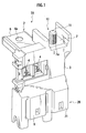
- a fusible link unit 1A is, as shown in Fig. 1, provided with a fuse unit 2, a detail of which is shown in Fig. 2, and a casing 3 partially covering the fuse unit 2.
- a whole shape of the fusible link unit 1A is so dimensioned as to fit a car battery and hence can be directly installed on the battery.
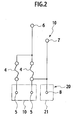
- the fuse unit 2 is provided with a pair of fuse links 4, a pair of load terminals 5, a battery terminal 6, a first alternator terminal 7 and a second alternator terminal 8 as shown in Fig. 2.
- the fuse links 4 are connected in parallel with the respective load terminals 5. Both the first alternator terminal 7 and the second alternator terminal 8 are connected to one of the fuse links 4.
- Each of the fuse links 4 is a piece made of a low-melting metal and configured to melt when a current beyond a respectively predetermined value flows therethrough.
- the fuse links 4 are crimped on respective lines shaped in a narrow cranked shape.
- the load terminals 5 are male contact for connection with the respective load (not shown) and are housed in a connector housing 9 formed at a lower part of the casing 3.
- the battery terminal 6 is provided with a screw hole 6a to which a terminal fitting (not shown) for connection with the battery is connected with a screw (not shown).
- the terminal fitting is further connected to a battery post (not shown) of the battery. Thereby, the battery terminal 6 is connected to the battery without any cable.
- a first alternator input portion 10 is formed of the first alternator terminal 7 and a second alternator input portion 20 is formed of the second alternator terminal 8.
- the first alternator input portion 10 is provided with a screw hole 7a formed on the first alternator terminal 7 and a bolt 11 screwed in the screw hole 7a. Thereby the first alternator input portion 10 is configured to be connectable with an opposite terminal (not shown) of the alternator with a screw.
- the second alternator input portion 20 is provided with the second alternator terminal 8 formed in a male terminal shape connectable with a female connector and are housed in a connector housing 21 formed at a lower part of the casing 3. An opposite terminal (not shown) of the alternator is fixed with the second alternator input portion 20 via the connector.
- the fusible link unit 1A is capable of permitting any of the screw connection and the connector connection and is hence capable of selective permission of high-current and low-current.
- the fusible link unit 1A conducts and distributes electric power supplied by both the battery and the alternator to the respective load via the load terminals 5. In a case where a remaining battery level is short, the battery receives the electric power from the alternator so as to be charged. Provided that overt-current caused by any trouble at the loads flows through any of the fuse links 4, the fuse link 4 melts to shut off the current therethrough and thereby succeeding accidents are prevented beforehand.
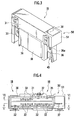
- a fusible link unit 1B is, in contrast with the aforementioned fusible link unit 1A according to the first embodiment, installed separately from the battery as shown in Fig. 3 through 6.
- the fusible link unit 1B is provided with a fuse unit 30 comprised of a busbar press-formed from a conductive sheet and an insulator casing 31 partly covering the fuse unit 30.
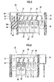
- the fuse unit 30 is provided with a plurality of fuse links 32 and load terminals 33 connected in parallel, a battery terminal 34, a fuse link 35 for the alternator, a first alternator terminal 36 and a second alternator terminal 37, which forms a circuit shown in Fig. 7.
- Each of the fuse links 32 is a piece made of a low-melting metal and configured to melt when a current beyond a respectively predetermined value flows therethrough.
- the fuse links 32 are crimped on respective lines shaped in a narrow cranked shape.
- the load terminals 33 are male contact for connection with the respective load (not shown) and are housed in a connector housing 38 formed at a lower part of the casing 31.
- the battery terminal 34 is provided with a screw hole (not shown) to which a terminal fitting of a cable (not shown) for connection with the battery is connected with a screw (not shown). According to the present embodiment, the battery terminal 34 is connected to the battery via the cable.
- the fuse link 34 for the alternator is also configured to melt when a current beyond a respectively predetermined value flows therethrough.
- the fuse link 34 is crimped on a line shaped in a narrow relatively straight shape.
- a first alternator input portion 40 is formed of the first alternator terminal 36 and a second alternator input portion 50 is formed of the second alternator terminal 37.
- the first alternator input portion 40 is provided with a screw hole 36a formed on the first alternator terminal 36, exposed outward from the casing 31. Thereby the first alternator input portion 40 is configured to be connectable with an opposite terminal (not shown) of the alternator with a screw.
- the second alternator input portion 50 is provided with the second alternator terminal 37 formed in a male terminal shape connectable with a female connector and are housed in a connector housing 51 formed at a lower part of the casing 31.
- An opposite terminal (not shown) of the alternator is fixed with the second alternator input portion 50 via the connector.
- the fusible link unit 1B is capable of permitting any of the screw connection and the connector connection and is hence capable of selective permission of high-current and low-current.
Landscapes
- Fuses (AREA)
Applications Claiming Priority (2)
| Application Number | Priority Date | Filing Date | Title |
|---|---|---|---|
| JP2003428022 | 2003-12-24 | ||
| JP2003428022A JP2005190735A (ja) | 2003-12-24 | 2003-12-24 | ヒュージブルリンクユニット |
Publications (2)
| Publication Number | Publication Date |
|---|---|
| EP1548785A1 true EP1548785A1 (de) | 2005-06-29 |
| EP1548785B1 EP1548785B1 (de) | 2016-02-24 |
Family
ID=34544975
Family Applications (1)
| Application Number | Title | Priority Date | Filing Date |
|---|---|---|---|
| EP04030688.8A Expired - Lifetime EP1548785B1 (de) | 2003-12-24 | 2004-12-23 | Schmelzsicherungsvorrichtung |
Country Status (3)
| Country | Link |
|---|---|
| US (1) | US7420453B2 (de) |
| EP (1) | EP1548785B1 (de) |
| JP (1) | JP2005190735A (de) |
Cited By (2)
| Publication number | Priority date | Publication date | Assignee | Title |
|---|---|---|---|---|
| WO2012120805A1 (en) * | 2011-03-10 | 2012-09-13 | Yazaki Corporation | Fuse unit |
| CN102822933A (zh) * | 2010-04-06 | 2012-12-12 | 矢崎总业株式会社 | 熔丝单元 |
Families Citing this family (33)
| Publication number | Priority date | Publication date | Assignee | Title |
|---|---|---|---|---|
| JP4533827B2 (ja) * | 2005-09-21 | 2010-09-01 | 矢崎総業株式会社 | ヒュージブルリンク |
| JP4769621B2 (ja) * | 2006-04-18 | 2011-09-07 | 住友電装株式会社 | 車載用電気接続箱に収容されるバスバー |
| JP4755018B2 (ja) * | 2006-05-19 | 2011-08-24 | 矢崎総業株式会社 | ヒュージブルリンクユニット |
| DE102006024391A1 (de) * | 2006-05-24 | 2007-11-29 | Lisa Dräxlmaier GmbH | Sicherungseinheit |
| JP4805057B2 (ja) * | 2006-08-04 | 2011-11-02 | 矢崎総業株式会社 | ヒュージブルリンクユニット |
| US7568921B2 (en) * | 2006-08-22 | 2009-08-04 | Lear Corporation | Fuse cassette |
| US20080224814A1 (en) * | 2007-03-13 | 2008-09-18 | Lear Corporation | Electrical assembly and manufacturing method |
| JP4917927B2 (ja) * | 2007-03-15 | 2012-04-18 | 太平洋精工株式会社 | 車両用多連型ヒューズ装置 |
| JP5081549B2 (ja) * | 2007-09-12 | 2012-11-28 | 矢崎総業株式会社 | 端子の接続部構造 |
| US7663466B1 (en) * | 2007-09-21 | 2010-02-16 | Yazaki North America, Inc. | Corner-mounted battery fuse |
| JP5081581B2 (ja) * | 2007-10-30 | 2012-11-28 | 矢崎総業株式会社 | ヒュージブルリンクユニット |
| JP5128902B2 (ja) * | 2007-10-31 | 2013-01-23 | 矢崎総業株式会社 | ヒュージブルリンクユニットの組み付け構造 |
| JP4959507B2 (ja) * | 2007-10-31 | 2012-06-27 | 矢崎総業株式会社 | ヒュージブルリンクユニットの組み付け構造 |
| JP5189920B2 (ja) | 2008-07-25 | 2013-04-24 | 矢崎総業株式会社 | ヒュージブルリンクユニット |
| JP5157765B2 (ja) * | 2008-09-03 | 2013-03-06 | 住友電装株式会社 | 電気接続箱 |
| JP5207533B2 (ja) * | 2008-09-05 | 2013-06-12 | 矢崎総業株式会社 | 複合型ヒュージブルリンク、ヒューズボックス及びその製造方法 |
| JP5334598B2 (ja) * | 2009-01-20 | 2013-11-06 | 矢崎総業株式会社 | ヒューズ |
| JP5277061B2 (ja) * | 2009-04-17 | 2013-08-28 | 矢崎総業株式会社 | ヒュージブルリンクユニット |
| JP5486853B2 (ja) * | 2009-06-29 | 2014-05-07 | 矢崎総業株式会社 | ヒュージブルリンクユニット |
| JP5586241B2 (ja) * | 2010-01-12 | 2014-09-10 | 矢崎総業株式会社 | ヒュージブルリンクユニット |
| JP5547546B2 (ja) * | 2010-04-30 | 2014-07-16 | 矢崎総業株式会社 | 電気接続箱の組立構造 |
| US8669840B2 (en) * | 2010-05-18 | 2014-03-11 | Littelfuse, Inc. | Fuse assembly |
| US8665056B2 (en) | 2010-05-18 | 2014-03-04 | Littlefuse, Inc. | Fuse assembly |
| JP5670769B2 (ja) * | 2011-01-26 | 2015-02-18 | 矢崎総業株式会社 | ヒューズユニット |
| US8808031B2 (en) * | 2011-12-14 | 2014-08-19 | Tyco Electronics Corporation | Battery connector system |
| DE102012011241A1 (de) * | 2012-06-06 | 2013-12-12 | Phoenix Contact Gmbh & Co. Kg | Kontaktelement für einen Varistor |
| JP6063292B2 (ja) * | 2013-02-22 | 2017-01-18 | 矢崎総業株式会社 | ヒュージブルリンク |
| JP6183701B2 (ja) | 2013-08-26 | 2017-08-23 | 住友電装株式会社 | バッテリ直付けヒュージブルリンク |
| JP6175331B2 (ja) * | 2013-09-20 | 2017-08-02 | 矢崎総業株式会社 | ヒューズユニット取付構造 |
| DE102015110171B4 (de) * | 2015-06-24 | 2022-01-20 | Lisa Dräxlmaier GmbH | Elektrische sicherung für ein fahrzeug und damit ausgestatteter elektrischer stromverteiler |
| EP3526805A4 (de) * | 2016-10-12 | 2020-11-25 | Littelfuse, Inc. | Sicherungen mit integrierten metallen |
| US10333129B2 (en) * | 2017-01-26 | 2019-06-25 | Te Connectivity Corporation | Buss bar assembly for a battery system |
| JP6570568B2 (ja) * | 2017-03-14 | 2019-09-04 | 株式会社オートネットワーク技術研究所 | 配線モジュール |
Citations (7)
| Publication number | Priority date | Publication date | Assignee | Title |
|---|---|---|---|---|
| DE29620424U1 (de) * | 1996-11-22 | 1997-01-16 | Lisa Dräxlmaier GmbH, 84137 Vilsbiburg | Stromverteilungsvorrichtung |
| DE19646264A1 (de) * | 1996-11-09 | 1998-05-14 | Wilhelm Pudenz Gmbh Elektrotec | Schmelzleiteraufbau |
| EP0906853A2 (de) * | 1997-10-03 | 1999-04-07 | UT Automotive Dearborn, Inc. | Verbindungskasten montiert auf einer Batterie |
| JP2000182506A (ja) | 1998-12-11 | 2000-06-30 | Taiheiyo Seiko Kk | 多連ヒューズ素子および該多連ヒューズ素子を用いた多連ヒューズ |
| EP1124246A2 (de) | 2000-02-09 | 2001-08-16 | Yazaki Corporation | Sicherungseinheit und Herstellungsverfahren |
| US20030022536A1 (en) * | 2001-07-24 | 2003-01-30 | Sumitomo Wiring Systems, Ltd. | Electrical connection box and method for producing it |
| JP2003320586A (ja) | 2002-04-30 | 2003-11-11 | Jfe Engineering Kk | 電気融着継手用通電制御装置及びコネクター |
Family Cites Families (10)
| Publication number | Priority date | Publication date | Assignee | Title |
|---|---|---|---|---|
| JP2718606B2 (ja) * | 1992-09-04 | 1998-02-25 | 矢崎総業株式会社 | ヒューズボックス |
| US5645448A (en) * | 1995-10-16 | 1997-07-08 | Yazaki Corporation | Battery connecting module with fuse mounting |
| US5643693A (en) * | 1995-10-30 | 1997-07-01 | Yazaki Corporation | Battery-mounted power distribution module |
| US6476705B1 (en) * | 1996-11-22 | 2002-11-05 | Audio Ohm Di Tonani Caterina Ecs.N.C. | Current distribution device |
| GB2326287B (en) * | 1997-06-09 | 2001-10-24 | Delphi Automotive Systems Gmbh | Fuse assembly |
| JP4083991B2 (ja) * | 2000-02-09 | 2008-04-30 | 矢崎総業株式会社 | ヒューズユニットとその製造方法 |
| JP3845266B2 (ja) * | 2001-05-01 | 2006-11-15 | 矢崎総業株式会社 | ヒューズユニット |
| JP3994810B2 (ja) * | 2002-07-09 | 2007-10-24 | 住友電装株式会社 | バッテリーヒューズを内蔵したボックス |
| JP3972197B2 (ja) * | 2002-12-03 | 2007-09-05 | 住友電装株式会社 | バッテリ接続部材 |
| JP4211589B2 (ja) * | 2003-12-02 | 2009-01-21 | 住友電装株式会社 | ヒュージブルリンクおよびヒュージブルリンクを収容したバッテリーヒューズユニット |
-
2003
- 2003-12-24 JP JP2003428022A patent/JP2005190735A/ja active Pending
-
2004
- 2004-12-22 US US11/017,765 patent/US7420453B2/en not_active Expired - Lifetime
- 2004-12-23 EP EP04030688.8A patent/EP1548785B1/de not_active Expired - Lifetime
Patent Citations (7)
| Publication number | Priority date | Publication date | Assignee | Title |
|---|---|---|---|---|
| DE19646264A1 (de) * | 1996-11-09 | 1998-05-14 | Wilhelm Pudenz Gmbh Elektrotec | Schmelzleiteraufbau |
| DE29620424U1 (de) * | 1996-11-22 | 1997-01-16 | Lisa Dräxlmaier GmbH, 84137 Vilsbiburg | Stromverteilungsvorrichtung |
| EP0906853A2 (de) * | 1997-10-03 | 1999-04-07 | UT Automotive Dearborn, Inc. | Verbindungskasten montiert auf einer Batterie |
| JP2000182506A (ja) | 1998-12-11 | 2000-06-30 | Taiheiyo Seiko Kk | 多連ヒューズ素子および該多連ヒューズ素子を用いた多連ヒューズ |
| EP1124246A2 (de) | 2000-02-09 | 2001-08-16 | Yazaki Corporation | Sicherungseinheit und Herstellungsverfahren |
| US20030022536A1 (en) * | 2001-07-24 | 2003-01-30 | Sumitomo Wiring Systems, Ltd. | Electrical connection box and method for producing it |
| JP2003320586A (ja) | 2002-04-30 | 2003-11-11 | Jfe Engineering Kk | 電気融着継手用通電制御装置及びコネクター |
Non-Patent Citations (1)
| Title |
|---|
| PATENT ABSTRACTS OF JAPAN vol. 2000, no. 09 13 October 2000 (2000-10-13) * |
Cited By (7)
| Publication number | Priority date | Publication date | Assignee | Title |
|---|---|---|---|---|
| CN102822933A (zh) * | 2010-04-06 | 2012-12-12 | 矢崎总业株式会社 | 熔丝单元 |
| CN102822933B (zh) * | 2010-04-06 | 2015-04-08 | 矢崎总业株式会社 | 熔丝单元 |
| US9384929B2 (en) | 2010-04-06 | 2016-07-05 | Yazaki Corporation | Fuse unit |
| WO2012120805A1 (en) * | 2011-03-10 | 2012-09-13 | Yazaki Corporation | Fuse unit |
| CN103477413A (zh) * | 2011-03-10 | 2013-12-25 | 矢崎总业株式会社 | 熔丝单元 |
| CN103477413B (zh) * | 2011-03-10 | 2016-09-28 | 矢崎总业株式会社 | 熔丝单元 |
| US9484174B2 (en) | 2011-03-10 | 2016-11-01 | Yazaki Corporation | Fuse unit |
Also Published As
| Publication number | Publication date |
|---|---|
| US20050285709A1 (en) | 2005-12-29 |
| JP2005190735A (ja) | 2005-07-14 |
| EP1548785B1 (de) | 2016-02-24 |
| US7420453B2 (en) | 2008-09-02 |
Similar Documents
| Publication | Publication Date | Title |
|---|---|---|
| US7420453B2 (en) | Fusible link unit | |
| EP1406282B1 (de) | Schmelzsicherungsvorrichtung | |
| US6830482B2 (en) | Fusible link and method of producing said fusible link | |
| CA2428612C (en) | Blade fuse | |
| US20080030295A1 (en) | Fusible Link Unit | |
| US8471670B2 (en) | Fusible link unit | |
| US20130095696A1 (en) | Fuse unit | |
| US20030022536A1 (en) | Electrical connection box and method for producing it | |
| EP1075012A2 (de) | Sicherungsvorrichtung | |
| EP1179453A3 (de) | Anschlusskasten | |
| US20140035717A1 (en) | Fuse | |
| US7108943B2 (en) | Structure of connecting battery terminals to bus bars | |
| KR20150041036A (ko) | 퓨즈 유닛 | |
| KR20150041035A (ko) | 퓨즈 유닛 | |
| JP4009793B2 (ja) | レアショート判断機能付きヒューズ素子、同ヒューズ及び同ヒューズの製造方法 | |
| JP2947079B2 (ja) | 電気接続箱の接続構造 | |
| JP2004127704A (ja) | ヒュージブルリンクユニット | |
| JP3139303B2 (ja) | 電気接続箱の接続構造 | |
| JP4096800B2 (ja) | 自動車用リレーボックス | |
| JPH09283004A (ja) | 電気接続箱 | |
| JP2533901Y2 (ja) | 電気接続箱 | |
| JP2002101526A (ja) | 電気接続箱の電源接続構造 | |
| JPH11185885A (ja) | 過電流保護付ジョイントコネクタ | |
| JP2004186005A (ja) | ヒュージブルリンクユニット | |
| US20070236322A1 (en) | Fuse having connectable terminals |
Legal Events
| Date | Code | Title | Description |
|---|---|---|---|
| PUAI | Public reference made under article 153(3) epc to a published international application that has entered the european phase |
Free format text: ORIGINAL CODE: 0009012 |
|
| 17P | Request for examination filed |
Effective date: 20041223 |
|
| AK | Designated contracting states |
Kind code of ref document: A1 Designated state(s): AT BE BG CH CY CZ DE DK EE ES FI FR GB GR HU IE IS IT LI LT LU MC NL PL PT RO SE SI SK TR |
|
| AX | Request for extension of the european patent |
Extension state: AL BA HR LV MK YU |
|
| AKX | Designation fees paid |
Designated state(s): DE IT |
|
| RAP1 | Party data changed (applicant data changed or rights of an application transferred) |
Owner name: YAZAKI CORPORATION |
|
| 17Q | First examination report despatched |
Effective date: 20120423 |
|
| GRAP | Despatch of communication of intention to grant a patent |
Free format text: ORIGINAL CODE: EPIDOSNIGR1 |
|
| RIC1 | Information provided on ipc code assigned before grant |
Ipc: H01H 85/044 20060101AFI20150903BHEP Ipc: H01H 85/02 20060101ALN20150903BHEP |
|
| INTG | Intention to grant announced |
Effective date: 20150921 |
|
| GRAS | Grant fee paid |
Free format text: ORIGINAL CODE: EPIDOSNIGR3 |
|
| GRAA | (expected) grant |
Free format text: ORIGINAL CODE: 0009210 |
|
| AK | Designated contracting states |
Kind code of ref document: B1 Designated state(s): DE IT |
|
| REG | Reference to a national code |
Ref country code: DE Ref legal event code: R096 Ref document number: 602004048672 Country of ref document: DE |
|
| PG25 | Lapsed in a contracting state [announced via postgrant information from national office to epo] |
Ref country code: IT Free format text: LAPSE BECAUSE OF FAILURE TO SUBMIT A TRANSLATION OF THE DESCRIPTION OR TO PAY THE FEE WITHIN THE PRESCRIBED TIME-LIMIT Effective date: 20160224 |
|
| REG | Reference to a national code |
Ref country code: DE Ref legal event code: R097 Ref document number: 602004048672 Country of ref document: DE |
|
| PLBE | No opposition filed within time limit |
Free format text: ORIGINAL CODE: 0009261 |
|
| STAA | Information on the status of an ep patent application or granted ep patent |
Free format text: STATUS: NO OPPOSITION FILED WITHIN TIME LIMIT |
|
| 26N | No opposition filed |
Effective date: 20161125 |
|
| PGFP | Annual fee paid to national office [announced via postgrant information from national office to epo] |
Ref country code: DE Payment date: 20211102 Year of fee payment: 18 |
|
| REG | Reference to a national code |
Ref country code: DE Ref legal event code: R119 Ref document number: 602004048672 Country of ref document: DE |
|
| PG25 | Lapsed in a contracting state [announced via postgrant information from national office to epo] |
Ref country code: DE Free format text: LAPSE BECAUSE OF NON-PAYMENT OF DUE FEES Effective date: 20230701 |