EP1548735A1 - Aufzeichnungsgerät und Aufzeichnungsverfahren für optische Platten, Informationsaufzeichnungsmedium - Google Patents
Aufzeichnungsgerät und Aufzeichnungsverfahren für optische Platten, Informationsaufzeichnungsmedium Download PDFInfo
- Publication number
- EP1548735A1 EP1548735A1 EP04029081A EP04029081A EP1548735A1 EP 1548735 A1 EP1548735 A1 EP 1548735A1 EP 04029081 A EP04029081 A EP 04029081A EP 04029081 A EP04029081 A EP 04029081A EP 1548735 A1 EP1548735 A1 EP 1548735A1
- Authority
- EP
- European Patent Office
- Prior art keywords
- signal
- phase
- data
- wobble
- vfo
- Prior art date
- Legal status (The legal status is an assumption and is not a legal conclusion. Google has not performed a legal analysis and makes no representation as to the accuracy of the status listed.)
- Withdrawn
Links
- 230000003287 optical effect Effects 0.000 title claims abstract description 41
- 238000000034 method Methods 0.000 title claims description 13
- 230000001360 synchronised effect Effects 0.000 claims description 16
- 238000010586 diagram Methods 0.000 description 18
- 239000008186 active pharmaceutical agent Substances 0.000 description 7
- 230000007423 decrease Effects 0.000 description 3
- 239000000758 substrate Substances 0.000 description 3
- 238000001514 detection method Methods 0.000 description 2
- 238000004519 manufacturing process Methods 0.000 description 2
- 230000010363 phase shift Effects 0.000 description 2
- 230000002950 deficient Effects 0.000 description 1
- 238000000605 extraction Methods 0.000 description 1
Images






Classifications
-
- G—PHYSICS
- G11—INFORMATION STORAGE
- G11B—INFORMATION STORAGE BASED ON RELATIVE MOVEMENT BETWEEN RECORD CARRIER AND TRANSDUCER
- G11B27/00—Editing; Indexing; Addressing; Timing or synchronising; Monitoring; Measuring tape travel
- G11B27/10—Indexing; Addressing; Timing or synchronising; Measuring tape travel
- G11B27/19—Indexing; Addressing; Timing or synchronising; Measuring tape travel by using information detectable on the record carrier
- G11B27/24—Indexing; Addressing; Timing or synchronising; Measuring tape travel by using information detectable on the record carrier by sensing features on the record carrier other than the transducing track ; sensing signals or marks recorded by another method than the main recording
-
- G—PHYSICS
- G11—INFORMATION STORAGE
- G11B—INFORMATION STORAGE BASED ON RELATIVE MOVEMENT BETWEEN RECORD CARRIER AND TRANSDUCER
- G11B7/00—Recording or reproducing by optical means, e.g. recording using a thermal beam of optical radiation by modifying optical properties or the physical structure, reproducing using an optical beam at lower power by sensing optical properties; Record carriers therefor
- G11B7/007—Arrangement of the information on the record carrier, e.g. form of tracks, actual track shape, e.g. wobbled, or cross-section, e.g. v-shaped; Sequential information structures, e.g. sectoring or header formats within a track
-
- G—PHYSICS
- G11—INFORMATION STORAGE
- G11B—INFORMATION STORAGE BASED ON RELATIVE MOVEMENT BETWEEN RECORD CARRIER AND TRANSDUCER
- G11B20/00—Signal processing not specific to the method of recording or reproducing; Circuits therefor
- G11B20/10—Digital recording or reproducing
-
- G—PHYSICS
- G11—INFORMATION STORAGE
- G11B—INFORMATION STORAGE BASED ON RELATIVE MOVEMENT BETWEEN RECORD CARRIER AND TRANSDUCER
- G11B20/00—Signal processing not specific to the method of recording or reproducing; Circuits therefor
- G11B20/10—Digital recording or reproducing
- G11B20/12—Formatting, e.g. arrangement of data block or words on the record carriers
- G11B20/1217—Formatting, e.g. arrangement of data block or words on the record carriers on discs
-
- G—PHYSICS
- G11—INFORMATION STORAGE
- G11B—INFORMATION STORAGE BASED ON RELATIVE MOVEMENT BETWEEN RECORD CARRIER AND TRANSDUCER
- G11B20/00—Signal processing not specific to the method of recording or reproducing; Circuits therefor
- G11B20/10—Digital recording or reproducing
- G11B20/14—Digital recording or reproducing using self-clocking codes
- G11B20/1403—Digital recording or reproducing using self-clocking codes characterised by the use of two levels
-
- G—PHYSICS
- G11—INFORMATION STORAGE
- G11B—INFORMATION STORAGE BASED ON RELATIVE MOVEMENT BETWEEN RECORD CARRIER AND TRANSDUCER
- G11B7/00—Recording or reproducing by optical means, e.g. recording using a thermal beam of optical radiation by modifying optical properties or the physical structure, reproducing using an optical beam at lower power by sensing optical properties; Record carriers therefor
- G11B7/24—Record carriers characterised by shape, structure or physical properties, or by the selection of the material
- G11B7/2407—Tracks or pits; Shape, structure or physical properties thereof
- G11B7/24073—Tracks
- G11B7/24082—Meandering
-
- G—PHYSICS
- G11—INFORMATION STORAGE
- G11B—INFORMATION STORAGE BASED ON RELATIVE MOVEMENT BETWEEN RECORD CARRIER AND TRANSDUCER
- G11B20/00—Signal processing not specific to the method of recording or reproducing; Circuits therefor
- G11B20/10—Digital recording or reproducing
- G11B20/12—Formatting, e.g. arrangement of data block or words on the record carriers
- G11B20/1217—Formatting, e.g. arrangement of data block or words on the record carriers on discs
- G11B2020/1218—Formatting, e.g. arrangement of data block or words on the record carriers on discs wherein the formatting concerns a specific area of the disc
- G11B2020/1238—Formatting, e.g. arrangement of data block or words on the record carriers on discs wherein the formatting concerns a specific area of the disc track, i.e. the entire a spirally or concentrically arranged path on which the recording marks are located
- G11B2020/1239—Formatting, e.g. arrangement of data block or words on the record carriers on discs wherein the formatting concerns a specific area of the disc track, i.e. the entire a spirally or concentrically arranged path on which the recording marks are located the track being a pregroove, e.g. the wobbled track of a recordable optical disc
-
- G—PHYSICS
- G11—INFORMATION STORAGE
- G11B—INFORMATION STORAGE BASED ON RELATIVE MOVEMENT BETWEEN RECORD CARRIER AND TRANSDUCER
- G11B20/00—Signal processing not specific to the method of recording or reproducing; Circuits therefor
- G11B20/10—Digital recording or reproducing
- G11B20/12—Formatting, e.g. arrangement of data block or words on the record carriers
- G11B2020/1264—Formatting, e.g. arrangement of data block or words on the record carriers wherein the formatting concerns a specific kind of data
- G11B2020/1265—Control data, system data or management information, i.e. data used to access or process user data
- G11B2020/1267—Address data
- G11B2020/1269—Absolute time in pregroove [ATIP] information
-
- G—PHYSICS
- G11—INFORMATION STORAGE
- G11B—INFORMATION STORAGE BASED ON RELATIVE MOVEMENT BETWEEN RECORD CARRIER AND TRANSDUCER
- G11B20/00—Signal processing not specific to the method of recording or reproducing; Circuits therefor
- G11B20/10—Digital recording or reproducing
- G11B20/14—Digital recording or reproducing using self-clocking codes
- G11B20/1403—Digital recording or reproducing using self-clocking codes characterised by the use of two levels
- G11B2020/1476—Synchronisation patterns; Coping with defects thereof
-
- G—PHYSICS
- G11—INFORMATION STORAGE
- G11B—INFORMATION STORAGE BASED ON RELATIVE MOVEMENT BETWEEN RECORD CARRIER AND TRANSDUCER
- G11B2220/00—Record carriers by type
- G11B2220/20—Disc-shaped record carriers
- G11B2220/21—Disc-shaped record carriers characterised in that the disc is of read-only, rewritable, or recordable type
- G11B2220/215—Recordable discs
- G11B2220/216—Rewritable discs
-
- G—PHYSICS
- G11—INFORMATION STORAGE
- G11B—INFORMATION STORAGE BASED ON RELATIVE MOVEMENT BETWEEN RECORD CARRIER AND TRANSDUCER
- G11B2220/00—Record carriers by type
- G11B2220/20—Disc-shaped record carriers
- G11B2220/25—Disc-shaped record carriers characterised in that the disc is based on a specific recording technology
- G11B2220/2537—Optical discs
-
- G—PHYSICS
- G11—INFORMATION STORAGE
- G11B—INFORMATION STORAGE BASED ON RELATIVE MOVEMENT BETWEEN RECORD CARRIER AND TRANSDUCER
- G11B2220/00—Record carriers by type
- G11B2220/20—Disc-shaped record carriers
- G11B2220/25—Disc-shaped record carriers characterised in that the disc is based on a specific recording technology
- G11B2220/2537—Optical discs
- G11B2220/2562—DVDs [digital versatile discs]; Digital video discs; MMCDs; HDCDs
-
- G—PHYSICS
- G11—INFORMATION STORAGE
- G11B—INFORMATION STORAGE BASED ON RELATIVE MOVEMENT BETWEEN RECORD CARRIER AND TRANSDUCER
- G11B2220/00—Record carriers by type
- G11B2220/20—Disc-shaped record carriers
- G11B2220/25—Disc-shaped record carriers characterised in that the disc is based on a specific recording technology
- G11B2220/2537—Optical discs
- G11B2220/2562—DVDs [digital versatile discs]; Digital video discs; MMCDs; HDCDs
- G11B2220/2575—DVD-RAMs
Definitions
- the present invention relates to an optical disk on which address information is recorded as wobbles of a recording track, an optical disk apparatus that records and reproduces information on and from the optical disk, and a method of recording information.
- DVD-RAMs and DVD RWs are known as rewritable optical disks. These optical disks have an information recording layer formed on a transparent substrate. Laser light is condensed on the information recording layer to record and reproduce information. Further, as means for recording and reproducing information, the information recording layer of the optical disk has a guide groove often simply called a groove. Information is recorded and reproduced along the guide groove. Furthermore, physical addresses are formed along the guide groove to identify spatial positions at which recording or reproduction of information is carried out.
- a technique called land and groove recording is used as means for increasing density.
- information is recorded both on a groove, which is a concave portion of the guide groove, and on a land, which is a convex portion of the guide groove. This serves to reduce the intervals at which data is recorded in a radial direction, to increase a recording capacity.
- the physical addresses are formed of intermittent concaves and convexes on the substrate called prepits. The guide groove is discontinued in these physical address areas.
- the recording clock frequency is controlled to remove the phase difference.
- jitter may occur in the recording clock, which degrades recording signals.
- An optical disk apparatus comprises: a wobble signal generating section which generates a wobble signal from reflected light from a track in an optical disk on which wobbles modulated by address information are formed; recording clock generating section which multiplies a frequency of the wobble signal to generate a recording clock for information recording; an address phase generating section which generates an address phase signal indicative of a phase of each wobble address, from the wobble signal; a VFO (Variable Frequency Oscillator) signal generating section which generates a VFO signal by dividing a frequency of the recording clock (RCK); a recorded stream generating section which generates a first data stream in synchronism with the phase of the recording clock, from input data and generates, for each predetermined data unit constituting the first data stream, a data phase signal indicative of a phase of the data unit; an inserting section which measures a difference in phase between the address phase signal.
- a wobble signal generating section which generates a wobble signal from reflected light from a track in
- the data phase signal inserts the VFO signal between predetermined amount of the first data streams, to provide a second data stream consisting of the VFO signals and the first data streams, the VFO signal having a length of time corresponding to the difference in phase; and a recording section which records the second data stream on the optical disk.
- the adjustment of an error in recording phase serves to provide an optical disk apparatus that can regulate an error in phase to control the phase of data to be recorded without causing jitter in the recording clock.
- An optical disk on which user information can be recorded has a guide groove in an information area in an information recording layer on a transparent substrate; the guide groove is often simply referred to as a groove.
- the guide groove is called a track.
- Information is recorded and reproduced along the track.
- the track is of a spiral type that extends continuously from inside to outside as shown in FIG. 1.
- the track is of a concentric type formed of a plurality of concentric circles (not shown).
- FIG. 2 is an enlarged diagram of the track.
- the track is formed of concaves and convexes of the information recording layer.
- the concave of the track is called a groove, while the convex of the track is called a land.
- information is formed both on the lands and grooves to increase density in a radial direction.
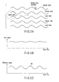
- FIG. 3A is a diagram of the track as viewed from above.
- the track in the optical disk according to the present invention meanders slightly in the radial direction.
- Such a track is called a wobble track.
- a focused beam spot is scanned along the wobble track, the beam spot travels almost straight through the center of the wobble track. This is because a wobble frequency is higher than the band of a tracking servo signal.
- reflected light is received by a photo sensor such as a PD (Photo Diode) 15 shown in FIG. 7, described later; the photo sensor is divided into two pieces in the radial direction.
- PD Photo Diode
- the sum signal remains almost unvaried as shown in FIG. 3B, and only the difference signal varies in accordance with the wobble.
- the difference signal reflects the wobble of the track. Accordingly, the difference signal is called a wobble signal WB in the specification.
- the wobble signal is utilized as a reference for a recording clock or an adjustment signal for the rotation frequency of a spindle.
- modulation of the wobble enables the recording of physical address information indicative of a physical position in the information recording area of the optical disk.
- physical address information is recorded by modulating the frequency or phase of the wobble applied to the track as shown in FIGS. 4A and 4B.
- the signals shown in FIGS. 4A and 4B both show, for example, "1", “0", "1", and "0". Processing of the wobble signal WB enables the extraction of physical address information indicative of a position on the optical disk which is irradiated with a laser beam.
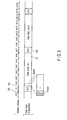
- FIG. 5 is a diagram schematically showing the relationship between the configuration of the data track and wobble addresses.
- Data to be recorded is divided into data blocks 101, each of a predetermined data length.
- the data track on the disk is constructed by inserting VFO (Variable Frequency Oscillator) signals 102 of a predetermined length between the data blocks.
- VFO Very Frequency Oscillator
- the VFO signal is, for example, a continuous clock signal of a period 4T and indicates the start and end of each recording block 101.
- the VFO signal is also used to assist synchronous lead-in in a PLL circuit that generates a clock synchronizing with reproduced data during reproduction.
- Each data block 101 is composed of, for example, 32 sectors each having, for example, 2-kilobyte data and composed of, for example, 26 frames.
- the recording track is composed of the wobble track on which wobble addresses indicative of track positions are recorded in an overlapping manner.
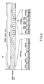
- Each wobble address block 103 shown by a wobble address WADR (m-1, m, m+1, ...) shown in FIG. 5 is configured as shown in FIG. 6.
- One wobble address block 103 constitute one wobble block address.
- the wobble address block 103 is composed of one wobble address block synchronous byte Sync and 16 wobble address byte 104.
- the wobble address block synchronous byte Sync and the 16 wobble address bytes 104 are each composed of 84 wobbles. Accordingly, the wobble address block 103 has 1,428 wobbles.
- IPM denotes a non-modulated wobble signal
- NPW denotes a modulated wobble signal.
- the adjacent IPW and NPW have inverse polarities.
- the wobble address block synchronous byte Sync is composed of 6 IPWs, 4 NPWs, 6 IPWs, and 68 NPWs. One bit is recorded by four wobbles. The NPW indicates "0", and the IPW indicates "1".
- FIG. 7 is a diagram showing an example of the configuration of the optical disk apparatus serving as an information recording apparatus according to the present embodiment.
- FIGS. 8 and 9 are timing charts showing operations of the information recording apparatus shown in FIG. 7.
- an adder 11 adds together two sensing signals provided by the photo sensing elements constituting the respective half surfaces of the PD 10, to generate a reproduced stream signal.
- a subtractor 12 subtracts the smaller sensing signal from the larger sensing signal to generate a wobble signal WB.
- the wobble signal WB is input to a wobble PLL 13 and the wobble address decoder 15.
- the wobble PLL 13 binarizes the wobble signal WB to generate a wobble clock WCK.
- the wobble clock WCK is input to a recording clock multiplying PLL and the wobble address decoder 15.
- the wobble address decoder 15 decodes a wobble address WADR from wobble signal WB using the wobble clock WCK as a reference.
- the wobble address WADR is transmitted to a host apparatus.
- the wobble address WADR is then used as an address on the disk during information recording or reproduction.
- the wobble address decoder 15 detects, for example, the head of each wobble address and outputs a wobble phase reference pulse WPR.
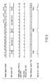
- FIG. 8 shows the waveforms of inputs to and outputs from the wobble address decoder 15.
- the wobble address decoder 15 compares the polarity of the wobble signal WB with the polarity of the wobble clock WCK. If the polarities are the same, the wobble address decoder 15 internally generates a wobble demodulation signal WBD at an "L" level. If the polarities are different from each other, the wobble address decoder 15 internally generates a wobble demodulation signal WBD at an "H” level. Accordingly, the wobble demodulation signal WBD is at the "H" level in the IPW portions.
- the wobble address block synchronous byte (a pattern of 6 IPWs, 4 NPWs, and 6 IPWs) is detected to generate a wobble phase reference pulse WPR.
- the recording clock multiplying PLL 14 multiplies the frequency of the wobble clock WCK by, for example, 93 to generate a recording clock RCK corresponding to a channel frequency.
- the recording clock multiplying PLL 14 converts one wobble into 93 recording clocks RCK.
- the recording clock multiplying PLL 14 includes a VCO (Voltage Controlled Oscillator) 14a.
- the recording clock multiplying PLL 14 varies the frequency of the recording clock RCK in association with a difference in phase between the recording clock RCK and the wobble clock WCK.
- the recording clock multiplying PLL 14 then outputs a recording clock RCK the phase of which synchronizes with the phase of the wobble clock WCK.
- a data block stream generator 17 On the basis of data input by the host apparatus, a data block stream generator 17 generates a data block stream DBS of predetermined amount.
- the channel frequency of the data block stream DBS is obtained using the recording clock RCK as a reference.
- each data (binary signal) of the data block stream DBS is output by the recorded stream generator 17 using the period of the recording clock RCK.
- the data block stream generator 17 detects the sectors or frames (see FIG. 5) in the data sent by the host apparatus.
- the recorded stream generator 17 then outputs data phase reference pulses DPR in synchronism with the recording clock RCK; the data phase reference pulses DPR are indicative of sector synchronous positions or frame synchronous positions.
- the data phase reference pulse DPR indicates the sector synchronous position (for example, the head position of each sector) or the frame synchronous position (for example, the head position of each frame).
- the data block stream DBS is input to a switch 19.
- a VFO signal generated by a VFO pattern generator 18 is also input to the switch 19.
- the VFO signal is obtained by dividing the frequency of the recording clock RCK into, for example, four parts as previously described.
- the wobble phase reference pulse WPR from the wobble address decoder 15 and the data phase reference pulse DPR from the data block stream generator 17 are input to a recording timing controller 16.
- the recording timing controller 16 measures a difference in phase between the signals WPR and DPR input. In FIG. 9, there is no difference in phase between the wobble phase reference pulse WPR and the data phase reference pulse DPR. The amount of difference in phase PDA is thus always 0.
- the recording timing controller 16 On the basis of the wobble phase reference pulse WPR, the data phase reference pulse DPR, and the amount of phase difference PDA, the recording timing controller 16 generates a data selection signal DS.
- the recording timing controller 16 provides the switch 19 with the data selection signal DS.
- the switch 19 selectively outputs a VFO signal when the data selection signal DS is, for example, at the high level.
- the switch 19 selectively outputs a data block stream DBS when the data selection signal DS is, for example, at the low level.
- a data stream DST is generated.
- Laser light is modulated via an LD driver 20. Then, the laser light modulated is used to record the data stream DST on the disk.
- the switch 19 and the recording timing controller 16 constitute a VFO inserting section 21. Accordingly, the VFO inserting section 21 inserts, into a predetermined amount (32 sectors) of data block stream DBS, VFO signals each of a length of time corresponding to the difference in phase between the wobble address phase reference pulse WPR and the data phase reference pulse DPR. As a result, the VFO inserting section 21 provides a data stream DST consisting of the VFO signals and the data block stream DBS.
- FIG. 10 shows that when a data block (n) is generated, the frequency of the recording clock RCK temporarily increases for some reason. Desirably, the data terminal of the data block (n) intrinsically coincides with the terminal of the wobble address (m+6). However, in FIG. 10, the recording of the data block (n) ends prematurely.
- a wobble formed during the manufacture of a disk is defective or the disk is damaged or stained during manufacture, a normal wobble signal WB is not obtained.
- the wobble clock WCK from the wobble PLL 13 is instable.
- an input voltage to the VCO 14a of the recording clock multiplying PLL 14 is instable. This may change the frequency of the recording clock RCK.
- the period of the recording clock RCK changes, the period of the data phase reference pulse DPR also changes. For example, a decrease in the period of the recording clock RCK reduces the period of the data phase reference pulse DPR.
- the wobble phase reference pulse WPR is generally not disturbed as shown in FIG. 10. This is because a wobble phase reference pulse WPR is normally generated from the wobble track formed on the disk provided that the first 16 wobbles (6 IPWs, 4 NPWs, and 6 IPWs) of a wobble address block synchronous byte Sync (see FIG. 6) in the wobble address block 103 as well as wobbles preceding and succeeding these 16 wobbles are normally detected.
- phase of the data phase reference pulse DPR (sector synchronous position or frame synchronous position) shifts from the phase of the wobble phase reference pulse WPR.
- the recording timing controller 16 measures the amount of phase shift (phase difference).
- the recording timing controller 16 controls the switch 19 so that the corresponding VFO signal recorded area is extended in association with the phase difference.
- a data block (n+1) starts to be recorded at the head of the wobble address (m+8).
- the phase is 40 recording clocks RCK faster. Accordingly, the VFO is extended by a length equal to 40 clocks.
- FIG. 11 is a diagram showing that when a data block (n) is generated, the frequency of the recording clock RCK temporarily decreases because of, for example, the disturbance of a wobble signal.
- the data terminal of the data block (n) intrinsically coincides with the terminal of the wobble address (m+6).
- the recording of the data block (n) ends later than desired.
- the recording timing controller 16 measures the amount of phase shift (phase difference).
- the recording timing controller 16 controls the switch 19 so that the corresponding VFO signal recorded area is shortened in association with the phase difference.
- the data block (n+1) starts to be recorded at the head of the wobble address (m+8).
- the phase is slower by 80 recording clock RCK. Accordingly, the VFO is shortened by a length equal to 80 clocks.
- the position can be corrected without any increase in the amount of recording clock jitter.
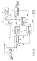
- FIG. 12 is a diagram showing an example of the configuration of an essential part of an optical disk apparatus according to a second embodiment of the present invention.
- the VFO inserting section 21 is composed of an OR circuit 22 and the recording timing controller 16.
- the VFO pattern generator 18 and the data block stream generator 17 are supplied with a data selection signal DS output by the recording timing controller 16.
- the data selection signal DS is at, for example, the high level
- the data block stream generator 17 outputs a data block stream DBS.
- the VFO pattern generator 18 outputs a VFO signal.
- the OR circuit 22 outputs the logical OR of the data block stream DBS and VFO signal to the LD 20.
- the switch 19 is replaced with the OR circuit 22. This makes it possible to simplify the configuration of the circuit.
- the present invention includes apparatuses and methods configured by appropriately combining any of the components, functions, features, or process steps of the embodiments.
Landscapes
- Engineering & Computer Science (AREA)
- Signal Processing (AREA)
- Optical Recording Or Reproduction (AREA)
- Signal Processing For Digital Recording And Reproducing (AREA)
Applications Claiming Priority (2)
| Application Number | Priority Date | Filing Date | Title |
|---|---|---|---|
| JP2003431032A JP2005190583A (ja) | 2003-12-25 | 2003-12-25 | 光ディスク装置、情報記録方法及び情報記録媒体 |
| JP2003431032 | 2003-12-25 |
Publications (1)
| Publication Number | Publication Date |
|---|---|
| EP1548735A1 true EP1548735A1 (de) | 2005-06-29 |
Family
ID=34545040
Family Applications (1)
| Application Number | Title | Priority Date | Filing Date |
|---|---|---|---|
| EP04029081A Withdrawn EP1548735A1 (de) | 2003-12-25 | 2004-12-08 | Aufzeichnungsgerät und Aufzeichnungsverfahren für optische Platten, Informationsaufzeichnungsmedium |
Country Status (6)
| Country | Link |
|---|---|
| US (1) | US7397751B2 (de) |
| EP (1) | EP1548735A1 (de) |
| JP (1) | JP2005190583A (de) |
| KR (1) | KR100682364B1 (de) |
| CN (1) | CN1299266C (de) |
| TW (1) | TW200534251A (de) |
Families Citing this family (7)
| Publication number | Priority date | Publication date | Assignee | Title |
|---|---|---|---|---|
| KR20050036228A (ko) * | 2003-10-15 | 2005-04-20 | 삼성전자주식회사 | 멀티미디어 재생을 관리하는 장치 및 방법 |
| US20070127343A1 (en) * | 2005-12-05 | 2007-06-07 | Wei-Hsiang Tseng | Information recording device and related method |
| US7816921B2 (en) * | 2006-09-20 | 2010-10-19 | Baker Hughes Incorporated | Resistivity tools with load-bearing azimuthally sensitive antennas and methods of using same |
| US7663372B2 (en) * | 2006-09-25 | 2010-02-16 | Baker Hughes Incorporated | Resistivity tools with collocated antennas |
| JP2009032306A (ja) * | 2007-07-24 | 2009-02-12 | Hitachi Ltd | 光ディスクへの情報記録再生方法及びその装置 |
| JP2012059343A (ja) * | 2010-09-13 | 2012-03-22 | Sony Corp | 記録装置 |
| US8830616B2 (en) * | 2011-12-05 | 2014-09-09 | Varian Semiconductor Equipment Associates, Inc. | Magnetic storage device |
Citations (3)
| Publication number | Priority date | Publication date | Assignee | Title |
|---|---|---|---|---|
| US6172947B1 (en) * | 1996-10-23 | 2001-01-09 | Sony Corporation | Method and apparatus for time shifted signal recording and reproduction |
| EP1098301A2 (de) * | 1999-11-03 | 2001-05-09 | Samsung Electronics Co., Ltd. | Adressierungsverfahren für physikalische Identifikationsdaten das gewobbelte Signale nutzt, Schaltung zur Kodierung von Wobbeladressen, Verfahren und Schaltung zur Detektion von Wobbeladressen, und Aufzeichnungsmedium |
| JP2002032962A (ja) * | 2000-07-13 | 2002-01-31 | Matsushita Electric Ind Co Ltd | クロック信号発生装置 |
Family Cites Families (5)
| Publication number | Priority date | Publication date | Assignee | Title |
|---|---|---|---|---|
| JP2606509B2 (ja) * | 1991-11-28 | 1997-05-07 | 松下電器産業株式会社 | 光ディスク装置 |
| CN1193350C (zh) * | 1999-11-03 | 2005-03-16 | 三星电子株式会社 | 标识数据寻址方法、摆动地址编码电路及检测方法和电路 |
| JP2003059050A (ja) | 2001-08-20 | 2003-02-28 | Matsushita Electric Ind Co Ltd | 光ディスク記録方法 |
| JP3561259B2 (ja) * | 2002-01-09 | 2004-09-02 | 株式会社東芝 | 情報記憶媒体、情報記録装置、情報再生装置、情報記録方法、及び情報再生方法 |
| JP2003233914A (ja) * | 2002-02-06 | 2003-08-22 | Hitachi-Lg Data Storage Inc | フォーカスオフセット設定方法およびそれを用いた光ディスク装置 |
-
2003
- 2003-12-25 JP JP2003431032A patent/JP2005190583A/ja active Pending
-
2004
- 2004-12-08 EP EP04029081A patent/EP1548735A1/de not_active Withdrawn
- 2004-12-20 TW TW093139663A patent/TW200534251A/zh unknown
- 2004-12-22 US US11/017,703 patent/US7397751B2/en not_active Expired - Fee Related
- 2004-12-24 CN CNB2004100114954A patent/CN1299266C/zh not_active Expired - Fee Related
- 2004-12-24 KR KR1020040112565A patent/KR100682364B1/ko not_active Expired - Fee Related
Patent Citations (3)
| Publication number | Priority date | Publication date | Assignee | Title |
|---|---|---|---|---|
| US6172947B1 (en) * | 1996-10-23 | 2001-01-09 | Sony Corporation | Method and apparatus for time shifted signal recording and reproduction |
| EP1098301A2 (de) * | 1999-11-03 | 2001-05-09 | Samsung Electronics Co., Ltd. | Adressierungsverfahren für physikalische Identifikationsdaten das gewobbelte Signale nutzt, Schaltung zur Kodierung von Wobbeladressen, Verfahren und Schaltung zur Detektion von Wobbeladressen, und Aufzeichnungsmedium |
| JP2002032962A (ja) * | 2000-07-13 | 2002-01-31 | Matsushita Electric Ind Co Ltd | クロック信号発生装置 |
Non-Patent Citations (1)
| Title |
|---|
| PATENT ABSTRACTS OF JAPAN vol. 2002, no. 05 3 May 2002 (2002-05-03) * |
Also Published As
| Publication number | Publication date |
|---|---|
| US20050141373A1 (en) | 2005-06-30 |
| US7397751B2 (en) | 2008-07-08 |
| KR20050065438A (ko) | 2005-06-29 |
| CN1299266C (zh) | 2007-02-07 |
| KR100682364B1 (ko) | 2007-02-15 |
| CN1637872A (zh) | 2005-07-13 |
| JP2005190583A (ja) | 2005-07-14 |
| TW200534251A (en) | 2005-10-16 |
Similar Documents
| Publication | Publication Date | Title |
|---|---|---|
| US6522608B1 (en) | Information recording apparatus for writable recording media | |
| JP4102483B2 (ja) | 情報記録装置 | |
| JP3542553B2 (ja) | ウォッブル信号を用いたpidアドレッシング方法とその検出方法、ウォッブルアドレスエンコーディング回路とその検出回路及び記録媒体 | |
| JP3937134B2 (ja) | 多重変調されたヘッダ信号が記録された光記録媒体、そのヘッダ信号記録方法、記録装置、再生方法及び再生装置 | |
| JP3850600B2 (ja) | 情報記録ディスクおよび情報記録装置 | |
| EP0871169A1 (de) | Vorrichtung zur Feststellung von vorausgehenden Pits und Informationsaufzeichnungsgerät damit | |
| JP4091575B2 (ja) | ウォッブルアドレス検出方法及び回路 | |
| CN100409325C (zh) | 光记录介质及其制造方法 | |
| US7397751B2 (en) | Optical disk apparatus, method of recording information, and information recording medium | |
| JP3881835B2 (ja) | 記録再生装置 | |
| JP3961338B2 (ja) | 光ディスク装置 | |
| JP3714117B2 (ja) | プリピット検出装置、プリピット検出方法、位置及び周波数信号の検出回路 | |
| JP4200077B2 (ja) | 情報記録装置、情報記録方法、及び情報記録プログラム | |
| JP3753169B2 (ja) | 情報記録装置および情報記録方法 | |
| JP3888067B2 (ja) | クロック生成回路及びそれを用いた記録再生装置 | |
| JP4267901B2 (ja) | 再生方法および装置 | |
| RU2262141C2 (ru) | Оптический диск и формат физического адреса | |
| JPH11288518A (ja) | 光ディスク、光ディスク記録再生装置、光ディスク記録再生方法、光ディスク原盤製造装置 | |
| JP3933662B2 (ja) | 移動制御情報記録装置及び移動制御情報記録方法 | |
| US20060098564A1 (en) | Information recording medium, information recording and reproducing apparatus and method for adjusting phase of recording track | |
| JP2003115114A (ja) | 光ディスク媒体、光ディスク装置および光ディスク再生方法 | |
| JP2003045039A (ja) | 光情報記録媒体、光情報記録媒体記録方法、光情報記録媒体再生方法、光情報記録媒体記録装置、光情報記録媒体再生装置 | |
| JP2004319089A (ja) | プリピット検出装置、プリピット検出方法 | |
| JP2005196968A (ja) | 情報記録ディスクおよび情報記録ディスク再生装置 | |
| JP2002352442A (ja) | 光ディスク、光ディスク記録方法、光ディスク装置 |
Legal Events
| Date | Code | Title | Description |
|---|---|---|---|
| PUAI | Public reference made under article 153(3) epc to a published international application that has entered the european phase |
Free format text: ORIGINAL CODE: 0009012 |
|
| 17P | Request for examination filed |
Effective date: 20041208 |
|
| AK | Designated contracting states |
Kind code of ref document: A1 Designated state(s): AT BE BG CH CY CZ DE DK EE ES FI FR GB GR HU IE IS IT LI LT LU MC NL PL PT RO SE SI SK TR |
|
| AX | Request for extension of the european patent |
Extension state: AL BA HR LV MK YU |
|
| AKX | Designation fees paid |
Designated state(s): DE FR GB |
|
| STAA | Information on the status of an ep patent application or granted ep patent |
Free format text: STATUS: THE APPLICATION IS DEEMED TO BE WITHDRAWN |
|
| 18D | Application deemed to be withdrawn |
Effective date: 20100630 |