EP1548427B1 - Biosensor and method for manufacturing same - Google Patents
Biosensor and method for manufacturing same Download PDFInfo
- Publication number
- EP1548427B1 EP1548427B1 EP03788056A EP03788056A EP1548427B1 EP 1548427 B1 EP1548427 B1 EP 1548427B1 EP 03788056 A EP03788056 A EP 03788056A EP 03788056 A EP03788056 A EP 03788056A EP 1548427 B1 EP1548427 B1 EP 1548427B1
- Authority
- EP
- European Patent Office
- Prior art keywords
- biosensor
- reaction part
- electrode
- sheet
- sample
- Prior art date
- Legal status (The legal status is an assumption and is not a legal conclusion. Google has not performed a legal analysis and makes no representation as to the accuracy of the status listed.)
- Expired - Lifetime
Links
- 238000000034 method Methods 0.000 title abstract description 56
- 238000004519 manufacturing process Methods 0.000 title abstract description 31
- 238000006243 chemical reaction Methods 0.000 claims abstract description 166
- 239000000758 substrate Substances 0.000 claims abstract description 67
- 108090000854 Oxidoreductases Proteins 0.000 claims abstract description 27
- 102000004316 Oxidoreductases Human genes 0.000 claims abstract description 27
- 239000007788 liquid Substances 0.000 claims description 67
- 125000006850 spacer group Chemical group 0.000 claims description 33
- 230000009471 action Effects 0.000 claims description 7
- 238000006911 enzymatic reaction Methods 0.000 claims description 5
- 230000008859 change Effects 0.000 claims description 4
- 229920001477 hydrophilic polymer Polymers 0.000 abstract description 35
- 230000002209 hydrophobic effect Effects 0.000 abstract description 11
- 238000003860 storage Methods 0.000 abstract description 11
- UFHFLCQGNIYNRP-UHFFFAOYSA-N Hydrogen Chemical compound [H][H] UFHFLCQGNIYNRP-UHFFFAOYSA-N 0.000 abstract description 8
- 238000004445 quantitative analysis Methods 0.000 abstract description 5
- 239000000523 sample Substances 0.000 description 66
- 239000010408 film Substances 0.000 description 40
- 239000002904 solvent Substances 0.000 description 37
- 238000005259 measurement Methods 0.000 description 36
- 239000000370 acceptor Substances 0.000 description 32
- 239000001913 cellulose Substances 0.000 description 31
- 229920002678 cellulose Polymers 0.000 description 31
- BASFCYQUMIYNBI-UHFFFAOYSA-N platinum Chemical compound [Pt] BASFCYQUMIYNBI-UHFFFAOYSA-N 0.000 description 28
- 239000011259 mixed solution Substances 0.000 description 24
- 102000004190 Enzymes Human genes 0.000 description 22
- 108090000790 Enzymes Proteins 0.000 description 22
- 229940088598 enzyme Drugs 0.000 description 22
- -1 potassium ferricyanides Chemical class 0.000 description 21
- 239000006185 dispersion Substances 0.000 description 20
- XLYOFNOQVPJJNP-UHFFFAOYSA-N water Substances O XLYOFNOQVPJJNP-UHFFFAOYSA-N 0.000 description 20
- 210000004027 cell Anatomy 0.000 description 19
- 230000000052 comparative effect Effects 0.000 description 18
- 229920001721 polyimide Polymers 0.000 description 18
- 238000004544 sputter deposition Methods 0.000 description 17
- 229920000642 polymer Polymers 0.000 description 15
- 239000000243 solution Substances 0.000 description 15
- 125000005702 oxyalkylene group Chemical group 0.000 description 14
- 229910052697 platinum Inorganic materials 0.000 description 14
- WQZGKKKJIJFFOK-GASJEMHNSA-N Glucose Natural products OC[C@H]1OC(O)[C@H](O)[C@@H](O)[C@@H]1O WQZGKKKJIJFFOK-GASJEMHNSA-N 0.000 description 13
- 239000008103 glucose Substances 0.000 description 13
- 239000002245 particle Substances 0.000 description 12
- 238000003756 stirring Methods 0.000 description 12
- 239000000725 suspension Substances 0.000 description 12
- 125000000217 alkyl group Chemical group 0.000 description 11
- 239000004020 conductor Substances 0.000 description 11
- JVTAAEKCZFNVCJ-UHFFFAOYSA-N lactic acid Chemical compound CC(O)C(O)=O JVTAAEKCZFNVCJ-UHFFFAOYSA-N 0.000 description 11
- 229920002799 BoPET Polymers 0.000 description 10
- 238000001035 drying Methods 0.000 description 10
- 230000008569 process Effects 0.000 description 10
- 239000012488 sample solution Substances 0.000 description 10
- 239000000853 adhesive Substances 0.000 description 9
- 230000001070 adhesive effect Effects 0.000 description 9
- 239000000203 mixture Substances 0.000 description 9
- KDLHZDBZIXYQEI-UHFFFAOYSA-N Palladium Chemical compound [Pd] KDLHZDBZIXYQEI-UHFFFAOYSA-N 0.000 description 8
- 239000010410 layer Substances 0.000 description 8
- 239000004642 Polyimide Substances 0.000 description 7
- 230000015572 biosynthetic process Effects 0.000 description 7
- 229920001225 polyester resin Polymers 0.000 description 7
- ZNQVEEAIQZEUHB-UHFFFAOYSA-N 2-ethoxyethanol Chemical compound CCOCCO ZNQVEEAIQZEUHB-UHFFFAOYSA-N 0.000 description 6
- LFQSCWFLJHTTHZ-UHFFFAOYSA-N Ethanol Chemical compound CCO LFQSCWFLJHTTHZ-UHFFFAOYSA-N 0.000 description 6
- 239000013078 crystal Substances 0.000 description 6
- 230000000694 effects Effects 0.000 description 6
- 235000014655 lactic acid Nutrition 0.000 description 6
- 239000004310 lactic acid Substances 0.000 description 6
- 239000000463 material Substances 0.000 description 6
- 229920000139 polyethylene terephthalate Polymers 0.000 description 6
- 239000005020 polyethylene terephthalate Substances 0.000 description 6
- 238000012360 testing method Methods 0.000 description 6
- 108010015776 Glucose oxidase Proteins 0.000 description 5
- 239000004366 Glucose oxidase Substances 0.000 description 5
- 239000006071 cream Substances 0.000 description 5
- LYCAIKOWRPUZTN-UHFFFAOYSA-N ethylene glycol Natural products OCCO LYCAIKOWRPUZTN-UHFFFAOYSA-N 0.000 description 5
- 229940116332 glucose oxidase Drugs 0.000 description 5
- 235000019420 glucose oxidase Nutrition 0.000 description 5
- 230000035945 sensitivity Effects 0.000 description 5
- LEHOTFFKMJEONL-UHFFFAOYSA-N Uric Acid Chemical compound N1C(=O)NC(=O)C2=C1NC(=O)N2 LEHOTFFKMJEONL-UHFFFAOYSA-N 0.000 description 4
- TVWHNULVHGKJHS-UHFFFAOYSA-N Uric acid Natural products N1C(=O)NC(=O)C2NC(=O)NC21 TVWHNULVHGKJHS-UHFFFAOYSA-N 0.000 description 4
- 125000001931 aliphatic group Chemical group 0.000 description 4
- 125000003118 aryl group Chemical group 0.000 description 4
- 239000003153 chemical reaction reagent Substances 0.000 description 4
- 238000000151 deposition Methods 0.000 description 4
- 239000012777 electrically insulating material Substances 0.000 description 4
- 239000007789 gas Substances 0.000 description 4
- PCHJSUWPFVWCPO-UHFFFAOYSA-N gold Chemical compound [Au] PCHJSUWPFVWCPO-UHFFFAOYSA-N 0.000 description 4
- 239000010931 gold Substances 0.000 description 4
- 229910052737 gold Inorganic materials 0.000 description 4
- AMGQUBHHOARCQH-UHFFFAOYSA-N indium;oxotin Chemical class [In].[Sn]=O AMGQUBHHOARCQH-UHFFFAOYSA-N 0.000 description 4
- 238000010030 laminating Methods 0.000 description 4
- 230000000873 masking effect Effects 0.000 description 4
- 229910052763 palladium Inorganic materials 0.000 description 4
- 239000000843 powder Substances 0.000 description 4
- 238000001556 precipitation Methods 0.000 description 4
- 239000000126 substance Substances 0.000 description 4
- 229940116269 uric acid Drugs 0.000 description 4
- RTZKZFJDLAIYFH-UHFFFAOYSA-N Diethyl ether Chemical compound CCOCC RTZKZFJDLAIYFH-UHFFFAOYSA-N 0.000 description 3
- IAYPIBMASNFSPL-UHFFFAOYSA-N Ethylene oxide Chemical compound C1CO1 IAYPIBMASNFSPL-UHFFFAOYSA-N 0.000 description 3
- KFZMGEQAYNKOFK-UHFFFAOYSA-N Isopropanol Chemical compound CC(C)O KFZMGEQAYNKOFK-UHFFFAOYSA-N 0.000 description 3
- OKKJLVBELUTLKV-UHFFFAOYSA-N Methanol Chemical compound OC OKKJLVBELUTLKV-UHFFFAOYSA-N 0.000 description 3
- 229910052783 alkali metal Inorganic materials 0.000 description 3
- 239000007900 aqueous suspension Substances 0.000 description 3
- 239000002585 base Substances 0.000 description 3
- 210000004369 blood Anatomy 0.000 description 3
- 239000008280 blood Substances 0.000 description 3
- 150000001875 compounds Chemical class 0.000 description 3
- 238000001514 detection method Methods 0.000 description 3
- 238000007599 discharging Methods 0.000 description 3
- 238000004090 dissolution Methods 0.000 description 3
- 239000012153 distilled water Substances 0.000 description 3
- 239000005038 ethylene vinyl acetate Substances 0.000 description 3
- 239000010419 fine particle Substances 0.000 description 3
- 125000002887 hydroxy group Chemical group [H]O* 0.000 description 3
- 230000001976 improved effect Effects 0.000 description 3
- 239000012528 membrane Substances 0.000 description 3
- 238000001259 photo etching Methods 0.000 description 3
- 239000000049 pigment Substances 0.000 description 3
- 238000002360 preparation method Methods 0.000 description 3
- 230000009257 reactivity Effects 0.000 description 3
- 150000005846 sugar alcohols Polymers 0.000 description 3
- 238000001771 vacuum deposition Methods 0.000 description 3
- 230000003245 working effect Effects 0.000 description 3
- AZQWKYJCGOJGHM-UHFFFAOYSA-N 1,4-benzoquinone Chemical compound O=C1C=CC(=O)C=C1 AZQWKYJCGOJGHM-UHFFFAOYSA-N 0.000 description 2
- VZSRBBMJRBPUNF-UHFFFAOYSA-N 2-(2,3-dihydro-1H-inden-2-ylamino)-N-[3-oxo-3-(2,4,6,7-tetrahydrotriazolo[4,5-c]pyridin-5-yl)propyl]pyrimidine-5-carboxamide Chemical compound C1C(CC2=CC=CC=C12)NC1=NC=C(C=N1)C(=O)NCCC(N1CC2=C(CC1)NN=N2)=O VZSRBBMJRBPUNF-UHFFFAOYSA-N 0.000 description 2
- RGHNJXZEOKUKBD-SQOUGZDYSA-N D-gluconic acid Chemical compound OC[C@@H](O)[C@@H](O)[C@H](O)[C@@H](O)C(O)=O RGHNJXZEOKUKBD-SQOUGZDYSA-N 0.000 description 2
- MHAJPDPJQMAIIY-UHFFFAOYSA-N Hydrogen peroxide Chemical compound OO MHAJPDPJQMAIIY-UHFFFAOYSA-N 0.000 description 2
- LRHPLDYGYMQRHN-UHFFFAOYSA-N N-Butanol Chemical compound CCCCO LRHPLDYGYMQRHN-UHFFFAOYSA-N 0.000 description 2
- GOOHAUXETOMSMM-UHFFFAOYSA-N Propylene oxide Chemical compound CC1CO1 GOOHAUXETOMSMM-UHFFFAOYSA-N 0.000 description 2
- 229920002125 Sokalan® Polymers 0.000 description 2
- 239000012790 adhesive layer Substances 0.000 description 2
- 230000002411 adverse Effects 0.000 description 2
- 150000001298 alcohols Chemical class 0.000 description 2
- 150000001340 alkali metals Chemical class 0.000 description 2
- 125000002947 alkylene group Chemical group 0.000 description 2
- 239000007864 aqueous solution Substances 0.000 description 2
- DQXBYHZEEUGOBF-UHFFFAOYSA-N but-3-enoic acid;ethene Chemical compound C=C.OC(=O)CC=C DQXBYHZEEUGOBF-UHFFFAOYSA-N 0.000 description 2
- 239000011248 coating agent Substances 0.000 description 2
- 238000000576 coating method Methods 0.000 description 2
- 238000010586 diagram Methods 0.000 description 2
- 239000003085 diluting agent Substances 0.000 description 2
- KTWOOEGAPBSYNW-UHFFFAOYSA-N ferrocene Chemical compound [Fe+2].C=1C=C[CH-]C=1.C=1C=C[CH-]C=1 KTWOOEGAPBSYNW-UHFFFAOYSA-N 0.000 description 2
- WGCNASOHLSPBMP-UHFFFAOYSA-N hydroxyacetaldehyde Natural products OCC=O WGCNASOHLSPBMP-UHFFFAOYSA-N 0.000 description 2
- 239000000178 monomer Substances 0.000 description 2
- 230000033116 oxidation-reduction process Effects 0.000 description 2
- 229920003023 plastic Polymers 0.000 description 2
- 239000004033 plastic Substances 0.000 description 2
- 239000002985 plastic film Substances 0.000 description 2
- 229920006255 plastic film Polymers 0.000 description 2
- 229920001200 poly(ethylene-vinyl acetate) Polymers 0.000 description 2
- 238000007142 ring opening reaction Methods 0.000 description 2
- 230000008093 supporting effect Effects 0.000 description 2
- AWDBHOZBRXWRKS-UHFFFAOYSA-N tetrapotassium;iron(6+);hexacyanide Chemical compound [K+].[K+].[K+].[K+].[Fe+6].N#[C-].N#[C-].N#[C-].N#[C-].N#[C-].N#[C-] AWDBHOZBRXWRKS-UHFFFAOYSA-N 0.000 description 2
- DNIAPMSPPWPWGF-GSVOUGTGSA-N (R)-(-)-Propylene glycol Chemical compound C[C@@H](O)CO DNIAPMSPPWPWGF-GSVOUGTGSA-N 0.000 description 1
- RBACIKXCRWGCBB-UHFFFAOYSA-N 1,2-Epoxybutane Chemical compound CCC1CO1 RBACIKXCRWGCBB-UHFFFAOYSA-N 0.000 description 1
- RYHBNJHYFVUHQT-UHFFFAOYSA-N 1,4-Dioxane Chemical compound C1COCCO1 RYHBNJHYFVUHQT-UHFFFAOYSA-N 0.000 description 1
- IAGVANYWTGRDOU-UHFFFAOYSA-N 1,4-dioxonaphthalene-2-sulfonic acid Chemical compound C1=CC=C2C(=O)C(S(=O)(=O)O)=CC(=O)C2=C1 IAGVANYWTGRDOU-UHFFFAOYSA-N 0.000 description 1
- CCBICDLNWJRFPO-UHFFFAOYSA-N 2,6-dichloroindophenol Chemical compound C1=CC(O)=CC=C1N=C1C=C(Cl)C(=O)C(Cl)=C1 CCBICDLNWJRFPO-UHFFFAOYSA-N 0.000 description 1
- RXGJTUSBYWCRBK-UHFFFAOYSA-M 5-methylphenazinium methyl sulfate Chemical compound COS([O-])(=O)=O.C1=CC=C2[N+](C)=C(C=CC=C3)C3=NC2=C1 RXGJTUSBYWCRBK-UHFFFAOYSA-M 0.000 description 1
- 102000007698 Alcohol dehydrogenase Human genes 0.000 description 1
- 108010021809 Alcohol dehydrogenase Proteins 0.000 description 1
- 108010025188 Alcohol oxidase Proteins 0.000 description 1
- RGHNJXZEOKUKBD-UHFFFAOYSA-N D-gluconic acid Natural products OCC(O)C(O)C(O)C(O)C(O)=O RGHNJXZEOKUKBD-UHFFFAOYSA-N 0.000 description 1
- PHOQVHQSTUBQQK-SQOUGZDYSA-N D-glucono-1,5-lactone Chemical compound OC[C@H]1OC(=O)[C@H](O)[C@@H](O)[C@@H]1O PHOQVHQSTUBQQK-SQOUGZDYSA-N 0.000 description 1
- 101710088194 Dehydrogenase Proteins 0.000 description 1
- 239000004831 Hot glue Substances 0.000 description 1
- 239000004962 Polyamide-imide Substances 0.000 description 1
- 239000002202 Polyethylene glycol Substances 0.000 description 1
- ZLMJMSJWJFRBEC-UHFFFAOYSA-N Potassium Chemical class [K] ZLMJMSJWJFRBEC-UHFFFAOYSA-N 0.000 description 1
- WYURNTSHIVDZCO-UHFFFAOYSA-N Tetrahydrofuran Chemical compound C1CCOC1 WYURNTSHIVDZCO-UHFFFAOYSA-N 0.000 description 1
- GWEVSGVZZGPLCZ-UHFFFAOYSA-N Titan oxide Chemical compound O=[Ti]=O GWEVSGVZZGPLCZ-UHFFFAOYSA-N 0.000 description 1
- 108010092464 Urate Oxidase Proteins 0.000 description 1
- 239000003125 aqueous solvent Substances 0.000 description 1
- 239000012300 argon atmosphere Substances 0.000 description 1
- QVGXLLKOCUKJST-UHFFFAOYSA-N atomic oxygen Chemical compound [O] QVGXLLKOCUKJST-UHFFFAOYSA-N 0.000 description 1
- 229920000229 biodegradable polyester Polymers 0.000 description 1
- 239000004622 biodegradable polyester Substances 0.000 description 1
- 210000000601 blood cell Anatomy 0.000 description 1
- 238000009835 boiling Methods 0.000 description 1
- 125000004432 carbon atom Chemical group C* 0.000 description 1
- 239000000919 ceramic Substances 0.000 description 1
- 239000000470 constituent Substances 0.000 description 1
- 230000006837 decompression Effects 0.000 description 1
- 239000002274 desiccant Substances 0.000 description 1
- 235000014113 dietary fatty acids Nutrition 0.000 description 1
- 238000007865 diluting Methods 0.000 description 1
- 238000003487 electrochemical reaction Methods 0.000 description 1
- DQYBDCGIPTYXML-UHFFFAOYSA-N ethoxyethane;hydrate Chemical compound O.CCOCC DQYBDCGIPTYXML-UHFFFAOYSA-N 0.000 description 1
- 238000002474 experimental method Methods 0.000 description 1
- 239000000194 fatty acid Substances 0.000 description 1
- 229930195729 fatty acid Natural products 0.000 description 1
- 230000002349 favourable effect Effects 0.000 description 1
- 239000000835 fiber Substances 0.000 description 1
- 239000012634 fragment Substances 0.000 description 1
- 239000000174 gluconic acid Substances 0.000 description 1
- 235000012208 gluconic acid Nutrition 0.000 description 1
- 235000012209 glucono delta-lactone Nutrition 0.000 description 1
- 229960003681 gluconolactone Drugs 0.000 description 1
- 239000012943 hotmelt Substances 0.000 description 1
- 239000004615 ingredient Substances 0.000 description 1
- 239000011810 insulating material Substances 0.000 description 1
- 150000002500 ions Chemical class 0.000 description 1
- 238000004898 kneading Methods 0.000 description 1
- 230000007774 longterm Effects 0.000 description 1
- 238000000691 measurement method Methods 0.000 description 1
- 125000002496 methyl group Chemical group [H]C([H])([H])* 0.000 description 1
- CXKWCBBOMKCUKX-UHFFFAOYSA-M methylene blue Chemical compound [Cl-].C1=CC(N(C)C)=CC2=[S+]C3=CC(N(C)C)=CC=C3N=C21 CXKWCBBOMKCUKX-UHFFFAOYSA-M 0.000 description 1
- 229960000907 methylthioninium chloride Drugs 0.000 description 1
- 238000002156 mixing Methods 0.000 description 1
- 239000003960 organic solvent Substances 0.000 description 1
- AHHWIHXENZJRFG-UHFFFAOYSA-N oxetane Chemical compound C1COC1 AHHWIHXENZJRFG-UHFFFAOYSA-N 0.000 description 1
- 230000001590 oxidative effect Effects 0.000 description 1
- 239000001301 oxygen Substances 0.000 description 1
- 229910052760 oxygen Inorganic materials 0.000 description 1
- 238000000059 patterning Methods 0.000 description 1
- 210000002381 plasma Anatomy 0.000 description 1
- 238000000717 platinum sputter deposition Methods 0.000 description 1
- 229920003207 poly(ethylene-2,6-naphthalate) Polymers 0.000 description 1
- 229920002312 polyamide-imide Polymers 0.000 description 1
- 229920000728 polyester Polymers 0.000 description 1
- 229920001223 polyethylene glycol Polymers 0.000 description 1
- 239000011112 polyethylene naphthalate Substances 0.000 description 1
- 229910052700 potassium Inorganic materials 0.000 description 1
- 239000011591 potassium Substances 0.000 description 1
- 238000003825 pressing Methods 0.000 description 1
- CZMAXQOXGAWNDO-UHFFFAOYSA-N propane-1,1,2-triol Chemical group CC(O)C(O)O CZMAXQOXGAWNDO-UHFFFAOYSA-N 0.000 description 1
- QQONPFPTGQHPMA-UHFFFAOYSA-N propylene Natural products CC=C QQONPFPTGQHPMA-UHFFFAOYSA-N 0.000 description 1
- 230000035484 reaction time Effects 0.000 description 1
- 238000006479 redox reaction Methods 0.000 description 1
- 238000011160 research Methods 0.000 description 1
- 230000027756 respiratory electron transport chain Effects 0.000 description 1
- 230000004044 response Effects 0.000 description 1
- 238000005092 sublimation method Methods 0.000 description 1
- 229910052717 sulfur Inorganic materials 0.000 description 1
- 230000008961 swelling Effects 0.000 description 1
- 239000010409 thin film Substances 0.000 description 1
- OGIDPMRJRNCKJF-UHFFFAOYSA-N titanium oxide Inorganic materials [Ti]=O OGIDPMRJRNCKJF-UHFFFAOYSA-N 0.000 description 1
Images


Classifications
-
- G—PHYSICS
- G01—MEASURING; TESTING
- G01N—INVESTIGATING OR ANALYSING MATERIALS BY DETERMINING THEIR CHEMICAL OR PHYSICAL PROPERTIES
- G01N27/00—Investigating or analysing materials by the use of electric, electrochemical, or magnetic means
- G01N27/26—Investigating or analysing materials by the use of electric, electrochemical, or magnetic means by investigating electrochemical variables; by using electrolysis or electrophoresis
- G01N27/28—Electrolytic cell components
- G01N27/30—Electrodes, e.g. test electrodes; Half-cells
- G01N27/327—Biochemical electrodes, e.g. electrical or mechanical details for in vitro measurements
-
- C—CHEMISTRY; METALLURGY
- C12—BIOCHEMISTRY; BEER; SPIRITS; WINE; VINEGAR; MICROBIOLOGY; ENZYMOLOGY; MUTATION OR GENETIC ENGINEERING
- C12Q—MEASURING OR TESTING PROCESSES INVOLVING ENZYMES, NUCLEIC ACIDS OR MICROORGANISMS; COMPOSITIONS OR TEST PAPERS THEREFOR; PROCESSES OF PREPARING SUCH COMPOSITIONS; CONDITION-RESPONSIVE CONTROL IN MICROBIOLOGICAL OR ENZYMOLOGICAL PROCESSES
- C12Q1/00—Measuring or testing processes involving enzymes, nucleic acids or microorganisms; Compositions therefor; Processes of preparing such compositions
- C12Q1/001—Enzyme electrodes
- C12Q1/005—Enzyme electrodes involving specific analytes or enzymes
Definitions
- the present invention relates to a biosensor with which a high-precision quantitative analysis of a specific component in a sample can be easily and quickly conducted, and a method for manufacturing the same.
- a biosensor is used as a tool for readily determining the quantity of a specific component in a sample solution without diluting and/or stirring the sample solution. Many techniques for overcoming problems of heretofore-used biosensors have been reported.
- Japanese Unexamined Patent Publication No. 1991-202764 discloses a method for improving measurement accuracy by adding a hydrophilic polymer to a reaction layer.
- potassium ferricyanides are deposited in the glucose sensor disclosed in Japanese Unexamined Patent Publication No. 1991-202764 , the shapes of the obtained reaction parts are not uniform, and therefore the measurement accuracy thereof is insufficient.
- Japanese Unexamined Patent Publication No. 2001-281202 discloses a method wherein a reaction layer is formed by a sublimation method.
- this method requires decompression in the biosensor manufacturing process. This increases costs of facilities, etc., and therefore this method is not suitable for manufacturing a biosensor at low cost. Furthermore, this makes the manufacturing operation complicated, resulting in low productivity.
- An object of the present invention is to provide a biosensor with which a high-precision quantitative analysis of a specific component in a sample solution can be easily and quickly conducted and a method for manufacturing such a biosensor.
- Another object of the present invention is to provide a biosensor that can be used for a highly precise quantitative analysis after extended storage, specifically, a biosensor with excellent storage stability, and a method for manufacturing such a biosensor.
- Still another object of the present invention is to provide a biosensor with a simple structure that can smoothly introduce a liquid sample without leaving bubbles in the holding space of the liquid sample and without providing an outlet for discharging gas in the holding space.
- the present inventors conducted intensive research to achieve the above objects, and found that, by employing a deposition method applying a pigment production technique, and producing fine particles of the crystalline compound used in the reaction part of the biosensor, it is possible to increase the dispersion/dissolution ability of the sensor chip reaction part in the sample and shorten the reaction time.
- the present invention is accomplished by further applying these findings.
- the present invention provides a biosensor (hereunder sometimes referred to as "a biosensor of the first invention") A method for manufacturing such a biosensor is described below.
- the present inventors also found that a biosensor having excellent storage stability can be obtained by making a specific hydrophilic polymer component coexist in the reaction part of the above-described biosensor , and accomplished the present invention by further applying these findings.
- the present invention provides a biosensor (hereunder sometimes referred to as "a biosensor of the second invention") and a method for manufacturing such a biosensor as described below.
- the present inventors found that, in a biosensor wherein an electrically insulating substrate and a cover sheet are disposed in the tip portion in such a manner that they face each other with a space in between and a spacer sheet somewhere therebetween, by providing a projection at one side of the spacer sheet end in the holding space of the liquid sample, with the projection extending toward the end of the sensor chip, it is possible to introduce the liquid sample into the holding space without leaving bubbles.
- the inventors accomplished the present invention by further applying this finding.
- the present invention provides a biosensor (hereunder sometimes referred to as "a biosensor of the third invention") and a method for manufacturing the same as explained below.
- a biosensor of the first invention is explained in detail with reference to Fig. 1 , which illustrates one embodiment of the first invention.
- the present invention provides a method for manufacturing a biosensor comprising an electrically insulating substrate (1), an electrode (2) having a working electrode (21) and a counter electrode (22) provided on the substrate, and a reaction part (4) that is adhered to one end of the electrode, the reaction part comprising an oxidoreductase, an electron acceptor, and fine crystalline cellulose powder.
- the biosensor of the present invention uses a deposition method that includes application of a pigment production technique during the process of forming the reaction part. This makes it possible to form a reaction part of uniform fine crystals, thus obtaining high dispersibility and solubility of reaction part in the sample solution.
- the electrode (2) of a signal-converting unit that composes the hardware part of the biosensor of the first invention is first explained.
- the electrode (2) is composed of a working electrode (21) (also referred to as a measuring electrode) and a counter electrode (22) (with a reference electrode provided if necessary) forming a pair, in parallel and in close proximity, and is disposed on an electrically insulating substrate (1).
- the substrate are polyethylene terephthalate (PET), polyethylene naphthalate, biodegradable polyesters composed of an aliphatic unit, an aromatic unit, and like polyester-based resin films; polyamide-imide film, polyimide and like plastic films having excellent heat resistance, chemical resistance, strength, etc.; and ceramic and like inorganic substrates.
- PET polyethylene terephthalate
- the thickness is in the range of about 50 to 200 ⁇ m.
- a plastic film is used for the substrate; however, because of its production ease, heat resistance, chemical resistance, strength and like desirable properties, a two-layered substrate obtained by laminating a polyester-based resin film and a polyimide film may be used.
- the substrate be made white by kneading titanium oxide and the like therein.
- the working electrode (21) and the counter electrode (22) are formed of platinum, gold, palladium, indium-tin oxide and like good electrical conductors on the substrate (1) (directly or indirectly).
- hot stamping may be employed; however, vacuum deposition or sputtering is more preferable since it allows a fine electrode pattern to be formed quickly with high precision.
- the electrodes can be formed in a single step by masking the area outside of which both electrodes will be formed.
- the electrodes by covering the entire surface of the substrate with a thin film formed from a good electrical conductor(s) and patterning it into the shape of the electrodes by photoetching.
- the thickness of the electrode varies depending on the specific resistance of the good electrical conductor; however, it should not be thicker than necessary. Usually, a thickness of about 30 to 150 nm is enough.
- the electrode is basically stripe-shaped with the working electrode (21) and the counter electrode (22) being disposed on the substrate in parallel and in close proximity.
- the shape of the end of the electrode on which the reaction part (4) is disposed is a simple strip; however, it is also possible to provide, for example, a curvature thereto to increase the contact area with the reaction part.
- the other end of the electrode serves as a terminal connected to an electrical potential scanner that is stored in a measuring device, and usually it may be detachable to the measuring device.
- the reaction part (4) provided on one end of the electrode (2) is formed by applying a mixed solution comprising three components described later in a reaction part cell (31) disposed in a mask sheet (3).
- the reaction part (4) is formed in the reaction part cell (31) so as to cover both the working electrode (21) and the counter electrode (22), so that the mixed solution of the three components will not leak to other parts.
- Fig. 1 schematically illustrates the structure of a signal-converting unit.
- the signal-converting unit comprises a strip-shaped working electrode (21) and counter electrode (22) arranged on an electrically insulating substrate (1) in parallel and in close proximity.
- a mask sheet (3), an electrically insulating spacer sheet (5), and a cover sheet (6) are laminated on the electrodes sequentially.
- a reaction part cell (31) is formed in the mask sheet (3), and a reaction part (4) composed of three components described later is formed therein.
- the spacer sheet (5) has a projection (51) formed on one side of the sensor end (curved), and has an inside corner part (52) provided on the basal portion of the projection.
- the spacer sheet (5) is covered with an electrically insulating cover sheet (6).
- a sample suction port (15) connecting to the reaction part (4) is formed.
- the suction amount and ease of suction of the sample depend on the shape, cross section area, and the like of the sample suction port.
- the volume of the reaction part (4) depends on the thickness of the mask sheet (3) and the area of the reaction part cell (31). Suitable conditions can be selected by varying the thickness of the mask sheet (3) and the area of the reaction part cell (31). The reaction part (4) is explained below.
- the reaction part (4) is a film (or layer) that mainly comprises three components, i.e., an oxidoreductase, an electron acceptor, and fine crystalline cellulose.
- the oxidoreductase is a primary component that contacts the liquid sample and detects a specific component in the liquid sample by selectively reacting with it due to oxidation-reduction. Therefore, the oxidoreductase is an essential component.
- the components that selectively react with an enzyme due to oxidation-reduction are a glucose component, an alcohol component, a lactic acid component, and a uric acid component. All of these components do not react with one specific enzyme but the enzyme that selectively reacts with each component is used.
- glucose selectively reacts with glucoseoxidase, and the reaction is actually conducted under the presence of water and oxygen to generate gluconic acid and hydrogen peroxide.
- alcohol alcoholoxidase or alcoholdehydrogenase is used.
- lactic acid component is measured, lactic acid oxidase or lactic acid dehydrogenase is used.
- uric acid component is measured.
- an electron acceptor (sometimes referred to as an electronic mediator) is usually included to compensate for the drawbacks of the enzymes.
- a biosensor having an electron acceptor included therein is a glucose sensor, which is used, for example, for measuring the blood-sugar level of a blood sample.
- the electron acceptor is usually an organic or inorganic fine powder compound that accelerates the oxidation-reduction reaction of the enzyme.
- alkali metal ferricyanides potassium metal salt is particulary preferable
- ferrocene or its alkyl substituted product p -benzoquinone, methylene blue, 4-potassium ⁇ -naphthoquinone sulfonate, phenazine methosulfate, 2,6-dichlorophenol indophenol, etc.
- Alkali metal ferricyanides and ferrocene-based compounds are especially effective. This is because they function stably as an electron transfer medium and dissolve easily with water-based solvents such as water, alcohols or a mixture thereof.
- the size of the electron acceptor powder particles is about 5 to 100 ⁇ m.
- the fine crystalline cellulose as the third component is added so as to reduce the variation in the measurement precision. There are several factors that contribute to reducing this variation. Examples of such factors are as follows:
- the electrochemical reaction between the electrode and the electron acceptor is reduced due to the reduced chance of the electron acceptor directly contacting the electrode; enzyme particles and electron acceptor particles are dispersed finely and uniformly; when blood is used as a sample, even if a small number of blood corpuscles are included in the blood plasma, the cellulose can absorb the corpuscles; dispersion of the two components outside of the system is reduced due to the cellulose network, etc. It is presumed that these factors synergetically interact each other and, as a result, variations in the measurement precision are reduced.
- the fine crystalline cellulose is in the form of fine particles obtained by extracting crystallite from plant fiber, and usually the particle diameter is about 10 ⁇ m or less and the length is 300 ⁇ m or less.
- the thus obtained fine crystalline cellulose is a primary component; however, amorphous cellulose fine powder obtained at the same time may be mixed thereinto.
- the method for manufacturing the biosensor of the first invention comprises the following sequential steps of (A1) to (C1) as described below:
- One of the main features of the above-described method is the employment of a deposition method that includes the application of a pigment production technique in the step (B1) of preparing the composition of the reaction part (4). Therefore, a reaction part with uniform fine crystals is formed and this makes it possible to increase the dispersion/dissolution ability of the sensor chip reaction part in the sample.
- a working electrode (21) and a counter electrode (22) are provided in parallel and in close proximity on an electrically insulating substrate (1), forming the electrode (2).
- an electrode pattern can be provided on the substrate (1) by hot stamping, direct vacuum deposition, sputtering, etc.; the electrode pattern can be formed by photoetching; and an electrode tape containing an electrically conductive material can be adhered to the substrate (1).
- a specific example of the method for adhering an electrode tape containing an electrically conductive material to the substrate (1) is explained below.
- Platinum, gold, palladium, indium-tin oxide or other electrically conductive material is deposited or sputtered onto a thin polyimide, aromatic polyimide or other plastic electrically insulating material sheet having supporting properties and excellent heat resistance, and the back surface of the electrically insulating material sheet is coated with ethylenevinyl acetate or other heat-sealable material.
- the thus obtained multi-layered sheet is cut into a tape form and used as an electrode tape.
- the thus obtained electrode tape is heat-sealed to the electrically insulating substrate (1), forming the electrode (2).
- the electrode (2) can be formed by directly sputtering an electrically conductive material onto the electrically insulating substrate (1) (for example, a PET film).
- step (B1) of preparing the application liquid for forming reaction part is explained below.
- the reaction part-forming application liquid of the present invention is composed of a reaction reagent comprising three components, i.e., an oxidoreductase, an electron acceptor, and fine crystalline cellulose powder. Because the reaction reagent comprises fine crystalline cellulose powder, an excellent film forming ability for forming the reaction part can be obtained.
- the components mentioned above can also be used as the three components.
- Good solvents for the present invention are those in which oxidoreductases and electron acceptors are highly soluble, and aqueous good solvents such as water or water-containing solvents are preferable.
- aqueous good solvents such as water or water-containing solvents are preferable.
- water-containing solvents are mixed solutions of water and a solvent(s) compatible with water, such as methanol, ethanol, dioxane, isopropyl alcohol, etc.
- Poor solvents for the reaction reagent of the present invention are those that are water soluble and that reduce the solubility of the oxidoreductase and the electron acceptor, such as alkylene glycol monoalkyl ether, alkylene glycol, propylene alcohol, butanol, etc.
- alkylene glycol monoalkyl ether alkylene glycol
- propylene alcohol butanol
- ethylene glycol monoethyl ether is preferable.
- reaction reagent comprising the three components may be dissolved in the dispersion B obtained in the above-described step (B1).
- two components i.e., the oxidoreductase and the electron acceptor, may be substantially dissolved therein. All that is necessary for the fine crystalline cellulose powder is that it exists as a dispersion or a suspension.
- a preferable combination of a good solvent and a poor solvent is that of water and ethylene glycol monoethyl ether.
- the volume ratio of the good solvent to the poor solvent is usually about 1:0.5 to 10, and preferably about 1:1 to 3.
- a specific example of the electrode formation step (B1) is explained below.
- An aqueous suspension of fine crystalline cellulose is stirred by a homogenizer, an oxidoreductase (glucose oxidase) and an electron acceptor (potassium ferricyanide) are added to the suspension, and the suspension is stirred, producing a mixed solution A.
- a mixed solution A is such that, for example, 0.1 to 10 g of glucose oxidase, 5 to 70 g of potassium ferricyanide, and 1 to 10 g of fine crystalline cellulose are added to 100 ml of 100% water to obtain a mixed solution A.
- the mixed solution A is added dropwise to a poor solvent (ethylene glycol monoethylether, etc.), while stirring, to prepare a dispersion B.
- the thus obtained dispersion is to be applied to the reaction part.
- the dispersion B is prepared by the above deposition method, the faster the precipitation speed is, the finer the crystals will be. From the viewpoint of ease in the drying step for the reaction part (4), it is preferable to select a good solvent and a poor solvent whose boiling points are close to each other.
- reaction part (C1) A film is formed by adding and applying a certain amount of the application liquid for forming reaction part to one end of the electrode (2) on the electrode formed plate obtained in the above-described (A1) and drying it.
- a mask sheet (3) is heat-sealed to an electrically insulating substrate (1) having a working electrode (21) and a counter electrode (22) in parallel and in close proximity.
- the mask sheet (3) is composed of a heat sealable sheet and provided with a reaction part cell (31) for controlling the electrode area in the sensor chip reaction part.
- the reaction part cell (31) is formed in such a manner that a window is provided on the end of the sensor through which a portion of the working electrode (21) and the counter electrode (22) can be seen.
- the application liquid for forming reaction part comprising three components, which is obtained in step (B1), is applied inside the reaction part cell (31) in the mask sheet (3) disposed on the electrically insulating substrate (1).
- the application liquid for forming reaction part is applied so as to cover both the working electrode (21) and the counter electrode (22).
- the liquid is applied thereto using a pipet, nozzle, etc., then is placed in an oven or the like for a certain time, and dried to form a film.
- the thus formed film is adhered over both the working electrode (1) and the counter electrode (2), and functions as the reaction part (4).
- the electrically insulating spacer sheet (5) and cover sheet (6) are deposited on the mask sheet (3) sequentially.
- the spacer sheet (5) has a projection (51) formed on one side of the sensor end (curved), and has an inside corner part (52) is provided on the basal portion of the projection. Due to the projection (51), when the sensor of the present invention contacts the sample solution, it is possible to smoothly introduce a liquid sample to the holding space by capillary action without leaving bubbles in the holding space. All that is necessary for the spacer sheet (5) is that the sheet has adhesiveness on both sides and a uniform thickness.
- An electrically insulating cover sheet (6) covers the spacer sheet (5), and a sample suction port (15) communicating with the reaction part (4) is thereby formed.
- the amount and ease of sample suction depend on the shape, area of cross section or the like of the sample suction port.
- the volume of the reaction part (4) depends on the thickness of the mask sheet (3) and the area of the reaction part cell (31). Suitable conditions can be selected by varying the thickness of the mask sheet (3) and the area of the reaction part cell (31).
- reaction part be formed across the working electrode (21) and the counter electrode (22); however, the working electrode (21) and the counter electrode (22) need not be formed in substantially the same shape or location.
- a desired biosensor can be obtained by following the above-described steps of (A1) to (C1), and the thus obtained biosensor is then cut into biosensor chips, thus completing the process.
- a biosensor of the second invention is explained in detail with reference to Figs. 7 to 9 , which illustrate one embodiment of the second invention.
- a biosensor of the second invention comprises an electrically insulating substrate (1); an electrode having a working electrode (21) and a counter electrode (22) formed on the substrate; and a reaction part (4) that is adhered to one end of the electrode; the reaction part (4) being mainly composed of an oxidoreductase, an electron acceptor, fine crystalline cellulose powder, and a hydrophilic polymer comprising hydrophilic and hydrophobic segments.
- the electrode (2) of a signal-converting unit that composes the hardware part of the biosensor of the second invention is the same as the “electrode (2)" described in the item "I. Biosensor of the first invention”.
- reaction part (4) is explained below.
- the reaction part (4) is a film (or layer) mainly comprises four components, i.e., an oxidoreductase, an electron acceptor, fine crystalline cellulose, and a hydrophilic polymer composed of hydrophilic and hydrophobic segments.
- reaction part (4) Three of the components that compose the reaction part (4), i.e., an oxidoreductase, an electron acceptor, and fine crystalline cellulose, are the same as those described in "reaction part (4)" in the item "I. Biosensor of the first invention".
- the biosensor of the first invention employs a reaction part comprising these three components, and this greatly reduces measurement variations and makes it possible to measure a specific component in a sample with high precision.
- the biosensor can be further improved in the following points.
- Measurement with high precision is possible when the biosensor of the first invention is used immediately after production; however, if it is used after extended storage, the measurement value tends to lower. This makes accurate measurement difficult. In other words, because the reactivity of the reaction part deteriorates with the lapse of time, there was room for improving the storage stability over extended time periods. It was also necessary to further reduce the difference between the components amount (absolute value) in the sample and the measured value and to further improve the measurement precision.
- the hydrophilic polymer achieves great effects only when it is used in combination with the three components, and, if one of the three components, for example, fine crystalline cellulose, is missing or replaced with another component, the objects of the present invention cannot be achieved.
- a reaction part (4) with finer and more uniform particles is formed compared to the case where only the three components are used. Furthermore, it is possible to obtain a reaction part (4) wherein the polymer closely links the three components mutually. This reduces changes in the internal conditions of the reaction part, and makes it less influenced by external conditions (particularly dryness), thus allowing the biosensor of the present invention to achieve high stability over time. Furthermore, because the particles in the reaction part (4) are fine and the components are closely linked mutually, the reaction with a tested component progresses promptly and quantitatively, achieving measurement with high precision.
- the biosensor of the second invention basically has the same structure as that of the biosensor of the first invention except that the reaction part (4) comprises the above-described four components.
- hydrophilic polymers are as follows. First, the word "hydrophilic” means the property of swelling by being dissolved or hydrated in water or water soluble aliphatic alcohols having a hydroxyl group and/or a mixture thereof.
- polystyrene resin examples include alkali metal salts of polyacrylic acids, alkanol amine salts of polyacrylic acids, polyoxyalkylenes, etc.
- polyoxyalkylenes are preferable.
- polyoxyalkylenes are polyoxyethylenealkyl (hydrophilic) ether having a higher aliphatic group (hydrophobic) at one of the terminals; higher fatty acid esters (hydrophobic) of polyethylene glycol (hydrophilic); polymers of a straight-chain oxyalkylene segment (hydrophilic) and an alkyl group-branched oxyalkylene segment (hydrophobic); etc.
- a hydrophilic polymer of the straight-chain oxyalkylene segment and the alkyl group-branched oxyalkylene segment (hereunder referred to as "polymer A”) is the most preferable.
- hydrophilic polymer By using the hydrophilic polymer, the above-mentioned working effects achieved by the presence of hydrophilic polymer (i.e., high stability over time, high measurement precision, etc.) can be further enhanced. Furthermore, when the polymer clearly has both hydrophilic and hydrophobic properties, it is possible to effectively conduct, particularly, the step (B2) of preparing the application liquid for forming reaction part in the biosensor production process described in Item 9, which enhances the working effects of the invention. Further, the use of the hydrophilic polymer improves the affinity between the electrode substrate and the application liquid for forming reaction part, therefore coating of the liquid becomes easy and the adhesiveness of each sheet is increased.
- hydrophilic polymer having only hydrophilic segment(s) or only hydrophobic segment(s) is used, it is difficult to obtain effects such as high storage stability over a long time.
- the bond between the straight-chain oxyalkylene segment expressing hydrophilicity and the alkyl group-branched oxyalkylene segment expressing hydrophobicity may be, for example, a random bond or a mutual and regular bond (block structure).
- block structure is preferable. This is because, in the block structure, the molecular weight in each unit can be easily controlled, and therefore the extent of the hydrophilicity and hydrophobicity can be clearly and easily changed.
- the balance between the two properties in the polymer A can also be controlled by the molecular weight and content of each fragment.
- the molecular weight and content defined in Item 7 are preferable.
- the amount of the alkyl group-branched oxyalkylene segment in the hydrophilic polymer is expressed as an average molecular weight and the straight-chain oxyalkylene segment therein is expressed as wt%.
- the former is preferably 1500 to 4000 and more preferably 2000 to 3000, and the latter is preferably 30 to 80 wt% and more preferably 40 to 70 wt%.
- Examples of monomer components forming the straight-chain oxyalkylene segment are ethylene oxide, 1, 3-propylene oxide, 1,4-butylene oxide and like ring-opening polymerized polymer units of a straight-chain alkylene oxide.
- Examples of monomer components forming the alkyl group-branched oxyalkylene segment that expresses hydrophobicity are methylethylene oxide, ethylethylene oxide and like ring-opening polymerized polymer units of an alkylene oxide having a branched (side chain) alkyl group.
- the biosensor mainly comprise the above-described four components, and in this case, it is effective that the ratio of each component be set as follows: an oxidoreductase of 0.1 to 10 wt%, and preferably 0.3 to 6 wt%; an electron acceptor of 20 to 90 wt%, and preferably 35 to 86 wt%; a fine crystalline cellulose of 1 to 30 wt%, and preferably of 3 to 20 wt%: a hydrophilic polymer of 2 to 40 wt%, and preferably of 5 to 30 wt%.
- the biosensor of the present invention comprises a reaction part (4) primarily containing the above-described four components, wherein the reaction part (4) and other constituent components of the biosensor synergetically interact with each other and, as a result, achieve greatly improved effects as described above (i.e., high stability over time, high measurement precision, etc.).
- the same level of such effects is not always obtained by employing any manufacturing method.
- the method described in Item 9 is an example of a method for efficiently obtaining a biosensor with a level of performance higher that meets or exceeds a certain level.
- the method for manufacturing the biosensor of the second invention comprises the following sequential steps of (A2) to (C2) as described below:
- the primary feature of the manufacturing method described above is, in contrast to other possible methods, that the application liquid to be coated in order to form a reaction part in Item 8 is in the form of a dispersion (or a suspension).
- the electrode formation step of (A2) is a step wherein a working electrode (21) and a counter electrode (22) are formed in parallel and in close proximity on an electrically insulating substrate (1).
- a working electrode (21) and a counter electrode (22) are formed in parallel and in close proximity on an electrically insulating substrate (1).
- various methods which can be employed for forming the electrode (2) on the electrically insulating substrate (1) include providing an electrode pattern on the substrate (1) by hot stamping, direct vacuum deposition, sputtering, etc.; forming an electrode pattern by photoetching; adhering an electrode tape containing an electrically conductive material to the substrate (1); etc.
- a specific example of the method for adhering an electrode tape containing an electrically conductive material to the substrate (1) is given next.
- Platinum, gold, palladium, indium-tin oxide or other electrically conductive material is deposited or sputtered onto a thin polyimide, aromatic polyimide or other plastic electrically insulating material sheet having supporting properties and excellent heat resistance, and the back surface of the electrically insulating material sheet is coated with ethylenevinyl acetate or other heat-sealable material.
- the thus obtained multi-layered sheet is cut into a tape form and used as an electrode tape.
- the thus obtained electrode tape is heat-sealed to the electrically insulating substrate (1), forming the electrode (2).
- the structure wherein a two-layered substrate is used as the substrate (1) and the electrode (2) is provided on the substrate is another example of a preferable embodiment.
- a two-layered substrate obtained by laminating a polyester-based resin film and a polyimide film is preferable. This case is explained in detail below.
- a PET film is one example of a polyester-based resin film and the thickness thereof is usually about 70 to 150 ⁇ m. Note that the polyester-based resin film can be used as a substrate by itself.
- an example of polyimide film which is laminated on the polyester-based resin film is a (thin)aromatic polyimide film (hereunder referred to as a PI film) having a thickness of about 20 to 50 ⁇ m.
- the two electrodes are formed on the PI film in advance, and the bottom surface of the PI film and the PET film are laminated with an adhesive in between. This makes it possible to obtain the two-layered substrate and the electrodes in a single step. Thus an electrode plate having excellent heat resistance, chemical resistance, and other properties is formed.
- PI film is strong and has high heat resistance, and therefore it is possible to use a large quantity of very thin PI film wound on a roller, and because of its excellent adherence to the formed electrodes, the PI film is suitably used for forming the electrodes by sputtering. In other words, a long PI film can be continuously supplied from one roller to another for a long time, and therefore electrode plates with high productivity and quality can be easily obtained.
- the sputtering conditions are: under argon atmosphere, degree of vacuum of about 1.3 to 1.3x10 -2 Pa, input power of about 0.2 to 3 kW, and sputtering rate of about 0.2 to 3.0 m/min.
- electrodes by employing masking is conducted as described below. If the desired shape of the electrodes is a stripe, a mask plate having two stripe-shaped parallel holes stamped therein is used as a masking material, and this mask plate is fixed to the top of the continuously supplied PI film leaving no space between the mask plate and the PI film. Sputtering at the rate described above is started as soon as the supply of the film begins. The platinum sputtering material is delivered through the stamped stripe-shaped window, and then two continuous stripe-shaped electrodes are closely adhered onto the polyimide film. The film is supplied from one roller to another roller and taken up.
- sputtering may be repeated while rewinding the film.
- the PI film having electrodes formed thereon is laminated onto a PET film with an adhesive lying in between.
- a spacer sheet (5) provided with a projection (51) and an external cover sheet (6) are laminated using adhesive on the PI film in such a manner that a sample suction part (15) and a reaction part (4) are formed.
- the external cover sheet (6) covers all but the terminal provided on the other end of the biosensor.
- a mixed solution Ma is first prepared by adding three components, i.e., an oxidoreductase, an electron acceptor, and fine crystalline cellulose, to a good solvent within the ratios described above.
- the good solvent is a water-containing solvent to which the three components are dissoluble or dispersible (suspendable).
- An example of a good solvent is water or a mixed solution of water and a water-compatible lower monovalent aliphatic alcohol (alcohols of not more than C 3 , etc.). Note that among the three components, the oxidoreductase and the electron acceptor are substantially dissolved into the good solvent; however, the fine crystalline cellulose may be dispersed or suspended in the good solvent.
- the method for preparing the mixed solution Ma is to merely add the three components to the good solvent at the same time and stir it at an ordinary temperature.
- a sequential method as described next is also possible.
- the fine crystalline cellulose is suspended in water (distilled water) (it is preferable that suspension be conducted using a homogenizer and the concentration of the cellulose be as low as about 4 to 7 wt%), and then the other two components are added to the suspension and stirred.
- a solution Pa of hydrophilic polymer is prepared in a separate step.
- the solvent used in the solution Pa is a solvent (good solvent) in which hydrophilic polymer can substantially be completely dissolved; however, at the same time, it is a solvent (poor solvent) in which the three components are barely soluble or substantially insoluble (hereunder sometimes referred to as a "specific solvent").
- Examples of “specific solvents” are univalent aliphatic alcohols having four or more carbon atoms, bivalent or trivalent higher aliphatic polyhydric alcohols or polyhydric alcohols wherein at least one hydroxyl group of the higher aliphatic polyhydric alcohols is substituted with an alkyl group.
- bivalent aliphatic alcohols wherein one hydroxyl group is substituted with an alkyl group are preferable.
- monomethyl or monoethyl ether of ethylene glycol is preferable. It is also possible to mix two or more of such organic solvents to control the dissolubility and dispersibility of the polymer.
- the aqueous mixed solution Ma comprising the three components dissolved therein is added dropwise to the hydrophilic polymer solution Pa while stirring. It is preferable that stirring be conducted not intensely but softly and that a certain amount of the aqueous mixed solution Ma be added dropwise slowly for a given length of time. This makes it possible to produce fine crystal particles having a uniform grain diameter.
- Such a mixing method is particularly effective for preparing an application liquid for forming reaction part.
- reaction part (4) can be formed by employing the steps described in Item (B2).
- an application liquid for forming reaction part comprising the four components is a dispersion. Because the three components are crystalline fine powders, when a film is formed by applying the three components and drying them, these components are returned to their crystalline particle state and mixed and dispersed in the film. However, because particles with various sizes are mixed and dispersed nonuniformly, the mutual linking between the components deteriorates, adversely affecting their stability over time.
- the application liquid for forming reaction part comprising the four components is a dispersion (suspension) wherein particles are deposited in a hydrophilic polymer including an "aqueous solvent". Furthermore, the particles in a dispersion (suspension) condition have almost the same grain size and are super fine particles.
- a reaction part (4) is formed by applying such an application liquid and drying it, the particles therein are kept in a dispersed condition by the hydrophilic polymer. The thus formed reaction part promptly reacts with a sample and maintains stability over a long time without being affected by the surroundings.
- step (C2) of forming the reaction part a predetermined amount of the application liquid for forming reaction part is applied dropwise to one end of the electrode (2) on the electrode plate obtained in the step (B2) and dried, forming a film. This film is adhered across the working electrode (21) and the counter electrode (22) and functions as the reaction part (4).
- the film is formed in the same manner as in the reaction part formation step (C1) described in item "I. Biosensor of the first invention".
- a desirable biosensor is formed by following the steps of (A2) to (C2) and it is then cut into biosensor chips, completing the process.
- the thus obtained biosensor of the first invention and second invention can be used for determining the quantity of a specific component in a sample solution.
- the glucose component, alcohol component, lactic acid component or uric acid component in the sample solution is measured with high precision without variation.
- known measurement methods for biosensors can be employed.
- the method described in Example 3 is preferably employed.
- the reaction part (4) of the biosensor of the third invention may comprise the same components as in the first invention or second invention.
- an electrically insulating substrate (1) of this embodiment is formed in a rectangular shape, and the tip portion is formed approximately in a semicircular shape.
- An electrode (2) disposed on the substrate (1) comprises a working electrode (21) and a counter electrode (22) which are arranged approximately in parallel along the longitudinal direction of the substrate (1).
- the electrode (2) is formed by adhering two electrode films, which is obtained by sputtering a platinum film onto a specified polyimide film, to the substrate (1) at about 0.5-mm intervals with adhesive.
- An electrically insulating mask sheet (3) is laminated to the substrate (1) partially covering the electrode (2).
- the mask sheet (3) is provided with a substantially oval (or rectangular) reaction part cell (window) (31) at its substantially semicircular tip portion.
- the reaction part cell (31) exposes the tip portion of the electrode (2).
- the mask sheet (3) is not laminated to the rear end of the substrate (1), which exposes the rear end of the electrode (2).
- the exposed tip portion of the electrode (2) serves as a detection part for detecting an electrochemical change due to an enzyme reaction between the reaction part (4) and a liquid sample, which is described later.
- the exposed rear-end portion of the electrode (2) serves as a connection terminal to be connected to a measuring device.
- a hot melt film the tip portion of which is formed substantially in a semicircular shape, is used as the mask sheet (3) and is laminated to the substrate (1) by thermal pressing.
- the reaction part (4) disposed on the detection part of the electrode (2) in the reaction part cell (31) of the mask sheet (3) comprises an enzyme that reacts to a specific component of the liquid sample and an electron acceptor that receives electrons that are generated during an enzyme reaction.
- the composition of the reaction part (4) is as described above.
- a projection (51) extending toward the sensor tip is formed on one side in the widthwise direction of the spacer sheet.
- An inside corner part (52) is provided on the basal portion of the projection (51).
- a PET-based film provided with an adhesive layer on either side is used as the spacer sheet (5) and is laminated to the mask sheet (3).
- the tip portion of an electrically insulating cover sheet (6) disposed on the spacer sheet (5) is formed substantially in a semicircular shape that is slightly smaller than the tip portion of the substrate (1).
- the cover sheet (6) and the substrate (1) are disposed facing each other at a specific interval provided by the spacer sheet (5).
- a holding space S is formed at the sensor tip portion.
- the holding space S is surrounded by the upper surface of the mask sheet (3) and the reaction part (4) which are disposed on the substrate (1), the under surface of the cover sheet (6), and the spacer end of the spacer sheet (5).
- a transparent PET-based film is laminated to the upper surface of the spacer sheet (5) for use as the cover sheet (6).
- a liquid sample is measured using the biosensor (10) thus configured as follows. First, a measuring device is attached to the rear end of the biosensor (10). The liquid sample to be measured is then brought into contact with a sample suction port (15) formed at the tip of the biosensor (10). The liquid sample is then introduced into the holding space S by capillary action. Subsequently, in the holding space S, a specific component of the liquid sample and the reaction part (4) are subjected to an enzyme reaction. The electrochemical change caused by the reaction is detected by the electrode (2), and the specific component of the liquid sample is measured by the measurement device.
- the biosensor (10) is provided with a projection (51) at one side of the end of the spacer sheet (5), the liquid sample that flows from the sample suction port (15) at the sensor tip by capillary action can be initially made to contact the projection (51).
- the wettability of the projection (51) can facilitate the introduction of the liquid sample by its capillary action. Accordingly, as shown in Fig. 9 , after the front edge F of the liquid sample flowing from the side of the sample suction port (15) at the sensor tip contacts the projection (51), the liquid sample can be flowed preferentially from one side along the side surface of the projection (51). Thus, the liquid sample can be smoothly introduced throughout the holding space S while discharging gas in the holding space S to the side opposite the projection (51) (see the arrow C in Fig. 3 ).
- the discharged air current C can avoid the generation of bubbles resulting from the contact of the liquid sample with the spacer sheet (5) at any portion besides the projection (51).
- the liquid sample can be introduced to the holding space S without leaving bubbles therein.
- the liquid sample can be introduced from one side along the projection (51) because the projection (51) can facilitate the introduction.
- the projection (51) can facilitate the introduction.
- an inside corner part (52) is formed at the spacer sheet (5) at the innermost part of the holding space S, no bubbles are left in the inside corner part (52).
- This makes it possible to form the inside corner part with an adequate area in the biosensor (10), however the area of the inside corner part is limited in the prior-art biosensor due to the problem of remaining bubbles.
- the formation of the inside corner part can easily enlarge the capacity of the holding space S.
- the cover sheet (6) can be supported by the projection (51) extending toward the sample suction port (15) at the sensor tip, thereby stably maintaining a set interval between the substrate (1) and the cover sheet (6).
- deformation of the cover sheet (6) due to, for example, temperature changes or external forces can be prevented, and further a specified amount of the liquid sample can be introduced into the holding space S. Therefore, accurate measurement can be made with reduced measurement error.
- the measurement system in the Examples comprises a disposable sensor tip and a measurement body, and employs the enzyme electrode method.
- the reaction of the measurement is represented by the following formula.
- Glucose in blood is oxidized with a glucose oxidizing enzyme (GOD), producing gluconolactone.
- a potassium hexacyano iron (III) (potassium ferricyanide) acceptor is reduced, producing hexacyano iron (II) (ferrocyanide) ions.
- the generated ferrocyanide ions are oxidized to ferricyanide ions in the vicinity of an energized platinum electrode, thereby generating electrons. The current value of the generated electrons is used to calculate the glucose concentration.
- Platinum was sputtered onto a polyimide sheet.
- the back of this polyimide sheet was coated with ethylene vinyl acetate (EVA) as a heat sealable material.
- EVA ethylene vinyl acetate
- the obtained multilayer sheet was cut into tape-like sheets.
- Each of the obtained sheets was used as a platinum electrode tape.
- a hole (a reaction part cell) was provided in a polyester-based hot-melt-adhesive sheet in such a manner to determine the electrode surface area of sensor tip reaction parts, forming a mask sheet.
- the platinum electrode tape and the mask sheet were then thermally adhered to a white PET sheet as an insulating material.
- a space was formed in a double-sided adhesive sheet having an acryl-based adhesive layer (25 ⁇ m in thickness) on either side of a PET layer (100 ⁇ m in thickness) in such a manner to form a sample suction space, providing a spacer sheet.
- ceolus cream FP-03 100 g of a ceolus cream (ceolus cream FP-03, manufactured by Asahi Kasei Corporation., 10% by weight of crystalline cellulose) was added to 150 g of distilled water, and the mixture was stirred at 10000 rpm for 15 minutes by a homogenizer, producing a ceolus cream diluent.
- ceolus cream diluent To the thus obtained ceolus cream diluent was added 2.44 g of glucose oxidase (manufactured by Toyobo Co., Ltd., activity: 165 unit (u)/mg) and 40 g of potassium ferricyanide (manufactured by Nacalai Tesque, special grade), and the mixture was stirred by a magnetic stirrer at 500 rpm for 15 minutes, producing mixed solution A.
- glucose oxidase manufactured by Toyobo Co., Ltd., activity: 165 unit (u)/mg
- potassium ferricyanide manufactured by Nacalai Tesque, special grade
- a base sheet was obtained by laminating the electrode tape (a) to the mask sheet.
- One ⁇ L of the application liquid for forming reaction part obtained in the above (b) was applied, using a pipette, to the mask sheet reaction part cell disposed on the base sheet.
- the above-described base sheet was then put into an oven and dried for 10 minutes. After drying, a reaction part was formed.
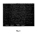
- Fig. 4 is an electron microscope photograph showing the surface condition of the reaction part.
- Fig. 2 (b) schematically illustrates the cross section of the reaction part of Fig. 4 .
- the induced current which flows when the reaction part of the sensor chip dissolves in a sample solution was measured to evaluate the solubility of the sensor chip. More specifically, the Faraday current was measured for the ten sensor chips to evaluate their solubility, and it was found that the average value was 160.1 (Table 1 and Fig. 5 ).
- the sensor output was measured, and it was found that the output sensitivity at a glucose concentration of 100 mg/dL and measuring time of 20 seconds was 154.7 (Table 2 and Fig. 6 ).
- the output variation was measured among the individual sensor chips and it was found that the CV value was 3% (Table 2 and Fig. 6 ).
- the CV value in this specification denotes a value obtained by the formula: (Standard deviation of sensor outputs/Average value of sensor outputs) ⁇ 100.
- Fig. 3 is an electron microscope photograph showing the surface condition of the reaction part.
- Fig. 2 (a) schematically illustrates the cross section of the reaction part shown in Fig. 3 .
- the sensor output sensitivity at a glucose concentration of 100 mg/dL and measuring time of 30 seconds was 99.2 (Table 2 and Fig. 6 ).
- Fig. 6 shows that the sensor output of the sensor chip of Example 1 is larger than that of Comparative Example 1, which shows that the sensor chip of Example 1 has a higher level of reliability than that of Comparative Example 1.
- the output variation of the sensor chips of Example 1 was also less than that of the sensor chips of Comparative Example 1.
- Table 1 Faraday current comparison Example 1 Comp.
- Example 1 1 156 12 2 155 19 3 159 25 4 168 18 5 152 15 6 155 20 7 166 16 8 170 18 9 162 17 10 158 16 Average value 160.10 17.60 CV value (%) 3.83 19.72 Standard deviation 6.14 3.47 MAX 170 25 MIN 152 12 MAX-MIN 9.90 7.40 Average-MIN 8.10 5.60
- Table 2 Sensor output comparison Example 1 Comp.
- Example 1 1 156 94 2 149 114 3 159 100 4 151 89 5 152 104 6 155 101 7 148 105 8 160 92 9 162 83 10 155 110 Average value 154.70 99.20 CV value (%) 3.05 9.75 Standard deviation 4.72 9.67 MAX 162 114 MIN 148 83 MAX-MIN 7.30 14.80 Average-MIN 6.70 16.20
- the electrode formation process (A2) was carried out as described below.
- a working electrode (21) and a counter electrode (22) which have a thickness of 0.06 ⁇ m and a size of 1 ⁇ 35 mm were formed by sputtering platinum at intervals of 1 mm on a polyimide film of 25 ⁇ m in thickness, and this was laminated with a white PET film (1) of 250 ⁇ m in thickness using adhesive.
- the electrodes were left uncovered to serve as a terminal (21a and 22a), and to the remaining portion thereof, a 100 ⁇ m-thick PET film (electrically insulating spacer sheet (5)) was laminated using adhesive, the PET film being provided with a rectangular window (reaction part cell (31)) large enough to extend over the two electrodes (1.5 ⁇ 5mm) (compartment to be used as a reaction part (4)) and a sample suction port (15) to serve as a suction path for leading a test sample to the rectangular window.
- reaction part cell (31) reaction part cell
- sample suction port 15
- reaction part (B2) The preparation process for the application liquid for forming reaction part (B2) was carried out as described below.
- the above experimental enzyme and experimental electron acceptor were added to the experimental cellulose suspension, thereby obtaining a mixed solution of three components.
- the obtained mixture is referred to as a mixed solution Ma.
- the mixed solution Ma was gently added dropwise to the experimental hydrophilic polymer solution Pa while stirring. After the dropwise addition was complete, stirring was continued for 5 minutes and then stopped. The condition of the mixture thoroughly changed to an aqueous suspension due to the precipitation of particulates.
- the aqueous suspension was used as an application liquid for forming a reaction part.
- reaction part (C2) a reaction part (4) was formed to obtain 100 pieces of desired biosensors.
- Example 2 The same procedure was conducted as in Example 2 except that a hydrophilic polymer was not used. More specifically, a reaction part-forming application liquid for comparison was prepared (an aqueous liquid with the same appearance as in Example 2). The prepared liquid was applied to a reaction part cell (31) on a plate with platinum electrodes to obtain a reaction part membrane, thereby producing 100 enzyme sensor chips for comparison.
- Example 2 Using 20 of the enzyme sensor chips (randomly selected) obtained in Example 2 and Comparative Example 2, the terminals (21a and 22a) thereof were connected to an enzyme sensor measurement device, and the current corresponding to the scanning potential was measured under the following conditions.
- a glucose solution with a concentration of 100 mg/dL was used as a sample.
- Ten enzyme sensor chips were preserved for 5 days and other ten chips were preserved for 40 days.
- Five ⁇ L of the test sample was injected into the suction port of each of the ten chips.
- an electric potential was applied with continuous variation in the manner of 0V ⁇ -0.2V ⁇ +0.2V at a scanning rate of 50 mv/s.
- the current was measured during this application of electric potential.
- the output sensitivity based on the current corresponding to each of the different potential values applied was measured.
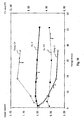
- Fig. 3 shows the average value of the output sensitivity of each of the ten chips.
- Output sensitivity is an integral value of the current value (integrated current value) between the applied electric potential of -0.2V ⁇ +0.2V. This value serves as an index to show the efficiency with which the reaction deviation of a test sample at the reaction part is promptly and surely input to an electrode. Accordingly, the larger the value is, the more the reaction deviation is input. In general, it is needless to say that the reactivity between the test sample component and the reaction part is important. It is extremely important from the viewpoint of measurement accuracy that all of the reaction deviation be input to the electrode if possible. Table 3 5 days 40 days Example 2 128 127 Comp. Example 2 92 81
- Fig. 10 shows that the output variation of the sensor chips of Example 2 is negligible as compared to that of Comparative Example 2. With respect to the sensor chips of Comparative Example 2, the measurement stopped at the 36 th day because the difference between Example 2 and Comparative Example 2 was remarkable.
- the CV value (%) was measured from the output variation of the outputs of the five sensor chips measured at each measurement day.
- the CV values are shown in the graph of Fig. 8 .
- Ex. CV denotes the CV value of Example 2 and Comp. CV denotes that of Comparative Example 2.
- the CV value was obtained by calculating the standard deviation from variations in outputs of the five sensor chips measured at each measurement day, dividing this by the average current value, and multiplying the result by 100.
- the solubility of the sensor chip reaction part with a sample is highly increased because the reaction part is formed using a suspension-like reaction part-forming application liquid produced by precipitation.
- the reaction part is formed using a suspension-like reaction part-forming application liquid produced by precipitation.
- the biosensor of the second invention even if the biosensor is stored for a long period, the reactivity with the sample component is scarcely changed, thereby achieving measurement with high precision. This simplifies the production control, inventory control, and handling of such biosensors by users. Further, reaction results with a sample can be more accurately and efficiently measured, thereby providing a biosensor with improved precision.
- the biosensor of the invention is characterized in the configuration of the sample suction port. More specifically, a projection formed at one side of an inner part of a holding space facilitates introduction of a liquid sample by its capillary action at one side of the holding space. This eliminates the need to form an outlet for discharging gas at the inner part of the holding space, which is required in prior-art biosensors. Thus, by this extremely simplified configuration, a liquid sample can be smoothly introduced into the holding space without leaving bubbles therein.
Landscapes
- Chemical & Material Sciences (AREA)
- Life Sciences & Earth Sciences (AREA)
- Organic Chemistry (AREA)
- Health & Medical Sciences (AREA)
- Wood Science & Technology (AREA)
- Zoology (AREA)
- Proteomics, Peptides & Aminoacids (AREA)
- Engineering & Computer Science (AREA)
- Molecular Biology (AREA)
- Immunology (AREA)
- Biochemistry (AREA)
- Physics & Mathematics (AREA)
- Analytical Chemistry (AREA)
- General Health & Medical Sciences (AREA)
- Microbiology (AREA)
- Biotechnology (AREA)
- Bioinformatics & Cheminformatics (AREA)
- Biophysics (AREA)
- General Engineering & Computer Science (AREA)
- Genetics & Genomics (AREA)
- Pathology (AREA)
- Electrochemistry (AREA)
- General Physics & Mathematics (AREA)
- Chemical Kinetics & Catalysis (AREA)
- Apparatus Associated With Microorganisms And Enzymes (AREA)
- Measuring Or Testing Involving Enzymes Or Micro-Organisms (AREA)
- Immobilizing And Processing Of Enzymes And Microorganisms (AREA)
Abstract
Applications Claiming Priority (5)
| Application Number | Priority Date | Filing Date | Title |
|---|---|---|---|
| JP2002235697 | 2002-08-13 | ||
| JP2002235697 | 2002-08-13 | ||
| JP2003003549 | 2003-01-09 | ||
| JP2003003549 | 2003-01-09 | ||
| PCT/JP2003/010117 WO2004017057A1 (ja) | 2002-08-13 | 2003-08-08 | バイオセンサとその製造方法 |
Publications (3)
| Publication Number | Publication Date |
|---|---|
| EP1548427A1 EP1548427A1 (en) | 2005-06-29 |
| EP1548427A4 EP1548427A4 (en) | 2007-12-26 |
| EP1548427B1 true EP1548427B1 (en) | 2011-01-19 |
Family
ID=31890525
Family Applications (1)
| Application Number | Title | Priority Date | Filing Date |
|---|---|---|---|
| EP03788056A Expired - Lifetime EP1548427B1 (en) | 2002-08-13 | 2003-08-08 | Biosensor and method for manufacturing same |
Country Status (9)
| Country | Link |
|---|---|
| US (1) | US7727367B2 (ja) |
| EP (1) | EP1548427B1 (ja) |
| JP (1) | JP4247440B2 (ja) |
| KR (1) | KR100684228B1 (ja) |
| CN (2) | CN101509889B (ja) |
| CA (1) | CA2494250C (ja) |
| DE (1) | DE60335812D1 (ja) |
| TW (1) | TWI235831B (ja) |
| WO (1) | WO2004017057A1 (ja) |
Families Citing this family (23)
| Publication number | Priority date | Publication date | Assignee | Title |
|---|---|---|---|---|
| US7918975B2 (en) * | 2005-11-17 | 2011-04-05 | Abbott Diabetes Care Inc. | Analytical sensors for biological fluid |
| JP2007212215A (ja) * | 2006-02-08 | 2007-08-23 | Matsushita Electric Ind Co Ltd | 多孔質担体、及び多孔質担体製造方法 |
| JP5406423B2 (ja) * | 2006-03-31 | 2014-02-05 | グンゼ株式会社 | 細粒化フェリシアン化カリウムの製造方法 |
| KR100776393B1 (ko) * | 2006-04-17 | 2007-11-28 | 주식회사 인포피아 | 바이오센서 및 그 제조방법 |
| CN101251506B (zh) * | 2008-03-15 | 2011-06-15 | 西北师范大学 | 一种导电聚苯胺/纤维素复合生物传感器的制备方法 |
| US8357276B2 (en) * | 2009-08-31 | 2013-01-22 | Abbott Diabetes Care Inc. | Small volume test strips with large sample fill ports, supported test strips, and methods of making and using same |
| US8354013B2 (en) | 2009-11-24 | 2013-01-15 | Abbott Diabetes Care Inc. | Analyte sensors comprising high-boiling point solvents |
| JP2013530409A (ja) * | 2010-07-14 | 2013-07-25 | 紅電醫學科技股▲分▼有限公司 | 体液サンプル検出用試験ストリップ |
| JP2012242366A (ja) * | 2011-05-24 | 2012-12-10 | Sharp Corp | バイオセンサとこれを用いた分析方法 |
| JP2014528583A (ja) * | 2011-10-03 | 2014-10-27 | シーピーフィルムズ インコーポレイティド | グルコースを測定するために貴金属を活性化させる方法と、関連するバイオセンサーの電極 |
| KR101239381B1 (ko) | 2012-05-02 | 2013-03-05 | 주식회사 아이센스 | 산화환원반응용 시약의 안정제 조성물 |
| JP6286835B2 (ja) * | 2013-02-26 | 2018-03-07 | 大日本印刷株式会社 | 濃度測定センサ用シートの製造方法 |
| CN103454321B (zh) * | 2013-03-28 | 2015-09-09 | 利多(香港)有限公司 | 生物传感器及其制造方法 |
| CN103412012B (zh) * | 2013-03-28 | 2015-09-09 | 利多(香港)有限公司 | 生物传感器 |
| US9523653B2 (en) * | 2013-05-09 | 2016-12-20 | Changsha Sinocare Inc. | Disposable test sensor with improved sampling entrance |
| CN104407025A (zh) * | 2014-11-19 | 2015-03-11 | 东莞市青麦田数码科技有限公司 | 一种电化学传感器及其制备方法 |
| ES2600527B1 (es) * | 2015-07-09 | 2018-01-17 | Biolan Microbiosensores, S.L. | Sistema para medir sulfito en muestras alimentarias mediante biosensor; método para la determinación de sulfito en muestras alimentarias utilizando el citado biosensor; y uso del citado biosensor para medir los valores de sulfito en muestras alimentarias |
| TWI589870B (zh) * | 2016-05-05 | 2017-07-01 | Vida Biotechnology Co Ltd | Biological test strip with isolated structure and method of use |
| CN105911116A (zh) * | 2016-05-16 | 2016-08-31 | 苏州感测通信息科技有限公司 | 一种有机磷农药快速检测纸芯片及其制作方法 |
| CN109946353A (zh) * | 2018-11-08 | 2019-06-28 | 利多(香港)有限公司 | 电势型生物传感器和检测方法 |
| CN111229345B (zh) * | 2020-01-22 | 2021-01-15 | 浙江大学 | 一种基于微纳光纤的微流控芯片流速传感器 |
| CN113106143A (zh) * | 2021-04-01 | 2021-07-13 | 广州南雪医疗器械有限公司 | 一种检测尿酸的试纸 |
| JP2024120513A (ja) * | 2023-02-24 | 2024-09-05 | 第一工業製薬株式会社 | 電気化学測定電極用コーティング剤、並びにそれを用いた電気化学測定電極、電気化学センサ、及び電気化学バイオセンサ |
Family Cites Families (14)
| Publication number | Priority date | Publication date | Assignee | Title |
|---|---|---|---|---|
| JP2517153B2 (ja) | 1989-09-21 | 1996-07-24 | 松下電器産業株式会社 | バイオセンサおよびその製造法 |
| DE69020908T2 (de) | 1989-12-15 | 1996-02-15 | Boehringer Mannheim Corp., Indianapolis, Ind. | Redox-vermittlungs-reagenz und biosensor. |
| FR2701117B1 (fr) * | 1993-02-04 | 1995-03-10 | Asulab Sa | Système de mesures électrochimiques à capteur multizones, et son application au dosage du glucose. |
| US5762770A (en) * | 1994-02-21 | 1998-06-09 | Boehringer Mannheim Corporation | Electrochemical biosensor test strip |
| US5651869A (en) * | 1995-02-28 | 1997-07-29 | Matsushita Electric Industrial Co., Ltd. | Biosensor |
| DE69810194T2 (de) | 1997-06-03 | 2003-11-20 | Matsushita Electric Industrial Co. Ltd., Osaka | Cholesterinsensor |
| US5994174A (en) * | 1997-09-29 | 1999-11-30 | The Regents Of The University Of California | Method of fabrication of display pixels driven by silicon thin film transistors |
| AU9595298A (en) | 1997-09-30 | 1999-04-23 | Mercury Diagnostics Inc. | Membrane based electrochemical test device and related methods |
| US6338790B1 (en) * | 1998-10-08 | 2002-01-15 | Therasense, Inc. | Small volume in vitro analyte sensor with diffusible or non-leachable redox mediator |
| ATE331949T1 (de) * | 1999-11-16 | 2006-07-15 | Matsushita Electric Industrial Co Ltd | Biosensor |
| JP2001281202A (ja) | 2000-01-27 | 2001-10-10 | Matsushita Electric Ind Co Ltd | バイオセンサおよびその製造方法 |
| JP4467711B2 (ja) | 2000-04-28 | 2010-05-26 | グンゼ株式会社 | 酵素センサおよびこれを用いた酵素センサ装置 |
| JP4576672B2 (ja) * | 2000-06-15 | 2010-11-10 | パナソニック株式会社 | バイオセンサ |
| US6447657B1 (en) * | 2000-12-04 | 2002-09-10 | Roche Diagnostics Corporation | Biosensor |
-
2003
- 2003-08-08 EP EP03788056A patent/EP1548427B1/en not_active Expired - Lifetime
- 2003-08-08 CN CN2009101284461A patent/CN101509889B/zh not_active Expired - Fee Related
- 2003-08-08 KR KR1020057002326A patent/KR100684228B1/ko not_active Expired - Fee Related
- 2003-08-08 US US10/524,380 patent/US7727367B2/en not_active Expired - Fee Related
- 2003-08-08 DE DE60335812T patent/DE60335812D1/de not_active Expired - Lifetime
- 2003-08-08 CN CNB038193396A patent/CN100533136C/zh not_active Expired - Fee Related
- 2003-08-08 CA CA002494250A patent/CA2494250C/en not_active Expired - Fee Related
- 2003-08-08 JP JP2005502026A patent/JP4247440B2/ja not_active Expired - Fee Related
- 2003-08-08 WO PCT/JP2003/010117 patent/WO2004017057A1/ja not_active Ceased
- 2003-08-12 TW TW092122096A patent/TWI235831B/zh not_active IP Right Cessation
Also Published As
| Publication number | Publication date |
|---|---|
| US7727367B2 (en) | 2010-06-01 |
| KR100684228B1 (ko) | 2007-02-22 |
| CN1675537A (zh) | 2005-09-28 |
| EP1548427A1 (en) | 2005-06-29 |
| CN101509889B (zh) | 2012-02-01 |
| CN100533136C (zh) | 2009-08-26 |
| TW200408810A (en) | 2004-06-01 |
| CA2494250C (en) | 2009-02-10 |
| CA2494250A1 (en) | 2004-02-26 |
| EP1548427A4 (en) | 2007-12-26 |
| JP4247440B2 (ja) | 2009-04-02 |
| DE60335812D1 (de) | 2011-03-03 |
| TWI235831B (en) | 2005-07-11 |
| WO2004017057A1 (ja) | 2004-02-26 |
| JPWO2004017057A1 (ja) | 2005-12-08 |
| KR20050071474A (ko) | 2005-07-07 |
| CN101509889A (zh) | 2009-08-19 |
| US20050265897A1 (en) | 2005-12-01 |
Similar Documents
| Publication | Publication Date | Title |
|---|---|---|
| EP1548427B1 (en) | Biosensor and method for manufacturing same | |
| US9546974B2 (en) | Concentration determination in a diffusion barrier layer | |
| US5658443A (en) | Biosensor and method for producing the same | |
| EP1124131B1 (en) | Biosensor and method of producing the same | |
| MX2011006046A (es) | Composiciones de reactivo con una concentracion baja de sal total y sistemas para biosensores. | |
| JPH04113262A (ja) | バイオセンサおよびその製造法 | |
| JP2005046001A (ja) | 脂質修飾酵素の製造方法およびバイオセンサ | |
| AU2016202064B2 (en) | Concentration determination in a diffusion barrier layer | |
| AU2014274588B2 (en) | Concentration determination in a diffusion barrier layer | |
| AU2012203435B2 (en) | Concentration determination in a diffusion barrier layer |
Legal Events
| Date | Code | Title | Description |
|---|---|---|---|
| PUAI | Public reference made under article 153(3) epc to a published international application that has entered the european phase |
Free format text: ORIGINAL CODE: 0009012 |
|
| 17P | Request for examination filed |
Effective date: 20050224 |
|
| AK | Designated contracting states |
Kind code of ref document: A1 Designated state(s): AT BE BG CH CY CZ DE DK EE ES FI FR GB GR HU IE IT LI LU MC NL PT RO SE SI SK TR |
|
| RAP1 | Party data changed (applicant data changed or rights of an application transferred) |
Owner name: GUNZE LIMITED |
|
| RBV | Designated contracting states (corrected) |
Designated state(s): DE FR GB IT |
|
| A4 | Supplementary search report drawn up and despatched |
Effective date: 20071123 |
|
| 17Q | First examination report despatched |
Effective date: 20100217 |
|
| GRAP | Despatch of communication of intention to grant a patent |
Free format text: ORIGINAL CODE: EPIDOSNIGR1 |
|
| GRAS | Grant fee paid |
Free format text: ORIGINAL CODE: EPIDOSNIGR3 |
|
| GRAA | (expected) grant |
Free format text: ORIGINAL CODE: 0009210 |
|
| AK | Designated contracting states |
Kind code of ref document: B1 Designated state(s): DE FR GB IT |
|
| REG | Reference to a national code |
Ref country code: GB Ref legal event code: FG4D |
|
| REF | Corresponds to: |
Ref document number: 60335812 Country of ref document: DE Date of ref document: 20110303 Kind code of ref document: P |
|
| REG | Reference to a national code |
Ref country code: DE Ref legal event code: R096 Ref document number: 60335812 Country of ref document: DE Effective date: 20110303 |
|
| RIN2 | Information on inventor provided after grant (corrected) |
Inventor name: DEGUCHI, TETSUJI,C/O RESEARCH & DEVELOPMENT CENTER Inventor name: MARUO, MASAHARU,C/O RESEARCH & DEVELOPMENT CENTER |
|
| PLBE | No opposition filed within time limit |
Free format text: ORIGINAL CODE: 0009261 |
|
| STAA | Information on the status of an ep patent application or granted ep patent |
Free format text: STATUS: NO OPPOSITION FILED WITHIN TIME LIMIT |
|
| PGFP | Annual fee paid to national office [announced via postgrant information from national office to epo] |
Ref country code: DE Payment date: 20110830 Year of fee payment: 9 Ref country code: FR Payment date: 20110812 Year of fee payment: 9 Ref country code: GB Payment date: 20110803 Year of fee payment: 9 |
|
| 26N | No opposition filed |
Effective date: 20111020 |
|
| PGFP | Annual fee paid to national office [announced via postgrant information from national office to epo] |
Ref country code: IT Payment date: 20110811 Year of fee payment: 9 |
|
| REG | Reference to a national code |
Ref country code: DE Ref legal event code: R097 Ref document number: 60335812 Country of ref document: DE Effective date: 20111020 |
|
| GBPC | Gb: european patent ceased through non-payment of renewal fee |
Effective date: 20120808 |
|
| REG | Reference to a national code |
Ref country code: FR Ref legal event code: ST Effective date: 20130430 |
|
| PG25 | Lapsed in a contracting state [announced via postgrant information from national office to epo] |
Ref country code: IT Free format text: LAPSE BECAUSE OF NON-PAYMENT OF DUE FEES Effective date: 20120808 |
|
| PG25 | Lapsed in a contracting state [announced via postgrant information from national office to epo] |
Ref country code: DE Free format text: LAPSE BECAUSE OF NON-PAYMENT OF DUE FEES Effective date: 20130301 Ref country code: GB Free format text: LAPSE BECAUSE OF NON-PAYMENT OF DUE FEES Effective date: 20120808 |
|
| PG25 | Lapsed in a contracting state [announced via postgrant information from national office to epo] |
Ref country code: FR Free format text: LAPSE BECAUSE OF NON-PAYMENT OF DUE FEES Effective date: 20120831 |
|
| REG | Reference to a national code |
Ref country code: DE Ref legal event code: R119 Ref document number: 60335812 Country of ref document: DE Effective date: 20130301 |