EP1548312A2 - Procédé et dispositif de fabrication d'un disque d'embrayage - Google Patents
Procédé et dispositif de fabrication d'un disque d'embrayage Download PDFInfo
- Publication number
- EP1548312A2 EP1548312A2 EP04254854A EP04254854A EP1548312A2 EP 1548312 A2 EP1548312 A2 EP 1548312A2 EP 04254854 A EP04254854 A EP 04254854A EP 04254854 A EP04254854 A EP 04254854A EP 1548312 A2 EP1548312 A2 EP 1548312A2
- Authority
- EP
- European Patent Office
- Prior art keywords
- core plate
- friction material
- annular core
- strip
- shaped friction
- Prior art date
- Legal status (The legal status is an assumption and is not a legal conclusion. Google has not performed a legal analysis and makes no representation as to the accuracy of the status listed.)
- Granted
Links
- 238000000034 method Methods 0.000 title claims abstract description 11
- 239000002783 friction material Substances 0.000 claims abstract description 173
- 238000005520 cutting process Methods 0.000 claims abstract description 52
- 238000003825 pressing Methods 0.000 claims abstract description 16
- 239000000853 adhesive Substances 0.000 claims abstract description 11
- 230000001070 adhesive effect Effects 0.000 claims abstract description 11
- 230000002093 peripheral effect Effects 0.000 claims abstract description 10
- JOYRKODLDBILNP-UHFFFAOYSA-N Ethyl urethane Chemical compound CCOC(N)=O JOYRKODLDBILNP-UHFFFAOYSA-N 0.000 claims description 12
- 239000000463 material Substances 0.000 abstract 2
- 238000004519 manufacturing process Methods 0.000 description 15
- 238000004080 punching Methods 0.000 description 4
- 238000010586 diagram Methods 0.000 description 3
- 239000000428 dust Substances 0.000 description 2
- 239000002184 metal Substances 0.000 description 2
- 239000000654 additive Substances 0.000 description 1
- 230000000996 additive effect Effects 0.000 description 1
- 230000001174 ascending effect Effects 0.000 description 1
- 239000011230 binding agent Substances 0.000 description 1
- 230000005540 biological transmission Effects 0.000 description 1
- 230000006835 compression Effects 0.000 description 1
- 238000007906 compression Methods 0.000 description 1
- 239000000835 fiber Substances 0.000 description 1
- 230000013011 mating Effects 0.000 description 1
- 238000010408 sweeping Methods 0.000 description 1
Images


Classifications
-
- F—MECHANICAL ENGINEERING; LIGHTING; HEATING; WEAPONS; BLASTING
- F16—ENGINEERING ELEMENTS AND UNITS; GENERAL MEASURES FOR PRODUCING AND MAINTAINING EFFECTIVE FUNCTIONING OF MACHINES OR INSTALLATIONS; THERMAL INSULATION IN GENERAL
- F16D—COUPLINGS FOR TRANSMITTING ROTATION; CLUTCHES; BRAKES
- F16D13/00—Friction clutches
- F16D13/58—Details
- F16D13/60—Clutching elements
- F16D13/64—Clutch-plates; Clutch-lamellae
- F16D13/648—Clutch-plates; Clutch-lamellae for clutches with multiple lamellae
-
- F—MECHANICAL ENGINEERING; LIGHTING; HEATING; WEAPONS; BLASTING
- F16—ENGINEERING ELEMENTS AND UNITS; GENERAL MEASURES FOR PRODUCING AND MAINTAINING EFFECTIVE FUNCTIONING OF MACHINES OR INSTALLATIONS; THERMAL INSULATION IN GENERAL
- F16D—COUPLINGS FOR TRANSMITTING ROTATION; CLUTCHES; BRAKES
- F16D69/00—Friction linings; Attachment thereof; Selection of coacting friction substances or surfaces
- F16D2069/004—Profiled friction surfaces, e.g. grooves, dimples
-
- F—MECHANICAL ENGINEERING; LIGHTING; HEATING; WEAPONS; BLASTING
- F16—ENGINEERING ELEMENTS AND UNITS; GENERAL MEASURES FOR PRODUCING AND MAINTAINING EFFECTIVE FUNCTIONING OF MACHINES OR INSTALLATIONS; THERMAL INSULATION IN GENERAL
- F16D—COUPLINGS FOR TRANSMITTING ROTATION; CLUTCHES; BRAKES
- F16D69/00—Friction linings; Attachment thereof; Selection of coacting friction substances or surfaces
- F16D69/04—Attachment of linings
- F16D2069/0425—Attachment methods or devices
- F16D2069/0491—Tools, machines, processes
-
- F—MECHANICAL ENGINEERING; LIGHTING; HEATING; WEAPONS; BLASTING
- F16—ENGINEERING ELEMENTS AND UNITS; GENERAL MEASURES FOR PRODUCING AND MAINTAINING EFFECTIVE FUNCTIONING OF MACHINES OR INSTALLATIONS; THERMAL INSULATION IN GENERAL
- F16D—COUPLINGS FOR TRANSMITTING ROTATION; CLUTCHES; BRAKES
- F16D2250/00—Manufacturing; Assembly
-
- Y—GENERAL TAGGING OF NEW TECHNOLOGICAL DEVELOPMENTS; GENERAL TAGGING OF CROSS-SECTIONAL TECHNOLOGIES SPANNING OVER SEVERAL SECTIONS OF THE IPC; TECHNICAL SUBJECTS COVERED BY FORMER USPC CROSS-REFERENCE ART COLLECTIONS [XRACs] AND DIGESTS
- Y10—TECHNICAL SUBJECTS COVERED BY FORMER USPC
- Y10T—TECHNICAL SUBJECTS COVERED BY FORMER US CLASSIFICATION
- Y10T156/00—Adhesive bonding and miscellaneous chemical manufacture
- Y10T156/12—Surface bonding means and/or assembly means with cutting, punching, piercing, severing or tearing
- Y10T156/1313—Cutting element simultaneously bonds [e.g., cut seaming]
-
- Y—GENERAL TAGGING OF NEW TECHNOLOGICAL DEVELOPMENTS; GENERAL TAGGING OF CROSS-SECTIONAL TECHNOLOGIES SPANNING OVER SEVERAL SECTIONS OF THE IPC; TECHNICAL SUBJECTS COVERED BY FORMER USPC CROSS-REFERENCE ART COLLECTIONS [XRACs] AND DIGESTS
- Y10—TECHNICAL SUBJECTS COVERED BY FORMER USPC
- Y10T—TECHNICAL SUBJECTS COVERED BY FORMER US CLASSIFICATION
- Y10T29/00—Metal working
- Y10T29/51—Plural diverse manufacturing apparatus including means for metal shaping or assembling
-
- Y—GENERAL TAGGING OF NEW TECHNOLOGICAL DEVELOPMENTS; GENERAL TAGGING OF CROSS-SECTIONAL TECHNOLOGIES SPANNING OVER SEVERAL SECTIONS OF THE IPC; TECHNICAL SUBJECTS COVERED BY FORMER USPC CROSS-REFERENCE ART COLLECTIONS [XRACs] AND DIGESTS
- Y10—TECHNICAL SUBJECTS COVERED BY FORMER USPC
- Y10T—TECHNICAL SUBJECTS COVERED BY FORMER US CLASSIFICATION
- Y10T29/00—Metal working
- Y10T29/53—Means to assemble or disassemble
- Y10T29/53909—Means comprising hand manipulatable tool
-
- Y—GENERAL TAGGING OF NEW TECHNOLOGICAL DEVELOPMENTS; GENERAL TAGGING OF CROSS-SECTIONAL TECHNOLOGIES SPANNING OVER SEVERAL SECTIONS OF THE IPC; TECHNICAL SUBJECTS COVERED BY FORMER USPC CROSS-REFERENCE ART COLLECTIONS [XRACs] AND DIGESTS
- Y10—TECHNICAL SUBJECTS COVERED BY FORMER USPC
- Y10T—TECHNICAL SUBJECTS COVERED BY FORMER US CLASSIFICATION
- Y10T428/00—Stock material or miscellaneous articles
- Y10T428/24—Structurally defined web or sheet [e.g., overall dimension, etc.]
- Y10T428/24479—Structurally defined web or sheet [e.g., overall dimension, etc.] including variation in thickness
- Y10T428/2457—Parallel ribs and/or grooves
Definitions
- the present invention relates to an improvement of a process and a device for producing a clutch friction plate by bonding a plurality of friction material segments to an annular flat face of an annular core plate so that oil channels are formed between the friction material segments.
- the friction material segments are obtained by cutting them in turn from the leading edge of the band-shaped friction material, which is fed in a direction along a tangent to the annular core plate, and are then bonded to the annular core plate, resulting in a low degree of freedom in the shape of the oil channels formed between the friction material segments.
- the ratio of the area occupied by the friction material segments so obtained relative to the area of the band-shaped friction material required, that is, the yield, is low.
- the present invention has been accomplished under the above-mentioned circumstances, and it is an object thereof to provide a process for producing a clutch friction plate, the process ensuring a high degree of freedom in the shape of the oil channels and an improved yield in the production of the friction material segments, as well as a device for producing the clutch friction plate, the device being capable of appropriately carrying out the production process.
- a process for producing a clutch friction plate by bonding a plurality of friction material segments to an annular flat face of an annular core plate so that oil channels are formed between the friction material segments comprising: a step of forming a plurality of strip-shaped friction materials by cutting a band-shaped friction material along its longitudinal direction while feeding the band-shaped friction material in a direction along one diameter of the annular core plate; a step of aligning and holding portions, corresponding to the friction material segments, of leading edge parts of the plurality of strip-shaped friction materials in positions above the annular core plate while positioning the portions in the peripheral direction and in the direction along said one diameter of the annular core plate; a step of forming the plurality of friction material segments by cutting off the leading edge parts of the plurality of strip-shaped friction materials positioned above the annular core plate along a cutting-off line that includes at least an arc line that follows the outer periphery of the annular core plate;
- the plurality of strip-shaped friction materials are formed by cutting the band-shaped friction material in its longitudinal direction, and the portions of the leading edge parts of these strip-shaped friction materials that correspond to the friction material segments are cut off at the cutting - off line that includes at least the arc line that follows the outer periphery of the annular core plate while the portions are positioned and held in the positions above the annular core plate so as to form the plurality of friction material segments, which are pressed against and bonded to the annular flat face of the annular core plate coated with an adhesive. Therefore, it is possible to increase the degree of freedom in the width and shape of the oil channels between the friction material segments, and moreover the production yield of the friction material segments can be improved.
- a device for producing a clutch friction plate by bonding a plurality of friction material segments to an annular flat face of an annular core plate so that oil channels are formed between the friction material segments comprising: support means that is capable of positioning and supporting the annular core plate so that the annular flat face coated with an adhesive faces upward and the annular core plate can be pivoted intermittently around an axis thereof; a rotating receiving blade that rotates at a fixed position so as to be in contact with a lower face of a band-shaped friction material extending in a direction along one diameter of the annular core plate positioned and supported by the support means; one rotating round blade or a plurality of coaxial rotating round blades that rotate so as to be in contact with the outer periphery of the rotating receiving blade and cut the band-shaped friction material along its longitudinal direction to form a plurality of strip-shaped friction materials; a feed roller that is in contact from beneath with the plurality of strip-shaped friction materials in common so as
- the plurality of strip-shaped friction materials are formed by cutting the band-shaped friction material by means of both the rotating receiving blade which is in contact with the lower face of the band-shaped friction material, and one rotating round blade or the plurality of coaxial rotating round blades which rotate while being in contact with the outer periphery of the rotating receiving blade; the plurality of strip-shaped friction materials thus formed are fed toward the annular core plate by means of both the feed roller which is in contact from beneath with the strip-shaped friction materials in common, and the plurality of urethane rollers which are individually in contact with the upper faces of the strip-shaped friction materials; the leading edge parts of the plurality of strip-shaped friction materials positioned and held by the positioning block in the positions above the annular core plate are cut off by means of both the cutting blade which moves vertically and has at least the arc part that follows the outer periphery of the annular core plate, and the receiving blade mounted on the positioning block, so as to form the plurality of friction material segments; and these friction material segments are pressed against the
- a clutch friction plate 15A is formed by bonding, for example, eight segment groups 19A to each of annular flat faces 16a on opposite sides of a metal annular core plate 16.
- the segment group 19A includes a triangular friction material segment 17 and four rectangular friction material segments 18 which are arranged in an anticlockwise direction from the friction material segment 17, each of the friction material segments 17 and 18 being made of a fiber component, an additive component, a binder component, etc.
- Oil channels 20 are formed between adjacent friction material segments 17 and 18, and 18 and 18.
- one segment group 19A is simultaneously bonded to the annular flat face 16a of the annular core plate 16 by carrying out Steps (a) to (d), which will be described below.
- Steps (a) to (d) By repeating Steps (a) to (d) eight times, the friction material segments 17 and 18 are bonded to the annular flat face 16a on one side of the annular core plate 16.
- this production device includes: support means 28 that can intermittently pivot while positioning and supporting the annular core plate 16 in a manner in which the annular flat face 16a coated with an adhesive faces upward; cutting means 29 that cuts the band-shaped friction material 21 which extends in a direction along one diameter of the annular core plate 16 positioned and supported by the support means 28, at for example four positions to form five strip-shaped friction materials 22 and 23; feeding means 30 for feeding the strip-shaped friction materials 22 and 23 toward the annular core plate 16; a positioning block 31 that holds the portions, corresponding to the friction material segments 17 and 18, of the leading edge parts of the five strip-shaped friction materials 22 and 23 so as to position the portions in the positions above the annular core plate 16; cutting-off means 32 that cuts off the leading edge parts of the five strip-shaped friction materials 22 and 23 positioned and held by the positioning block 31 to form the five friction material segments 17 and 18; and pressing means 33 that presses the cut-off five friction material
- the support means 28 includes a disc-shaped support table 36 pivotably supported, via a bearing 35, on a base 34 fixed to the floor, an electric motor 37 supported by the base 34 beneath the support table 36 so that the electric motor 37 exhibits a driving force to pivot the support table 36, and a transmission mechanism 38 provided between the support table 36 and the electric motor 37 so as to transmit the driving force of the electric motor 37 to the support table 36 while reducing its speed.
- the annular core plate 16 is positioned and supported on the support table 36 with the axis of the annular core plate 16 aligning with the pivot axis of the support table 36 so that the annular flat face 16a coated with an adhesive (not illustrated) faces upward. Operation of the electric motor 37 is controlled so that the annular core plate 16 is made to intermittently pivot around its axis. Since eight segment groups 19A are bonded to the annular flat face 16a of the annular core plate 16 in the first embodiment, the electric motor 37 is controlled so that the annular core plate 16, that is, the support table 36, is pivoted intermittently by 45 degrees each time.
- the cutting means 29 includes a rotating receiving blade 40 that rotates at a fixed position so as to be in contact with the lower face of the band-shaped friction material 21, and one rotating round blade 41 or a plurality of coaxial rotating round blades 41 that rotate so as to be in contact with the outer periphery of the rotating receiving blade 40 and cut the band-shaped friction material 21 along its longitudinal direction, thus forming a plurality of strip-shaped friction materials 22 and 23. Since the five strip-shaped friction materials 22 and 23 are formed from the band-shaped friction material 21 in the first embodiment, four coaxially rotating round blades 41 rotate so as to be in contact with the outer periphery of the rotating receiving blade 40.
- a rotating shaft 42 of the rotating receiving blade 40 and a common rotating shaft 43 of the rotating round blades 41 are connected to a rotating drive source 44 so that the rotating shaft 42 and the rotating shaft 43 rotate in opposite directions in synchronism with each other.
- the feeding means 30 includes a feed roller 45 that is in contact from beneath with the strip-shaped friction materials 22 and 23 in common, and a plurality (five in the first embodiment) of urethane rollers 46 that rotate individually in contact with upper faces of the strip-shaped friction materials 22 and 23 while sandwiching the strip-shaped friction materials 22 and 23 between the urethane rollers 46 and the feed roller 45.
- a rotating shaft 47 of the feed roller 45 is rotatably supported by a pair of support plates 49 arranged on opposite sides of the strip-shaped friction materials 22 and 23, and one end of the rotating shaft 47 is connected to a drive source 50 mounted in one of the support plates 49.
- a common rotating shaft 48 of the urethane rollers 46 is rotatably supported by the support plates 49 so that the urethane rollers 46 rotate by following the strip-shaped friction materials 22 and 23 fed by the feed roller 45.
- the positioning block 31 is disposed between the support table 36 and the feeding means 30 so as to overlap a part of the annular core plate 16 on the support table 36, and is spring-biased upward while being capable of ascending and descending in a limited range. That is, a pair of guide tubes 51 are provided so as to stand on the base 34 on opposite sides of the strip-shaped friction materials 22 and 23, upper ends of mating shafts 52 fitted from above into the guide tubes 51 are secured to the positioning block 31, and a pair of coil springs 53 surrounding the guide tubes 51 are provided under compression between the base 34 and the positioning block 31.
- the pair of support plates 49 supporting the feeding means 30 are secured to the positioning block 31, so that the feeding means 30 also ascends and descends together with the positioning block 31.
- the positioning block 31 integrally includes a block main portion 31a having guide grooves 54 and 55 on a lower face, through which the strip-shaped friction materials 22 and 23 are inserted, and a protruding portion 31b protruding from a lower part of the block main portion 31 a toward the annular support plate 16 on the support table 36.
- the protruding portion 31b is formed into a comb shape so as to position the portions, corresponding to the friction material segments 17 and 18, of the leading edge parts of the strip-shaped friction materials 22 and 23 while positioning in the peripheral direction of the annular core plate 16 and in a direction along one diameter of the annular core plate 16.
- portions protruding toward the annular core plate 16 from the guide grooves 54 and 55 of the block main portion 31a situate at positions fixed by the protruding portion 31b in the peripheral direction of the annular core plate 16 and in the direction along said one diameter of the annular core plate 16.
- a sliding-contact projection 31c which is in resilient sliding contact with a cam 56 disposed above the block main portion 31a, is projectingly provided at the upper end of the block main portion 31 a of the positioning block 31, and a rotating shaft 57 of the cam 56 is connected to a rotating drive source 58.
- the cam 56 is thus rotated by the rotating drive source 58, and the block main portion 31a, that is, the positioning block 31, ascends and descends accompanying the rotation of the cam 56.
- the rotating drive source 58 is mounted in a support frame 59 fixed to the base 34 on opposite sides of the positioning block 31.
- the cutting-off means 32 includes a cutting blade 60 and a receiving blade 61.
- the cutting blade 60 can move vertically relative to the annular core plate 16 positioned and supported on the support table 36 of the support means 28, and has at least an arc part 60a that follows the outer periphery of the annular core plate 16.
- the receiving blade 61 is fixed to the positioning block 31 so that the receiving blade 61, in cooperation with the cutting blade 60, cuts off the leading edge parts of the strip-shaped friction materials 22 and 23 positioned and held by the positioning block 31 to form the five friction material segments 17 and 18.
- the cutting blade 60 is supported on the positioning block 31 so that it is vertically movable relative to the positioning block 31.
- a space for allowing the cutting blade 60 to move vertically is formed between the block main portion 31a and the protruding portion 31b of the positioning block 31.
- the cutting blade 60 having at least the arc part 60a that follows the outer periphery of the annular core plate 16 includes not only the arc part 60a but also a straight line part 60b that intersects the arc part 60a because, among the five friction material segments 17 and 18 forming the segment group 19A, the friction material segment 17 at one end in the peripheral direction of the annular core plate 16, that is, in the direction in which the friction material segments 17 and 18 are arranged, is triangular.
- the receiving blade 61 is formed as shown in FIG. 8 so as to correspond to the shape of the cutting blade 60, and is fixed to a lower face of the block main portion 31a so as to block from below the guide grooves 54 and 55 on the lower face of the block main portion 31a of the positioning block 31.
- a lower end of a connecting rod 63 extending upward is pivotably connected to the cutting-off means 32 having the cutting blade 60, and an upper end of the connecting rod 63 is pivotably connected to the rotating shaft 57 of the cam 56 at a position that is eccentric with respect to the rotational axis of the rotating shaft 57.
- the cutting blade 60 therefore moves vertically accompanying rotation of the cam 56, so that the positioning block 31, the receiving blade 61, and the cutting blade 60 can be raised and lowered by the common rotating drive source 58 while the cutting blade 60 can move vertically relative to the positioning block 31 and the receiving blade 61.
- the pressing means 33 is formed from a plurality of pressing projections 64 and 65 integrally provided with the cutting blade 60 so as to correspond to the friction material segments 17 and 18 respectively, which are to be bonded to the annular core plate 16.
- the pressing projections 64 and 65 are formed into a shape such that they are inserted from above into the protruding portion 31b of the positioning block 31 when the cutting blade 60 moves downward relative to the positioning block 31.
- the triangular friction material segment 17 is cut off from the leading edge part of the strip-shaped friction material 22 by means of the cutting blade 60 and the receiving blade 61, the triangular scrap 25 is generated.
- An opening 67 is provided in a portion of the protruding portion 31b corresponding to this scrap, and the cutting blade 60 is provided with a sweeping-out member 66 for sweeping the scrap 25 remaining on an upper face of the receiving blade 61 outward via the opening 67.
- the strip-shaped friction materials 22 and 23 fed by the feeding means 30 are positioned and held by the positioning block 31, which is present at a relatively high position as shown in FIG. 5 and FIG. 7, and are then moved directly above the annular core plate 16 on the support table 36 as the positioning block 31 descends. Subsequently, the cutting blade 60 moves downward relative to the positioning block 31, thereby cutting off the friction material segments 17 and 18 from the leading edge parts of the strip-shaped friction materials 22 and 23 by means of the cutting blade 60 and the receiving blade 61. When the cutting blade 60 then further descends as shown in FIG. 9 and FIG.
- the friction material segments 17 and 18 are pressed downward by the pressing projections 64 and 65 of the pressing means 33 while being guided by the positioning block 31 and the receiving blade 61, and pressed against the annular flat face 16a of the annular core plate 16, which has been coated with an adhesive.
- the band-shaped friction material 21 is cut by means of both the rotating receiving blade 40 which is in contact with the lower face of the band-shaped friction material 21, and one rotating round blade 41 or a plurality (four in the first embodiment) of coaxial rotating round blades 41 which rotate so as to be in contact with the outer periphery of the rotating receiving blade 40, thus forming the plurality of strip-shaped friction materials 22 and 23;
- the plurality of strip-shaped friction materials 22 and 23 thus formed are fed toward the annular core plate 16 by means of both the feed roller 45 which is in contact from beneath with the strip -shaped friction materials 22 and 23 in common, and the plurality (five in the first embodiment) of urethane rollers 46 which rotate in individual contact with the upper faces of the strip-shaped friction materials 22 and 23;
- the leading edge parts of the plurality of strip-shaped friction materials 22 and 23 positioned and held in the positions above the annular core plate 16 by the positioning block 31 are cut off by means of both the cutting blade 60 which moves vertically
- the rotating receiving blade 40 and the rotating round blades 41 are used when the strip-shaped friction materials 22 and 23 are formed by cutting the band-shaped friction material 21, and the cutting blade 60 and the receiving blade 61 are used when the friction material segments 17 and 18 are cut off from the leading edge parts of the strip-shaped friction materials 22 and 23. Therefore, it is possible to minimize generation of shaggy cut portions and dust accompanying the cutting, and to appropriately carry out the above-mentioned production process with a simple and inexpensive arrangement as compared with an arrangement employing a punching-out die.
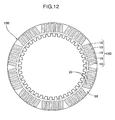
- FIG. 12 shows a second embodiment of the present invention.
- a clutch friction plate 15B is formed by bonding, to annular flat faces 16a on opposite sides of a metal annular core plate 16, for example, ten segment groups 19B each containing a plurality of, for example five, friction material segments 18 having an identical shape and being parallel to each other so that oil channels 20 are formed between adjacent friction material segments 18 of each group 19B and triangular oil channels 68 are formed between the groups 19B.
- the cutting-off line used when cutting off the friction material segments 18 from five strip-shaped friction materials may contain only an arc line, the arrangement of cutting-off means 32 in the production device can be further simplified, and moreover no scrap is generated, thus increasing the yield to 100%.
Landscapes
- Engineering & Computer Science (AREA)
- General Engineering & Computer Science (AREA)
- Mechanical Engineering (AREA)
- Braking Arrangements (AREA)
- Mechanical Operated Clutches (AREA)
Applications Claiming Priority (2)
| Application Number | Priority Date | Filing Date | Title |
|---|---|---|---|
| JP2003425562A JP3971745B2 (ja) | 2003-12-22 | 2003-12-22 | クラッチ用摩擦板の製造方法および装置 |
| JP2003425562 | 2003-12-22 |
Publications (3)
| Publication Number | Publication Date |
|---|---|
| EP1548312A2 true EP1548312A2 (fr) | 2005-06-29 |
| EP1548312A3 EP1548312A3 (fr) | 2006-04-26 |
| EP1548312B1 EP1548312B1 (fr) | 2009-06-03 |
Family
ID=34544947
Family Applications (1)
| Application Number | Title | Priority Date | Filing Date |
|---|---|---|---|
| EP04254854A Expired - Lifetime EP1548312B1 (fr) | 2003-12-22 | 2004-08-12 | Procédé et dispositif de fabrication d'un disque d'embrayage |
Country Status (5)
| Country | Link |
|---|---|
| US (2) | US7240413B2 (fr) |
| EP (1) | EP1548312B1 (fr) |
| JP (1) | JP3971745B2 (fr) |
| CA (1) | CA2478134C (fr) |
| DE (1) | DE602004021341D1 (fr) |
Cited By (4)
| Publication number | Priority date | Publication date | Assignee | Title |
|---|---|---|---|---|
| EP1574733B1 (fr) * | 2004-03-12 | 2008-01-16 | Kabushiki Kaisha F.C.C. | Procédé pour fabriquer un disque à friction d'un embrayage humide |
| EP1876369A3 (fr) * | 2006-07-05 | 2011-01-19 | ZF Friedrichshafen AG | Disques de frottement pour un couplage en milieu humide pour un véhicule |
| CN109804172A (zh) * | 2016-11-16 | 2019-05-24 | 舍弗勒技术股份两合公司 | 湿式多片离合器 |
| CN111173854A (zh) * | 2020-01-06 | 2020-05-19 | 陈威 | 机械压力机离合器摩擦块检测装置 |
Families Citing this family (6)
| Publication number | Priority date | Publication date | Assignee | Title |
|---|---|---|---|---|
| JP2011127687A (ja) * | 2009-12-17 | 2011-06-30 | F C C:Kk | 湿式多板摩擦クラッチ装置 |
| US9943938B2 (en) | 2011-12-09 | 2018-04-17 | Borgwarner Inc. | Method and apparatus for making a friction plate |
| JP5500663B2 (ja) * | 2012-12-07 | 2014-05-21 | 株式会社エフ・シー・シー | 湿式多板摩擦クラッチ装置 |
| CN109399114B (zh) * | 2018-12-11 | 2023-12-29 | 宁波隆威婴儿用品有限公司 | 一种梳体植粒机 |
| JP2020101210A (ja) * | 2018-12-20 | 2020-07-02 | いすゞ自動車株式会社 | シート貼付装置及びシート貼付方法 |
| USD951064S1 (en) * | 2019-09-20 | 2022-05-10 | Caterpillar Inc. | Spacer |
Citations (1)
| Publication number | Priority date | Publication date | Assignee | Title |
|---|---|---|---|---|
| JPH0468491A (ja) | 1990-07-10 | 1992-03-04 | Sanyo Electric Co Ltd | 自動販売機 |
Family Cites Families (20)
| Publication number | Priority date | Publication date | Assignee | Title |
|---|---|---|---|---|
| US3048250A (en) * | 1959-10-26 | 1962-08-07 | Lambert & Brake Corp | Friction disc for brakes, clutches and the like |
| US3897860A (en) * | 1973-11-19 | 1975-08-05 | Borg Warner | Wet clutch with coolant distributor |
| SE7414359L (sv) * | 1974-11-15 | 1976-05-17 | Bofors Ab | Sett att kyla en vat lamellkoppling jemte herfor avsedd kopplingslamell |
| US4260047A (en) * | 1979-12-03 | 1981-04-07 | General Motors Corporation | Friction disc and method of making same |
| JPS6377944A (ja) | 1986-09-19 | 1988-04-08 | F C C:Kk | クラツチ用摩擦板の製造方法および製造装置 |
| US4878282A (en) * | 1987-09-04 | 1989-11-07 | Borg-Warner Automotive Gmbh | Method for the production of friction plates, synchronizing blocker rings or similar structures |
| JPS6474331A (en) | 1987-09-16 | 1989-03-20 | Akebono Res & Dev Centre | Wet type friction material |
| US5094331A (en) * | 1988-03-18 | 1992-03-10 | Honda Giken Kogyo Kabushiki Kaisha | Wet-type multiplate clutch |
| JPH0468494A (ja) | 1990-07-09 | 1992-03-04 | Nec Corp | 販売時点情報管理システム |
| US5571372A (en) * | 1992-07-21 | 1996-11-05 | Kabushiki Kaisha F.C.C. | Process and apparatus for manufacturing clutch friction plate |
| US5460255A (en) * | 1993-03-25 | 1995-10-24 | Borg-Warner Automotive, Inc. | Universal segmented friction clutch facing |
| JP3623527B2 (ja) * | 1993-12-24 | 2005-02-23 | Nskワーナー株式会社 | ロックアップ機構付きトルクコンバータ |
| JPH0841621A (ja) * | 1994-05-25 | 1996-02-13 | Aisin Seiki Co Ltd | 摩擦プレートの製造方法及びリング状摩擦プレートの製造方法 |
| US5776288A (en) * | 1996-05-07 | 1998-07-07 | Automotive Composites Company | Method and apparatus for lined clutch plate |
| US5858511A (en) * | 1997-03-11 | 1999-01-12 | Eaton Corporation | Grooved friction material, method of making same, and wet friction member using grooved friction material |
| US5897737A (en) | 1997-05-07 | 1999-04-27 | Borg-Warner Automotive, Inc. | Method for making a core plate having multiple friction material segments |
| JP3643018B2 (ja) | 1999-07-22 | 2005-04-27 | アイシン化工株式会社 | クラッチ用摩擦板の製造方法及び製造装置 |
| JP4068491B2 (ja) | 2003-04-01 | 2008-03-26 | 日本板硝子株式会社 | 光線検出装置 |
| JP4068494B2 (ja) | 2003-04-08 | 2008-03-26 | アルパイン株式会社 | 通信データ中継方法および車々間通信システム |
| EP1574733B1 (fr) | 2004-03-12 | 2008-01-16 | Kabushiki Kaisha F.C.C. | Procédé pour fabriquer un disque à friction d'un embrayage humide |
-
2003
- 2003-12-22 JP JP2003425562A patent/JP3971745B2/ja not_active Expired - Fee Related
-
2004
- 2004-08-09 US US10/913,497 patent/US7240413B2/en not_active Expired - Lifetime
- 2004-08-12 EP EP04254854A patent/EP1548312B1/fr not_active Expired - Lifetime
- 2004-08-12 DE DE602004021341T patent/DE602004021341D1/de not_active Expired - Lifetime
- 2004-08-17 CA CA002478134A patent/CA2478134C/fr not_active Expired - Fee Related
-
2007
- 2007-06-13 US US11/808,820 patent/US7434300B2/en not_active Expired - Lifetime
Patent Citations (1)
| Publication number | Priority date | Publication date | Assignee | Title |
|---|---|---|---|---|
| JPH0468491A (ja) | 1990-07-10 | 1992-03-04 | Sanyo Electric Co Ltd | 自動販売機 |
Cited By (7)
| Publication number | Priority date | Publication date | Assignee | Title |
|---|---|---|---|---|
| EP1574733B1 (fr) * | 2004-03-12 | 2008-01-16 | Kabushiki Kaisha F.C.C. | Procédé pour fabriquer un disque à friction d'un embrayage humide |
| EP1876369A3 (fr) * | 2006-07-05 | 2011-01-19 | ZF Friedrichshafen AG | Disques de frottement pour un couplage en milieu humide pour un véhicule |
| US8113330B2 (en) | 2006-07-05 | 2012-02-14 | Zf Friedrichshafen Ag | Friction disk for a wet-running clutch for a motor vehicle |
| US8205734B2 (en) | 2006-07-05 | 2012-06-26 | Zf Friedrichshafen Ag | Friction disk for a wet-running clutch for a motor vehicle |
| CN109804172A (zh) * | 2016-11-16 | 2019-05-24 | 舍弗勒技术股份两合公司 | 湿式多片离合器 |
| CN111173854A (zh) * | 2020-01-06 | 2020-05-19 | 陈威 | 机械压力机离合器摩擦块检测装置 |
| CN111173854B (zh) * | 2020-01-06 | 2020-10-09 | 陈威 | 机械压力机离合器摩擦块检测装置 |
Also Published As
| Publication number | Publication date |
|---|---|
| DE602004021341D1 (de) | 2009-07-16 |
| JP2005180651A (ja) | 2005-07-07 |
| EP1548312A3 (fr) | 2006-04-26 |
| US20050133332A1 (en) | 2005-06-23 |
| US7240413B2 (en) | 2007-07-10 |
| US7434300B2 (en) | 2008-10-14 |
| JP3971745B2 (ja) | 2007-09-05 |
| EP1548312B1 (fr) | 2009-06-03 |
| CA2478134A1 (fr) | 2005-06-22 |
| US20080034564A1 (en) | 2008-02-14 |
| CA2478134C (fr) | 2007-12-18 |
Similar Documents
| Publication | Publication Date | Title |
|---|---|---|
| US7434300B2 (en) | Process and device for producing clutch friction plate | |
| CN116545190A (zh) | 扁线定子绕组生产系统及生产工艺 | |
| US12483077B2 (en) | Split-type laminated iron core and method for manufacturing split-type laminated iron core | |
| CN1187006C (zh) | 转辊式脱毛器 | |
| JPH06246529A (ja) | 連続波状体の切断装置 | |
| US20060022301A1 (en) | Corrugation forming apparatus, corrugation forming method, and fuel cell metal separator formed by the corrugation forming method | |
| CN206368173U (zh) | 裁剪机机头及裁剪机 | |
| CN115213263B (zh) | 一种可微调的打印机内弹片冲压机 | |
| TWI885010B (zh) | 板材切斷裝置 | |
| CN114951814B (zh) | 一种送料一体式液压剪板机 | |
| KR970000277Y1 (ko) | 필름포장체의 결속장치 | |
| JP6785484B1 (ja) | ヘリカルギアプレートの製造装置 | |
| US7392586B2 (en) | Sheet feed shaft | |
| JP2013166172A (ja) | 抜き加工装置 | |
| CN221850304U (zh) | 一种塑料切粒装置 | |
| JP2003311347A (ja) | ロータリーカム式プレス装置 | |
| CN101086286A (zh) | 离合器用摩擦片的制造方法和装置 | |
| JP2561247B2 (ja) | シヤ−リングマシン | |
| CN214563296U (zh) | 一种可实现单双排交替装订的机头 | |
| JPH0619189Y2 (ja) | 端子圧着機 | |
| CN120815870A (zh) | 一种螺栓生产用冲压装置 | |
| CN119426994A (zh) | 一种计量互感器端子焊接装置及使用方法 | |
| KR870002799Y1 (ko) | 스피커용 보호망 제조장치 | |
| SU1207575A1 (ru) | Пресс-автомат листоштамповочный | |
| JP2002301524A (ja) | タレットパンチプレス |
Legal Events
| Date | Code | Title | Description |
|---|---|---|---|
| PUAI | Public reference made under article 153(3) epc to a published international application that has entered the european phase |
Free format text: ORIGINAL CODE: 0009012 |
|
| AK | Designated contracting states |
Kind code of ref document: A2 Designated state(s): AT BE BG CH CY CZ DE DK EE ES FI FR GB GR HU IE IT LI LU MC NL PL PT RO SE SI SK TR |
|
| AX | Request for extension of the european patent |
Extension state: AL HR LT LV MK |
|
| PUAL | Search report despatched |
Free format text: ORIGINAL CODE: 0009013 |
|
| AK | Designated contracting states |
Kind code of ref document: A3 Designated state(s): AT BE BG CH CY CZ DE DK EE ES FI FR GB GR HU IE IT LI LU MC NL PL PT RO SE SI SK TR |
|
| AX | Request for extension of the european patent |
Extension state: AL HR LT LV MK |
|
| 17P | Request for examination filed |
Effective date: 20060509 |
|
| AKX | Designation fees paid |
Designated state(s): BE DE FR GB IT |
|
| 17Q | First examination report despatched |
Effective date: 20070628 |
|
| GRAP | Despatch of communication of intention to grant a patent |
Free format text: ORIGINAL CODE: EPIDOSNIGR1 |
|
| GRAS | Grant fee paid |
Free format text: ORIGINAL CODE: EPIDOSNIGR3 |
|
| GRAA | (expected) grant |
Free format text: ORIGINAL CODE: 0009210 |
|
| AK | Designated contracting states |
Kind code of ref document: B1 Designated state(s): BE DE FR GB IT |
|
| REG | Reference to a national code |
Ref country code: GB Ref legal event code: FG4D |
|
| REF | Corresponds to: |
Ref document number: 602004021341 Country of ref document: DE Date of ref document: 20090716 Kind code of ref document: P |
|
| PG25 | Lapsed in a contracting state [announced via postgrant information from national office to epo] |
Ref country code: BE Free format text: LAPSE BECAUSE OF FAILURE TO SUBMIT A TRANSLATION OF THE DESCRIPTION OR TO PAY THE FEE WITHIN THE PRESCRIBED TIME-LIMIT Effective date: 20090603 |
|
| PLBE | No opposition filed within time limit |
Free format text: ORIGINAL CODE: 0009261 |
|
| STAA | Information on the status of an ep patent application or granted ep patent |
Free format text: STATUS: NO OPPOSITION FILED WITHIN TIME LIMIT |
|
| 26N | No opposition filed |
Effective date: 20100304 |
|
| REG | Reference to a national code |
Ref country code: FR Ref legal event code: ST Effective date: 20100430 |
|
| GBPC | Gb: european patent ceased through non-payment of renewal fee |
Effective date: 20090903 |
|
| PG25 | Lapsed in a contracting state [announced via postgrant information from national office to epo] |
Ref country code: FR Free format text: LAPSE BECAUSE OF NON-PAYMENT OF DUE FEES Effective date: 20090831 |
|
| PG25 | Lapsed in a contracting state [announced via postgrant information from national office to epo] |
Ref country code: GB Free format text: LAPSE BECAUSE OF NON-PAYMENT OF DUE FEES Effective date: 20090903 |
|
| PGFP | Annual fee paid to national office [announced via postgrant information from national office to epo] |
Ref country code: DE Payment date: 20200729 Year of fee payment: 17 |
|
| PGFP | Annual fee paid to national office [announced via postgrant information from national office to epo] |
Ref country code: IT Payment date: 20200713 Year of fee payment: 17 |
|
| REG | Reference to a national code |
Ref country code: DE Ref legal event code: R119 Ref document number: 602004021341 Country of ref document: DE |
|
| PG25 | Lapsed in a contracting state [announced via postgrant information from national office to epo] |
Ref country code: IT Free format text: LAPSE BECAUSE OF NON-PAYMENT OF DUE FEES Effective date: 20210812 Ref country code: DE Free format text: LAPSE BECAUSE OF NON-PAYMENT OF DUE FEES Effective date: 20220301 |