EP1548190A2 - Konstruktion und Verfahren zur Verbindung von Type-I Spannbetonträgern unter Verwendung von Stahlkonsolen - Google Patents
Konstruktion und Verfahren zur Verbindung von Type-I Spannbetonträgern unter Verwendung von Stahlkonsolen Download PDFInfo
- Publication number
- EP1548190A2 EP1548190A2 EP04012158A EP04012158A EP1548190A2 EP 1548190 A2 EP1548190 A2 EP 1548190A2 EP 04012158 A EP04012158 A EP 04012158A EP 04012158 A EP04012158 A EP 04012158A EP 1548190 A2 EP1548190 A2 EP 1548190A2
- Authority
- EP
- European Patent Office
- Prior art keywords
- beams
- psc
- steel brackets
- sheath pipe
- aligned
- Prior art date
- Legal status (The legal status is an assumption and is not a legal conclusion. Google has not performed a legal analysis and makes no representation as to the accuracy of the status listed.)
- Withdrawn
Links
Images


Classifications
-
- E—FIXED CONSTRUCTIONS
- E01—CONSTRUCTION OF ROADS, RAILWAYS, OR BRIDGES
- E01D—CONSTRUCTION OF BRIDGES, ELEVATED ROADWAYS OR VIADUCTS; ASSEMBLY OF BRIDGES
- E01D2/00—Bridges characterised by the cross-section of their bearing spanning structure
- E01D2/02—Bridges characterised by the cross-section of their bearing spanning structure of the I-girder type
-
- E—FIXED CONSTRUCTIONS
- E01—CONSTRUCTION OF ROADS, RAILWAYS, OR BRIDGES
- E01D—CONSTRUCTION OF BRIDGES, ELEVATED ROADWAYS OR VIADUCTS; ASSEMBLY OF BRIDGES
- E01D2/00—Bridges characterised by the cross-section of their bearing spanning structure
-
- E—FIXED CONSTRUCTIONS
- E01—CONSTRUCTION OF ROADS, RAILWAYS, OR BRIDGES
- E01D—CONSTRUCTION OF BRIDGES, ELEVATED ROADWAYS OR VIADUCTS; ASSEMBLY OF BRIDGES
- E01D2101/00—Material constitution of bridges
- E01D2101/20—Concrete, stone or stone-like material
- E01D2101/24—Concrete
- E01D2101/26—Concrete reinforced
- E01D2101/28—Concrete reinforced prestressed
- E01D2101/285—Composite prestressed concrete-metal
Definitions
- the present invention relates generally to a structure and a method of connecting I-type prestressed concrete beams (hereinafter referred to simply as PSC-I beams) using steel brackets, and more particularly, to a structure and a method of connecting a plurality of PSC-I beams, separately precasted on the ground, to each other using steel brackets.
- PSC-I beams I-type prestressed concrete beams
- FIG. 1A is a side view of a two-span bridge with a conventional structure for connecting two I-type prestressed concrete beams 1 (PSC-I beams) to each other.
- the two PSC-I beams 1, used in the conventional two-span bridge of FIG. 1A, are separately precasted on the ground. Thereafter, each of the PSC-I beams 1 is independently placed between a pier 2 and a pair of support grounds, which support both ends of the two-span bridge, to form a simple beam system. At this time, the two PSC-I beams 1 are connected to each other by only a concrete slab 16 which is constructed on the two PSC-I beams 1. Otherwise, the plurality of PSC-I beams 1 may be connected to each other by another conventional beam connecting structure, as shown in FIG. 1B.
- each of PSC-I beams 1 is precasted, so that a plurality of reinforcing bars 17 are embedded in each of the PSC-I beams 1 while an end of each of the reinforcing bars 17 is exposed from an end of the PSC-I beam 1 to a predetermined distance. Thereafter, each of the PSC-I beams 1 are placed between the pair of support grounds and the piers 2. There is a predetermined space between ends of the two PSC-I beams 1 placed on the piers 2.
- the reinforcing bars 17 exposed from an end of one of the PSC-I beams 1 are respectively coupled to the reinforcing bars 17 exposed from an end of a neighboring PSC-I beam 1.
- concrete is filled in each of the predetermined space defined between the ends of the PSC-I beams 1 to form a concrete part 15.
- the concrete slab 16 is, thereafter, integrally constructed on the PSC-I beams 1 and the concrete parts 15.
- each of the PSC-I beams 1 has a role as the simple beam system. That is, an additional support bearing 3 is provided under each of both ends of the PSC-I beam 1 to support the PSC-I beams 1 on the pier 2 and the support grounds. Therefore, at least two support bearings 3 must be placed on the pier 2. At this time, ideally, a reaction force against a live load must be evenly applied to the two support bearings 3 on the pier 2.
- one of the two support bearings 3 has a negative (-) reaction force, and the other support bearing 3 has an excessive positive (+) reaction force. Therefore, the support bearing 3, which has the excessive positive (+) reaction force, must have a larger capacity.
- the conventional beam connecting structure imposes excessive constructing costs on users.
- the concrete part 15 is filled in the space defined between the PSC-I beams.
- a cold joint is undesirably generated on each of junctions of both ends of the concrete part 15 and the ends of the PSC-I beams 1. Therefore, a crack may be generated around the cold joint by the live load.
- the PSC-I beams 1 are not firmly connected to each other. Thus, structural defect may be caused in the bridge with the conventional beam connecting structure.
- an object of the present invention is to provide a structure and a method of connecting a plurality of PSC-I beams to each other using end plates and steel brackets which have higher structural durability, different from a conventional structure for connecting the plurality of PSC-I beams using only the reinforcing bars and concrete, so that the plurality of PSC-I beams are firmly connected to each other.
- Another object of the present invention is to provide an structure and method of connecting the plurality of PSC-I beams, which has only one support bearing on each of piers to support the PSC-I beams, thus solving the disadvantages caused by using the plurality of support bearings in the prior art.
- the present invention provides an structure for connecting a plurality of PSC-I beams, each having a sheath pipe therein, to each other.
- the beam connecting structure includes an end plate mounted on each of both ends of each of the PSC-I beams, with a through hole provided on an upper portion of the end plate to correspond to the sheath pipe embedded in each of the PSC-I beams; a steel bracket integrally provided on the end plate to be perpendicular to the end plate, so that the steel brackets of the neighboring end plates of the PSC-I beams are aligned with each other while the PSC-I beams are arranged linearly; a bracket coupling plate to integrally couple the aligned steel brackets to each other; a bottom connecting plate provided on lower ends of the aligned steel brackets to connect the steel brackets to each other; a connecting sheath pipe provided between the PSC-I beams so that both ends of the connecting sheath pipe are respectively inserted into the through holes of the neighboring end plates of the PSC-
- the present invention provides a method of connecting a plurality of PSC-I beams, each having a sheath pipe therein, to each other.
- the beam connecting method includes mounting an end plate on each of both ends of each of the PSC-I beams, with a through hole provided on an upper portion of the end plate to correspond to the sheath pipe embedded in each of the PSC-I beams; providing integrally a steel bracket on the end plate to be perpendicular to the end plate; placing the PSC-I beams on a plurality of piers while the steel brackets of the neighboring end plates of the PSC-I beams are aligned with each other on a bottom connecting plate placed on a support bearing mounted on each of the plurality of piers; mounting the aligned steel brackets of the neighboring end plates of the PSC-I beams to the bottom connecting plate to connect the steel brackets to each other; mounting a bracket coupling plate to the aligned steel brackets to integrally couple the aligned steel brackets to each other;
- FIG. 2 is a sectional view of one of a plurality of I-type prestressed concrete beams 1 (PSC-I beams) connected to each other with a structure for connecting the plurality of PSC-I beams, according to an embodiment of the present invention.
- FIG. 3 is a partially broken perspective view of the PSC-I beam 1 of FIG. 2, in which a part around an end of the PSC-I beam 1 is shown.
- each of the PSC-I beams, made of concrete has a sheath pipe 18 therein. That is, when the PSC-I beam 1 is produced, the sheath pipe 18 is previously embedded in the concrete.
- the sheath pipe 18 receives therein a prestress strand.
- the beam connecting structure of the present invention includes an end plate 4 which is mounted on at least one of both ends of each of the PSC-I beams 1.
- a plurality of anchor bolts 7 are previously embedded in the concrete of at least one of both ends of each of the PSC-I beams 1, while each of the PSC-I beam 1 is precasted. Thereafter, the end plate 4 is fitted over ends of the plurality of anchor bolts 7. A nut 13 is, thereafter, tightened to each of the plurality of anchor bolts 7 to couple the end plate 4 to the end of the PSC-I beam 1.
- two steel brackets 6 are integrally provided on each of the end plates 4 by welding to be perpendicular to the end plate 4.
- a through hole 5 is provided on an upper portion of the end plate 4 to correspond to the sheath pipe 18 which is embedded in each of the PSC-I beams 1.
- a plurality of bolt holes are provided on each of the steel brackets 6, so that the steel bracket 6 is coupled to a following bracket coupling plate 9 by a plurality of coupling bolts 10 and coupling nuts 10a which will be described later herein.
- FIG. 4A is a side view showing a step for connecting the two PSC-I beams 1 of FIG. 2 to each other, in which the two PSC-I beams 1 are placed on a pier 2 while the two PSC-I beams 1 are arranged linearly.
- FIG. 4B is a sectional view taken along the line A-A of FIG. 4A.
- a support bearing 3 is provided on the pier 2 before the PSC-I beams 1 are placed over the pier 2.
- a plurality of temporary support units 14 are provided around the support bearing 3 on the pier 2 to support the neighboring ends of the PSC-I beams 1 on the pier 2.
- a bottom connecting plate 8 is placed on the support bearing 3.
- the PSC-I beams 1, separately precasted on the ground are placed over the pier 2 while the neighboring ends of the PSC-I beams 1 are supported on the plurality of temporary support units 14.
- the steel brackets 6 of the neighboring end plates 4 of the PSC-I beams 1 are aligned with each other on the bottom connecting plate 8.
- the steel brackets 6 of the neighboring end plates 4 are mounted at lower ends thereof to the bottom connecting plate 8 by welding, so that the steel brackets 6 are connected to each other.
- FIG. 5 is a side view showing a step for connecting the PSC-I beams 1 of FIG. 2 executed after the connecting process shown in FIG. 4A, in which a bracket connecting plate 9 and a connecting sheath pipe 19 are provided between the neighboring end plates 4 of the PSC-I beams 1.
- the connecting sheath pipe 19 is provided between the PSC-I beams 1 so that both ends of the connecting sheath pipe 19 are respectively inserted into the through holes 5 which are respectively provided on the upper portions of the neighboring end plates 4 of the PSC-I beams 1, while the PSC-I beams are arranged linearly.
- the connecting sheath pipe 19 By placing of the connecting sheath pipe 19, the sheath pipes 18 of the PSC-I beams 1 are connected to each other.
- the two bracket coupling plates 9 are respectively provided on both sides of the aligned steel brackets 6 of the neighboring end plates 4.
- the bracket coupling plates 9 and the aligned steel brackets 6 are integrally coupled to each other by the plurality of coupling bolts 10 and the plurality of nuts 10a. Therefore, the aligned steel brackets 6 are connected to each other by the bottom connecting plate 3, in addition to the bracket coupling plates 9.
- FIG. 6A is a side view showing a state of the structure for connecting the PSC-I beams 1 after the connecting step shown in FIG. 5 is executed, in which the aligned steel brackets 6 are connected to each other by the bracket connecting plate 9.
- FIG. 6B is a sectional view taken along the line B-B of FIG. 6A.
- the aligned steel brackets 6 are also connected to each other by a plurality of longitudinal connecting bolts 12. That is, a bolt holding unit 11 is provided on an upper end of each of the steel brackets 6 of the PSC-I beams 1.
- a connecting nut 21 is tightened to each of the longitudinal connecting bolts 12 while the longitudinal connecting bolt 12 passes through both the bolt holding units 11 of the aligned steel brackets 6.
- the steel brackets 6 are more firmly connected to each other by the longitudinal connecting bolts 12 and the connecting nuts 21.
- the bolt holding unit 11 is mounted to an upper support plate 22 which is provided on the upper end of each of the steel brackets 6.
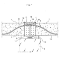
- FIG. 7 is a sectional view taken along the line C-C of FIG. 6B.
- a prestress strand 20 is continuously inserted in the sheath pipes 18 and the connecting sheath pipe 19.
- the strand 20 is continuously inserted in every sheath pipe 18 and connecting sheath pipe 19 through every span.
- the strand 20 may be inserted in the sheath pipe 18 and the connecting sheath pipe 19, after a space defined between the PSC-I beams 1 receives concrete, which will be described later herein.
- the strand 20, inserted in the every sheath pipe 18 and the connecting sheath pipe 19, is prestressed for transfer of prestressed force to the PSC-I beams 1, before or after a following concrete slab 16 is constructed on the PSC-I beams 1.
- FIG. 8 is an exploded perspective view of the structure for connecting the above-mentioned PSC-I beams 1.
- the steel brackets 6 of the PSC-I beams 1 are connected to each other, the concrete is filled in the space defined between the PSC-I beams 1 to form a concrete part 15.
- the aligned steel brackets 6, the bracket coupling plate 9 and the connecting sheath pipe 19 are embedded in the concrete part 15.
- FIG. 9 is a partially broken perspective view showing the beam connecting structure of FIG. 8 with the above-mentioned concrete part 15 filled in the space defined between the PSC-I beams 1.
- FIG. 9 is a partially broken perspective view showing the beam connecting structure of FIG. 8 with the above-mentioned concrete part 15 filled in the space defined between the PSC-I beams 1.
- FIG. 10 is a sectional view of a three-span bridge having the three PSC-I beams 1 connected to each other by the beam connecting structure of FIG. 9, in which the PC strand 20 arranged in the three PSC-I beams 1 is shown.
- the temporary support units 14, provided under the neighboring ends of the PSC-I beams 1 are removed, after the concrete part 15 is filled in the space defined between the PSC-I beams 1.
- the support bearing 3 on each of the piers 2 supports the bridge with the beam connecting structure of the present invention.
- the plurality of PSC-I beams 1 are firmly connected to each other by the beam connecting structure of the present invention.
- the bridge with the beam connecting structure forms a continuous beam system. Therefore, the bridge with the beam connecting structure reduces the positive moment generated in the PSC-I beams 1, thus reducing the size of the PSC-I beams 1 in comparison to a bridge with conventional beam connecting structure.
- the beam connecting structure of the present invention has the plurality of longitudinal connecting bolts 12 to withstand tensile stress generated by the negative moment. Furthermore, as described above with reference to FIG. 7, the PC strand 20 is continuously arranged in the bridge. Therefore, the PC strand 20 also withstands the tensile stress.
- the present invention provides a structure and a method of connecting a plurality of PSC-I beams to each other using steel brackets, bracket connecting plates, longitudinal connecting bolts, a connecting bottom plate and a concrete part, different from conventional structure for connecting the PSC-I beams using a plurality of reinforcing bars and a concrete part. That is, the beam connecting structure of the present invention more firmly connects the plurality of PSC-I beams to each other in comparison with the conventional beam connecting structure which cannot sufficiently connect the PSC-I beams to each other to form a simple beam system.
- the beam connecting structure of the present invention has a prestress strand which is arranged through entire spans. Therefore, the prestress force is evenly transferred to a concrete part filled in a space defined between the PSC-I beams, in addition to the PSC-I beams.
- the bridge with the beam connecting structure efficiently responds to a tensile stress generated by a negative moment.
- the bridge with the beam connecting structure according to the present invention has sufficient strength to respond the negative moment generated in the space defined between the PSC-I beams. Therefore, the bridge with the beam connecting structure of the present invention completely forms a continuous beam system. Thus, both a size of each of the PSC-I beams and construction costs are reduced in comparison with the conventional beam connecting structure with the simple beam system.
- the beam connecting structure of the present invention has only one support bearing on each of piers, different from the conventional beam connecting structure with at least two support bearings on each of the piers, the bridge is sufficiently supported on the piers.
Applications Claiming Priority (2)
| Application Number | Priority Date | Filing Date | Title |
|---|---|---|---|
| KR1020030095319A KR100621539B1 (ko) | 2003-12-23 | 2003-12-23 | 스틸브라켓에 의한 피.에스.씨-i빔의 연속결합방법 및 구조 |
| KR2003095319 | 2003-12-23 |
Publications (2)
| Publication Number | Publication Date |
|---|---|
| EP1548190A2 true EP1548190A2 (de) | 2005-06-29 |
| EP1548190A3 EP1548190A3 (de) | 2006-03-01 |
Family
ID=34545897
Family Applications (1)
| Application Number | Title | Priority Date | Filing Date |
|---|---|---|---|
| EP04012158A Withdrawn EP1548190A3 (de) | 2003-12-23 | 2004-05-22 | Konstruktion und Verfahren zur Verbindung von Type-I Spannbetonträgern unter Verwendung von Stahlkonsolen |
Country Status (5)
| Country | Link |
|---|---|
| US (1) | US20050144890A1 (de) |
| EP (1) | EP1548190A3 (de) |
| JP (1) | JP2005180162A (de) |
| KR (1) | KR100621539B1 (de) |
| CN (1) | CN100417771C (de) |
Cited By (3)
| Publication number | Priority date | Publication date | Assignee | Title |
|---|---|---|---|---|
| CN102733305A (zh) * | 2011-04-08 | 2012-10-17 | 江苏法尔胜新日制铁缆索有限公司 | 智能缆索用挡丝板 |
| CN103938736A (zh) * | 2014-05-04 | 2014-07-23 | 长沙远大住宅工业有限公司 | 预制叠合主次梁连接件及其连接结构 |
| CN104264795A (zh) * | 2014-08-14 | 2015-01-07 | 山东万斯达建筑工业化研究院有限公司 | 一种梁柱柔性连接装置及其施工方法 |
Families Citing this family (32)
| Publication number | Priority date | Publication date | Assignee | Title |
|---|---|---|---|---|
| EP1802813A4 (de) * | 2004-09-25 | 2013-03-20 | Univ Ajou Ind Coop Foundation | Verfahren zur herstellung eines spannbeton-hohlträgers(hpc-trägers) und einer gespleisten spannbeton-hohlträgerbrücke (s-hpc-brücke) |
| US7765764B2 (en) * | 2005-08-08 | 2010-08-03 | Sergio Zambelli | Device for connecting beams and pillars or similar structural elements |
| JP2007247267A (ja) * | 2006-03-16 | 2007-09-27 | Shoki:Kk | 架橋道路埋設用ケーブル保護シース部材および架橋道路埋設用ケーブル保護シース |
| JP4834197B2 (ja) * | 2006-07-14 | 2011-12-14 | 川崎重工業株式会社 | 連続桁橋の施工方法、合成床版および連続桁橋 |
| KR100868865B1 (ko) | 2007-02-23 | 2008-11-13 | 장신찬 | 연속 교량의 교각부에 헌치 블럭이 형성되는 프리스트레스트 콘크리트 빔 교량의 연속 공법 및 이를 이용한 교량의 연속화 구조 |
| JP2009041272A (ja) * | 2007-08-09 | 2009-02-26 | Ps Mitsubishi Construction Co Ltd | 橋梁の施工方法 |
| JP5367297B2 (ja) * | 2008-04-11 | 2013-12-11 | オリエンタル白石株式会社 | プレキャスト横桁とプレキャスト縦桁とを備えた橋梁およびその施工法 |
| JP5346523B2 (ja) * | 2008-08-25 | 2013-11-20 | 株式会社大林組 | 載置工法及び接合構造 |
| KR101078222B1 (ko) | 2008-12-17 | 2011-11-01 | 주식회사 포스코건설 | 벽체와 가설빔 간의 결합장치 |
| KR100950715B1 (ko) * | 2009-10-26 | 2010-03-31 | (주)대우건설 | 교량용 프리캐스트 코핑부의 시공 방법 |
| CN102086677A (zh) * | 2009-12-02 | 2011-06-08 | 张吉华 | 预制钢筋砼梁及钢筋砼柱与梁连接节点 |
| KR100991869B1 (ko) | 2010-02-09 | 2010-11-04 | 추태헌 | 단경간 및 다경간 피에스씨 거더교 및 그 시공방법 |
| KR101208231B1 (ko) | 2010-08-23 | 2012-12-04 | 권오근 | 2차 긴장재를 활용한 복부 파형강판 피에스씨 거더의 연속 지점부 시공방법 |
| CN102418381B (zh) * | 2010-09-28 | 2014-09-17 | 杨峰 | 钢梁与先张法预应力叠合梁相结合的房屋结构体系及其施工方法 |
| KR101124518B1 (ko) | 2011-06-15 | 2012-03-16 | 손석환 | 보강강재가 부착된 프리스트레스트 콘크리트 거더와 이의 시공방법 및 이를 이용한 연속교 및 이의 시공방법 |
| KR101453377B1 (ko) * | 2012-07-12 | 2014-10-23 | 우경건설 주식회사 | 코핑을 이용한 교량의 주거더 연결방법 |
| KR101530761B1 (ko) * | 2012-10-31 | 2015-06-22 | 이상규 | 라멘교의 슬라브 연결장치 및 그것을 구비한 라멘교 시공방법 |
| CN103362062A (zh) * | 2013-01-08 | 2013-10-23 | 韩志群 | 衔口梁 |
| KR101314854B1 (ko) * | 2013-04-02 | 2013-10-04 | 주식회사 알앤비텍 | 돌출 철근을 포함하는 거더 및 이를 이용한 교량 구조 |
| CN103266571B (zh) * | 2013-05-31 | 2015-10-28 | 中交二航局第四工程有限公司安徽分公司 | 一种过桥式钢绞线限位装置 |
| KR101709209B1 (ko) * | 2015-04-06 | 2017-02-22 | (주)나우기술 | 돌출형 케이블과 트러스구조로 변단면 구조를 보강하여 강성을 증대시킨 저형고 pc콘크리트빔 구조 |
| CN105113626B (zh) * | 2015-08-19 | 2018-01-05 | 广西矿建集团有限公司 | 现浇柱预制梁板结构施工方法 |
| CN105274939B (zh) * | 2015-09-10 | 2017-05-10 | 重庆市轨道交通设计研究院有限责任公司 | Pc轨道梁连接装置 |
| CN105178163B (zh) * | 2015-09-10 | 2017-07-04 | 重庆市轨道交通设计研究院有限责任公司 | 连续梁式轨道 |
| CN106481021A (zh) * | 2016-12-16 | 2017-03-08 | 福州大学 | 一种预应力组合梁结构及其施工方法 |
| PH12017000176A1 (en) * | 2017-06-16 | 2019-02-04 | Wookyung Tech Co Ltd | Psc girder bridge |
| CN107642163A (zh) * | 2017-10-23 | 2018-01-30 | 重庆凌锋投资管理有限公司 | 一种自支撑式钢板混凝土一体式梁板整浇结构及其施工方法 |
| JP6879634B2 (ja) * | 2018-11-06 | 2021-06-02 | 東洋建設株式会社 | プレキャスト梁部材の接合構造及び接合方法 |
| JP6747734B1 (ja) * | 2019-12-18 | 2020-08-26 | 黒沢建設株式会社 | Pc造3軸圧縮柱梁接合部のプレストレス導入法 |
| KR102341972B1 (ko) * | 2021-04-19 | 2021-12-21 | 김의헌 | 강연선 분배장치 및 강연선 분배장치가 적용된 psc 거더 |
| US11718964B2 (en) | 2021-09-13 | 2023-08-08 | Summit Precast Concrete, Lp | Bridge apparatus, systems and methods of construction |
| KR102619855B1 (ko) * | 2022-03-28 | 2023-12-29 | 유정태 | 단일 받침을 이용한 psc 연속교 시공 방법 |
Citations (3)
| Publication number | Priority date | Publication date | Assignee | Title |
|---|---|---|---|---|
| DE1256671B (de) * | 1964-04-18 | 1967-12-21 | Dyckerhoff & Widmann Ag | Verfahren zum Herstellen eines mehrfeldrigen vorgespannten Brueckentragwerks aus Spannbetonfertigbalken |
| GB1417027A (en) * | 1972-01-04 | 1975-12-10 | Soum R | Assemblies of prefabricated prestressed reinforced concrete elements |
| DE3114219A1 (de) * | 1981-04-08 | 1982-11-04 | Philipp Dipl.-Ing. 8014 Neubiberg Schreck | Gelenkkonstruktion fuer den hoch- und brueckenbau |
Family Cites Families (7)
| Publication number | Priority date | Publication date | Assignee | Title |
|---|---|---|---|---|
| US872728A (en) * | 1905-06-12 | 1907-12-03 | James Hartness | Machine for cutting screw-threads. |
| US2644497A (en) * | 1950-09-25 | 1953-07-07 | Emory M Wilmer | Clamp used in clamping plastic blocks together in plank construction |
| US3561179A (en) * | 1965-06-03 | 1971-02-09 | James M Young | Segmented concrete beam |
| US3906687A (en) * | 1973-10-09 | 1975-09-23 | Morris Schupack | Segmental precast concrete post-tensioned overpass bridges with cantilevered abutment |
| US5381635A (en) * | 1991-08-27 | 1995-01-17 | Royal Wall Systems, Inc. | Construction wall panel and panel structure |
| SE513987C2 (sv) * | 1999-07-16 | 2000-12-04 | Jacobsson & Widmark Ab | Betongplattkonstruktion samt sätt att bygga en sådan konstruktion |
| CN2477701Y (zh) * | 2001-05-24 | 2002-02-20 | 周志祥 | 桥梁由简支变连续的连结构造 |
-
2003
- 2003-12-23 KR KR1020030095319A patent/KR100621539B1/ko not_active IP Right Cessation
-
2004
- 2004-03-29 JP JP2004095062A patent/JP2005180162A/ja active Pending
- 2004-04-01 US US10/814,642 patent/US20050144890A1/en not_active Abandoned
- 2004-04-14 CN CNB2004100338067A patent/CN100417771C/zh not_active Expired - Fee Related
- 2004-05-22 EP EP04012158A patent/EP1548190A3/de not_active Withdrawn
Patent Citations (3)
| Publication number | Priority date | Publication date | Assignee | Title |
|---|---|---|---|---|
| DE1256671B (de) * | 1964-04-18 | 1967-12-21 | Dyckerhoff & Widmann Ag | Verfahren zum Herstellen eines mehrfeldrigen vorgespannten Brueckentragwerks aus Spannbetonfertigbalken |
| GB1417027A (en) * | 1972-01-04 | 1975-12-10 | Soum R | Assemblies of prefabricated prestressed reinforced concrete elements |
| DE3114219A1 (de) * | 1981-04-08 | 1982-11-04 | Philipp Dipl.-Ing. 8014 Neubiberg Schreck | Gelenkkonstruktion fuer den hoch- und brueckenbau |
Cited By (4)
| Publication number | Priority date | Publication date | Assignee | Title |
|---|---|---|---|---|
| CN102733305A (zh) * | 2011-04-08 | 2012-10-17 | 江苏法尔胜新日制铁缆索有限公司 | 智能缆索用挡丝板 |
| CN102733305B (zh) * | 2011-04-08 | 2014-07-09 | 江苏法尔胜缆索有限公司 | 智能缆索用挡丝板 |
| CN103938736A (zh) * | 2014-05-04 | 2014-07-23 | 长沙远大住宅工业有限公司 | 预制叠合主次梁连接件及其连接结构 |
| CN104264795A (zh) * | 2014-08-14 | 2015-01-07 | 山东万斯达建筑工业化研究院有限公司 | 一种梁柱柔性连接装置及其施工方法 |
Also Published As
| Publication number | Publication date |
|---|---|
| KR100621539B1 (ko) | 2006-09-13 |
| KR20050064049A (ko) | 2005-06-29 |
| CN100417771C (zh) | 2008-09-10 |
| US20050144890A1 (en) | 2005-07-07 |
| JP2005180162A (ja) | 2005-07-07 |
| CN1637215A (zh) | 2005-07-13 |
| EP1548190A3 (de) | 2006-03-01 |
Similar Documents
| Publication | Publication Date | Title |
|---|---|---|
| EP1548190A2 (de) | Konstruktion und Verfahren zur Verbindung von Type-I Spannbetonträgern unter Verwendung von Stahlkonsolen | |
| US8266751B2 (en) | Method to compress prefabricated deck units by tensioning supporting girders | |
| KR100776642B1 (ko) | 프리캐스트 콘크리트사장교 시공방법 | |
| CN110578289A (zh) | 一种新型钢混组合梁剪力连接键 | |
| KR100529518B1 (ko) | 솔 플레이트를 이용한 프리스트레스트 콘크리트 빔 중간 지점부 연속화 구조 및 방법 | |
| KR101013009B1 (ko) | 정착판 연결장치와 이를 이용한 피에스씨 거더교의 연속화 시공방법 | |
| KR100785634B1 (ko) | 프리스트레스트 콘크리트 합성빔 교량의 연속화 구조 및 그공법 | |
| KR100690395B1 (ko) | 프리스트레스 콘크리트 빔의 연속화 방법 | |
| KR100374017B1 (ko) | 연속 프리플렉스 빔 교량구조물 및 그 연속화 시공방법 | |
| KR101714159B1 (ko) | 전도방지장치가 구비된 휨모멘트 전달 분리장치 및 이를 이용한 라멘교 | |
| JP4086863B2 (ja) | 複径間桁橋における連続桁構造 | |
| KR20050018358A (ko) | 빔 연결부재와 강재가로보를 이용한 프리캐스트 피에스씨빔의 연속화 구조 및 이를 이용한 교량시공방법 | |
| KR101001443B1 (ko) | 탈부착 가능한 정착장치를 이용한 합성거더교량의 주거더 연속화 공법 | |
| KR200384805Y1 (ko) | 프리스트레스 콘크리트 빔의 연속화 구조 | |
| JP2003138523A (ja) | 張弦桁橋の構築方法 | |
| KR102033052B1 (ko) | Src 거더를 이용한 충전강관 트러스교의 지점부 시공방법 | |
| JP7266808B1 (ja) | 主桁連続化剛結合工法 | |
| KR20190031790A (ko) | 노후교량 보강공법 | |
| CN114703735B (zh) | 一种多跨上承式连续拱桥拱顶构造 | |
| JP2003049487A (ja) | 鋼部材とコンクリート部材との接合構造 | |
| KR102619855B1 (ko) | 단일 받침을 이용한 psc 연속교 시공 방법 | |
| JPH08253912A (ja) | 橋梁構造 | |
| CN212103625U (zh) | 可拆装梁式桥梁主梁结构 | |
| CN110820532B (zh) | 可重复拆装梁式桥主梁结构的设计实施方法 | |
| KR200345792Y1 (ko) | 스틸브라켓에 의한 피.에스.씨-i빔 |
Legal Events
| Date | Code | Title | Description |
|---|---|---|---|
| PUAI | Public reference made under article 153(3) epc to a published international application that has entered the european phase |
Free format text: ORIGINAL CODE: 0009012 |
|
| AK | Designated contracting states |
Kind code of ref document: A2 Designated state(s): AT BE BG CH CY CZ DE DK EE ES FI FR GB GR HU IE IT LI LU MC NL PL PT RO SE SI SK TR |
|
| AX | Request for extension of the european patent |
Extension state: AL HR LT LV MK |
|
| PUAL | Search report despatched |
Free format text: ORIGINAL CODE: 0009013 |
|
| AK | Designated contracting states |
Kind code of ref document: A3 Designated state(s): AT BE BG CH CY CZ DE DK EE ES FI FR GB GR HU IE IT LI LU MC NL PL PT RO SE SI SK TR |
|
| AX | Request for extension of the european patent |
Extension state: AL HR LT LV MK |
|
| 17P | Request for examination filed |
Effective date: 20060218 |
|
| AKX | Designation fees paid |
Designated state(s): AT BE BG CH CY CZ DE DK EE ES FI FR GB GR HU IE IT LI LU MC NL PL PT RO SE SI SK TR |
|
| STAA | Information on the status of an ep patent application or granted ep patent |
Free format text: STATUS: THE APPLICATION IS DEEMED TO BE WITHDRAWN |
|
| 18D | Application deemed to be withdrawn |
Effective date: 20071203 |