BACKGROUND OF THE INVENTION
Field of the Invention
The present invention relates generally to a structure and a method of connecting
I-type prestressed concrete beams (hereinafter referred to simply as PSC-I beams) using
steel brackets, and more particularly, to a structure and a method of connecting a
plurality of PSC-I beams, separately precasted on the ground, to each other using steel
brackets.
Description of the Related Art
FIG. 1A is a side view of a two-span bridge with a conventional structure for
connecting two I-type prestressed concrete beams 1 (PSC-I beams) to each other. The
two PSC-I beams 1, used in the conventional two-span bridge of FIG. 1A, are separately
precasted on the ground. Thereafter, each of the PSC-I beams 1 is independently placed
between a pier 2 and a pair of support grounds, which support both ends of the two-span
bridge, to form a simple beam system. At this time, the two PSC-I beams 1 are
connected to each other by only a concrete slab 16 which is constructed on the two PSC-I
beams 1. Otherwise, the plurality of PSC-I beams 1 may be connected to each other by
another conventional beam connecting structure, as shown in FIG. 1B.
To construct a bridge with the conventional beam connecting structure of FIG.
1B, each of PSC-I beams 1 is precasted, so that a plurality of reinforcing bars 17 are
embedded in each of the PSC-I beams 1 while an end of each of the reinforcing bars 17
is exposed from an end of the PSC-I beam 1 to a predetermined distance. Thereafter,
each of the PSC-I beams 1 are placed between the pair of support grounds and the piers
2. There is a predetermined space between ends of the two PSC-I beams 1 placed on the
piers 2. When the PSC-I beams 1 are linearly arranged, the reinforcing bars 17 exposed
from an end of one of the PSC-I beams 1 are respectively coupled to the reinforcing bars
17 exposed from an end of a neighboring PSC-I beam 1. Thereafter, concrete is filled in
each of the predetermined space defined between the ends of the PSC-I beams 1 to form
a concrete part 15. The concrete slab 16 is, thereafter, integrally constructed on the PSC-I
beams 1 and the concrete parts 15.
However, in the conventional structure for connecting the PSC-I beams, each of
the PSC-I beams 1 has a role as the simple beam system. That is, an additional support
bearing 3 is provided under each of both ends of the PSC-I beam 1 to support the PSC-I
beams 1 on the pier 2 and the support grounds. Therefore, at least two support bearings
3 must be placed on the pier 2. At this time, ideally, a reaction force against a live load
must be evenly applied to the two support bearings 3 on the pier 2. However, in reality,
one of the two support bearings 3 has a negative (-) reaction force, and the other support
bearing 3 has an excessive positive (+) reaction force. Therefore, the support bearing 3,
which has the excessive positive (+) reaction force, must have a larger capacity. Thus,
the conventional beam connecting structure imposes excessive constructing costs on
users.
In the bridge with the conventional beam connecting structure of FIG. 1B, the
concrete part 15 is filled in the space defined between the PSC-I beams. At this time, a
cold joint is undesirably generated on each of junctions of both ends of the concrete part
15 and the ends of the PSC-I beams 1. Therefore, a crack may be generated around the
cold joint by the live load. As described above, when the crack is generated around the
cold joint, the PSC-I beams 1 are not firmly connected to each other. Thus, structural
defect may be caused in the bridge with the conventional beam connecting structure.
In the meantime, a negative moment is generated around parts of the PSC-I
beams, which are supported on the pier 2. However, the conventional beam connecting
structure does not have sufficient strength for resistance against the above-mentioned
negative moment. Therefore, tensile stress is generated around a part of the concrete
slab 16 which is positioned on the concrete part 15 filled between the PSC-I beams.
Thus, a crack is undesirably caused around the part of the concrete slab 16, which is
positioned on the concrete part 15, by the above-mentioned tensile stress.
SUMMARY OF THE INVENTION
Accordingly, the present invention has been made keeping in mind the above
problems occurring in the prior art, and an object of the present invention is to provide a
structure and a method of connecting a plurality of PSC-I beams to each other using end
plates and steel brackets which have higher structural durability, different from a
conventional structure for connecting the plurality of PSC-I beams using only the
reinforcing bars and concrete, so that the plurality of PSC-I beams are firmly connected
to each other.
Another object of the present invention is to provide an structure and method of
connecting the plurality of PSC-I beams, which has only one support bearing on each of
piers to support the PSC-I beams, thus solving the disadvantages caused by using the
plurality of support bearings in the prior art.
In an aspect, the present invention provides an structure for connecting a plurality
of PSC-I beams, each having a sheath pipe therein, to each other. The beam connecting
structure includes an end plate mounted on each of both ends of each of the PSC-I
beams, with a through hole provided on an upper portion of the end plate to correspond
to the sheath pipe embedded in each of the PSC-I beams; a steel bracket integrally
provided on the end plate to be perpendicular to the end plate, so that the steel brackets
of the neighboring end plates of the PSC-I beams are aligned with each other while the
PSC-I beams are arranged linearly; a bracket coupling plate to integrally couple the
aligned steel brackets to each other; a bottom connecting plate provided on lower ends of
the aligned steel brackets to connect the steel brackets to each other; a connecting sheath
pipe provided between the PSC-I beams so that both ends of the connecting sheath pipe
are respectively inserted into the through holes of the neighboring end plates of the PSC-I
beams while the PSC-I beams are arranged linearly, thereby the sheath pipes of the
PSC-I beams are connected to each other; a prestress strand inserted in the sheath pipes
of the PSC-I beams and the connecting sheath pipe while the PSC-I beams are linearly
connected to each other, the PC strand being prestressed in the sheath pipes and the
connecting sheath pipe for transfer of prestress to the PSC-I beams; and a concrete part
filled in a space between the PSC-I beams to embed the aligned steel brackets, the
bracket coupling plate and the connecting sheath pipe in the concrete part.
In another aspect, the present invention provides a method of connecting a
plurality of PSC-I beams, each having a sheath pipe therein, to each other. The beam
connecting method includes mounting an end plate on each of both ends of each of the
PSC-I beams, with a through hole provided on an upper portion of the end plate to
correspond to the sheath pipe embedded in each of the PSC-I beams; providing
integrally a steel bracket on the end plate to be perpendicular to the end plate; placing the
PSC-I beams on a plurality of piers while the steel brackets of the neighboring end plates
of the PSC-I beams are aligned with each other on a bottom connecting plate placed on a
support bearing mounted on each of the plurality of piers; mounting the aligned steel
brackets of the neighboring end plates of the PSC-I beams to the bottom connecting
plate to connect the steel brackets to each other; mounting a bracket coupling plate to the
aligned steel brackets to integrally couple the aligned steel brackets to each other;
placing a longitudinal connecting bolt on upper portions of the aligned steel brackets to
connect the steel brackets to each other; placing a connecting sheath pipe between the
PSC-I beams so that both ends of the connecting sheath pipe are respectively inserted
into the through holes of the neighboring end plates of the PSC-I beams while the PSC-I
beams are arranged linearly, thereby the sheath pipes are connected to each other;
inserting a prestress strand (PC strand) in the sheath pipes of the PSC-I beams and the
connecting sheath pipe while the PSC-I beams are linearly connected to each other, and
prestressing the PC strand for transfer of prestress to the PSC-I beams; and filling
concrete in a space defined between the PSC-I beams to form a concrete part, thus
embedding the aligned steel brackets, the bracket coupling plate and the connecting
sheath pipe in the concrete part.
BRIEF DESCRIPTION OF THE DRAWINGS
The above and other objects, features and other advantages of the present
invention will be more clearly understood from the following detailed description taken
in conjunction with the accompanying drawings, in which:
DESCRIPTION OF THE PREFERRED EMBODIMENTS
Hereinafter, embodiments of the present invention will be described in detail
with reference to the attached drawings.
Reference now should be made to the drawings, in which the same reference
numerals are used throughout the different drawings to designate the same or similar
components.
FIG. 2 is a sectional view of one of a plurality of I-type prestressed concrete
beams 1 (PSC-I beams) connected to each other with a structure for connecting the
plurality of PSC-I beams, according to an embodiment of the present invention. FIG. 3
is a partially broken perspective view of the PSC-I beam 1 of FIG. 2, in which a part
around an end of the PSC-I beam 1 is shown. As shown in FIGS. 2 and 3, in the beam
connecting structure according to the present invention, each of the PSC-I beams, made
of concrete, has a sheath pipe 18 therein. That is, when the PSC-I beam 1 is produced,
the sheath pipe 18 is previously embedded in the concrete. The sheath pipe 18 receives
therein a prestress strand. The beam connecting structure of the present invention
includes an end plate 4 which is mounted on at least one of both ends of each of the
PSC-I beams 1. In detailed, a plurality of anchor bolts 7 are previously embedded in the
concrete of at least one of both ends of each of the PSC-I beams 1, while each of the
PSC-I beam 1 is precasted. Thereafter, the end plate 4 is fitted over ends of the plurality
of anchor bolts 7. A nut 13 is, thereafter, tightened to each of the plurality of anchor
bolts 7 to couple the end plate 4 to the end of the PSC-I beam 1.
In the beam connecting structure of the present invention, two steel brackets 6 are
integrally provided on each of the end plates 4 by welding to be perpendicular to the end
plate 4. A through hole 5 is provided on an upper portion of the end plate 4 to
correspond to the sheath pipe 18 which is embedded in each of the PSC-I beams 1. A
plurality of bolt holes are provided on each of the steel brackets 6, so that the steel
bracket 6 is coupled to a following bracket coupling plate 9 by a plurality of coupling
bolts 10 and coupling nuts 10a which will be described later herein.
FIG. 4A is a side view showing a step for connecting the two PSC-I beams 1 of
FIG. 2 to each other, in which the two PSC-I beams 1 are placed on a pier 2 while the
two PSC-I beams 1 are arranged linearly. FIG. 4B is a sectional view taken along the
line A-A of FIG. 4A.
As shown in FIGS. 4A and 4B, a support bearing 3 is provided on the pier 2
before the PSC-I beams 1 are placed over the pier 2. A plurality of temporary support
units 14 are provided around the support bearing 3 on the pier 2 to support the
neighboring ends of the PSC-I beams 1 on the pier 2. A bottom connecting plate 8 is
placed on the support bearing 3. Thereafter, the PSC-I beams 1, separately precasted on
the ground, are placed over the pier 2 while the neighboring ends of the PSC-I beams 1
are supported on the plurality of temporary support units 14. At this time, the steel
brackets 6 of the neighboring end plates 4 of the PSC-I beams 1 are aligned with each
other on the bottom connecting plate 8. The steel brackets 6 of the neighboring end
plates 4 are mounted at lower ends thereof to the bottom connecting plate 8 by welding,
so that the steel brackets 6 are connected to each other.
FIG. 5 is a side view showing a step for connecting the PSC-I beams 1 of FIG. 2
executed after the connecting process shown in FIG. 4A, in which a bracket connecting
plate 9 and a connecting sheath pipe 19 are provided between the neighboring end plates
4 of the PSC-I beams 1.
As shown in FIG. 5, the connecting sheath pipe 19 is provided between the PSC-I
beams 1 so that both ends of the connecting sheath pipe 19 are respectively inserted
into the through holes 5 which are respectively provided on the upper portions of the
neighboring end plates 4 of the PSC-I beams 1, while the PSC-I beams are arranged
linearly. By placing of the connecting sheath pipe 19, the sheath pipes 18 of the PSC-I
beams 1 are connected to each other.
In the meantime, the two bracket coupling plates 9 are respectively provided on
both sides of the aligned steel brackets 6 of the neighboring end plates 4. The bracket
coupling plates 9 and the aligned steel brackets 6 are integrally coupled to each other by
the plurality of coupling bolts 10 and the plurality of nuts 10a. Therefore, the aligned
steel brackets 6 are connected to each other by the bottom connecting plate 3, in addition
to the bracket coupling plates 9.
FIG. 6A is a side view showing a state of the structure for connecting the PSC-I
beams 1 after the connecting step shown in FIG. 5 is executed, in which the aligned steel
brackets 6 are connected to each other by the bracket connecting plate 9. FIG. 6B is a
sectional view taken along the line B-B of FIG. 6A. As show in FIGS. 6A and 6B, the
aligned steel brackets 6 are also connected to each other by a plurality of longitudinal
connecting bolts 12. That is, a bolt holding unit 11 is provided on an upper end of each
of the steel brackets 6 of the PSC-I beams 1. A connecting nut 21 is tightened to each of
the longitudinal connecting bolts 12 while the longitudinal connecting bolt 12 passes
through both the bolt holding units 11 of the aligned steel brackets 6. Thus, the steel
brackets 6 are more firmly connected to each other by the longitudinal connecting bolts
12 and the connecting nuts 21. At this time, the bolt holding unit 11 is mounted to an
upper support plate 22 which is provided on the upper end of each of the steel brackets
6.
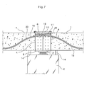
FIG. 7 is a sectional view taken along the line C-C of FIG. 6B. As described
above, in a state in that the sheath pipes 18 of the PSC-I beams 1 are connected to each
other by the connecting sheath pipe 19, a prestress strand 20 is continuously inserted in
the sheath pipes 18 and the connecting sheath pipe 19. Particularly, even when the PSC-I
beams 1 are placed over at least two spans, the strand 20 is continuously inserted in
every sheath pipe 18 and connecting sheath pipe 19 through every span. At this time,
the strand 20 may be inserted in the sheath pipe 18 and the connecting sheath pipe 19,
after a space defined between the PSC-I beams 1 receives concrete, which will be
described later herein. The strand 20, inserted in the every sheath pipe 18 and the
connecting sheath pipe 19, is prestressed for transfer of prestressed force to the PSC-I
beams 1, before or after a following concrete slab 16 is constructed on the PSC-I beams
1.
FIG. 8 is an exploded perspective view of the structure for connecting the above-mentioned
PSC-I beams 1. After, as shown in FIG. 7, the steel brackets 6 of the PSC-I
beams 1 are connected to each other, the concrete is filled in the space defined between
the PSC-I beams 1 to form a concrete part 15. Thus, the aligned steel brackets 6, the
bracket coupling plate 9 and the connecting sheath pipe 19 are embedded in the concrete
part 15. FIG. 9 is a partially broken perspective view showing the beam connecting
structure of FIG. 8 with the above-mentioned concrete part 15 filled in the space defined
between the PSC-I beams 1. FIG. 10 is a sectional view of a three-span bridge having
the three PSC-I beams 1 connected to each other by the beam connecting structure of
FIG. 9, in which the PC strand 20 arranged in the three PSC-I beams 1 is shown. As
shown in FIGS. 9 and 10, the temporary support units 14, provided under the
neighboring ends of the PSC-I beams 1, are removed, after the concrete part 15 is filled
in the space defined between the PSC-I beams 1. Thus, only the support bearing 3 on
each of the piers 2 supports the bridge with the beam connecting structure of the present
invention.
As described above, the plurality of PSC-I beams 1 are firmly connected to each
other by the beam connecting structure of the present invention. Thus, the bridge with
the beam connecting structure forms a continuous beam system. Therefore, the bridge
with the beam connecting structure reduces the positive moment generated in the PSC-I
beams 1, thus reducing the size of the PSC-I beams 1 in comparison to a bridge with
conventional beam connecting structure.
Generally, in case of bridges with continuous beam systems, the positive
moment is reduced. However, negative moments are generated in upper portions of the
bridges by dead loads caused by the weight of the concrete slab 16 and additional
asphalt pavements. In above state, when cars pass through the bridges, the negative
moments are increased.
In the bridge with the beam connecting structure according to the present
invention, the above-mentioned negative moment is also generated in the bridge.
However, the beam connecting structure of the present invention has the plurality of
longitudinal connecting bolts 12 to withstand tensile stress generated by the negative
moment. Furthermore, as described above with reference to FIG. 7, the PC strand 20 is
continuously arranged in the bridge. Therefore, the PC strand 20 also withstands the
tensile stress.
As described above, the present invention provides a structure and a method of
connecting a plurality of PSC-I beams to each other using steel brackets, bracket
connecting plates, longitudinal connecting bolts, a connecting bottom plate and a
concrete part, different from conventional structure for connecting the PSC-I beams
using a plurality of reinforcing bars and a concrete part. That is, the beam connecting
structure of the present invention more firmly connects the plurality of PSC-I beams to
each other in comparison with the conventional beam connecting structure which cannot
sufficiently connect the PSC-I beams to each other to form a simple beam system.
Furthermore, the beam connecting structure of the present invention has a
prestress strand which is arranged through entire spans. Therefore, the prestress force is
evenly transferred to a concrete part filled in a space defined between the PSC-I beams,
in addition to the PSC-I beams. Thus, the bridge with the beam connecting structure
efficiently responds to a tensile stress generated by a negative moment.
In addition, the bridge with the beam connecting structure according to the
present invention has sufficient strength to respond the negative moment generated in
the space defined between the PSC-I beams. Therefore, the bridge with the beam
connecting structure of the present invention completely forms a continuous beam
system. Thus, both a size of each of the PSC-I beams and construction costs are reduced
in comparison with the conventional beam connecting structure with the simple beam
system.
Furthermore, even though the beam connecting structure of the present invention
has only one support bearing on each of piers, different from the conventional beam
connecting structure with at least two support bearings on each of the piers, the bridge is
sufficiently supported on the piers.
Although the preferred embodiments of the present invention have been
disclosed for illustrative purposes, those skilled in the art will appreciate that various
modifications, additions and substitutions are possible, without departing from the scope
and spirit of the invention as disclosed in the accompanying claims.