EP1547485A2 - Kamera mit Haltegurt - Google Patents
Kamera mit Haltegurt Download PDFInfo
- Publication number
- EP1547485A2 EP1547485A2 EP04293132A EP04293132A EP1547485A2 EP 1547485 A2 EP1547485 A2 EP 1547485A2 EP 04293132 A EP04293132 A EP 04293132A EP 04293132 A EP04293132 A EP 04293132A EP 1547485 A2 EP1547485 A2 EP 1547485A2
- Authority
- EP
- European Patent Office
- Prior art keywords
- belt
- section
- camera body
- hand
- camera
- Prior art date
- Legal status (The legal status is an assumption and is not a legal conclusion. Google has not performed a legal analysis and makes no representation as to the accuracy of the status listed.)
- Withdrawn
Links
Images



Classifications
-
- H—ELECTRICITY
- H04—ELECTRIC COMMUNICATION TECHNIQUE
- H04N—PICTORIAL COMMUNICATION, e.g. TELEVISION
- H04N23/00—Cameras or camera modules comprising electronic image sensors; Control thereof
-
- A—HUMAN NECESSITIES
- A45—HAND OR TRAVELLING ARTICLES
- A45C—PURSES; LUGGAGE; HAND CARRIED BAGS
- A45C13/00—Details; Accessories
- A45C13/30—Straps; Bands
-
- G—PHYSICS
- G03—PHOTOGRAPHY; CINEMATOGRAPHY; ANALOGOUS TECHNIQUES USING WAVES OTHER THAN OPTICAL WAVES; ELECTROGRAPHY; HOLOGRAPHY
- G03B—APPARATUS OR ARRANGEMENTS FOR TAKING PHOTOGRAPHS OR FOR PROJECTING OR VIEWING THEM; APPARATUS OR ARRANGEMENTS EMPLOYING ANALOGOUS TECHNIQUES USING WAVES OTHER THAN OPTICAL WAVES; ACCESSORIES THEREFOR
- G03B17/00—Details of cameras or camera bodies; Accessories therefor
- G03B17/56—Accessories
- G03B17/563—Camera grips, handles
-
- H—ELECTRICITY
- H04—ELECTRIC COMMUNICATION TECHNIQUE
- H04N—PICTORIAL COMMUNICATION, e.g. TELEVISION
- H04N23/00—Cameras or camera modules comprising electronic image sensors; Control thereof
- H04N23/50—Constructional details
Definitions
- the present invention relates to a camera equipped with a grip belt.
- Cameras such as, for example, video cameras are well known.
- a video camera is provided with a camera body formed in a flat rectangular shape of a length from front to back and height from top to bottom greater than the thickness from left to right, a photographing optical system provided so as to be exposed from the upper part of a front surface of the camera body, photographing operation members provided at the upper front part of the right side surface of the camera body, and a grip belt provided at the right side surface of the camera body.
- the ends of this kind of grip belt are connected to locations at the front part and rear part of the side surface of the camera body. The palm of the right hand is then made to face the side surface of the camera body.
- the four fingers with the exception of the thumb are then inserted into a space formed between the grip belt and the side surface of the camera body with the back of the right hand facing the inside of the grip belt so that, for example, the thumb is positioned at the lower part or the rear part of the camera body.
- the fingers with the exception of the thumb are then positioned at the upper part or front part of the camera body.
- photographing operation members can then be operated while the camera body is gripped using the thumb and the other fingers (for example, refer to Japanese Patent Application Publication No. 2001-53987
- the fingertips are not always positioned at appropriate locations for gripping the camera when the hand is inserted between the camera body side surface and the grip belt. This is disadvantageous with regards to gripping the camera body securely. And the fingers are not always positioned at locations where it is easy to operate the photographing operation members, so this is also disadvantageous with regards to operation.
- the hand is inserted between the camera body side surface and the grip belt, the inserted hand becomes restrained by the camera body side surface and the grip belt. More specifically, the palm of the hand is always restrained at the side surface of the camera body and there is no longer any degree of freedom for the palm of the hand, which puts a limit on improvements to handling and manageability.
- the present invention sets out to resolve this situation.
- the present invention provides a camera where it is easy for a user to grip a camera body, it is easy for the user to operate, and it is advantageous for improving handling and manageability.
- a camera according to the present invention includes: a camera body formed in a flat rectangular shape of a length from front to back and a height from top to bottom greater than a thickness from left to right; a photographing optical system provided so as to be exposed from the upper part of a front surface of the camera body; a photographing operation member provided at the upper front part of the right side surface of the camera body; and a grip belt provided at the right side surface of the camera body.
- the grip belt has a first belt attached to the lower part of the front part of the camera body so as to be hung down from the lower part with a belt connecting link being attached to the lower end of the belt, and a second belt connected to the belt connecting link.
- the second belt has a hand insertion section of a size that allows insertion of four fingers of the right hand with the exception of the thumb and the palm portion of the hand corresponding to the four fingers.
- the hand insertion section is provided by an inside belt section positioned at the right side surface of the camera body and an outside belt section positioned to the outside of the inside belt section.
- One end of the inside belt section in the longitudinal direction is connected to the belt connecting link and the other end in the longitudinal direction is attached to the rear part of the right side surface of the camera body.
- the hand insertion section therefore takes on a long shape in a direction from the front to the rear of the camera body on the right side surface of the camera body due to the inside belt section, and is tilted so that the rear end of the hand insertion section is positioned above the front end of the hand insertion section.
- the four fingers of the right hand with the exception of the thumb and the palm part of the hand corresponding to the four fingers are then inserted through the hand insertion section so that the tip of the thumb comes into contact with the rear surface of the camera, and the camera is held with at least the tips of the middle finger and third finger coming into contact with the front surface of the camera body. It is then possible to operate photographing operation members using the index finger.
- the hand is inserted into a hand insertion section where a substantial range of freedom of movement with respect to the right side surface of the camera body is ensured by the first belt.
- a substantial degree of freedom for the palm of the hand can be ensured. It is also easy for the fingertips to reach appropriate locations for gripping the camera body which enables the camera body to be securely held. The fingers can also easily reach locations where it is easy to operate the photographing operation members which is advantageous in operating photographing operation members provided at the upper part of the front part of the right side surface of the camera body.
- the advantages of making the camera body easy to grip, making operation straightforward, and improving handling and manageability is achieved by providing a hand insertion section of a size capable of enabling four fingers and the palm corresponding to the four fingers to be inserted through at a grip belt.
- left and right of the camera is taken to be the left and right of the camera as viewed from the rear.
- the camera of this embodiment is a video camera 100 capable of recording moving images and still images.
- the video camera 100 is equipped with a camera body 10.
- a camera mechanism and a video mechanism are built-in in an integrated manner to within the camera body 10.
- the camera body 10 is formed in a flat rectangular shape of a length from front to back and a height from top to bottom greater than a thickness from left to right.
- the camera body 10 is formed of dimensions where the height from top to bottom is greater than the length from front to rear so that the video camera 100 is a vertical type.
- the camera body 10 is provided with a photographing optical system 12 positioned so as to be exposed from the upper part of a front surface 1002 of the camera body 10.
- a viewfinder 14 is provided at the upper part of a rear surface 1004 of the camera body 10.
- a power switch 16 and a start/stop button 18 for starting and stopping moving image recording are provided at locations on the rear surface 1004 below the viewfinder 14.
- a zoom lever 20 is arranged in a swingably manner at an upper part of the front part of the right side surface 1012 of the camera body 10 as shown in FIG. 3, and a shutter button 22 for taking still images is provided at a location to the rear of the zoom lever 20.
- the power switch 16, start/stop button 18, zoom lever 20 and shutter button 22 constitute the photographing operation member of the present invention.
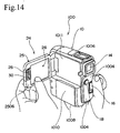
- a display unit 24 rectangular in shape is provided in a manner capable of opening and closing at an upper half of the left side surface 1010 of the camera body 10 and a recess 1011 for housing the display unit 24 when closed is also provided.
- the display unit 24 is equipped with a case 25 and a display 26.
- the case 25 is rectangular in shape and is an oblong rectangle with the dimension from front to back being greater than the dimension from top to bottom and the front part is connected so as to be openable and closable at a hinge 2502 provided at an upper part of the front part of the left side surface 1010 of the camera body 10.
- connection of the case 25 using the hinge 2502 is such as to enable rotation about a first axis extending in a vertical direction of the camera body 10 and rotation about a second axis of rotation orthogonal to the first axis.
- the case 25 is provided with an outer surface 2504 positioned on one side in the thickness direction, an inner surface 2506 positioned at the other side in the thickness direction, and a recess provided at the inner surface 2506.
- the outer surface 2504 of the case 25 is constructed so as to form part of the surface of the camera body 10 continuing on from the surface of the camera body 10 with the display 25 closed.
- the display 26 is housed in the recess.
- the inner surface of the case constitutes a rectangular frame surface extending about the periphery of the display.
- the display 26 is for displaying images including moving images, still images and characters etc.
- the display is comprised of, for example, a hybrid liquid crystal display and a backlight for illuminating the hybrid liquid crystal display.
- a hybrid liquid crystal display and a backlight for illuminating the hybrid liquid crystal display.
- both displaying where the hybrid liquid crystal display is illuminated by the backlight and displaying where the backlight is extinguished and does not illuminate the hybrid liquid crystal display but rather the hybrid liquid crystal display is illuminated using light from the peripheral surroundings are possible.
- a backlight button 28 is provided on an upper side and a start/stop button 30 is provided on a lower side at a location positioned on the opposite side to the hinge 2502 of the inner surface 2506, and more specifically, at a location positioned on the opposite side to the hinge 2502 in a direction from the front to the rear of the case.
- the backlight button 28 is for turning the backlight of the display 26 on and off and the start/stop button 30 starts and stops recording of moving images in the same way as the start/stop button 18.
- the backlight button 28 and the start/stop button 30 are provided located at a position on the opposite side to the hinge 2502 of the inner surface 2506 of the display unit 24.
- the backlight button 28 and the start/stop button 30 are inevitably positioned in a location where operation by the fingertips of the left hand of the user is straightforward, and it is therefore advantageous for improving ease of operation.
- the edge of the case 25 of the display unit 24 is gripped in the thickness direction using the thumb and fingers of the left hand at a position in the vicinity of the backlight button 28 and the start/stop button 30, so that it is possible to prevent camera shake and achieve a stable photographing posture.
- the switches provided at the case 25 of the display unit 24 are by no means limited to the backlight 28 and the start/stop button 30, and may also be, for example, a zoom operation switch or a shutter switch etc. Further, some or all of these switches may also be implemented as touch switches provided on the screen surface of the display 26.
- a grip belt 40 is provided at the right side surface 1012 of the camera body 10, as shown in FIG. 1 and FIG. 3.
- the grip belt 40 has a first belt 42 and a second belt 44.
- the first belt 42 and the second belt 44 are made, for example, of flexible synthetic resin material.
- One end in the longitudinal direction of the first belt 42 is attached to a mounting section 1014 at a lower part of the front part of the right side surface 1012 of the camera body 10, and the other end of the belt 42 is attached to a rectangular hoop-shaped belt connecting link 4202, with a pad 4204 being attached to the first belt 42 with the exception of both ends in the longitudinal direction.
- the pad 4204 is formed, for example, from a flexible material such as artificial leather, thick cloth, flexible synthetic resin, or flexible rubber, etc.
- the second belt 44 is provided so as to be joined to the belt connecting link 4202.
- a hand insertion section 48 of a size that allows insertion of four fingers of the right hand with the exception of the thumb and the palm portion corresponding to the four fingers to be inserted within is provided as a result of providing an inside belt section 4402 positioned at the right side surface 1012 of the camera body 10 and an outside belt section 4404 positioned at the outside of the inside belt section 4402.
- One end in the longitudinal direction of the inside belt section 4402 is connected to the belt connecting link 4202.
- the other end in the longitudinal direction of the inside belt section 4402 is attached to the rear part of the right side surface 1012 of the camera body 10.
- the other end of the inside belt section 4402 is attached at a rear part of the right side surface 1012 of the camera body 10 and at a location above the mounting section 1014 where the first belt 42 is attached to the camera body 10. Further, in this embodiment, the other end of the inside belt section 4402 is attached' in a detachable manner to a rear part of the right side surface 1012 of the camera body 10. Describing this in more detail, as shown in FIG. 4, FIG. 5 and FIG.
- an engaging/disengaging mechanism 46 constituted by an oblong engaging hole 4602 and a release lever 4604 is provided at the rear part of the right side surface 1012 of the camera body 10, and a clasp 4406 engaging and disengaging with the engaging/disengaging mechanism 46 is provided at the inside belt section 4402 as shown in FIG. 8.
- an engaging piece 4408 of the clasp 4406 is inserted into the engaging hole 4602 as the inside belt section is inclined so that the front part of the inside belt section 4402 becomes higher than the rear part. Then, as shown in FIG. 6, after tilting so that the front part of the inside belt section 4402 becomes lower than the rear part, the engaging piece 4408 engages with the engaging/disengaging mechanism 46.
- the release lever 4604 is operated from the inclined state of the inside belt section 4402 as shown in FIG. 6, and when tilting takes place so that the front part of the inside belt section 4402 becomes higher than the rear part as shown in FIG. 5, the engaging piece 4408 is released from the engaging/disengaging mechanism 46.
- Various structures that are well known in the related art may be adopted for the structures of the engaging/disengaging mechanism 46 and the clasp 4406.
- the hand insertion section 48 takes on a long shape in a direction from the front to the rear of the camera body 10 at the right side surface 1012 of the camera body 10 and the rear end of the hand insertion section 48 is inclined so as to be positioned higher than the front end of the hand insertion section 48.
- the front part in the longitudinal direction of the hand insertion section 48 is positioned below the camera body 10, a middle section in the longitudinal direction of the hand insertion section 48 is positioned in the vicinity of the lower surface of the camera body 10, and the rear part of the hand insertion section 48 is positioned to the right side surface 1012 of the camera body 10.
- the hand insertion section 48 is such that the front end of the hand insertion section 48 is capable of moving in a vertical direction and in a direction away from the right side surface 1012 of the camera body 10 by taking a location at the rear end attached to the engaging/disengaging mechanism 46 as a fulcrum and a degree of freedom can therefore be ensured.
- the front end of the hand insertion section 48 is connected to the lower end of the first belt 42.
- the front end of the hand insertion section 48 is therefore capable of moving within a range corresponding to the range of movement of the first belt 42 by taking the mounting section 1014 as a fulcrum and a larger degree of freedom can therefore be ensured for the hand insertion section 48.
- a back hand pad 50 is attached at the outside belt section 4404.
- the back hand pad 50 is made, for example, from a flexible material such as artificial leather, thick cloth, flexible synthetic resin, or flexible rubber, etc.
- a pad 52 is attached to the back hand pad 50.
- the pad 52 makes contact with the palm of the hand when the four fingers of the right hand except for the thumb and the part of the palm corresponding to the four fingers are inserted in the hand insertion section 48 and covers the inside belt section 4402.
- the pad 52 is made, for example, from a flexible material such as artificial leather, thick cloth, flexible synthetic resin, or flexible rubber, etc. As described above, by attaching the back hand pad 50 to the outside belt section 4404 and providing the pad 52 continuing on from the pad 50 at the inside belt section 4402, it is possible for the user to find out instantly whether the palm of his/her hand has passed through the hand insertion section 48.
- the second belt 44 is formed by folding a single belt object at a middle part in a longitudinal direction and then joining the ends.
- the inside belt section 4402 and the outside belt section 4404 are then formed of the belt object portion except a joining section 4410 where the belt object is joined.
- the back hand pad 50 is constituted by a pair of opening and closing flaps 5002A and 5002B capable of being opened and closed and surface fasteners 5004A and 5004B attached at opposing surfaces of the opening and closing flaps 5002A and 5002B.
- the outside belt section 4404 is then inserted through at the inside portion of the surface fastener 5004A on one opening and closing flap 5002A of the pair of opening and closing flaps 5002A and 5002B and is sewn on the opening and closing flap 5002A together with the surface fasteners.
- the pad 52 projects from the opening and closing flap 5002A.
- a belt insertion through-hole 5202 extending along the longitudinal direction of the pad 52 is provided within the pad 52 and the inside belt section 4402 is inserted through this belt insertion through-hole 5202. As shown in FIG.
- the joining section 4410 and portions of the inside belt section 4402 and the outside belt section 4404 in the vicinity of the joining section 4410 are inserted at the belt connecting link 4202 and folded back from the inside belt section 4402 as shown in FIG. 9.
- the end of the joining section 4410 is then arranged between the pair of opening and closing flaps 5002A and 5002B so that the surface fastener 4412 of the end of the joining section 4410 is attached to the surface fastener 5004A of the opening and closing flap 5002A.
- support by the opening and closing flaps 5002A and 5002B is achieved by closing the pair of opening and closing flaps 5002A and 5002B via the surface fasteners 5004A and 5004B.
- the camera body 10 is held by passing the four fingers of the right hand with the exception of the thumb and the palm part corresponding to the four fingers through the hand insertion section 48 so that the end of the thumb comes into contact with the rear surface 1004 of the camera body 10 and the tip of the middle finger and tip of the third finger come into contact with the front surface 1002 of the camera body 10. It is then possible to operate photographing operation members such as the zoom lever 20 and the shutter button 22 etc. using the index finger.
- the camera body 10 is held by passing the four fingers of the right hand with the exception of the thumb and the palm part corresponding to the four fingers through the hand insertion section 48 so that the end of the thumb comes into contact with the rear surface 1004 of the camera body 10 and the tips of the middle finger, third finger and little finger come into contact with the front surface 1002 of the camera body 10. It is then possible to operate photographing operation members using the index finger.
- a hand is passed through the hand insertion section 48 capable of freely moving with respect to the right side surface 1012 of the camera body.
- the front end of the insertion section 48 is connected to the lower end of the first belt 42 at a distance below the lower part of the front end of the camera body 10, so that a greater range of freedom of movement with respect to the right side surface 1012 of the camera body 10 is ensured.
- the hand inserted into the hand insertion section 48 is therefore not restrained by the right side surface 1012 of the camera body 10 and the grip belt 40, a large degree of freedom for the palm of the hand can be ensured, and it is easy for the fingers to reach appropriate locations because the camera body 10 is held in the fingertips. This is advantageous for the camera body 10 to be securely gripped.
- the fingers easily reach locations where it is easy to operate photographing operation members such as the zoom lever 20 and the shutter button 22 etc., and there is also the advantage of operating the photographing operation member provided at the upper part of the front part of the right side surface 1012 of the camera body 10.
- the hand is inserted into the hand insertion section 48 ensuring a substantial degree of freedom of movement with respect to the right side surface 1012 of the camera body 10. It is therefore possible to ensure a substantial degree of freedom for the hand without the hand being restricted by the right side surface 1012 of the camera body 10 as in the related art so that handling and manageability can be improved.
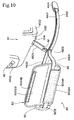
- the rear end of the inside belt section 4402 is attached in a detachable manner to the right side surface 1012 of the camera body 10. It is therefore possible to use the grip belt 40 as a strap belt by removing the rear end portion of the inside belt section 4402 from the right side surface 1012 of the camera body 10. In other words, as shown in FIG. 7 and FIG. 8, the inside belt section 4402 can be pulled away from the right side surface 1012 of the camera body 10 by detaching the clasp 4406 of the inside belt section 4402 of the grip belt 40 from the engaging/disengaging mechanism 46 of the camera body 10. Next, as shown in FIG. 9, FIG. 10 and FIG.
- the end of the joining section 4410 is extracted from between the pair of opening and closing flaps 5002A and 5002B, and the joining section 4410 is withdrawn until the engaging clasp 4414 engages with the belt connecting link 4202.
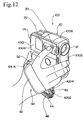
- the grip belt 40 can then be used as a strap belt by closing the pair of opening and closing clasps 5002A and 5002B via surface fasteners 5004A and 5004B. Specifically, when the joining section 4410 is pulled out until the engaging clasp 4414 engages with the belt connecting link 4202, as shown in FIG.
- the lengths of the inside belt section 4402 and the outside belt section 4404 become a maximum
- the size of the hand insertion section 48 also becomes a maximum
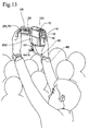
- the hand insertion section 48 becomes of a size capable of enabling the whole of the palm of a hand to enter within. It is therefore possible to insert the right hand through the hand insertion section 48 and use the grip belt 40 as a strap belt.
- the right hand is inserted through the hand insertion section 48 and the camera body 10 can be gripped using the right hand with the hand insertion section 48 positioned at the wrist.
- the grip belt 40 is constructed from the first belt 42 and the second belt 44 separate from the first belt 42.
- the grip belt 40 it is also possible for the grip belt 40 to be configured from a single belt depending on the handling condition of the belt and/or the structure of the belt connecting link 4202.
- the present invention can then naturally be applied to a configuration where the grip belt 40 is a single belt.
- the belt portion corresponding to this embodiment will correspond to the first belt 42 and the second belt 44 respectively.
- this embodiment shows an example where the camera is a video camera, but the present invention may also be naturally applied to various cameras such as digital cameras, television cameras or film-type cameras.
Landscapes
- Engineering & Computer Science (AREA)
- Multimedia (AREA)
- Signal Processing (AREA)
- Physics & Mathematics (AREA)
- General Physics & Mathematics (AREA)
- Studio Devices (AREA)
- Accessories Of Cameras (AREA)
- Camera Bodies And Camera Details Or Accessories (AREA)
Applications Claiming Priority (2)
| Application Number | Priority Date | Filing Date | Title |
|---|---|---|---|
| JP2003432261 | 2003-12-26 | ||
| JP2003432261A JP2005192011A (ja) | 2003-12-26 | 2003-12-26 | カメラ |
Publications (1)
| Publication Number | Publication Date |
|---|---|
| EP1547485A2 true EP1547485A2 (de) | 2005-06-29 |
Family
ID=34545058
Family Applications (1)
| Application Number | Title | Priority Date | Filing Date |
|---|---|---|---|
| EP04293132A Withdrawn EP1547485A2 (de) | 2003-12-26 | 2004-12-24 | Kamera mit Haltegurt |
Country Status (5)
| Country | Link |
|---|---|
| US (1) | US7192204B2 (de) |
| EP (1) | EP1547485A2 (de) |
| JP (1) | JP2005192011A (de) |
| KR (1) | KR20050067009A (de) |
| CN (1) | CN100336380C (de) |
Cited By (1)
| Publication number | Priority date | Publication date | Assignee | Title |
|---|---|---|---|---|
| US20050285964A1 (en) * | 2004-06-16 | 2005-12-29 | Kenichiro Imai | Image pickup apparatus having a display panel |
Families Citing this family (14)
| Publication number | Priority date | Publication date | Assignee | Title |
|---|---|---|---|---|
| KR20050090821A (ko) * | 2004-03-10 | 2005-09-14 | 삼성전자주식회사 | 영상촬영장치의 하우징 커버 |
| US7623155B2 (en) * | 2004-09-29 | 2009-11-24 | Kelliher Christopher R | GPS enhanced camera for transmitting real-time trail data over a satellite/cellular communication channel |
| US20060289768A1 (en) * | 2005-04-22 | 2006-12-28 | Frank Vallese | Portable infrared camera |
| US20070000958A1 (en) * | 2005-06-30 | 2007-01-04 | Jaeho Choi | Securing arrangement for a mobile device |
| US20070095304A1 (en) * | 2005-10-28 | 2007-05-03 | Maury Rosenberg | System for Monitoring the Environment of an Animal |
| JP4566967B2 (ja) * | 2005-12-16 | 2010-10-20 | キヤノン株式会社 | 画像記録再生装置 |
| EP1901548B1 (de) * | 2006-09-12 | 2013-07-31 | Samsung Electronics Co., Ltd. | Fotografiervorrichtung |
| CN200969975Y (zh) * | 2006-11-29 | 2007-11-07 | 顾欣 | 新型手垫 |
| KR20080061844A (ko) * | 2006-12-28 | 2008-07-03 | 삼성전자주식회사 | 영상촬영장치 |
| KR101475412B1 (ko) * | 2007-06-27 | 2014-12-22 | 삼성전자주식회사 | 그립장치 및 이를 포함하는 영상촬영장치 |
| US20090003820A1 (en) * | 2007-07-01 | 2009-01-01 | David Law | Strap for Cameras and Video Recorders |
| JP6112495B1 (ja) | 2016-02-19 | 2017-04-12 | パナソニックIpマネジメント株式会社 | 電子機器用ハンドストラップ |
| JP2018097188A (ja) * | 2016-12-14 | 2018-06-21 | 株式会社Jvcケンウッド | グリップベルト及び撮像装置 |
| JP6534109B1 (ja) * | 2018-12-25 | 2019-06-26 | パナソニックIpマネジメント株式会社 | ストラップ |
Citations (1)
| Publication number | Priority date | Publication date | Assignee | Title |
|---|---|---|---|---|
| JP2001053987A (ja) | 1999-08-10 | 2001-02-23 | Sony Corp | ビデオカメラ |
Family Cites Families (9)
| Publication number | Priority date | Publication date | Assignee | Title |
|---|---|---|---|---|
| KR910001707Y1 (ko) * | 1986-06-05 | 1991-03-18 | 니뽕 빅터 가부시끼가이샤 | 카메라 일체형 비디오 테이프 레코더 |
| US4819016A (en) * | 1988-03-16 | 1989-04-04 | Eastman Kodak Company | Photographic camera |
| JPH03198806A (ja) * | 1989-12-27 | 1991-08-30 | Canon Inc | カメラ |
| DE69229895T2 (de) * | 1991-06-18 | 2000-04-20 | Canon K.K. | Videokamera |
| US5341171A (en) * | 1991-08-23 | 1994-08-23 | Sony Corporation | Video camera apparatus with a connecting device for easy connection with electric apparatus |
| JP2656884B2 (ja) * | 1993-03-01 | 1997-09-24 | 富士写真フイルム株式会社 | カメラ一体型vtr |
| JPH07281265A (ja) * | 1994-04-14 | 1995-10-27 | Hitachi Ltd | 情報記録装置 |
| JP2003008961A (ja) * | 2001-06-25 | 2003-01-10 | Canon Inc | 安定保持機構を有する撮像装置 |
| JP2004214752A (ja) * | 2002-12-27 | 2004-07-29 | Hitachi Ltd | 撮影装置 |
-
2003
- 2003-12-26 JP JP2003432261A patent/JP2005192011A/ja not_active Abandoned
-
2004
- 2004-12-07 US US11/004,987 patent/US7192204B2/en not_active Expired - Fee Related
- 2004-12-10 CN CNB2004100866551A patent/CN100336380C/zh not_active Expired - Fee Related
- 2004-12-17 KR KR1020040108047A patent/KR20050067009A/ko not_active Withdrawn
- 2004-12-24 EP EP04293132A patent/EP1547485A2/de not_active Withdrawn
Patent Citations (1)
| Publication number | Priority date | Publication date | Assignee | Title |
|---|---|---|---|---|
| JP2001053987A (ja) | 1999-08-10 | 2001-02-23 | Sony Corp | ビデオカメラ |
Cited By (1)
| Publication number | Priority date | Publication date | Assignee | Title |
|---|---|---|---|---|
| US20050285964A1 (en) * | 2004-06-16 | 2005-12-29 | Kenichiro Imai | Image pickup apparatus having a display panel |
Also Published As
| Publication number | Publication date |
|---|---|
| JP2005192011A (ja) | 2005-07-14 |
| US20060204241A1 (en) | 2006-09-14 |
| CN100336380C (zh) | 2007-09-05 |
| CN1638431A (zh) | 2005-07-13 |
| KR20050067009A (ko) | 2005-06-30 |
| US7192204B2 (en) | 2007-03-20 |
Similar Documents
| Publication | Publication Date | Title |
|---|---|---|
| US7192204B2 (en) | Camera | |
| JP4384169B2 (ja) | ケース | |
| JP4380475B2 (ja) | 撮像装置 | |
| US8493507B2 (en) | Glare blocking camcorder/camera stabilizing eye level viewfinder device and method | |
| JP7114360B2 (ja) | 撮像装置 | |
| US6842193B2 (en) | Electronic camera | |
| US6942400B2 (en) | Image pickup apparatus with mechanism for stably holding image pickup apparatus | |
| JP2005189601A (ja) | カメラ | |
| JP2009045160A (ja) | 撮像装置用ケース | |
| US20110135272A1 (en) | Portable electronic apparatus equipped with recording function | |
| JP4687000B2 (ja) | 撮像装置用ケース | |
| JP2005249869A (ja) | 撮像装置用ケース | |
| JP2007033941A (ja) | 携帯用撮像機器、携帯用撮像機器用のハンドグリップ | |
| JPH07107377A (ja) | 画像入力装置 | |
| JPH0748094Y2 (ja) | カメラ用キャリングケース | |
| JP2004287334A (ja) | カメラ | |
| JP2561902Y2 (ja) | カメラ用ケース | |
| JP3038936U (ja) | カメラカバー | |
| JP4254254B2 (ja) | カメラジャケット | |
| JP3713928B2 (ja) | カメラ装置 | |
| JP4724471B2 (ja) | カメラ | |
| JP2000305132A (ja) | 撮像装置のレンズカバー収納機構 | |
| JP2015125314A (ja) | 撮像装置のグリップ | |
| JP2007105091A (ja) | カメラバッグ | |
| KR930008709Y1 (ko) | 뷰파인더 렌즈경통부 결합장치 |
Legal Events
| Date | Code | Title | Description |
|---|---|---|---|
| PUAI | Public reference made under article 153(3) epc to a published international application that has entered the european phase |
Free format text: ORIGINAL CODE: 0009012 |
|
| AK | Designated contracting states |
Kind code of ref document: A2 Designated state(s): AT BE BG CH CY CZ DE DK EE ES FI FR GB GR HU IE IS IT LI LT LU MC NL PL PT RO SE SI SK TR |
|
| AX | Request for extension of the european patent |
Extension state: AL BA HR LV MK YU |
|
| STAA | Information on the status of an ep patent application or granted ep patent |
Free format text: STATUS: THE APPLICATION IS DEEMED TO BE WITHDRAWN |
|
| 18D | Application deemed to be withdrawn |
Effective date: 20080701 |