EP1545970B9 - Wasserstrahlantrieb für wasserfahrzeuge - Google Patents
Wasserstrahlantrieb für wasserfahrzeuge Download PDFInfo
- Publication number
- EP1545970B9 EP1545970B9 EP02785156A EP02785156A EP1545970B9 EP 1545970 B9 EP1545970 B9 EP 1545970B9 EP 02785156 A EP02785156 A EP 02785156A EP 02785156 A EP02785156 A EP 02785156A EP 1545970 B9 EP1545970 B9 EP 1545970B9
- Authority
- EP
- European Patent Office
- Prior art keywords
- propeller
- pump
- hydrojet
- housing
- drive
- Prior art date
- Legal status (The legal status is an assumption and is not a legal conclusion. Google has not performed a legal analysis and makes no representation as to the accuracy of the status listed.)
- Expired - Lifetime
Links
Images


Classifications
-
- B—PERFORMING OPERATIONS; TRANSPORTING
- B63—SHIPS OR OTHER WATERBORNE VESSELS; RELATED EQUIPMENT
- B63H—MARINE PROPULSION OR STEERING
- B63H11/00—Marine propulsion by water jets
- B63H11/02—Marine propulsion by water jets the propulsive medium being ambient water
- B63H11/10—Marine propulsion by water jets the propulsive medium being ambient water having means for deflecting jet or influencing cross-section thereof
- B63H11/101—Marine propulsion by water jets the propulsive medium being ambient water having means for deflecting jet or influencing cross-section thereof having means for deflecting jet into a propulsive direction substantially parallel to the plane of the pump outlet opening
- B63H11/102—Marine propulsion by water jets the propulsive medium being ambient water having means for deflecting jet or influencing cross-section thereof having means for deflecting jet into a propulsive direction substantially parallel to the plane of the pump outlet opening the inlet opening and the outlet opening of the pump being substantially coplanar
-
- B—PERFORMING OPERATIONS; TRANSPORTING
- B63—SHIPS OR OTHER WATERBORNE VESSELS; RELATED EQUIPMENT
- B63H—MARINE PROPULSION OR STEERING
- B63H11/00—Marine propulsion by water jets
- B63H11/02—Marine propulsion by water jets the propulsive medium being ambient water
- B63H11/04—Marine propulsion by water jets the propulsive medium being ambient water by means of pumps
- B63H11/08—Marine propulsion by water jets the propulsive medium being ambient water by means of pumps of rotary type
-
- B—PERFORMING OPERATIONS; TRANSPORTING
- B63—SHIPS OR OTHER WATERBORNE VESSELS; RELATED EQUIPMENT
- B63H—MARINE PROPULSION OR STEERING
- B63H11/00—Marine propulsion by water jets
- B63H11/02—Marine propulsion by water jets the propulsive medium being ambient water
- B63H11/10—Marine propulsion by water jets the propulsive medium being ambient water having means for deflecting jet or influencing cross-section thereof
- B63H11/107—Direction control of propulsive fluid
Definitions
- the invention relates to a water jet drive for watercraft.
- waterjet propulsion systems which are preferably arranged on the bow side in the ground area have proved to be suitable for improving the maneuverability.
- Such water jet drives also referred to as bow jet systems, comprise a housing which can be installed in the respective vehicle floor and contains at least one propeller (or a pump impeller) which supplies energy to the water supplied via a bottom housing inlet and, for example, via a manifold and channels in the latter Direction radiates, or by at least one floor level and usually 360 ° swiveling outlet under the ship's bottom controls all around.
- the axis of rotation of the propeller or the pump impeller extends either in the horizontal or vertical direction.
- Water jet drives with vertically oriented axis of rotation need for the above a bottom inlet horizontally arranged propeller (or pump impeller) Although a relatively small draft for air-free work, but have the disadvantage, inter alia, that such drives at low water depth (ie at less than, for example, about 50 cm Water under the keel) create a strong suction due to their directly directed to the bottom suction, which increases the ship's resistance and affects the shear development or completely collapse, if increasingly sucked foreign bodies enforce the usually existing protective grid.
- a water jet drive for bow control for ships is known in which a propeller is provided, whose axis relative to a horizontal base has an inclination angle ⁇ 45 °.
- ⁇ 45 ° As in the case of the above EP 0 024 443 A is the outlet for the water jet in the direction of travel in front of the inlet opening.
- the invention is based on the object to provide a simple and inexpensive to produce water jet propulsion pump with a propeller for watercraft, especially for displacement vehicles, which generates an optimized thrust with optimized flow during maneuvering and increasing speed and has better shallow water properties than the known bow jet - Systems and - with alternative engines - as a compact drive unit in the bottom of a watercraft welded (or lamination) leaves.
- the invention is based essentially on the idea, on the one hand to arrange the propeller shaft of the water jet drive on the pressure side of the respective propeller pump in such a commercial 90 ° - pipe bend that the propeller axis is not vertical or horizontal, but at an inclination angle ⁇ of 20 ° to 50 °, Preferably between 25 ° and 40 ° - relative to the bottom plate as a horizontal base and at the other obliquely downwardly facing end of the pipe bend add an outlet housing section and provided with a rotatable Bodenumlenkgitter to the exit jet and thus the propeller thrust under the bottom of the Water jet drive all around in all directions to control.
- the water jet drive is designed such that an inlet - housing section is provided, which is aligned with the intended use of the water jet drive in the main direction of travel, wherein the bottom-side inlet opening of the housing unit is arranged in front of the outlet opening.
- the water jet drive consists of an insertable into the ship's bottom housing unit, which is formed from at least four interconnected housing sections: a preferably designed for displacement vehicles flush floor inlet - housing section, concentrically connected to a tubular pump housing section with an axis inclined to the horizontal. At the other end of this pump housing section an arcuate housing section is attached at the same inclination, which serves as a housing base with an integrated propeller shaft bearing and which is preferably formed by a commercially available 90 ° round arch, but can also be designed in any other way. At the other obliquely downward-pointing end of the arc a floor-mounted outlet housing section is added, in which there is a storage of a controllable Bodenumlenkgitters.
- the inlet housing section is designed according to special shape and cross-sectional features, the different flow conditions (as in the suction - and supply operation in stationary pumps in a similar manner) best meet.
- the inlet - housing contour above the inlet opening assumes a trapezoidal cross-section with rounded corners until the corner radii form a curved cross-section with a circular radius, to which a conical pump inlet nozzle attaches.
- this inlet - housing section By aligning the contours of this inlet - housing section in the main direction of travel (ie straight ahead) and at the same time also lateral or oblique inflows be detected funnel-like, the water is optimally supplied to the propeller inclined to the flow.
- the tubular pump housing section which is arranged between the inlet housing section and the pipe bend and which consists of a particularly corrosion - resistant. wear-resistant material is provided forms a centric pump housing with at least one propeller and behind fixed stator blades, which convert the spin energy into flow energy and at the same time serve as webs to support the central bearing hub, a propeller pump.
- An alternative support of the bearing hub e.g. with spokes of round cross section, etc. is also conceivable and included.
- the waterjet propulsion system is to be driven by an internal combustion engine
- V version with a standard axial inclination angle of, for example, 10 °.
- the engine and transmission can be aligned with each other on a common base frame and fixed, which in turn is then based as an elastically mounted unit mounted on the water jet propulsion consoles.
- the turning stage of this marine gearbox can be used for flushing the inlet protection grille.
- the inlet housing section can be designed in special installation-specific variants. For example, by making the entry level of the leading or a lateral leading edge a little higher u./od. By varying the inclination of the front or side casing surface, flat open areas can be created in the bow area or on the side of a watercraft so that additional (air-free) water can flow directly to the propeller from the front or from the side. (For example, in pontoon or double end ferries with lateral or diagonal jet installation.)
- the waterjet propulsion system according to the invention can be used for different types of vessels and for different purposes, e.g. as a maneuvering u.
- vehicle types are mainly inland vessels, such as cargo, passenger and work ships and ferries, landing craft, government vehicles and those with increased requirements for holding positions such. Fire-fighting boats, diver ships, measuring u. Laboratory vessels etc. into consideration.
- the water jet drive according to the invention can also with appropriate design as a maneuvering in coastal u. Oceangoing ships are used.
- an inventive water jet drive is referred to, driven either via a coaxially mounted electric motor 2 (in flange) or an axially parallel mounted electric motor 2 '(foot version) by means of belt drive 38 and corresponding reduction with the desired propeller speed or peripheral speed can be.
- the water jet propulsion system 1 consists of a housing unit 3 which can be inserted into the ship bottom (not shown) and consists of four housing sections 4 - 7 connected to one another: a floor - mounted inlet housing section 4 preferably designed for positive displacement vehicles, to which a tubular pump housing section 5 concentrically surrounds Recording a propeller 10 connects.
- the propeller rotation axis 9 and thus also the propeller shaft 11 are arranged at an angle of inclination ⁇ of preferably 28 ° with respect to a horizontal base formed by the base plate 20 of the housing unit 3.
- a pipe bend 6 is added to the pump - housing section 5, which serves to support the propeller shaft 11 as a housing base and which may be a commercially available 90 ° - round arch.
- a floor-mounted outlet housing section 7 with an outlet opening 15 is added, in which a pivotable Bodenumlenkgitter 16 is arranged to control the water jet.
- control shaft 17 and the propeller shaft 11 concentric bearing stub 18, 19 are arranged on the round arch 6 to the respective shaft axes.
- the water-conducting housing sections 4 - 7 and a bottom plate 20 connecting the inlet and outlet openings 13 and 15 are interconnected to form a pre-producible housing unit 3, which is provided with corresponding motor consoles 37 or foundation brackets 45, 46 for installation of the desired drive motor 2, 2 'and 40 can be completed.
- housing unit 3 with an inspection cover on the idle water line (not shown) executable that allows inspection from the engine room and cleaning the inlet area.
- the water is optimally supplied to the propeller 10, which is inclined towards the flow.
- the FIG. 3 u. 4 obliquely outwardly issued side surfaces of the inlet housing section 4 are also detected with funnel-like effect oblique or lateral flows.
- the contours of the inlet housing section 4 are selected such that the profiles of the tunnel cross sections 21, 22 in Fig. 3 u. 4 with respect to their height and their upper corner radii steadily increase until they form a tunnel with a circular curvature, to which a conical pump inlet nozzle 23 attaches. Below the propeller axis of rotation 9, the contour of the pump inlet nozzle 23 decreases until it merges into the bottom plate 20 downwards.
- Alternative versions are conceivable and included.
- a protective grid 24 against foreign bodies of detrimental size which either fixed - or shaking evt.
- Foreign body - is pivotally mounted and disassembly easy accessibility of the inlet region and the propeller 10 for inspection , Maintenance and repair possible.
- the tubular pump housing section 5 arranged between the inlet housing section 4 and the pipe bend 6 forms, with a narrow radial gap around at least one propeller 10, the pump housing and, together with the guide vanes 26 arranged behind it, which convert the swirl energy into flow energy and at the same time support the bearing hub 27 Serve, the propeller pump 8.
- an alternative hub support for example, with unprofiled spokes (instead of 26) conceivable and included.
- the propeller side Bearing hub 27 preferably includes a conventional water lubricated propeller shaft sleeve bearing 39.
- the upper double-sealed propeller shaft bearing 28 is provided as a grease-lubricated roller bearing for receiving axial and radial loads and arranged in the attached to the pipe bend 6 bearing stub 19.
- a bearing hub 30 which is supported via webs 29 is likewise arranged for receiving and supporting the floor deflection grille, wherein at least two webs 29 are arranged above the front floor half in such a way that they favor the flow guidance on or through the floor deflection grille 16.
- the vertical control shaft 17 below preferably in a water-lubricated plain bearing 31 and above in a sealed on both sides and greased roller bearing 32, which can accommodate axial and radial loads stored in the bearing stub 18 of the housing unit 3.
- a drive hub 33 for the (not shown) control drive and a small output hub 34 for the (not shown) optical u. elec. Thrust direction indicator arranged.
- the electric motor 2 (in flange design) is connected via an elastic shaft coupling 35 with the propeller shaft 11 and mounted via a coaxial bell housing 36 on the bearing neck 19 of the housing unit 3.
- the use of an electric motor 2 '(in complicataus Entry) and a corresponding high-performance belt drive 38 for driving the propeller shaft 11 allow the adaptation of frequency-dependent engine speeds to a single propeller speed or to a certain peripheral speed.
- the electric motors 2, 2 ' can be installed either in front of the propeller shaft 11 or by means of an axially parallel motor bracket 37 above or laterally on the housing unit 3 of the water jet drive 1 ready for use drive unit.
- an internal combustion engine 40 for driving the water jet drive 1 is provided.
- the internal combustion engine 40 with the torsionally flexible engine clutch 41 attached thereto is together with a commercial marine gearbox 42, preferably in a V version (ie, the horizontal drive and the inclined output axles form one "Lying V") mounted on a common base frame 43 and positioned so that the connecting propeller shaft 44 results in a W - arrangement with two equal diffraction angles in a permissible size.
- the base frame 43 is aligned on foundation brackets 45, 46, which are arranged on the housing unit 3, at least four points via rubber - metal - damping elements 47 to the propeller shaft 11 and elastically mounted. Load-dependent displacements or deflections are compensated by the elastic shaft coupling 48 in double cardan design.
- the rubber-metal damping elements 47 and the two elastic elements of the coupling 48 simultaneously serve to effectively dampen the transmission of vibrations and structure-borne noise to the water-jet drive 1 and thus to the hull.
- the invention is not limited to the embodiment described above.
- the water-jet drive can in principle also be designed with a two-stage propeller pump (pump with a propeller shaft 11 and two propellers 10 with guide vanes 26 therebetween).
- the water jet drive 1 can in principle also be realized with a variable pitch propeller pump, in which case the propeller shaft 11 is hollow drilled in order, for example, to guide an actuating rod or lines for adjusting the propeller blades (or the propeller pitch).
- the device for pitch adjustment in front of the bearing neck 19 on the water jet drive 1 can be mounted.
- an extended actuating rod through the shaft coupling 48 and the hollow-drilled output shaft of the marine gear 42 can be passed, so that the adjustment - as usual - outside the marine gearbox 42 is attachable.
Landscapes
- Chemical & Material Sciences (AREA)
- Engineering & Computer Science (AREA)
- Combustion & Propulsion (AREA)
- Mechanical Engineering (AREA)
- Ocean & Marine Engineering (AREA)
- Structures Of Non-Positive Displacement Pumps (AREA)
- Hydraulic Turbines (AREA)
- Separation Using Semi-Permeable Membranes (AREA)
- Fittings On The Vehicle Exterior For Carrying Loads, And Devices For Holding Or Mounting Articles (AREA)
- Water Treatment By Electricity Or Magnetism (AREA)
- Agricultural Chemicals And Associated Chemicals (AREA)
Description
- Die Erfindung betrifft einen Wasserstrahlantrieb für Wasserfahrzeuge.
- Insbesondere bei Wasserfahrzeugen, die auch im Flachwasser (z.B. auf Binnengewässern mit variierenden Pegelständen) eingesetzt werden, haben sich zur Verbesserung der Manöverierfähigkeit Wasserstrahlantriebe bewährt, die vorzugsweise bugseitig im Bodenbereich angeordnet werden. Derartige auch als Bug Jet - Anlagen bezeichnete Wasserstrahlantriebe umfassen ein in den jeweiligen Fahrzeugboden einbaubares Gehäuse, welches mindestens einen Propeller (bzw. ein Pumpenlaufrad) enthält, der das über einen bodenseitigen Gehäuseeinlauf zugeführte Wasser mit Energie beaufschlagt und beispielsweise über einen Krümmer und Kanäle in deren Richtung abstrahlt, oder durch mindestens eine bodenbündige und i.d.R. um 360° verschwenkbare Austrittsöffnung unter dem Schiffsboden rundum steuert.
- Bei bekannten Wasserstrahlantrieben erstreckt sich die Drehachse des Propellers bzw. des Pumpenlaufrades entweder in horizontaler oder vertikaler Richtung.
- Bei einer vertikalen Propelleranordnung d.h. bei Drehung um eine horizontale Querachse in einem Querstrahltunnel ist zu beachten, dass zur Vermeidung von Lufteinbrüchen und dem dadurch verursachten Schubabfall die Wasserlinie etwa um einen halben Propellerdurchmesser über dem Tunnelscheitel liegen sollte. Dadurch ergibt sich der Nachteil, dass das betreffende Wasserfahrzeug einen relativ großen Tiefgang aufweist und eine entsprechende Fahrwassertiefe benötigt, um es risikofrei und effizient manöverieren zu können.
- Neben diesen sind auch Wasserstrahlantriebe mit vertikaler Propelleranordnung bekannt, die zur Reduzierung des Tiefgangs nach dem Prinzip üblicher Axial Jets über einen Bodeneinlauf verfügen. Weil das Ansaugverhalten axialer Propellerpumpen nur eine begrenzte Austauchung der Propellerschaufeln zuläßt, ist ein funktionsbedingtes Tiefgangsverhältnis sicherzustellen.
- Aus der
EP 0 024 443 A ist ein Wasserstrahlantrieb zur Bugsteuerung eines Wasserfahrzeuges mit horizontal ausgerichteter Propellerdrehachse bekannt. Bei diesem bekannten Wasserstrahlantrieb befindet sich die Austrittsöffnung für den Wasserstrahl in Fahrtrichtung vor der Eintrittsöffnung, so daß lediglich ein Bremsschuh und zur Unterstützung der heckseitigen Ruderanlage ein Manövrierschub erzeugt werden kann. Hingegen läßt sich mit einem derart konstruierten und im Schiffsbug angeordneten Wasserstrahlantrieb kein wirtschaftlicher Fahrschub erzeugen, weil ein Vortrieb erzeugender und insofern relativ flach geneigter Schubstrahl in der Geradeausfahrt die dort steil nach oben gerichtete Ansaugströmung kreuzt bsw. stark verwirbelt. Die dabei erzeugten Turbulenzen und Sogwirkungen erhöhen die Einlaufverluste stark und mindern somit die Schubentwicklung in dieser Steuerzone drastisch. Das hierbei mitangesaugte Propellerwasser trägt ebenfalls zur Schubminderung bei, weil es bei höherer Eintrittsgeschwindigkeit weniger beschleunigt wird und somit weniger Schub erbringt. - Wasserstrahlantriebe mit vertikal ausgerichteter Drehachse benötigen für den über einem Bodeneinlauf horizontal angeordneten Propeller (bzw. Pumpenlaufrad) zwar einen relativ geringen Tiefgang zum luftfreien Arbeiten, weisen aber u.a. den Nachteil auf, dass derartige Antriebe bei geringer Wassertiefe (d.h. bei weniger als z.B. etwa 50 cm Wasser unter dem Kiel) durch ihre unmittelbar auf den Grund gerichtete Saugwirkung einen starken Sog erzeugen, welcher den Schiffswiderstand erhöht und die Schubentwicklung beeinträchtigt bzw. ganz zusammenbrechen lässt, wenn verstärkt angesaugte Fremdkörper das üblicherweise vorhandene Schutzgitter zusetzen.
- Ferner steigt dabei das Beschädigungsrisiko an, weil kleine Fremdkörper das Schutzgitter wie ein Sieb passieren und vermehrt in bzw. zwischen die Beschaufelung gelangen können.
- Außerdem hat sich gezeigt, dass bei Wasserstrahlantrieben mit vertikal ausgerichteter Propellerdrehachse bei zunehmender Fahrt die in den vertikalen Ansaugbereich umzulenkende Strömung ab einer bestimmten Fahrtgeschwindigkeit abzureißen beginnt, was dann einen drastischen Schubabfall zur Folge hat.
- Zum Antrieb über einen horizontal angeordneten Motor benötigen Wasserstrahlantriebe mit vertikaler Propellerdrehachse ein eigenes Winkelgetriebe. Und zum Antrieb über Verbrennungsmotore ist zum Kuppeln und Umschalten der Drehrichtung (beispielsweise zum Spülen des Schutzgitters) noch ein Schiffswendegetriebe erforderlich, das als zweites Getriebe die mechanischen Verluste und die Kosten der Anlage erhöht.
- Aus der
CH 551 311 A EP 0 024 443 A befindet sich die Austrittsöffnung für den Wasserstrahl in Fahrtrichtung vor der Eintrittsöffnung. Die dort hinter dem Propeller angeordneten selbstschließenden Lamellen sowie die nur in einer Strahlrichtung effiziente Ruderwirkung schließen eine Nutzung dieses Antriebs zur Fahrtschuberzeugung aus. - Schließlich ist aus der
US 3,263,643 ein Luftkissenfahrzeug bekannt, welches sowohl heckwie bugseitig über Jetantriebe verfügt. Bei beiden Antrieben befindet sich die jeweilige Propellerwelle auf der Saugseite des entsprechenden Propellers, so daß es beim Betrieb dieser Antriebe zu starken Wirbelbildungen des jeweiligen Wasserstromes kommt, welcher der kavitationsempfindlichen Propeller-Saugseite zugeführt wird. Dadurch wird nicht nur die Gefahr einer Beschädigung der Propeller durch Kavitation erhöht, sondern auch der Wirkungsgrad derartiger Antriebe ist nicht optimal. Außerdem sind mit dem Betrieb derartiger Antriebe relativ hohe Vibrationen verbunden. - Der Erfindung liegt die Aufgabe zu Grunde, einen möglichst einfachen und kostengünstig herstellbaren Wasserstrahlantrieb mit einer Propellerpumpe für Wasserfahrzeuge, insbesondere für Verdrängerfahrzeuge, anzugeben, der mit optimierter Anströmung beim Manöverieren und bei zunehmender Fahrt einen effizienten Schub erzeugt und bessere Flachwassereigenschaften aufweist als die bekannten Bug Jet - Anlagen und sich - mit alternativen Motoren - als kompaktes Antriebsaggregat in den Boden eines Wasserfahrzeuges einschweißen (oder einlaminieren) lässt.
- Diese Aufgabe wird erfindungsgemäß durch die Merkmale des Anspruchs 1 gelöst. Weitere, besonders vorteilfhafte Ausgestaltung der Erfindung offenbaren die Unteransprüche.
- Die Erfindung beruht im wesentlichen auf dem Gedanken, einerseits die Propellerwelle des Wasserstrahlantriebes auf der Druckseite der jeweiligen Propellerpumpe derart in einem handelsüblichen 90°- Rohrbogen anzuordnen, dass die Propellerdrehachse nicht senkrecht oder waagerecht, sondern unter einem Neigungswinkel α von 20° bis 50°, -vorzugsweise zwischen 25° und 40°- gegenüber der Bodenplatte als horizontale Basis aufweist und am anderen schräg nach unten weisenden Ende des Rohrbogens eine Austritts-Gehäusesektion anzufügen und mit einem drehbaren Bodenumlenkgitter zu versehen, um den Austrittsstrahl und somit den Propellerschub unter dem Boden des Wasserstrahlantriebs rundum in alle Richtungen zu steuern. Andererseits ist der Wasserstrahlantrieb derart ausgebildet, daß eine Einlauf - Gehäusesektion vorgesehen ist, die bei der bestimmungsgemäßen Verwendung des Wasserstrahlantriebes auf die hauptsächliche Fahrtrichtung ausgerichtet ist, wobei die bodenseitige Eintrittsöffnung der Gehäuseeinheit vor der Austrittsöffnung angeordnet ist.
- Durch diese Maßnahme werden gravierende Vorteile hinsichtlich :
- des konstruktiven Aufbaues und der Herstellung
- der Strömungsführung u. Schubentwicklung
- der Fahrtgeschwindigkeit u. des Tiefganges
- der Installation alternativer Antriebsmotore
- der Einbaumöglichkeiten in den Fahrzeugtypen
- Durch den auf die primäre Anströmrichtung zugeneigten Propeller und die konische Pumpeneinlaufdüse, die (gegenüber runden Einlaufdüsen) im oberen Ansaugbereich schädliche Luftansammlungen vermeidet, wird das Ansaugverhalten bei teilweise austauchenden Propellerschaufeln positiv beeinflusst. Gegenüber Wasserstrahlantrieben mit waagerechter Propellerdrehachse wird der erforderliche Tiefgang deutlich unterschritten.
- Indem die Saugwirkung des relativ flach geneigten Propellers nicht unmittelbar auf den Grund gerichtet ist und die Eintrittsöffnung (in Relation zum Propellerdurchmesser anderer Wasserstrahlantriebe) größer ist, werden die Flachwassereigenschaften bzgl. Schubentwicklung, Sogwirkung und Widerstand verbessert.
- Um einen besonders kompakten Aufbau des erfindungsgemäßen Wasserstrahlantriebes zu erzielen, hat es sich als vorteilhaft erwiesen, wenn der Wasserstrahlantrieb aus einer in den Schiffsboden einfügbaren Gehäuseeinheit besteht, die aus mindestens vier miteinander verbundenen Gehäusesektionen gebildet wird: einer vorzugsweise für Verdrängerfahrzeuge konzipierten bodenbündigen Einlauf - Gehäusesektion, an die sich konzentrisch eine rohrförmige Pumpen - Gehäusesektion mit einer zur Horizontalen geneigten Achse anschließt. Am anderen Ende dieser Pumpen - Gehäusesektion ist unter gleicher Neigung eine bogenförmige Gehäusesektion angefügt, die mit einer integrierten Propellerwellen - Lagerung als Gehäusebasis dient und die vorzugsweise durch einen handelsüblichen 90° - Rundbogen gebildet wird, aber auch in sonstiger Weise gestaltet sein kann. Am anderen schräg nach unten weisenden Bogenende ist eine bodenbündige Austritts- Gehäusesektion angefügt, in der sich eine Lagerung eines steuerbaren Bodenumlenkgitters befindet.
- Zur optimalen Anströmung des Propellers als Voraussetzung einer effizienten Schubentwicklung zum Manöverieren im Stand bzw. bei niedriger Fahrtgeschwindigkeit, aber auch zum Fahren bis auf Marschgeschwindigkeit ist die Einlauf - Gehäusesektion nach speziellen Form- und Querschnittsmerkmalen gestaltet, die den unterschiedlichen Anströmverhältnissen (wie sie sich im Saug- und Zulaufbetrieb bei stationären Pumpen in ähnlicher Weise unterscheiden) am besten gerecht werden.
- Flach anlaufend nimmt die Einlauf - Gehäusekontur über der Einlauföffnung einen trapezähnlichen Querschnitt mit abgerundeten Ecken an, bis die Eckradien im weiter ansteigenden Verlauf einen gewölbten Querschnitt mit einem Kreisradius bilden, an den sich eine konische Pumpeneinlaufdüse anfügt.
- Indem die Konturen dieser Einlauf - Gehäusesektion auf die hauptsächliche Fahrtrichtung (d.h. in Geradeausfahrt) ausgerichtet sind und zugleich auch seitliche bzw. schräge Zuströmungen trichterähnlich erfasst werden, wird dem der Strömung zugeneigten Propeller das Wasser optimal zugeführt.
- Die zwischen Einlauf - Gehäusesektion und dem Rohrbogen angeordnete rohrförmige Pumpen - Gehäusesektion, die aus einem besonders korrosions- u. verschleißfesten Werkstoff vorgesehen ist, bildet als zentrisches Pumpengehäuse mit mindestens einem Propeller und dahinter fest angeordneten Statorschaufeln, welche die Drallenergie in Strömungsenergie umwandeln und zugleich als Stege zur Abstützung der zentrischen Lagernabe dienen, eine Propellerpumpe. Eine alternative Abstützung der Lagernabe z.B. mit Speichen runden Querschnitts etc. ist ebenso denkbar und eingeschlossen.
- Je nach den Gegebenheiten der Wasserfahrzeuge und der benötigten Antriebsleistung werden hauptsächlich Elektro- u. Verbrennungsmotore aber auch Hydraulikmotore zum Antrieb verwendet. Bei Verwendung von Elektromotoren werden je nach Bordfrequenz (z.B. 50 od. 60Hz) und Motorbauart (Polpaarzahl) unterschiedliche Antriebsdrehzahlen vorgegeben. Daher hat es sich als vorteilhaft erwiesen, wenn der Elektromotor entweder mittels einer koaxialen Gehäuseglocke direkt anbaubar oder achsparallel und mittels Hochleistungsriementrieb und entsprechend wählbarer Untersetzung über dem Wasserstrahlantrieb oder auch an der rechten bzw. linken Seite an der Gehäuseeinheit anbaubar ist.
- Wenn der Wasserstrahlantrieb über einen Verbrennungsmotor angetrieben werden soll, hat es sich als besonders zweckmäßig erwiesen, den Verbrennungsmotor über ein Schiffsgetriebe in sog. V - Version mit einem standardmäßig verfügbaren Achsneigungswinkel von z.B. 10° mit der Propellerwelle zu verbinden. Dadurch ist eine besonders kompakte Installation des Verbrennungsmotors an dem Wasserstrahlantrieb möglich. Vorzugsweise können Motor und Getriebe auf einem gemeinsamen Grundrahmen zueinander ausgerichtet und fest angeordnet sein, der dann seinerseits als elastisch gelagerte Einheit auf den am Wasserstrahlantrieb angebrachten Konsolen fundamentiert ist. Neben den standardmäßigen Untersetzungsvarianten zur Drehzahlanpassung ist die Wendstufe dieser Schiffsgetriebe zur spülenden Reinigung des Einlaufschutzgitters nutzbar.
- Um im überwiegenden Flachwassereinsatz einen effizienten Schub zu erreichen, ist die Einlauf- Gehäusesektion in speziellen einbauspezifischen Varianten ausführbar. Indem beispielsweise das Eintrittsniveau der vorderen bzw. einer seitlichen Eintrittskante etwas höher ausgeführt u./od. indem die Neigung der vorderen oder einer seitlichen Gehäusefläche variiert wird, lassen sich im Bugbereich oder an der Seite eines Wasserfahrzeuges flache offene Bereiche schaffen, so dass dem Propeller zusätzliches (luftfreies) Wasser direkt von vorne oder von der Seite zuströmen kann. (U.a. beispielsweise bei Ponton- bzw. Doppelendfähren mit seitlicher bzw. diagonaler Jet - Installation.)
- Im übrigen kann der erfindungsgemäße Wasserstrahlantrieb für unterschiedliche Typen von Wasserfahrzeugen und für unterschiedliche Zwecke, z.B. als Manöverier- u. Hilfsanlage und / oder als Hauptantriebsanlage an verschiedenen Positionen im Fahrzeugboden verwendet werden. Als Fahrzeugtypen kommen hauptsächlich Binnenschiffe, wie Fracht-, Personen- und Arbeitsschiffe sowie Fähren, Landungsfahrzeuge, Behördenfahrzeuge und solche mit erhöhten Anforderungen an das Halten von Positionen, wie z.B. Feuerlöschboote, Taucherschiffe, Meß- u. Laborschiffe etc. in Betracht. Der erfindungsgemäße Wasserstrahlantrieb kann aber auch bei entsprechender Auslegung als Manöverieranlage in Küsten- u. Hochseeschiffen zum Einsatz kommen.
- Weitere Einzelheiten und Vorteile der Erfindung ergeben sich aus den folgenden anhand von Figuren erläuterten Ausführungsbeispielen. Es zeigen:
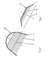
- Fig.1 den Längsschnitt eines erfindungsgemäßen Wasserstrahlantriebes mit einem Elektromotor als koaxialer Direktantrieb oder in achsparalleler Anordnung mit einem Riementrieb;
- Fig.2 eine Bodenansicht des in Fig. 1 dargestellten Wasserstrahlantriebes aus der in Fig. 1 mit II bezeichneten Richtung;
- Fig. 3 und 4 zwei Schnitte entlang der in Fig.2 mit III - III und IV - IV bezeichneten Schnittlinien;
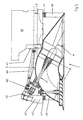
- Fig.5 den Längsschnitt des in Fig.1 dargestellten Wasserstrahlantriebs mit einem Verbrennungsmotor als Antrieb.
- In Fig.1 ist mit 1 ein erfindungsgemäßer Wasserstrahlantrieb bezeichnet, der entweder über einen koaxial angebauten Elektromotor 2 (in Flanschausführung) oder über einen achsparallel angebauten Elektromotor 2' ( in Fußausführung) mittels Riementrieb 38 und entsprechender Untersetzung mit der gewünschten Propellerdrehzahl bzw. Umfangsgeschwindigkeit angetrieben werden kann.
- Der Wasserstrahlantrieb 1 besteht aus einer in den Schiffsboden (nicht dargestellt) einfügbaren Gehäuseeinheit 3, die aus vier miteinander verbundenen Gehäusesektionen 4 - 7 besteht: einer vorzugsweise für Verdrängerfahrzeuge konzipierten bodenbündigen Einlauf - Gehäusesektion 4, an die sich konzentrisch eine rohrförmige Pumpen - Gehäusesektion 5 zur Aufnahme eines Propellers 10 anschließt. Erfindungsgemäß ist die Propellerdrehachse 9 und damit auch die Propellerwelle 11 unter einem Neigungswinkel α von vorzugsweise 28° gegenüber einer horizontalen Basis, die von der Bodenplatte 20 der Gehäuseeinheit 3 gebildet wird, angeordnet.
- In Richtung der geneigten Propellerdrehachse 9 ist an die Pumpen - Gehäusesektion 5 ein Rohrbogen 6 angefügt, der zur Lagerung der Propellerwelle 11 als Gehäusebasis dient und bei dem es sich um einen handelsüblichen 90°- Rundbogen handeln kann. Am anderen schräg nach unten weisenden Bogenende 14 des Rohrbogens 6 ist eine bodenbündige Austritts- Gehäusesektion 7 mit einer Austrittsöffnung 15 angefügt, in der ein verschwenkbares Bodenumlenkgitter 16 zur Steuerung des Wasserstrahles angeordnet ist.
- Zur Durchführung, Lagerung und Abdichtung der Steuerwelle 17 und der Propellerwelle 11 sind auf dem Rundbogen 6 zu den jeweiligen Wellenachsen konzentrische Lagerstutzen 18, 19 angeordnet.
- Die wasserführenden Gehäusesektionen 4 - 7 und eine die Eintritts- und Austrittsöffnungen 13 und 15 verbindende Bodenplatte 20 sind untereinander zu einer vorproduzierbaren Gehäuseeinheit 3 verbunden, die mit entsprechenden Motorkonsolen 37 bzw. Fundamentkonsolen 45, 46 zur Installation des gewünschten Antriebsmotors 2, 2' bzw. 40 komplettierbar ist.
- Ferner ist die Gehäuseeinheit 3 mit einem Inspektionsdeckel über der Leerwasserlinie (nicht dargestellt) ausführbar, der vom Maschinenraum aus eine Inspektion und Reinigung des Einlaufbereiches ermöglicht.
- Indem die Konturen der Einlauf- Gehäusesektion 4 auf die hauptsächliche Fahrtrichtung (d.h. in Geradeausfahrt) ausgerichtet sind, wird dem der Strömung zugeneigten Propeller 10 das Wasser optimal zugeführt. Über die gemäß Fig. 3 u. 4 schräg nach außen ausgestellten Seitenflächen der Einlauf- Gehäusesektion 4 werden mit trichterähnlicher Wirkung auch schräge bzw. seitliche Anströmungen erfasst.
- Dabei sind die Konturen der Einlauf- Gehäusesektion 4 derart gewählt, dass sich die Profile der Tunnelquerschnitte 21, 22 in Fig. 3 u. 4 bzgl. ihrer Höhe und ihrer oberen Eckradien stetig vergrößern bis sie einen Tunnel mit kreisförmiger Wölbung bilden, an den sich eine konische Pumpeneinlaufdüse 23 anfügt. Unterhalb der Propellerdrehachse 9 nimmt die Kontur der Pumpeneinlaufdüse 23 ab, bis sie nach unten hin in die Bodenplatte 20 übergeht. Alternative Ausführungen dazu sind denkbar und eingeschlossen.
- Im Bereich der Eintrittsöffnung 13 der Einlauf- Gehäusesektion 4 befindet sich ein Schutzgitter 24 gegen Fremdkörper in schädlicher Größe, welches entweder fest montiert - oder zum Abschütteln evt. Fremdkörper - schwenkbar angeordnet ist und bei Demontage eine einfache Zugänglichkeit des Einlaufbereiches und des Propellers 10 zur Inspektion, Wartung und im Reparaturfall ermöglicht.
- Die zwischen Einlauf- Gehäusesektion 4 und dem Rohrbogen 6 angeordnete rohrförmige Pumpen- Gehäusesektion 5 bildet mit einem engen Radialspalt um mindestens einen Propeller 10 das Pumpengehäuse und zusammen mit den dahinter angeordneten Leitschaufeln 26, welche die Drallenergie in Strömungsenergie umwandeln und zugleich zur Abstützung der Lagernabe 27 dienen, die Propellerpumpe 8. Ebenso ist eine alternative Nabenabstützung z.B. mit unprofilierten Speichen (anstelle 26) denkbar und eingeschlossen. Die propellerseitige Lagernabe 27 enthält vorzugsweise ein übliches wassergeschmiertes Propellerwellen - Gleitlager 39.
- Die obere beidseitig abgedichtete Propellerwellenlagerung 28 ist als fettgeschmierte Wälzlagerung zur Aufnahme axialer und radialer Belastungen vorgesehen und in dem auf dem Rohrbogen 6 angefügten Lagerstutzen 19 angeordnet.
- In der Austrittsgehäusesektion 7 ist zur Aufnahme und Lagerung des Bodenumlenkgitters 16 ebenfalls eine über Stege 29 abgestützte Lagernabe 30 angeordnet, wobei mindestens zwei Stege 29 über der vorderen Bodenhälfte derart angeordnet sind, dass sie dort die Strömungsführung auf bzw. durch das Bodenumlenkgitter 16 begünstigen.
- Zur Rundumsteuerung des Bodenumlenkgitters 16 ist die vertikale Steuerwelle 17 unten vorzugsweise in einem wassergeschmierten Gleitlager 31 und oben in einer beidseitig abgedichteten und fettgeschmierten Wälzlagerung 32, welche axiale und radiale Belastungen aufnehmen kann, im Lagerstutzen 18 der Gehäuseeinheit 3 gelagert. Auf der Steuerwelle 17 ist eine Antriebsnabe 33 für den (nicht dargestellten) Steuerantrieb und eine kleine Abtriebsnabe 34 für die (nicht dargestellte) optische u. elektr. Schubrichtungsanzeige angeordnet.
- Der Elektromotor 2 (in Flanschausführung) ist über eine elastische Wellenkupplung 35 mit der Propellerwelle 11 verbunden und über eine koaxiale Gehäuseglocke 36 am Lagerstutzen 19 der Gehäuseeinheit 3 montiert. Die Verwendung eines Elektromotors 2' (in Fußausführung) und eines entsprechenden Hochleistungs- Riementriebes 38 zum Antrieb der Propellerwelle 11 ermöglichen die Anpassung frequenzabhängiger Motordrehzahlen an eine einheitliche Propellerdrehzahl bzw. an eine bestimmte Umfangsgeschwindigkeit. Je nach den gegebenen Platzverhältnissen sind die Elektromotore 2, 2' wahlweise vor der Propellerwelle 11 oder mittels einer achsparallelen Motorkonsole 37 oberhalb oder auch seitlich an der Gehäuseeinheit 3 des Wasserstrahlantriebs 1 zum betriebsfertigen Antriebsaggregat installierbar.
- Bei dem in Fig. 5 dargestellten Ausführungsbeispiel der Erfindung ist ein Verbrennungsmotor 40 zum Antrieb des Wasserstrahlantriebes 1 vorgesehen. Um eine kompakte und vorteilhafte Anordnung der Antriebskomponenten zu erreichen, ist der Verbrennungsmotor 40 mit der daran angebauten drehelastischen Motorkupplung 41 zusammen mit einem handelsüblichen Schiffsgetriebe 42, vorzugsweise in einer V - Version, (d.h. die horiz. Antriebs- u. die geneigte Abtriebsachse bilden ein "liegendes V") auf einem gemeinsamen Grundrahmen 43 montiert und derart positioniert, dass sich für die verbindende Kardanwelle 44 eine W - Anordnung mit zwei gleichen Beugungswinkeln in zulässiger Größe ergibt.
- Der Grundrahmen 43 ist auf Fundamentkonsolen 45, 46, die an der Gehäuseeinheit 3 angeordnet sind, an mindestens vier Punkten über Gummi - Metall - Dämpfungselemente 47 zur Propellerwelle 11 ausgerichtet und elastisch gelagert. Lastabhängige Verlagerungen bzw. Einfederungen werden von der elastischen Wellenkupplung 48 in doppel- kardanischer Ausführung kompensiert. Darüber hinaus dienen die Gummi - Metall - Dämpfungselemente 47 und die beiden Elastikelemente der Kupplung 48 gleichzeitig dazu, die Übertragung von Vibrationen und Körperschall auf den Wasserstrahlantrieb 1 und somit auf den Schiffskörper wirksam zu dämpfen.
- Die Erfindung ist selbstverständlich nicht auf das vorstehend beschriebene Ausführungsbeispiel beschränkt. So ist der Wasserstrahlantrieb statt mit der in Fig. 1 - 5 dargestellten einstufigen Propellerpumpe 8 prinzipiell auch mit einer zweistufigen Propellerpumpe (Pumpe mit einer Propellerwelle 11 und zwei Propellern 10 mit dazwischen befindlichen Leitschaufeln 26) ausführbar.
- Und außerdem ist der Wasserstrahlantrieb 1 anstelle einer Festpropeller - Pumpe prinzipiell auch mit einer Verstellpropeller - Pumpe ausführbar, wobei dann die Propellerwelle 11 hohlgebohrt ist, um z.B. eine Betätigungsstange oder Leitungen zur Verstellung der Propellerschaufeln (bzw. der Propellersteigung) hindurchzuführen. Bei einem Antrieb mittels achsparallel installiertem Elektromotor ist die Einrichtung zur Steigungsverstellung vor dem Lagerstutzen 19 am Wasserstrahlantrieb 1 montierbar. Im Falle eines Verbrennungsmotors als Antriebsmotor ist z.B. eine verlängerte Betätigungsstange durch die Wellenkupplung 48 und die hohlgebohrte Abtriebswelle des Schiffsgetriebes 42 hindurchführbar, so dass die Verstelleinrichtung - wie üblich - außen am Schiffsgetriebe 42 anbaubar ist.
-
- 1
- Wasserstrahlantrieb
- 2, 2'
- Elektromotor, Antrieb
- 3
- Gehäuseeinheit
- 4
- Einlauf-Gehäusesektion, Gehäusesektion
- 5
- Pumpen-Gehäusesektion, Gehäusesektion
- 6
- Rohrbogen, bogenförmige Gehäusesektion
- 7
- Austritts-Gehäusesektion, Gehäusesektion
- 8
- Propellerpumpe, Pumpe
- 9
- Propellerdrehachse
- 10
- Propeller
- 11
- Propellerwelle
- 12
- Basis
- 13
- Eintrittsöffnung
- 14
- Bogenende
- 15
- Austrittsöffnung
- 16
- Bodenumlenkgitter
- 17
- Steuerwelle
- 18
- Lagerstutzen (Steuerwelle)
- 19
- Lagerstutzen (Propellerwelle)
- 20
- Bodenplatte
- 21
- Tunnelquerschnitt
- 22
- gewölbter Tunnelquerschnitt
- 23
- Pumpeneinlaufdüse
- 24
- Schutzgitter
- 25
- Stator
- 26
- Leitschaufel
- 27
- Lagernabe
- 28
- abgedichtete Wälzlagerung (Propellerwelle)
- 29
- Steg
- 30
- Lagernabe
- 31
- Gleitlager
- 32
- abgedichtete Wälzlagerung ( Steuerwelle)
- 33
- Antriebsnabe
- 34
- Abtriebsnabe
- 35
- elastische Wellenkupplung
- 36
- Gehäuseglocke
- 37
- Motorkonsole
- 38
- Riementrieb
- 39
- Propellerwellen - Gleitlager
- 40
- Verbrennungsmotor, Motor, Antrieb
- 41
- drehelastische Motorkupplung
- 42
- Schiffsgetriebe, Getriebe
- 43
- Grundrahmen
- 44
- Kardanwelle
- 45
- Fundamentkonsole
- 46
- Fundamentkonsole
- 47
- Gummi - Metall - Dämpfungselement
- 48
- elastische Doppelkardan - Wellenkupplung, Kupplung
- 49
- Getriebekonsole
Claims (10)
- Wasserstrahlantrieb für Wasserfahrzeuge mit den Merkmalen:a) der Wasserstrahlantrieb (1) umfasst eine in den Boden des jeweiligen Wasserfahrzeuges einbaubare Gehäuseeinheit (3), welche mindestens einen um eine Propellerachse (9) drehbaren Propeller (10) enthält, der das ihm durch eine bodenseitige Eintrittsöffnung (13) und durch eine Einlauf - Gehäusesektion (4) der Gehäuseeinheit (3) eintretende Wasser durch einen Bogen (6) und durch ein in einer bodenbündigen Austrittsöffnung (15) der Gehäuseeinheit (3) mittels einer Steuerwelle (17) drehbaren Bodenumlenkgitter (16) fördert und somit unterhalb der Gehäuseeinheit (3) abstrahlt;b) der Wasserstrahlantrieb (1) ist derart ausgebildet, daß die Einlauf - Gehäusesektion (4) bei der bestimmungsgemäßen Verwendung des Wasserstrahlantriebes (1) auf die hauptsächliche Fahrtrichtung ausgerichtet und die bodenseitige Eintrittsöffnung (13) der Gehäuseeinheit vor der Austrittsöffnung (15) angeordnet ist;
dadurch gekennzeichnet, daßc) der Propeller (10) mindestens mit der druckseitig im Bogen (6) angeordneten Propellerwelle (11) und einer Pumpen - Gehäusesektion (5) der Gehäuseeinheit (3) eine Propellerpumpe (8) bildet, die mit einem Antrieb (2, 2', 40) in Wirkverbindung steht undd) die sich schräg hinunter zur Eintrittsöffnung (13) der Gehäuseeinheit (3) erstreckende Propellerdrehachse (9) des auf die primäre Anströmrichtung zugeneigten Propellers (10) gegenüber der Bodenplatte (20) als horizontale Basis (12) einen Neigungswinkel (α) zwischen 20° und 50° aufweist. - Wasserstrahlantrieb nach Anspruch 1, dadurch gekennzeichnet, dass die Propellerdrehachse (9) gegenüber der Bodenplatte (20) als horizontale Basis einen Neigungswinkel α zwischen 25° und 40° aufweist.
- Wasserstrahlantrieb nach Anspruch 1 oder 2, dadurch gekennzeichnet, dass die Gehäuseeinheit (3) des Wasserstrahlantriebes (1) aus mindestens vier miteinander verbundenen Gehäusesektionen (4-7) besteht: einer Einlauf- Gehäusesektion (4), durch die das Wasser zur Pumpe (8) gelangt, einer den Propeller (10) umfassenden rohrförmigen Pumpen-Gehäusesektion (5), einer bogenförmigen Gehäusesektion (6) zur Umlenkung des Wasserstromes und einer mit einem verschwenkbaren Bodenumlenkgitter (16) versehenen Austritts-Gehäusesektion (7).
- Wasserstrahlantrieb nach Anspruch 3, dadurch gekennzeichnet, dass die Kontur der Einlauf-Gehäusesektion (4) über der Eintrittsöffnung (13) einen trapezähnlichen Tunnelquerschnitt (21), der im weiter ansteigenden Verlauf einen kreisförmig gewölbten Tunnelquerschnitt (22) bildet und dann über eine konische Pumpeneinlaufdüse (23) in einen Kreisquerschnitt übergeht, der konzentrisch in die Pumpen-Gehäusesektion (5) der Gehäuseeinheit (3) mündet.
- Wasserstrahlantrieb nach Anspruch 3 oder 4, dadurch gekennzeichnet, dass es sich bei der bogenförmigen Gehäusesektion (6) um einen 90° - Rohrbogen handelt.
- Wasserstrahlantrieb nach einem der Ansprüche 1 bis 5, dadurch gekennzeichnet, dass es sich bei dem Antrieb (2, 2') der Pumpe (8) um einen Elektromotor handelt, der entweder stirnseitig oder achsparallel zur Propellerwelle (11) an der Gehäuseeinheit (3) befestigt ist.
- Wasserstrahlantrieb nach einem der Ansprüche 1 bis 5, dadurch gekennzeichnet, dass es sich bei dem Antrieb (40) der Pumpe (8) um einen Verbrennungsmotor handelt, der auf der Gehäuseeinheit (3) befestigt ist, wobei der Antrieb (40) und die Propellerwelle (11) mindestens über ein Getriebe (42) verbunden sind, das seinen Krafteingang und Kraftausgang auf der gleichen Seite hat.
- Wasserstrahlantrieb nach einem der Ansprüche 1 bis 7, dadurch gekennzeichnet, dass in der Einlauf-Gehäusesektion (4) der Gehäuseeinheit (3) ein Schutzgitter (24) angeordnet ist.
- Wasserstrahlantrieb nach einem der Ansprüche 1 bis 8, dadurch gekennzeichnet, dass es sich bei der Pumpe (8) in der Gehäuseeinheit (3) um eine zweistufige Axialpumpe handelt, die auf der Propellerwelle (11) zwei Propeller (10) und mindestens eine dazwischen befindliche Leitschaufel (26) zur Gleichrichtung der Strömung aufweist.
- Wasserstrahlantrieb nach einem der Ansprüche 1 bis 8, dadurch gekennzeichnet, dass es sich bei dem Propeller (10) der Pumpe (8) um einen Verstellpropeller handelt.
Applications Claiming Priority (1)
| Application Number | Priority Date | Filing Date | Title |
|---|---|---|---|
| PCT/EP2002/011114 WO2004033289A1 (de) | 2002-10-04 | 2002-10-04 | Wasserstrahlantrieb für wasserfahrzeuge |
Publications (3)
| Publication Number | Publication Date |
|---|---|
| EP1545970A1 EP1545970A1 (de) | 2005-06-29 |
| EP1545970B1 EP1545970B1 (de) | 2007-03-14 |
| EP1545970B9 true EP1545970B9 (de) | 2007-08-15 |
Family
ID=32087929
Family Applications (1)
| Application Number | Title | Priority Date | Filing Date |
|---|---|---|---|
| EP02785156A Expired - Lifetime EP1545970B9 (de) | 2002-10-04 | 2002-10-04 | Wasserstrahlantrieb für wasserfahrzeuge |
Country Status (8)
| Country | Link |
|---|---|
| US (1) | US7143707B2 (de) |
| EP (1) | EP1545970B9 (de) |
| AT (1) | ATE356746T1 (de) |
| AU (1) | AU2002350486A1 (de) |
| DE (1) | DE50209743D1 (de) |
| ES (1) | ES2283615T3 (de) |
| PT (1) | PT1545970E (de) |
| WO (1) | WO2004033289A1 (de) |
Families Citing this family (8)
| Publication number | Priority date | Publication date | Assignee | Title |
|---|---|---|---|---|
| CN102001416A (zh) * | 2010-11-17 | 2011-04-06 | 哈尔滨工程大学 | 船艏消波装置 |
| RU2486100C2 (ru) * | 2011-09-22 | 2013-06-27 | Роман Геннадьевич Строителев | Водометный движитель |
| KR102378872B1 (ko) * | 2013-03-15 | 2022-03-28 | 스테판 브로이나우스키 | 해양용 덕트식 프로펠러 제트 추진 시스템 |
| US10597129B1 (en) | 2013-03-15 | 2020-03-24 | Stefan Broinowski | Marine ducted propeller mass flux propulsion system |
| CN104108461A (zh) * | 2014-07-02 | 2014-10-22 | 武汉船用机械有限责任公司 | 一种喷水推进装置转舵喷嘴控制系统及其控制方法 |
| CN108001609A (zh) * | 2017-11-16 | 2018-05-08 | 张善沐 | 一种减小轮船航行阻力的装置 |
| RU2751366C1 (ru) * | 2020-12-03 | 2021-07-13 | федеральное государственное бюджетное образовательное учреждение высшего образования "Уфимский государственный авиационный технический университет" | Водометная движительная установка |
| US11643168B1 (en) * | 2022-04-05 | 2023-05-09 | Victor Rafael Cataluna | Through-hull passive inboard hydro-generator for a marine vessel |
Family Cites Families (9)
| Publication number | Priority date | Publication date | Assignee | Title |
|---|---|---|---|---|
| GB866033A (en) | 1958-12-22 | 1961-04-26 | Gill Pump And Propulsion Co Lt | Hydraulic jet propulsion apparatus for water-borne vessels |
| GB1043352A (en) * | 1963-10-28 | 1966-09-21 | Hovercraft Dev Ltd | Improvements relating to vehicles operative over water |
| US3237585A (en) | 1965-06-01 | 1966-03-01 | Duncan K Winter | Vessel control means |
| NL7209714A (de) | 1971-07-27 | 1973-01-30 | ||
| EP0024443A1 (de) | 1979-08-23 | 1981-03-11 | Machinefabriek en Reparatiebedrijf Lips-Keller B.V. | Als Einbaueinheit konstruierte Einrichtung zum Steuern eines Schiffsbuges |
| US5123867A (en) * | 1990-05-10 | 1992-06-23 | Stefan Broinowski | Marine jet propulsion unit |
| CH688105A5 (fr) | 1993-02-03 | 1997-05-15 | Jose Murga | Ensemble pompe ou turbine à flux axial et machine électrique. |
| JPH0789489A (ja) | 1993-09-22 | 1995-04-04 | Sanshin Ind Co Ltd | 水噴射推進装置 |
| US5520558A (en) | 1994-12-01 | 1996-05-28 | Yamaha Hatsadoki Kabushiki Kaisha | Jet propulsion unit for a watercraft |
-
2002
- 2002-10-04 AU AU2002350486A patent/AU2002350486A1/en not_active Abandoned
- 2002-10-04 WO PCT/EP2002/011114 patent/WO2004033289A1/de not_active Ceased
- 2002-10-04 PT PT02785156T patent/PT1545970E/pt unknown
- 2002-10-04 ES ES02785156T patent/ES2283615T3/es not_active Expired - Lifetime
- 2002-10-04 AT AT02785156T patent/ATE356746T1/de not_active IP Right Cessation
- 2002-10-04 US US10/530,008 patent/US7143707B2/en not_active Expired - Fee Related
- 2002-10-04 DE DE50209743T patent/DE50209743D1/de not_active Expired - Lifetime
- 2002-10-04 EP EP02785156A patent/EP1545970B9/de not_active Expired - Lifetime
Also Published As
| Publication number | Publication date |
|---|---|
| ES2283615T3 (es) | 2007-11-01 |
| US7143707B2 (en) | 2006-12-05 |
| US20060003643A1 (en) | 2006-01-05 |
| AU2002350486A1 (en) | 2004-05-04 |
| EP1545970B1 (de) | 2007-03-14 |
| WO2004033289A1 (de) | 2004-04-22 |
| PT1545970E (pt) | 2007-06-04 |
| DE50209743D1 (de) | 2007-04-26 |
| ATE356746T1 (de) | 2007-04-15 |
| EP1545970A1 (de) | 2005-06-29 |
Similar Documents
| Publication | Publication Date | Title |
|---|---|---|
| DE60029940T2 (de) | Bootsantrieb | |
| DE2757454C3 (de) | Wasserstrahlantrieb zum Antrieb und Steuern von insbesondere flachgehenden Wasserfahrzeugen | |
| DE69311998T2 (de) | Helikonisches antriebssystem für wasserfahrzeug | |
| DE3013609A1 (de) | Schiffsantrieb | |
| EP1545970B9 (de) | Wasserstrahlantrieb für wasserfahrzeuge | |
| DE60016066T2 (de) | Überwasserschiff mit einem Wasserstrahl-Propulsionssystem | |
| DE69120541T2 (de) | Ummanteltes schraubensystem für ein segelboot | |
| EP1572533A1 (de) | Wasserfahrzeug | |
| DE69726122T2 (de) | Wasserstrahlantriebsvorrichtung für wasserfahrzeuge | |
| EP1409341B1 (de) | Wasserstrahlantrieb für wasserfahrzeuge | |
| DE60029767T2 (de) | Antriebsanordnung | |
| KR20050084403A (ko) | 추진 시스템의 장치 | |
| DE3042197A1 (de) | Antrieb fuer wasserfahrzeuge, insbesondere fuer schnelle gleitboote | |
| DE69726121T2 (de) | Wasserstrahlantriebsvorrichtung für wasserfahrzeuge | |
| DE1506372A1 (de) | Zusatzschuberzeuger an Wasserfahrzeugen | |
| DE10208595A1 (de) | Aktiv-Ruderanlage | |
| DE20209800U1 (de) | Schiff mit Schaufelradantrieb | |
| DE3936598A1 (de) | Wasserstrahlantriebssystem fuer wasserfahrzeuge | |
| AT391115B (de) | Steuerruderanlage fuer ein schiff, insbesondere fuer ein motorboot | |
| WO2004080792A1 (de) | Bugsteuervorrichtung für einen schubverband | |
| EP1336561A1 (de) | Antrieb für Wasserfahrzeuge | |
| EP0144860A2 (de) | Aktivruder für Schiffe | |
| DE2438305A1 (de) | Querschubanlage fuer ein schiff | |
| DE8713479U1 (de) | Schiffsantriebs-Einheit | |
| WO2023215921A1 (de) | Antriebseinheit für ein wasserfahrzeug mit wasserleitelementen |
Legal Events
| Date | Code | Title | Description |
|---|---|---|---|
| PUAI | Public reference made under article 153(3) epc to a published international application that has entered the european phase |
Free format text: ORIGINAL CODE: 0009012 |
|
| 17P | Request for examination filed |
Effective date: 20050309 |
|
| AK | Designated contracting states |
Kind code of ref document: A1 Designated state(s): AT BE BG CH CY CZ DE DK EE ES FI FR GB GR IE IT LI LU MC NL PT SE SK TR |
|
| AX | Request for extension of the european patent |
Extension state: LT LV RO |
|
| RAX | Requested extension states of the european patent have changed |
Extension state: RO Payment date: 20050309 |
|
| GRAJ | Information related to disapproval of communication of intention to grant by the applicant or resumption of examination proceedings by the epo deleted |
Free format text: ORIGINAL CODE: EPIDOSDIGR1 |
|
| GRAP | Despatch of communication of intention to grant a patent |
Free format text: ORIGINAL CODE: EPIDOSNIGR1 |
|
| GRAP | Despatch of communication of intention to grant a patent |
Free format text: ORIGINAL CODE: EPIDOSNIGR1 |
|
| GRAS | Grant fee paid |
Free format text: ORIGINAL CODE: EPIDOSNIGR3 |
|
| GRAA | (expected) grant |
Free format text: ORIGINAL CODE: 0009210 |
|
| AK | Designated contracting states |
Kind code of ref document: B1 Designated state(s): AT BE BG CH CY CZ DE DK EE ES FI FR GB GR IE IT LI LU MC NL PT SE SK TR |
|
| AX | Request for extension of the european patent |
Extension state: RO |
|
| PG25 | Lapsed in a contracting state [announced via postgrant information from national office to epo] |
Ref country code: IE Free format text: LAPSE BECAUSE OF FAILURE TO SUBMIT A TRANSLATION OF THE DESCRIPTION OR TO PAY THE FEE WITHIN THE PRESCRIBED TIME-LIMIT Effective date: 20070314 |
|
| REG | Reference to a national code |
Ref country code: GB Ref legal event code: FG4D Free format text: NOT ENGLISH |
|
| REG | Reference to a national code |
Ref country code: CH Ref legal event code: EP |
|
| REF | Corresponds to: |
Ref document number: 50209743 Country of ref document: DE Date of ref document: 20070426 Kind code of ref document: P |
|
| REG | Reference to a national code |
Ref country code: IE Ref legal event code: FG4D Free format text: LANGUAGE OF EP DOCUMENT: GERMAN |
|
| GBT | Gb: translation of ep patent filed (gb section 77(6)(a)/1977) |
Effective date: 20070501 |
|
| REG | Reference to a national code |
Ref country code: PT Ref legal event code: SC4A Free format text: AVAILABILITY OF NATIONAL TRANSLATION Effective date: 20070524 |
|
| REG | Reference to a national code |
Ref country code: SE Ref legal event code: TRGR |
|
| REG | Reference to a national code |
Ref country code: GR Ref legal event code: EP Ref document number: 20070401869 Country of ref document: GR |
|
| ET | Fr: translation filed | ||
| REG | Reference to a national code |
Ref country code: IE Ref legal event code: FD4D |
|
| REG | Reference to a national code |
Ref country code: ES Ref legal event code: FG2A Ref document number: 2283615 Country of ref document: ES Kind code of ref document: T3 |
|
| PG25 | Lapsed in a contracting state [announced via postgrant information from national office to epo] |
Ref country code: SK Free format text: LAPSE BECAUSE OF FAILURE TO SUBMIT A TRANSLATION OF THE DESCRIPTION OR TO PAY THE FEE WITHIN THE PRESCRIBED TIME-LIMIT Effective date: 20070314 |
|
| PG25 | Lapsed in a contracting state [announced via postgrant information from national office to epo] |
Ref country code: CZ Free format text: LAPSE BECAUSE OF FAILURE TO SUBMIT A TRANSLATION OF THE DESCRIPTION OR TO PAY THE FEE WITHIN THE PRESCRIBED TIME-LIMIT Effective date: 20070314 |
|
| PLBE | No opposition filed within time limit |
Free format text: ORIGINAL CODE: 0009261 |
|
| STAA | Information on the status of an ep patent application or granted ep patent |
Free format text: STATUS: NO OPPOSITION FILED WITHIN TIME LIMIT |
|
| PG25 | Lapsed in a contracting state [announced via postgrant information from national office to epo] |
Ref country code: DK Free format text: LAPSE BECAUSE OF FAILURE TO SUBMIT A TRANSLATION OF THE DESCRIPTION OR TO PAY THE FEE WITHIN THE PRESCRIBED TIME-LIMIT Effective date: 20070314 |
|
| 26N | No opposition filed |
Effective date: 20071217 |
|
| PG25 | Lapsed in a contracting state [announced via postgrant information from national office to epo] |
Ref country code: MC Free format text: LAPSE BECAUSE OF NON-PAYMENT OF DUE FEES Effective date: 20071031 |
|
| REG | Reference to a national code |
Ref country code: CH Ref legal event code: PL |
|
| PG25 | Lapsed in a contracting state [announced via postgrant information from national office to epo] |
Ref country code: CH Free format text: LAPSE BECAUSE OF NON-PAYMENT OF DUE FEES Effective date: 20071031 Ref country code: LI Free format text: LAPSE BECAUSE OF NON-PAYMENT OF DUE FEES Effective date: 20071031 |
|
| PG25 | Lapsed in a contracting state [announced via postgrant information from national office to epo] |
Ref country code: EE Free format text: LAPSE BECAUSE OF FAILURE TO SUBMIT A TRANSLATION OF THE DESCRIPTION OR TO PAY THE FEE WITHIN THE PRESCRIBED TIME-LIMIT Effective date: 20070314 |
|
| PG25 | Lapsed in a contracting state [announced via postgrant information from national office to epo] |
Ref country code: AT Free format text: LAPSE BECAUSE OF NON-PAYMENT OF DUE FEES Effective date: 20071004 |
|
| PGFP | Annual fee paid to national office [announced via postgrant information from national office to epo] |
Ref country code: IT Payment date: 20081007 Year of fee payment: 7 |
|
| PG25 | Lapsed in a contracting state [announced via postgrant information from national office to epo] |
Ref country code: CY Free format text: LAPSE BECAUSE OF FAILURE TO SUBMIT A TRANSLATION OF THE DESCRIPTION OR TO PAY THE FEE WITHIN THE PRESCRIBED TIME-LIMIT Effective date: 20070314 |
|
| PG25 | Lapsed in a contracting state [announced via postgrant information from national office to epo] |
Ref country code: LU Free format text: LAPSE BECAUSE OF NON-PAYMENT OF DUE FEES Effective date: 20071004 |
|
| PGFP | Annual fee paid to national office [announced via postgrant information from national office to epo] |
Ref country code: TR Payment date: 20091002 Year of fee payment: 8 |
|
| PGFP | Annual fee paid to national office [announced via postgrant information from national office to epo] |
Ref country code: BE Payment date: 20090930 Year of fee payment: 8 |
|
| PGFP | Annual fee paid to national office [announced via postgrant information from national office to epo] |
Ref country code: BG Payment date: 20090930 Year of fee payment: 8 |
|
| PGFP | Annual fee paid to national office [announced via postgrant information from national office to epo] |
Ref country code: FR Payment date: 20101005 Year of fee payment: 9 |
|
| PGFP | Annual fee paid to national office [announced via postgrant information from national office to epo] |
Ref country code: GR Payment date: 20100927 Year of fee payment: 9 |
|
| PGFP | Annual fee paid to national office [announced via postgrant information from national office to epo] |
Ref country code: PT Payment date: 20100929 Year of fee payment: 9 |
|
| PG25 | Lapsed in a contracting state [announced via postgrant information from national office to epo] |
Ref country code: IT Free format text: LAPSE BECAUSE OF NON-PAYMENT OF DUE FEES Effective date: 20091004 |
|
| BERE | Be: lapsed |
Owner name: BECKER, KARL-JOSEF Effective date: 20101031 |
|
| PGFP | Annual fee paid to national office [announced via postgrant information from national office to epo] |
Ref country code: ES Payment date: 20100927 Year of fee payment: 9 |
|
| PG25 | Lapsed in a contracting state [announced via postgrant information from national office to epo] |
Ref country code: BE Free format text: LAPSE BECAUSE OF NON-PAYMENT OF DUE FEES Effective date: 20101031 Ref country code: BG Free format text: LAPSE BECAUSE OF NON-PAYMENT OF DUE FEES Effective date: 20110531 |
|
| REG | Reference to a national code |
Ref country code: PT Ref legal event code: MM4A Free format text: LAPSE DUE TO NON-PAYMENT OF FEES Effective date: 20120404 |
|
| REG | Reference to a national code |
Ref country code: GR Ref legal event code: ML Ref document number: 20070401869 Country of ref document: GR Effective date: 20120503 |
|
| REG | Reference to a national code |
Ref country code: FR Ref legal event code: ST Effective date: 20120629 |
|
| PG25 | Lapsed in a contracting state [announced via postgrant information from national office to epo] |
Ref country code: FR Free format text: LAPSE BECAUSE OF NON-PAYMENT OF DUE FEES Effective date: 20111102 Ref country code: GR Free format text: LAPSE BECAUSE OF NON-PAYMENT OF DUE FEES Effective date: 20120503 Ref country code: PT Free format text: LAPSE BECAUSE OF NON-PAYMENT OF DUE FEES Effective date: 20120404 |
|
| PG25 | Lapsed in a contracting state [announced via postgrant information from national office to epo] |
Ref country code: TR Free format text: LAPSE BECAUSE OF NON-PAYMENT OF DUE FEES Effective date: 20101004 |
|
| PGFP | Annual fee paid to national office [announced via postgrant information from national office to epo] |
Ref country code: FI Payment date: 20121105 Year of fee payment: 11 |
|
| PGFP | Annual fee paid to national office [announced via postgrant information from national office to epo] |
Ref country code: SE Payment date: 20121106 Year of fee payment: 11 |
|
| REG | Reference to a national code |
Ref country code: ES Ref legal event code: FD2A Effective date: 20130417 |
|
| PG25 | Lapsed in a contracting state [announced via postgrant information from national office to epo] |
Ref country code: ES Free format text: LAPSE BECAUSE OF NON-PAYMENT OF DUE FEES Effective date: 20111005 |
|
| PG25 | Lapsed in a contracting state [announced via postgrant information from national office to epo] |
Ref country code: BG Free format text: LAPSE BECAUSE OF NON-PAYMENT OF DUE FEES Effective date: 20110630 |
|
| PGFP | Annual fee paid to national office [announced via postgrant information from national office to epo] |
Ref country code: GB Payment date: 20130926 Year of fee payment: 12 |
|
| REG | Reference to a national code |
Ref country code: SE Ref legal event code: EUG |
|
| PG25 | Lapsed in a contracting state [announced via postgrant information from national office to epo] |
Ref country code: FI Free format text: LAPSE BECAUSE OF NON-PAYMENT OF DUE FEES Effective date: 20131004 Ref country code: SE Free format text: LAPSE BECAUSE OF NON-PAYMENT OF DUE FEES Effective date: 20131005 |
|
| GBPC | Gb: european patent ceased through non-payment of renewal fee |
Effective date: 20141004 |
|
| PG25 | Lapsed in a contracting state [announced via postgrant information from national office to epo] |
Ref country code: GB Free format text: LAPSE BECAUSE OF NON-PAYMENT OF DUE FEES Effective date: 20141004 |
|
| PGFP | Annual fee paid to national office [announced via postgrant information from national office to epo] |
Ref country code: DE Payment date: 20151031 Year of fee payment: 14 |
|
| PGFP | Annual fee paid to national office [announced via postgrant information from national office to epo] |
Ref country code: NL Payment date: 20151005 Year of fee payment: 14 |
|
| REG | Reference to a national code |
Ref country code: DE Ref legal event code: R119 Ref document number: 50209743 Country of ref document: DE |
|
| REG | Reference to a national code |
Ref country code: NL Ref legal event code: MM Effective date: 20161101 |
|
| PG25 | Lapsed in a contracting state [announced via postgrant information from national office to epo] |
Ref country code: DE Free format text: LAPSE BECAUSE OF NON-PAYMENT OF DUE FEES Effective date: 20170503 |
|
| PG25 | Lapsed in a contracting state [announced via postgrant information from national office to epo] |
Ref country code: NL Free format text: LAPSE BECAUSE OF NON-PAYMENT OF DUE FEES Effective date: 20161101 |