EP1545880B1 - Dispositif de serrage pour fixer par serrage un revetement flexible de cylindre de machine a imprimer - Google Patents
Dispositif de serrage pour fixer par serrage un revetement flexible de cylindre de machine a imprimer Download PDFInfo
- Publication number
- EP1545880B1 EP1545880B1 EP03798028A EP03798028A EP1545880B1 EP 1545880 B1 EP1545880 B1 EP 1545880B1 EP 03798028 A EP03798028 A EP 03798028A EP 03798028 A EP03798028 A EP 03798028A EP 1545880 B1 EP1545880 B1 EP 1545880B1
- Authority
- EP
- European Patent Office
- Prior art keywords
- clamping
- channel
- clamping device
- cylinder
- clamping body
- Prior art date
- Legal status (The legal status is an assumption and is not a legal conclusion. Google has not performed a legal analysis and makes no representation as to the accuracy of the status listed.)
- Expired - Lifetime
Links
- 238000007639 printing Methods 0.000 title claims abstract description 15
- 239000000463 material Substances 0.000 claims description 15
- 239000011162 core material Substances 0.000 claims description 11
- 239000011248 coating agent Substances 0.000 claims description 9
- 238000000576 coating method Methods 0.000 claims description 9
- 239000002131 composite material Substances 0.000 claims description 7
- 238000005299 abrasion Methods 0.000 claims description 3
- 230000005484 gravity Effects 0.000 abstract description 3
- 238000012856 packing Methods 0.000 abstract 2
- 230000013011 mating Effects 0.000 description 51
- 239000004744 fabric Substances 0.000 description 19
- 229920001971 elastomer Polymers 0.000 description 13
- 239000013013 elastic material Substances 0.000 description 12
- 238000003780 insertion Methods 0.000 description 8
- 230000037431 insertion Effects 0.000 description 8
- 239000000806 elastomer Substances 0.000 description 6
- 239000000945 filler Substances 0.000 description 5
- 230000015572 biosynthetic process Effects 0.000 description 4
- 238000007645 offset printing Methods 0.000 description 4
- 238000005253 cladding Methods 0.000 description 3
- 230000006835 compression Effects 0.000 description 3
- 238000007906 compression Methods 0.000 description 3
- 238000004519 manufacturing process Methods 0.000 description 3
- 229910000831 Steel Inorganic materials 0.000 description 2
- 230000004323 axial length Effects 0.000 description 2
- 239000010959 steel Substances 0.000 description 2
- 238000005452 bending Methods 0.000 description 1
- 230000000295 complement effect Effects 0.000 description 1
- 238000006073 displacement reaction Methods 0.000 description 1
- 239000002184 metal Substances 0.000 description 1
- 239000011824 nuclear material Substances 0.000 description 1
- 239000004033 plastic Substances 0.000 description 1
- 238000005096 rolling process Methods 0.000 description 1
- 239000007787 solid Substances 0.000 description 1
- 238000003860 storage Methods 0.000 description 1
- 230000007704 transition Effects 0.000 description 1
Images


Classifications
-
- B—PERFORMING OPERATIONS; TRANSPORTING
- B41—PRINTING; LINING MACHINES; TYPEWRITERS; STAMPS
- B41F—PRINTING MACHINES OR PRESSES
- B41F27/00—Devices for attaching printing elements or formes to supports
- B41F27/12—Devices for attaching printing elements or formes to supports for attaching flexible printing formes
- B41F27/1262—Devices for attaching printing elements or formes to supports for attaching flexible printing formes without tensioning means
Definitions
- the invention relates to a clamping device of a printing press cylinder, which serves to clamp a flexible fabric of the cylinder to be fixed to the cylinder.
- the invention can be used in particular in offset printing, preferably in web-fed printing.
- a clamping device of the invention is required for blanket cylinders and forme cylinders of rotary printing presses to attach a blanket or a flexible printing form, which is stretched on a lateral surface of the cylinder, to the cylinder while maintaining the tension.
- the cylinders have one or more axial channels on its lateral surface, in which or in each of which a clamping device is formed.
- a clamping device which comprises a plurality of cylindrical clamping body, each of which is supported elastically yielding in the radial direction of a printing cylinder directly to a coil spring.
- the springs press the clamping body radially outward against two mating surfaces formed in a clamping channel, so that a clamping gap can be formed with either one or the other of the mating surfaces.
- the coil springs are supported radially inwardly on bearing bodies disposed in the channel. They are guided over part of their axial lengths in the radial direction.
- the clamping bodies have holes on their rear sides, into which the spiral springs protrude.
- the clamping device requires several different, relatively movable components that must be arranged in the channel. The coil springs are stressed when clamping a string not only to pressure, but also to bending.
- a clamping device is formed by two clamping jaws which enclose between them the clamping channel.
- One of the jaws is firmly connected to the cylinder.
- the other jaw is movable in the circumferential direction of the cylinder, so that the channel width measured in the circumferential direction can be changed.
- Seen from the opening of the channel the two clamping jaws form two channel walls, to which the ends of a covering are applied.
- a hollow cylindrical spring element or a coil spring is arranged horizontally.
- the movable jaw assumes a position in which the channel opening is widest.
- One end of the fabric is hooked into the channel so that it bears against one of the channel walls.
- the other end of the clothing is hooked so that it rests against the other of the channel walls.
- the movable jaw is adjusted to the other jaw, on the one hand to tension the fabric on the cylinder and on the other to press the two ends of the fabric in the region of the channel opening against each other and thereby clamp the fabric.
- the spring element With clamped clothing, the spring element is elastically compressed, so that it presses against the projecting into the channel ends of the fabric after the collapse of the jaws and prevents the fabric ends at the nip, ie in the region of the channel opening, bulge outward.
- the clamping device is complex.
- the clamping device comprises a pivotally mounted in a clamping channel spring bar and a material-elastic clamping body against which the spring bar is pivoted to clamp two clothing ends.
- the spring strip is attached to a bearing body which is circular cylindrical over part of its circumference.
- the channel is shaped according to circular cylindrical and forms a bearing shell for the bearing body.
- the elastic clamp body rests on the flattening.
- the spring bar is pivoted by rotating the bearing body on one of the two boundary edges of the channel.
- the clamping body is arranged between the spring bar and the respective boundary edge.
- the DE 196 52 521 describes a channel cover for a cylinder channel in an offset printing machine for preventing the entry and / or leakage of foreign matter into a cylinder channel of a printing cylinder.
- the channel cover is an elastically resilient body, such as a hollow cylinder extending over the length of the cylinder channel.
- the hollow cylinder is preferably introduced by hand into the cylinder channel and kept in the cylinder channel by pressure on the side walls when the offset printing machine is running. It is advantageous if the cross-sectional shape of the cylinder channel has a cross-sectional shape widening from the cylinder circumference to the channel bottom. In this cross-sectional shape, the hollow cylinder widens again after insertion through the narrowest point of the cylinder channel and then lies like a plug in front of the channel opening.
- a clamping device for clamping a flexible clothing of a cylinder of a printing press which has at least one axial channel on a lateral surface, comprises a clamping body which is arranged in the channel and with a first mating surface of the channel a nip for at least one projecting through an opening of the channel End of the string forms.
- the two ends may be the leading and trailing ends of a single fabric, preferably a blanket or a printing form, or the ends of two fabrics which each span only part of the circumference of the cylinder.
- the first mating surface facing two channel walls one of which forms a second mating surface and the other a third mating surface on which the clamping body is supported by touching the second and the third mating surface.
- the clamping device further comprises a spring.
- this spring forms the clamping body.
- the spring presses with its elasticity force the clamping body and the first mating surface toward each other at retracted clothing to clamp the at least one end of the fabric or preferably two clothing ends.
- the clamping body and the first mating surface are preferably pressed against each other even when not drawn stringing of the elasticity force. In this case, the spring is thus biased.
- the elasticity of the spring, d: h. the spring stiffness and optionally a biasing force is chosen so that the at least one end of the clothing or the two ends of the clothing can be guided against the elasticity force in the nip or can, preferably manually.
- the first mating surface and the clamping body advantageously form a funnel opening towards the opening of the channel, which narrows towards the clamping gap.
- the clamping body is shaped so that a stiffening of the string end or the string ends during insertion into the nip can not occur.
- a clamping of the clamping device is not required because the clamping device by inserting the string end or the clothing ends in the nip spans itself or preferably in addition to an already pre-existing bias voltage spans more.
- the channel and the clamping body are formed in close fit, so that the clamping force required for clamping the at least one end of the string has built up by itself at the latest when the at least one end of the clothing in or through the Clamping gap protrudes.
- a self-exciting clamping device is obtained by means of the spring.
- the clamping body is supported without the interposition of additional spring elements, such as coil springs, rigidly connected to the cylinder channel walls, not only a mechanically simple clamping device is obtained, but also a clamping device which stiff at least one end of the clothing and therefore secure and defined clamps.
- additional spring elements such as coil springs
- the clamp body forms the spring. It is in a first variant material elastic and in a second variant form-elastic. It can also be material and form-elastic in combination.
- the material-elastic variant can be formed as a whole from an elastic material, for example an elastomer or rubber, or preferably as a composite body.
- a composite body it has an elastic material at least on a surface area forming the clamping gap.
- it has as a composite body circumferentially on a jacket made of an elastic material.
- the composite body has the advantage that another material which has a greater specific weight than the elastic material is still used for the formation of the clamping body beyond the elastic material.
- a clamping body forming, particularly preferred composite body therefore has a core of a material with a advantageously large specific weight, such as steel, and circumferentially on a sheath of an elastic material.
- the core and the jacket are preferably connected to one another in a material-locking manner; However, a friction and / or positive connection alone or in combination with a cohesive connection is also conceivable.
- the hardness of the elastic material should be at least 60 Shore, but on the other hand should not exceed 80 Shore.
- the clamping body In the variant in which the clamping body is form-elastic, it forms a resilient arc, which is open on a side facing away from the first counter-surface side. By inserting the end of the clothing or the clothing ends in the nip of the arc is elastically deformed and then clamps the fabric with its restoring elasticity.
- the arch preferably stretches to at least the second mating surface.
- the second mating surface is shaped and oriented so that it can form a second clamping gap with the clamping body, so that the clothing end or the clothing ends depending on the direction of rotation of the Cylinder between the clamping body and either the first mating surface or the second mating surface can be clamped or can.
- the form-elastic clamping body runs at the two ends of the resilient arc preferably in support feet, which bear against the third counter surface, preferably so that they can slide on a compression of the sheet on the third mating surface.
- the support feet also ensure that the arch maintains its rotational angular position in the channel and always faces its convexly curved surface, relative to the first mating surface and preferably also to the second mating surface, of the mating surface in question.
- a covering made of an elastic material may be fastened, for example an elastomer covering or rubber covering.
- an insert forms the lining, which is inserted into the respective channel wall in a recess formed specially for use.
- the insert is preferably made of an elastic material, for example an elastomer or rubber. Basically conceivable, however, is the formation of the material-elastic counter surface as a spiral spring with a clamped and a free end or two clamped ends.
- the insert advantageously forms a plane surface with the channel wall into which it is inserted.
- a material-elastic covering or preferably insert should have a hardness of at least 60 Shore; On the other hand, the hardness should not exceed 80 Shore.
- the pad or insert may be provided with an abrasion resistant surface.
- a thin but stiff metal plate may be affixed to the surface of the pad or liner facing the channel so that the pad or liner will rebend uniformly over its entire surface.
- Such a coating should also be flush with the surrounding channel wall. If the covering or insert does not have a solid surface, it may be advantageous if it drops slightly inwardly on its canal-facing surface, ie convex towards the end of the covering, in order to facilitate the insertion of the covering end contacting it.
- both the clamping body and at least one of the mating surfaces each form a spring and the springs formed in this way only compress the thickness of the at least one string end together, it corresponds to preferred embodiments, if only the clamping body forms the spring. If the clamping body is the spring, the mating surfaces are preferably not yielding, but hard.
- the clamping device advantageously allows clamping of the at least one string end optionally on both sides of the channel, so that it is rotationally invariant.
- a plurality of separate clamping body of the type described can be arranged axially next to each other. It can also be connected together on a shaft or axle several of the clamp body. It also corresponds to preferred embodiments, if in the channel only a single clamping body is arranged. If a plurality of clamping channels are formed in the cylinder, what has been said above for one of the channels applies equally to the other channels as well.
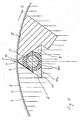
- Figure 1 shows a near-surface part of a printing cylinder 1 of a web-fed rotary printing press for the offset printing of large newspaper editions.
- the cylindrical surface of the printing cylinder is covered with a flexible covering.
- the flexible covering is a rubber blanket 2, which is vulcanized or glued to a flexible plate 3.
- the impression cylinder is accordingly a blanket cylinder.
- the two free ends of the flexible plate 3 are inserted into a clamping channel 6 and secured in the channel 6 by means of a clamping device by clamping.
- the clamping device is formed with channel walls of the channel 6. The two clamped ends need not be the ends of the same plate and are not in many applications.
- the channel 6 extends axially, d. H. parallel to a rotation axis of the cylinder 1, in a near-surface region of the cylinder and forms a narrow channel opening 7 directly on the surface.
- the channel opening 7 is bounded by two boundary edges, namely a leading in the direction of rotation D of the cylinder 1 boundary edge 1v and a trailing Boundary edge 8n.
- the boundary edges 1v and 8n are axially parallel in the circumferential direction.
- the channel 6 widens in cross-section from the boundary edges 1v and 8n to both sides of a radial R which extends through the opening 7 on the axis of rotation of the cylinder 1.
- the opening 7 and the adjoining, the channel 6 delimiting channel walls 4 and 5 are axisymmetric in cross section to the radial R.
- the blanket 2 itself is not inserted in the channel 6, but forms over the channel opening 7 a narrow slot or abut on the channel opening 7 preferably together.
- the clamping device for clamping the ends of the fabric 2, 3 is formed by a arranged in the channel 6 clamping body 10 in combination with the channel channel walls delimiting channel.
- the channel walls are the channel walls 4 and 5 and a further channel wall 9, which each form a counter surface for the clamping body 10.
- the clamping body 10 is supported directly on this, the channel 6 between them enclosing channel walls 4, 5 and 9 from.
- the channel walls 4 and 9 are formed directly by the cylinder 1 itself.
- the channel wall 5 forms a filler 8, which is fixed to the cylinder 1, d. H. not movable, connected, for example, screwed, is.
- the channel wall 4 extends from the channel wall 9 plan to the boundary edge 1v.
- the channel wall 5 extends from the channel wall 9 plane up to the boundary edge 8n.
- the channel walls 4 and 5 each have at the same angle, which should be at least 30 ° and at most 45 °, obliquely to the radial R.
- the clamping body 10 is circular cylindrical. It is a composite body having a core 10i of a core material and a cladding 10a of a cladding material.
- the core material has a greater specific gravity or density than the cladding material.
- the jacket material is elastic and can be, for example, rubber or preferably a plastic, i. H. an elastomer. It has a hardness of 70 ⁇ 10 Shore, with the center value or values closer to the center of 70 Shore being preferred.
- the clamping body 10 is supported directly on the channel walls 4, 5 and 9, d. H. it touches with its surface depending on one of the channel walls 4, 5 and 9 formed counter surface.
- the mating surface formed by the channel wall 4 is referred to as the first mating surface 4, the mating surface formed by the channel wall 5 as the second mating surface 5, and the mating surface formed by the channel wall 9 as the third mating surface 9.
- the support points of the clamping body 10 formed by the mating surfaces 4, 5 and 9 are arranged distributed over the circumference of the clamping body 10. The total of three support points have each other in pairs each an angular distance of less than 180 °, which already results from the selected in the embodiment, advantageous triangular shape of the channel 6. It is particularly advantageous if each two adjacent support points, as in the embodiment, have the same angular distance.
- the clamping body 10 forms depending on the direction of rotation D of the cylinder 1 a nip for the ends of the fabric 2, 3 either with the first mating surface 4 or with the second mating surface 5.
- the clamping gap is formed in the same way between the clamping body 10 and the second mating surface 5. Due to its round surface with the first mating surface 4, the clamping body 10 forms a funnel which opens to the channel opening 7 and facilitates the insertion of the ends of the clothing 2, 3.
- the funnel is shaped in such a way that there is no danger of obstruction during the insertion of the clothing ends.
- the surface of the clamping body forming the clamping gap has a large radius of curvature. If the clamp body 10, as preferred and carried out in all embodiments, in cross-section circular, it means that it should have a large outer diameter. On the other hand, a small cross section of the channel 6 is advantageous. The no longer changeable width of the channel opening 7 after insertion of the filler 8 should be as small as possible to minimize the impact of the cylinder.
- the clamping body of the invention for example, that of the first embodiment and the other embodiments, has at its the nip forming surface has a radius of curvature of at least 7 mm, preferably at least 10 mm.
- the upper limit for the radius of curvature is less critical. However, the radius of curvature should not be more than 20 mm.
- the sheath 10a is sufficiently thick that, due to its material elasticity over the entire circumference of the clamping body 10, it can deflect by the sum of the thicknesses of the two ends of the covering 2, 3.
- the clamping device of the first embodiment has no further possibilities of springing, since the support points for the clamping body 10 are rigidly formed directly by the channel walls, namely the mating surfaces 4, 5 and 9.
- the clamping body 10 should increase the clamping force with rotating cylinder 1 as large a mass and therefore have the highest possible proportion of nuclear material.
- the shell 10a has circumferentially a uniform thickness of at least 3 mm and at most 7 mm.
- the jacket 10a has a thickness of 5 mm and the core has a diameter of 15 mm.
- the clamp body 10 can rotate despite its jacket 10a in the channel 6 about its longitudinal axis D K , whereby the insertion of the ends of the fabric 2, 3 are facilitated in the nip and the removal.
- the actual execution of a rotary motion is not required.
- the ends of the fabric 2, 3 can be inserted and removed even when not rotating clamp body 10.
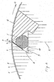
- the clamping device shown in Figure 2 comprises a clamping body 10 which is fully cylindrical of an elastic material, such as rubber or an elastomer formed.
- the elastic material may be the same material as that of the sheath 10a in the first embodiment. Incidentally, the comments on the first embodiment apply.
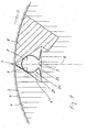
- Figure 3 shows a clamping device of a third embodiment. Also in this clamping device the spring required for clamping the ends of the clothing 2, 3 is formed by a clamping body 20 arranged in the channel 6.
- the cylinder 1, the filler 8 and the channel 6 correspond to the first embodiment and the second embodiment,
- the spring formed by the clamping body 20 is not materially elastic, in contrast to the first and second embodiments.
- Their spring characteristic is based on formula elasticity. It has in cross-section substantially the shape of a Greek " ⁇ " with a resilient arc 21 and two support legs 22.
- the arc 21 extends over the first mating surface 4 and the second mating surface 5 and is open to the third mating surface 9.
- the substantially circular cylindrical arc 21 extends over most of the 360 ° of a closed arc.
- the two ends of the arc 21, ie the two transition regions in which the sheet 21 merges into the two support legs 22, have a tight spacing from the counter surface 9.
- the support legs 22 are only with their expiring ends in contact with the counter surface 9.
- the support legs 22 terminate in front of the inner edges of the channel 6, which forms the counter surface 9 with one of the mating surfaces 4 and 5.
- the support legs 22 can thus slide along the mating surface 9 back and forth, which is for the compression of the clamping body 20 of advantage.
- the clamping body 20 can therefore deflect in two ways, on the one hand by a movement of the two ends of the sheet 21 toward each other and on the other by a resilient movement of the sheet 21 as a whole on the counter surface 9.
- the actually occurring in the clamping of the ends of the clothing 2, 3 adjusting spring movement results from a superposition of both compression possibilities.
- the elastic behavior of the open spring forming clamp body 20 of the function can be better adapted.
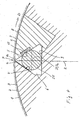
- Figure 4 shows an unclaimed clamping device according to a fourth embodiment.
- a spring 15 directly forms the second mating surface 5, which is opposite to the clamping gap in the circumferential direction of the cylinder 1.
- the channel 6 of the fourth embodiment is polygonal with a total of five each plan channel walls, of which, however, again only the channel walls 4, 5 and 9 form the support points and thus the same numbered counter surfaces 4, 5 and 9 for the clamping body 25.
- a triangular cross section of the channel 6 can also be assumed in the fourth exemplary embodiment.
- the formation of the channel 6 with more than 2 inner edges in cross-section facilitates the production, since the inner edges to be formed by material processing can be rectangular or blunt. For the function of the clamping device, however, this alone does not result in a difference from the first, second and third embodiments.
- the clamping body 25 of the fourth embodiment is a rigid, non-compliant body.
- the clamping body 25 may in particular be a steel body. He is circular cylindrical and full in cross section.
- the mating surface 9, which again forms the channel bottom, also serves as a guideway for the clamp body 25, which moves transversely as a whole when clamping the ends of the clothing 2, 3.
- the clamping body 25 moves on the clamping body 25 Counter surface 9 rolling and / sliding from the first mating surface 4 away and into the second mating surface 5 inside.
- the second mating surface 5 is formed by a material-elastic spring 15.
- the spring 15 is an insert of an elastic material, for example rubber or an elastomer, which is inserted into a depression of the channel wall 5.
- the recess and the insert 15 are shaped so that the insert 15 fits seamlessly into the planar channel wall 5 and, in particular, flatly terminates therewith to form the counter surface 5.
- the insert 15 is a strip which extends at least over the part of the axial length of the channel 6, which occupies the clamping body 25 or axially arranged side by side occupy several clamp body 25.
- the insert 15 is rectangular in cross-section and a total of a cuboid.
- the insert 15 has a thickness and a width measured along the channel wall 5, which are sufficient for the insert 15 to deflect to such an extent that the clamping body 25 extends along the mating surface 9 by the thicknesses of the two ends of the fabric 2, 3 from the first mating surface 4 can move away.
- the elastic restoring force of the insert 15 presses the clamping body 25 with retracted clothing 2, 3 against the ends.
- the displacement of the clamping body 25 is indicated by a parallel to the cylinder radial R straight line.
- the shifted center of gravity is designated SP.
- the formation of the spring 15 in one of the walls of the channel 6 is advantageous for the rotatability of the clamping body 25 and this in turn is advantageous for the insertion and removal of the ends of the fabric 2, 3. Further, the clamping body 25 may have an advantageously large weight, and finally, its production is particularly easy.
- the filler 8 forms the support for the insert 15.
- the creation of the spring by means of the insert 15 is therefore particularly simple.
- Figure 5 shows an unclaimed clamping device of a fifth embodiment, which is derived from that of the fourth exemplary embodiment.
- an insert 14 forms the first mating surface 4 forming the clamping gap with the clamping body 25.
- the insert 14 corresponds to the insert 15 of the fourth exemplary embodiment.
- the two embodiments of Figures 4 and 5 also show in their combination, that the clamping devices of the two embodiments are already rotational direction invariant, d. H. In both embodiments, the ends of the fabric 2, 3 between the clamping body 25 and either either the first mating surface 4 or the second mating surface 5 can be clamped.
- FIG. 6 A likewise not claimed sixth embodiment derived from the fourth and fifth exemplary embodiments is shown in FIG. 6.
- a material-elastic insert 14 forms the first counter-surface 4 and a further material-elastic one Insert 15, the second mating surface 5. Both for the spring formed by means of the insert 14 and for the spring formed by means of the insert 15 apply to the fourth embodiment.
- a clamping device which is invariably rotationally invariant is obtained.
- another filler could form the channel wall 4 or at least one part comprising the insert 14 and thus serve as a carrier for the insert 14.
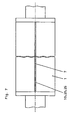
- FIG. 7 is a view of a part of the cylinder 1 comprising the channel 6.
- a single clamping body is arranged in the channel 6, either the clamping body 10, 20 or 25.
Landscapes
- Engineering & Computer Science (AREA)
- Mechanical Engineering (AREA)
- Supply, Installation And Extraction Of Printed Sheets Or Plates (AREA)
- Clamps And Clips (AREA)
- Rotary Presses (AREA)
Claims (23)
- Dispositif de serrage destiné à fixer par serrage un revêtement tendu (2, 3) flexible, d'un cylindre (1) d'une machine à imprimer, qui présente sur une surface périphérique, un canal (6) axial, le dispositif de serrage comprenanta) un corps de serrage (10) qui forme dans le canal (6), avec une première surface antagoniste (4), un interstice de serrage pour au moins une extrémité du revêtement tendu (2, 3), qui s'engage dans une ouverture (7) du canal (6),b) deux parois de canal dirigées vers la première surface conjuguée (4), dont l'une forme une deuxième surface antagoniste (5) et l'autre une troisième surface antagoniste (9) sur lesquelles s'appuie le corps de serrage (10) en y venant en contact,c) le corps de serrage (10) étant réalisé en un matériau élastique, et une force d'élasticité du cops de serrage (10) serrant l'un contre l'autre le corps de serrage (10) et la première surface antagoniste (4), pour, lorsque le revêtement tendu (2, 3) est inséré, fixer par serrage ladite au moins une extrémité du revêtement tendu (2, 3),
caractérisé en ce qued) le corps de serrage (10) est un corps composite ayant une âme (10i) en un matériau d'âme, et ayant une garniture de recouvrement (10a) reliée à l'âme (10i) et réalisée en un matériau de garniture à souplesse élastique, qui a un poids spécifique moindre que le matériau d'âme et qui peut s'écraser élastiquement de l'épaisseur de ladite au moins une extrémité du revêtement tendu (2, 3). - Dispositif de serrage selon la revendication précédente 1, caractérisé en ce que la garniture de recouvrement (10a) enveloppe l'âme (10i).
- Dispositif de serrage selon l'une des revendications précédentes, caractérisé en ce que le matériau de garniture a une dureté Shore de 70 Shore.
- Dispositif de serrage selon l'une des revendications précédentes, caractérisé en ce que les surfaces antagonistes (4, 5, 9) sont formées sur le cylindre (1) ou sur une pièce de remplissage (8) liée de manière immobile au cylindre (1).
- Dispositif de serrage selon l'une des revendications précédentes, caractérisé en ce que les surfaces antagonistes (4, 5, 9) forment des zones d'appui pour le corps de serrage (10), qui sont réparties autour de la périphérie du corps de serrage (10), deux zones d'appui respectivement voisines présentant un écart angulaire de moins de 180°.
- Dispositif de serrage selon l'une des revendications précédentes, caractérisé en ce que ladite au moins une extrémité du revêtement tendu (2, 3) est introduite dans l'interstice de serrage, à l'encontre de la force d'élasticité du corps de serrage (10).
- Dispositif de serrage selon l'une des revendications précédentes, caractérisé en ce que le corps de serrage (10) peut s'écraser élastiquement de l'épaisseur de ladite au moins une extrémité du revêtement tendu (2, 3).
- Dispositif de serrage selon l'une des revendications précédentes, caractérisé en ce que l'ouverture (7) du canal (6) est délimitée, dans la direction périphérique du cylindre (1), par deux bords de délimitation (1v, 8n), en ce que le canal (6) s'élargit à partir des bords de délimitation (1v, 8n) vers les deux directions périphériques du cylindre (1), et en ce qu'une paroi de canal s'étendant jusqu'à l'un des bords de délimitation (1v, 8n) forme la première surface antagoniste (4) et une paroi de canal s'étendant jusqu'à l'autre des bords de délimitation (1v, 8n) forme la deuxième surface antagoniste (5), de sorte que ladite au moins une extrémité du revêtement tendu (2, 3) peut être fixée par serrage, en fonction du sens de rotation (D) du cylindre (1), entre le corps de serrage (10) et soit la première surface antagoniste (4), soit la deuxième surface antagoniste (5).
- Dispositif de serrage selon l'une des revendications précédentes, caractérisé en ce que la première surface antagoniste (4) fait un angle d'au moins 30° avec une radiale (R) passant dans l'ouverture de canal (7) et par l'axe de rotation du cylindre (1).
- Dispositif de serrage selon l'une des revendications précédentes, caractérisé en ce que la deuxième surface antagoniste (5) fait un angle d'au moins 30° avec à une radiale (R) passant dans l'ouverture de canal (7) et par l'axe de rotation du cylindre (1).
- Dispositif de serrage selon l'une des revendications précédentes, caractérisé en ce que l'une des surfaces antagonistes (4, 5, 9) forme une voie de guidage le long de laquelle le corps de serrage (25) est mobile par roulement et/ou glissement, transversalement à l'axe de rotation du cylindre (1).
- Dispositif de serrage selon l'une des revendications précédentes, caractérisé en ce que le corps de serrage (10) a, au moins dans l'état non sollicité, une surface extérieure ronde avec laquelle il forme l'interstice de serrage.
- Dispositif de serrage selon la revendication précédente, caractérisé en ce que la surface extérieure ronde présente un rayon de courbure, qui est plus grand que 7 mm, de préférence plus grand que 10 mm.
- Dispositif de serrage selon l'une des revendications précédentes, caractérisé en ce que le corps de serrage (10) peut tourner dans le canal (6) tout en conservant l'interstice de serrage.
- Dispositif de serrage selon l'une des revendications précédentes, caractérisé en ce que plusieurs revêtements tendus (2, 3) sont tendus côte à côte sur le cylindre (1), et en ce qu'il n'est pas prévu plus d'un corps de serrage (10) par revêtement tendu.
- Dispositif de serrage selon l'une des revendications précédentes, caractérisé en ce que dans le canal (6) n'est disposé qu'un seul corps de serrage (10).
- Dispositif de serrage selon l'une des revendications précédentes, caractérisé en ce que dans le canal sont disposés plusieurs corps de serrage (10) séparés.
- Dispositif de serrage selon l'une des revendications précédentes, caractérisé en ce qu'un insert (14 ; 15) est placé dans une paroi de canal délimitant le canal (6), ou une garniture à souplesse élastique est rapportée sur la paroi de canal.
- Dispositif de serrage selon la revendication précédente, caractérisé en ce que l'insert (14 ; 15) est en un matériau élastique.
- Dispositif de serrage selon la revendication précédente, caractérisé en ce que l'insert (14 ; 15) présente une dureté Shore de 70 Shore ±10 Shore.
- Dispositif de serrage selon l'une des deux revendications précédentes, caractérisé en ce que l'insert (14 ; 15) ou la garniture est pourvu sur une surface dirigée vers le corps de serrage, d'une surface résistante à l'abrasion, et est de préférence revêtu d'un matériau plus dur constituant la surface résistante à l'abrasion.
- Dispositif de serrage selon l'une des revendications précédentes, caractérisé en ce qu'au moins deux des surfaces antagonistes (4, 5, 9) sont formées chacune par un insert (14, 15) ou une garniture selon l'une des trois revendications précédentes.
- Dispositif de serrage selon l'une des revendications précédentes, caractérisé en ce qu'un évidement, qui est formé dans la surface périphérique du cylindre (1), et au moins une pièce de remplissage (8) rapportée dans l'évidement, forment le canal (6) et des bords de délimitation (1v, 8n) de l'ouverture (7) du canal (6), et la pièce de remplissage (8) est pourvue d'un insert (15) ou d'une garniture selon l'une des cinq revendications précédentes.
Applications Claiming Priority (5)
| Application Number | Priority Date | Filing Date | Title |
|---|---|---|---|
| DE2002144944 DE10244944B4 (de) | 2002-09-26 | 2002-09-26 | Klemmvorrichtung zum Klemmen einer flexiblen Bespannung eines Zylinders einer Druckmaschine |
| DE10244945A DE10244945A1 (de) | 2002-09-26 | 2002-09-26 | Vorrichtung zum Befestigen einer flexiblen Bespannung auf Druckzylinder |
| DE10244944 | 2002-09-26 | ||
| DE10244945 | 2002-09-26 | ||
| PCT/CH2003/000638 WO2004028807A1 (fr) | 2002-09-26 | 2003-09-24 | Dispositif de serrage pour fixer par serrage un revetement flexible de cylindre de machine a imprimer |
Publications (2)
| Publication Number | Publication Date |
|---|---|
| EP1545880A1 EP1545880A1 (fr) | 2005-06-29 |
| EP1545880B1 true EP1545880B1 (fr) | 2007-09-19 |
Family
ID=32043961
Family Applications (2)
| Application Number | Title | Priority Date | Filing Date |
|---|---|---|---|
| EP03798029A Withdrawn EP1545881A1 (fr) | 2002-09-26 | 2003-09-24 | Dispositif de serrage servant a fixer un habillage flexible sur un cylindre d'une machine a imprimer |
| EP03798028A Expired - Lifetime EP1545880B1 (fr) | 2002-09-26 | 2003-09-24 | Dispositif de serrage pour fixer par serrage un revetement flexible de cylindre de machine a imprimer |
Family Applications Before (1)
| Application Number | Title | Priority Date | Filing Date |
|---|---|---|---|
| EP03798029A Withdrawn EP1545881A1 (fr) | 2002-09-26 | 2003-09-24 | Dispositif de serrage servant a fixer un habillage flexible sur un cylindre d'une machine a imprimer |
Country Status (6)
| Country | Link |
|---|---|
| US (2) | US7478592B2 (fr) |
| EP (2) | EP1545881A1 (fr) |
| JP (2) | JP2006500249A (fr) |
| AT (1) | ATE373565T1 (fr) |
| DE (1) | DE50308239D1 (fr) |
| WO (2) | WO2004028807A1 (fr) |
Families Citing this family (9)
| Publication number | Priority date | Publication date | Assignee | Title |
|---|---|---|---|---|
| DE102004062598A1 (de) * | 2004-12-24 | 2006-07-06 | Man Roland Druckmaschinen Ag | Vorrichtung für einen Druckzylinder, insbesondere Offsetdruckzylinder für Rollen-Rotationsdruckmaschinen |
| DE102006012760A1 (de) * | 2006-03-17 | 2007-09-20 | Man Roland Druckmaschinen Ag | Vorrichtung zum Befestigen einer flexiblen Bespannung auf einen Druckzylinder |
| US8281716B2 (en) | 2008-12-24 | 2012-10-09 | Printing Research, Inc. | Anti-marking jackets comprised of fluoropolymer and methods of using in offset printing |
| US8578853B2 (en) * | 2008-12-24 | 2013-11-12 | Printing Research, Inc. | Anti-marking jackets comprised of attachment structure and methods of using in offset printing |
| US8220388B2 (en) * | 2008-12-24 | 2012-07-17 | Printing Research, Inc. | Multiple layer anti-marking jackets and methods of using in offset printing |
| US9624040B2 (en) * | 2010-08-25 | 2017-04-18 | Hewlett-Packard Development Company, L.P. | Substrate support |
| US8424453B2 (en) | 2010-09-01 | 2013-04-23 | Printing Research, Inc. | Apparatus and method for adjusting anti-marking jackets |
| US8677899B2 (en) | 2011-01-31 | 2014-03-25 | Printing Research, Inc. | Reversible anti-marking jackets and methods of using |
| US9346258B2 (en) | 2012-05-02 | 2016-05-24 | Printing Research, Inc. | Method for cleaning anti-marking jackets |
Family Cites Families (22)
| Publication number | Priority date | Publication date | Assignee | Title |
|---|---|---|---|---|
| US2900904A (en) | 1953-06-08 | 1959-08-25 | Hantscho George | Printing press rollers |
| US3036354A (en) * | 1960-04-29 | 1962-05-29 | Dorr Oliver Inc | Clamp |
| US3362327A (en) * | 1965-01-28 | 1968-01-09 | Cottrell Company | Cylinder lockup for wrap-around plates and blankets |
| JPS4888103U (fr) * | 1972-01-28 | 1973-10-24 | ||
| DE2620427C3 (de) | 1976-05-08 | 1979-03-08 | Albert-Frankenthal Ag, 6710 Frankenthal | Vorrichtung zum Befestigen von biegsamen Druckplatten auf dem Plattenzylinder von Rotationsdruckmaschinen |
| DE3018249C2 (de) * | 1980-05-13 | 1982-09-09 | M.A.N.- Roland Druckmaschinen AG, 6050 Offenbach | Vorrichtung zum Befestigen von biegsamen Druckplatten auf dem Plattenzylinder von Rotationsdruckmaschinen |
| DK159251C (da) * | 1983-03-12 | 1991-02-18 | Basf Ag | Fremgangsmaade til lukning af spalten mellem en paa et dybtrykapparats trykformcylinder opspaendt dybtrykplades ender, samt indretning ved dybtryksapparatet, til udoevelse af fremgangsmaaden |
| US4577560A (en) * | 1984-08-20 | 1986-03-25 | R. R. Donnelley & Sons Company | Gapless lock-up for offset printing cylinders |
| DE3535138A1 (de) | 1985-10-02 | 1987-04-16 | Frankenthal Ag Albert | Vorrichtung zum befestigen biegsamer druckplatten |
| US5010818A (en) * | 1988-02-29 | 1991-04-30 | Rockwell International Corporation | Tensionless plate lock-up |
| US5123353A (en) * | 1991-07-03 | 1992-06-23 | Rockwell International Corporation | Plate lock-up apparatus |
| DE4232163C3 (de) * | 1992-09-25 | 2001-09-06 | Koenig & Bauer Ag | Vorrichtung zum Aufrechterhalten einer eingestellten Anpressung einer Farbauftragswalze an einem Formzylinder einer Rotationsdruckmaschine |
| DE4238343C2 (de) | 1992-11-13 | 2003-03-27 | Kocher & Beck Gmbh & Co Rotati | Spannvorrichtung für ein Klischee |
| DE4415624A1 (de) | 1994-05-04 | 1995-11-09 | Basf Ag | Verfahren zur Herstellung von strahlungshärtbaren Acrylaten |
| US5485784A (en) * | 1994-06-28 | 1996-01-23 | Walschlaeger, Sr.; Alan R. | Printing plate cylinder with universal lockup apparatus |
| DE19509561C2 (de) | 1995-03-16 | 1997-10-23 | Koenig & Bauer Albert Ag | Vorrichtung zum Klemmen von Platten auf einem Zylinder |
| US5553544A (en) * | 1995-04-12 | 1996-09-10 | Heidelberg Harns Inc. | Plate cylinder |
| DE19606744C2 (de) | 1996-02-23 | 1998-12-10 | Roland Man Druckmasch | Vorrichtung zum Befestigen einer biegsamen Druckplatte |
| DE19652521C1 (de) * | 1996-12-17 | 1998-03-26 | Wifag Maschf | Kanalabdeckung für einen Zylinderkanal eines Zylinders in einer Offsetdruckmaschine |
| DE19703290A1 (de) | 1997-01-30 | 1998-08-06 | Roland Man Druckmasch | Vorrichtung zum Befestigen einer flexiblen Bespannung auf einem Druckzylinder |
| DE20022737U1 (de) | 2000-12-04 | 2002-03-14 | Koenig & Bauer AG, 97080 Würzburg | Vorrichtung zum Befestigen eines Aufzuges auf einem Zylinder |
| DE10108745C1 (de) | 2001-02-23 | 2002-05-23 | Koenig & Bauer Ag | Antrieb für eine Welle zum Klemmen und/oder Spannen von Aufzügen auf einem Zylinder |
-
2003
- 2003-09-24 WO PCT/CH2003/000638 patent/WO2004028807A1/fr active IP Right Grant
- 2003-09-24 JP JP2004538635A patent/JP2006500249A/ja active Pending
- 2003-09-24 EP EP03798029A patent/EP1545881A1/fr not_active Withdrawn
- 2003-09-24 JP JP2004538634A patent/JP2006500248A/ja active Pending
- 2003-09-24 DE DE50308239T patent/DE50308239D1/de not_active Expired - Lifetime
- 2003-09-24 WO PCT/CH2003/000639 patent/WO2004028808A1/fr active Application Filing
- 2003-09-24 EP EP03798028A patent/EP1545880B1/fr not_active Expired - Lifetime
- 2003-09-24 AT AT03798028T patent/ATE373565T1/de not_active IP Right Cessation
- 2003-09-24 US US10/526,451 patent/US7478592B2/en not_active Expired - Fee Related
- 2003-09-24 US US10/526,452 patent/US20050268803A1/en not_active Abandoned
Non-Patent Citations (1)
| Title |
|---|
| None * |
Also Published As
| Publication number | Publication date |
|---|---|
| WO2004028808A1 (fr) | 2004-04-08 |
| EP1545881A1 (fr) | 2005-06-29 |
| DE50308239D1 (de) | 2007-10-31 |
| WO2004028807A1 (fr) | 2004-04-08 |
| ATE373565T1 (de) | 2007-10-15 |
| EP1545880A1 (fr) | 2005-06-29 |
| US7478592B2 (en) | 2009-01-20 |
| JP2006500248A (ja) | 2006-01-05 |
| JP2006500249A (ja) | 2006-01-05 |
| US20050268803A1 (en) | 2005-12-08 |
| US20060150845A1 (en) | 2006-07-13 |
Similar Documents
| Publication | Publication Date | Title |
|---|---|---|
| EP1896260B1 (fr) | Revetement de cylindre d'impression, combinaison d'un cylindre d'impression et d'un revetement de cylindre d'impression, et cylindre d'impression comprenant un revetement de cylindre d'impression fixe par serrage | |
| DE2945280C2 (de) | Zylinder für Rotationsdruckmaschinen | |
| EP0132532B1 (fr) | Cylindre pour une machine rotative d'impression | |
| EP1545880B1 (fr) | Dispositif de serrage pour fixer par serrage un revetement flexible de cylindre de machine a imprimer | |
| EP0445645A1 (fr) | Cylindre d'impression pour machines d'impression rotatives | |
| DE19521645C2 (de) | Einrichtung für eine schlitzförmige Haltevorrichtung | |
| CH615385A5 (en) | Offset rotary printing machine | |
| DE19928882B4 (de) | Zugwalzen/Zugring-Kombination in einer Rollenrotationsdruckmaschine | |
| DE102004031644A1 (de) | Hülsenförmiger Aufzug für einen Zylinder in einer Druckmaschine | |
| EP0193144A2 (fr) | Procédé pour tendre une plaque d'impression sur un cylindre, dispositif de tension correspondant et plaque d'impression s'y rapportant | |
| WO2005110752A2 (fr) | Dispositif de serrage | |
| EP1497126A1 (fr) | Dispositifs de fixation d'au moins un habillage sur un cylindre d'une presse rotative et element d'impression equipe de ces dispositifs | |
| EP0303208B1 (fr) | Dispositif d'obturation du canal entre les extrémités d'une plaque d'impression en creux tendue sur un cylindre de forme | |
| EP2040927B1 (fr) | Dispositif de serrage muni d'une pièce de serrage inclinable | |
| DE102010001755A1 (de) | Vorrichtung zum Befestigen zumindest eines Aufzugs auf einem Zylinder | |
| DE102006032263B3 (de) | Klemmvorrichtung mit überlappenden Klemmmitteln | |
| DE10244944A1 (de) | Klemmvorrichtung zum Klemmen einer flexiblen Bespannung eines Zylinders einer Druckmaschine | |
| DE10244945A1 (de) | Vorrichtung zum Befestigen einer flexiblen Bespannung auf Druckzylinder | |
| DE19509562C1 (de) | Vorrichtung zum Lösen von Platten von einem Zylinder | |
| EP1497125B1 (fr) | Dispositiv constitue par un cylindre d'une machine d'impression rotative | |
| EP2111986A2 (fr) | Dispositif de serrage pour plaques d' impression et cylindre de formage en étant équipé | |
| EP3268223B1 (fr) | Rouleau d'impression, en particulier rouleau d'impression flexographique | |
| WO2003095209A1 (fr) | Element de levage flexible pour cylindre de presse rotative | |
| DE102004049514B4 (de) | Druckeinheit mit wenigstens einem Formzylinder und wenigstens einer Farbauftragswalze | |
| EP1506860A1 (fr) | Procédé pour le montage d'un habillage approché à un cylindre d'une imprimante |
Legal Events
| Date | Code | Title | Description |
|---|---|---|---|
| PUAI | Public reference made under article 153(3) epc to a published international application that has entered the european phase |
Free format text: ORIGINAL CODE: 0009012 |
|
| 17P | Request for examination filed |
Effective date: 20050426 |
|
| AK | Designated contracting states |
Kind code of ref document: A1 Designated state(s): AT BE BG CH CY CZ DE DK EE ES FI FR GB GR HU IE IT LI LU MC NL PT RO SE SI SK TR |
|
| GRAP | Despatch of communication of intention to grant a patent |
Free format text: ORIGINAL CODE: EPIDOSNIGR1 |
|
| GRAS | Grant fee paid |
Free format text: ORIGINAL CODE: EPIDOSNIGR3 |
|
| GRAA | (expected) grant |
Free format text: ORIGINAL CODE: 0009210 |
|
| RAP1 | Party data changed (applicant data changed or rights of an application transferred) |
Owner name: WIFAG MASCHINENFABRIK AG |
|
| AK | Designated contracting states |
Kind code of ref document: B1 Designated state(s): AT BE BG CH CY CZ DE DK EE ES FI FR GB GR HU IE IT LI LU MC NL PT RO SE SI SK TR |
|
| REG | Reference to a national code |
Ref country code: GB Ref legal event code: FG4D Free format text: NOT ENGLISH |
|
| REG | Reference to a national code |
Ref country code: CH Ref legal event code: EP |
|
| REF | Corresponds to: |
Ref document number: 50308239 Country of ref document: DE Date of ref document: 20071031 Kind code of ref document: P |
|
| REG | Reference to a national code |
Ref country code: IE Ref legal event code: FG4D Free format text: LANGUAGE OF EP DOCUMENT: GERMAN |
|
| PG25 | Lapsed in a contracting state [announced via postgrant information from national office to epo] |
Ref country code: FI Free format text: LAPSE BECAUSE OF FAILURE TO SUBMIT A TRANSLATION OF THE DESCRIPTION OR TO PAY THE FEE WITHIN THE PRESCRIBED TIME-LIMIT Effective date: 20070919 |
|
| GBT | Gb: translation of ep patent filed (gb section 77(6)(a)/1977) |
Effective date: 20080201 |
|
| BERE | Be: lapsed |
Owner name: WIFAG MASCHINENFABRIK AG Effective date: 20070930 |
|
| PG25 | Lapsed in a contracting state [announced via postgrant information from national office to epo] |
Ref country code: MC Free format text: LAPSE BECAUSE OF NON-PAYMENT OF DUE FEES Effective date: 20070930 Ref country code: GR Free format text: LAPSE BECAUSE OF FAILURE TO SUBMIT A TRANSLATION OF THE DESCRIPTION OR TO PAY THE FEE WITHIN THE PRESCRIBED TIME-LIMIT Effective date: 20071220 Ref country code: ES Free format text: LAPSE BECAUSE OF FAILURE TO SUBMIT A TRANSLATION OF THE DESCRIPTION OR TO PAY THE FEE WITHIN THE PRESCRIBED TIME-LIMIT Effective date: 20071230 |
|
| REG | Reference to a national code |
Ref country code: IE Ref legal event code: FD4D |
|
| EN | Fr: translation not filed | ||
| PG25 | Lapsed in a contracting state [announced via postgrant information from national office to epo] |
Ref country code: CZ Free format text: LAPSE BECAUSE OF FAILURE TO SUBMIT A TRANSLATION OF THE DESCRIPTION OR TO PAY THE FEE WITHIN THE PRESCRIBED TIME-LIMIT Effective date: 20070919 Ref country code: SK Free format text: LAPSE BECAUSE OF FAILURE TO SUBMIT A TRANSLATION OF THE DESCRIPTION OR TO PAY THE FEE WITHIN THE PRESCRIBED TIME-LIMIT Effective date: 20070919 Ref country code: PT Free format text: LAPSE BECAUSE OF FAILURE TO SUBMIT A TRANSLATION OF THE DESCRIPTION OR TO PAY THE FEE WITHIN THE PRESCRIBED TIME-LIMIT Effective date: 20080219 |
|
| PG25 | Lapsed in a contracting state [announced via postgrant information from national office to epo] |
Ref country code: SE Free format text: LAPSE BECAUSE OF FAILURE TO SUBMIT A TRANSLATION OF THE DESCRIPTION OR TO PAY THE FEE WITHIN THE PRESCRIBED TIME-LIMIT Effective date: 20071219 Ref country code: RO Free format text: LAPSE BECAUSE OF FAILURE TO SUBMIT A TRANSLATION OF THE DESCRIPTION OR TO PAY THE FEE WITHIN THE PRESCRIBED TIME-LIMIT Effective date: 20070919 |
|
| PLBE | No opposition filed within time limit |
Free format text: ORIGINAL CODE: 0009261 |
|
| STAA | Information on the status of an ep patent application or granted ep patent |
Free format text: STATUS: NO OPPOSITION FILED WITHIN TIME LIMIT |
|
| PG25 | Lapsed in a contracting state [announced via postgrant information from national office to epo] |
Ref country code: DK Free format text: LAPSE BECAUSE OF FAILURE TO SUBMIT A TRANSLATION OF THE DESCRIPTION OR TO PAY THE FEE WITHIN THE PRESCRIBED TIME-LIMIT Effective date: 20070919 |
|
| ET | Fr: translation filed | ||
| REG | Reference to a national code |
Ref country code: FR Ref legal event code: EERR Free format text: CORRECTION DE BOPI 08/21 - BREVETS EUROPEENS DONT LA TRADUCTION N A PAS ETE REMISE A L INPI. IL Y A LIEU DE SUPPRIMER : LA MENTION DE LA NON-REMISE. LA REMISE DE LA TRADUCTION EST PUBLIEE DANS LE PRESENT BOPI. |
|
| 26N | No opposition filed |
Effective date: 20080620 |
|
| PG25 | Lapsed in a contracting state [announced via postgrant information from national office to epo] |
Ref country code: BE Free format text: LAPSE BECAUSE OF NON-PAYMENT OF DUE FEES Effective date: 20070930 |
|
| PG25 | Lapsed in a contracting state [announced via postgrant information from national office to epo] |
Ref country code: FR Free format text: LAPSE BECAUSE OF FAILURE TO SUBMIT A TRANSLATION OF THE DESCRIPTION OR TO PAY THE FEE WITHIN THE PRESCRIBED TIME-LIMIT Effective date: 20080523 |
|
| PG25 | Lapsed in a contracting state [announced via postgrant information from national office to epo] |
Ref country code: IE Free format text: LAPSE BECAUSE OF FAILURE TO SUBMIT A TRANSLATION OF THE DESCRIPTION OR TO PAY THE FEE WITHIN THE PRESCRIBED TIME-LIMIT Effective date: 20070919 |
|
| PG25 | Lapsed in a contracting state [announced via postgrant information from national office to epo] |
Ref country code: AT Free format text: LAPSE BECAUSE OF NON-PAYMENT OF DUE FEES Effective date: 20070924 |
|
| PGFP | Annual fee paid to national office [announced via postgrant information from national office to epo] |
Ref country code: NL Payment date: 20080922 Year of fee payment: 6 |
|
| PGFP | Annual fee paid to national office [announced via postgrant information from national office to epo] |
Ref country code: GB Payment date: 20080922 Year of fee payment: 6 |
|
| PG25 | Lapsed in a contracting state [announced via postgrant information from national office to epo] |
Ref country code: EE Free format text: LAPSE BECAUSE OF FAILURE TO SUBMIT A TRANSLATION OF THE DESCRIPTION OR TO PAY THE FEE WITHIN THE PRESCRIBED TIME-LIMIT Effective date: 20070919 |
|
| PG25 | Lapsed in a contracting state [announced via postgrant information from national office to epo] |
Ref country code: SI Free format text: LAPSE BECAUSE OF FAILURE TO SUBMIT A TRANSLATION OF THE DESCRIPTION OR TO PAY THE FEE WITHIN THE PRESCRIBED TIME-LIMIT Effective date: 20070919 |
|
| PG25 | Lapsed in a contracting state [announced via postgrant information from national office to epo] |
Ref country code: CY Free format text: LAPSE BECAUSE OF FAILURE TO SUBMIT A TRANSLATION OF THE DESCRIPTION OR TO PAY THE FEE WITHIN THE PRESCRIBED TIME-LIMIT Effective date: 20070919 |
|
| PG25 | Lapsed in a contracting state [announced via postgrant information from national office to epo] |
Ref country code: BG Free format text: LAPSE BECAUSE OF FAILURE TO SUBMIT A TRANSLATION OF THE DESCRIPTION OR TO PAY THE FEE WITHIN THE PRESCRIBED TIME-LIMIT Effective date: 20071219 Ref country code: LU Free format text: LAPSE BECAUSE OF NON-PAYMENT OF DUE FEES Effective date: 20070924 |
|
| PG25 | Lapsed in a contracting state [announced via postgrant information from national office to epo] |
Ref country code: HU Free format text: LAPSE BECAUSE OF FAILURE TO SUBMIT A TRANSLATION OF THE DESCRIPTION OR TO PAY THE FEE WITHIN THE PRESCRIBED TIME-LIMIT Effective date: 20080320 Ref country code: TR Free format text: LAPSE BECAUSE OF FAILURE TO SUBMIT A TRANSLATION OF THE DESCRIPTION OR TO PAY THE FEE WITHIN THE PRESCRIBED TIME-LIMIT Effective date: 20070919 |
|
| PGFP | Annual fee paid to national office [announced via postgrant information from national office to epo] |
Ref country code: CH Payment date: 20091221 Year of fee payment: 7 |
|
| REG | Reference to a national code |
Ref country code: NL Ref legal event code: V1 Effective date: 20100401 |
|
| GBPC | Gb: european patent ceased through non-payment of renewal fee |
Effective date: 20090924 |
|
| PG25 | Lapsed in a contracting state [announced via postgrant information from national office to epo] |
Ref country code: NL Free format text: LAPSE BECAUSE OF NON-PAYMENT OF DUE FEES Effective date: 20100401 |
|
| PGFP | Annual fee paid to national office [announced via postgrant information from national office to epo] |
Ref country code: DE Payment date: 20100331 Year of fee payment: 7 |
|
| PG25 | Lapsed in a contracting state [announced via postgrant information from national office to epo] |
Ref country code: GB Free format text: LAPSE BECAUSE OF NON-PAYMENT OF DUE FEES Effective date: 20090924 |
|
| PG25 | Lapsed in a contracting state [announced via postgrant information from national office to epo] |
Ref country code: IT Free format text: LAPSE BECAUSE OF NON-PAYMENT OF DUE FEES Effective date: 20070930 |
|
| REG | Reference to a national code |
Ref country code: CH Ref legal event code: PL |
|
| REG | Reference to a national code |
Ref country code: FR Ref legal event code: ST Effective date: 20110531 |
|
| REG | Reference to a national code |
Ref country code: DE Ref legal event code: R119 Ref document number: 50308239 Country of ref document: DE Effective date: 20110401 |
|
| PG25 | Lapsed in a contracting state [announced via postgrant information from national office to epo] |
Ref country code: CH Free format text: LAPSE BECAUSE OF NON-PAYMENT OF DUE FEES Effective date: 20100930 Ref country code: DE Free format text: LAPSE BECAUSE OF NON-PAYMENT OF DUE FEES Effective date: 20110401 Ref country code: LI Free format text: LAPSE BECAUSE OF NON-PAYMENT OF DUE FEES Effective date: 20100930 Ref country code: FR Free format text: LAPSE BECAUSE OF NON-PAYMENT OF DUE FEES Effective date: 20100930 |
|
| PGFP | Annual fee paid to national office [announced via postgrant information from national office to epo] |
Ref country code: FR Payment date: 20091005 Year of fee payment: 7 |