EP1544902A1 - Appareil de nettoyage de plaquette de silicium rotatif - Google Patents
Appareil de nettoyage de plaquette de silicium rotatif Download PDFInfo
- Publication number
- EP1544902A1 EP1544902A1 EP03808884A EP03808884A EP1544902A1 EP 1544902 A1 EP1544902 A1 EP 1544902A1 EP 03808884 A EP03808884 A EP 03808884A EP 03808884 A EP03808884 A EP 03808884A EP 1544902 A1 EP1544902 A1 EP 1544902A1
- Authority
- EP
- European Patent Office
- Prior art keywords
- silicon wafer
- mixed gas
- hydrogen
- coupling pipe
- pipe
- Prior art date
- Legal status (The legal status is an assumption and is not a legal conclusion. Google has not performed a legal analysis and makes no representation as to the accuracy of the status listed.)
- Withdrawn
Links
Images


Classifications
-
- H10P52/00—
-
- H10P72/0408—
-
- H10P70/15—
Definitions
- the present invention relates to a rotation type silicon wafer cleaning device to be used with semiconductor fabrication equipment and the like, and more particularly to a rotation type silicon wafer cleaning device making possible substantial quality improvements in the products by stabilizing the outer surface of the silicon wafer through the improved hydrogen treatment of the outer surface of the silicon wafer through the drying process after cleaning is completed.
- the fabrication of semiconductor elements generally starts with a cleaning treatment of a silicon wafer, and then various treatments such as the formation of a SiO film and the like on the silicon wafer are applied after the cleaning treatment.
- the so-called rotation type silicon wafer cleaning device For cleaning treatment for silicon wafers, the so-called rotation type silicon wafer cleaning device has been broadly employed, in that a silicon wafer placed on the rotation disc installed inside the device body is rotated at high speed (approximately 2000 RPM), and chemical cleaning agents such as hydrofluoric acid and the like are dispersed thereon. After the acid cleaning treatment, a cleaning treatment with pure water is added, and lastly the silicon wafer is dried while rotating at the high speed.
- Si on the so-called surface layer is exposed and hydrogen atoms are bonded with the exposed Si atoms, thus putting the outer surface in a condition wherein the so-called hydrogen termination treatment has been performed.
- the aim is to obtain a highly stable cleaned surface without impure atoms and the like deposited directly onto Si. As the result, it has been said that there will not occur the so-called natural oxidation on the surface layer even when it is left in the air over a long period of time.
- Enhanced stabilization of the outer surface after a cleaning treatment is performed by means of providing the conventional rotation type wafer cleaning device with a novel wafer drying device.
- a first preferred embodiment of the invention is a rotation type silicon wafer cleaning device which conducts the drying and hydrogen termination treatments on the outer surface of the silicon wafer 4 and is provided with a wafer support/rotation driving device 3 inside a case body 2 to clean the silicon wafer with pure water after chemical cleaning, having a silicon wafer drying device comprising a gas supply panel 5 attached to the case body 2 to supply a mixed gas of a hydrogen gas containing the hydrogen gas with more than 0.05 Vol% and an inert gas, a mixed gas supply pipe A which one end is coupled with a gas mixer 14 of the afore-mentioned gas supply panel 5, a mixed gas heating device B to heat the mixed gas inside the afore-mentioned mixed gas supply pipe A, and a hydrogen radical formation apparatus C equipped with a platinum film at the gas contacting part wherewith a high temperature mixed gas heated with the afore-mentioned mixed gas heating device B is
- the second preferred embodiment comprises the first preferred embodiment constructed so that a mixed gas supply pipe A comprises a vertical coupling pipe 7 supported by the case body 2 such that it is free to move up and down and also free to rotate in the direction of the periphery of circle, and a lateral coupling pipe 10 coupled with the other end of the said vertical coupling pipe 7 and supported horizontally, and at the same time, the afore-mentioned vertical coupling pipe 7 is maintained free to move up and down and also free to rotate in the positive and reverse directions by means of a lift/rotation driving mechanism 8.
- the third preferred embodiment comprises the first preferred embodiment constructed so that a sheathed heater installed at a part in a mixed gas supply pipe A is used as a mixed gas heating device B, thus enabling to heat the mixed gas to more than 150°C by employing the said mixed gas heat device B.
- the fourth preferred embodiment comprises the first preferred embodiment so designed that a hydrogen radical formation apparatus C is made to be a hydrogen radical formation/dispersion apparatus 11 equipped with a platinum coated filter fitted at the front end of a mixed gas supply pipe A.
- the first preferred embodiment may be so arranged that the mixing ratio of a hydrogen gas is made to be 0.05 Vol% - 5.0Vol%.
- the second preferred embodiment may be so arranged that the vertical coupling pipe 7 comprises a coupling body 15 and a sheathed heater 16 inserted and fitted therein and is provided with a vertical coupling pipe 9 which allows a mixed gas to run through the space between the inside wall face of the afore-mentioned coupling pipe 15 and the outside wall face of the sheathed heater 16 to be heated with the sheathed heater.
- a heater-mounted lateral coupling pipe 10 comprises a stainless-steel-made outer pipe 17, an inner pipe 19 wherein a spacer 18 is installed for its being fixed to allow the mixed gas to run through, a micro sheathed heater 20 wound around the outer perimeter of the inner pipe, and an aluminum-foil-made cover 21 covering the outer perimeter of the outer pipe 19 around which the micro sheathed heater 20 is wound.
- the second preferred embodiment further may be so arranged that a lift/rotation driving mechanism 8 for a vertical coupling pipe 7 lowers the vertical coupling pipe 7 so that a hydrogen radical formation/dispersion apparatus 11 is maintained and settled at a place whereat the spacing between the lower surface of a platinum coated filter 26 and the upper surface of the silicon wafer 4 facing the filter will be 0.5mm - 3mm.
- the third preferred embodiment may be so arranged that a mixed gas temperature to be supplied to the hydrogen radical formation/dispersion apparatus 11 is maintained at 150°C - 300°C.
- a hydrogen radical formation/dispersion apparatus 11 comprises a reverse-dish-shaped upper body 23 having a mixed gas inlet opening 23a at the center of a upper wall, a reflecting plate 25 installed horizontally on the lower face side of the upper body 23 and having a plurality of gas permeating orifices 25a around the outer perimeter, a short cylinder-shaped filter Flange 24 welded onto the lower end surface of the upper body 23, and a platinum coated filter 26 fixed on the lower face side of the filter flange 24 forming a platinum layer on the porous disc made of a stainless-steel-sintered material.
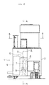
- Figure 1 is a front view of a rotation type silicon wafer cleaning device illustrating an embodiment according to the present invention.
- Figure 2 is a side view of the device.
- Figure 3 is a schematic sectional illustration taken on line A-A in Figure 2.
- Figure 4 is a schematic illustration taken on line B-B in Figure 2. It is to be noted that any type of cleaning devices can be employed as long as it is of a rotation type even though a so-called single wafer processing cleaning device is described in the present invention.
- 1 designates a silicon wafer drying device, 2 a case body, 3 a wafer support/rotation driving mechanism, 4 a silicon wafer, 5 a gas supply panel, 6 a flexible coupling pipe, 7 a vertical coupling pipe, 8 a lift/rotation driving mechanism, 9 a heater-mounted vertical coupling pipe, 10 a heater-mounted lateral coupling pipe, and 11 a hydrogen radical formation/dispersion apparatus.
- A designates a mixed gas supply pipe comprising a flexible coupling pipe 6, a vertical coupling pipe 7, heater-mounted vertical coupling pipe 9, a heater-mounted lateral coupling pipe 10 and the like, B a mixed gas heating device installed on a part of the mixed gas supply pipe A, and C a hydrogen radical formation apparatus installed on the down-stream side of the mixed gas heating device B.
- the afore-mentioned rotation type silicon wafer cleaning device is formed by arranging a silicon wafer drying device 1 comprising a after-mentioned gas supply panel 5, a mixed gas supply pipe A, a mixed gas heating device B, a hydrogen radical formation apparatus C and the like; a support/rotation driving mechanism 3 for the wafer 4 comprising a support disc 3a, a rotation driving part 3b and the like; an automatic setting/removing device (not illustrated) for the wafer 4; an automatic carry-in/carry-out device (not illustrated) for the wafer 4; a jet-spray device (not illustrated) for chemical cleaning agents such as hydrofluoric acid and the like; a jet-spray device (not illustrated) for cleaning water such as pure water and the like; and the like in the case body 2.
- a detailed explanation of a wafer support/rotation driving mechanism 3 comprising the afore-mentioned support disc 3a and a rotation driving part 3b, an automatic setting/removing device for a wafer, and automatic carry-in/carry-out device for the wafer, a jet-spraying device for chemical cleaning agents, a jet-spraying device for cleaning water such as pure water and the like is omitted herewith because they are publicly disclosed.
- the afore-mentioned gas supply panel 5 installed and fixed on the side part inside a case body 2 supplies a mixed gas G of an inert gas with no reaction with hydrogen (such as N 2 gas) and H 2 as illustrated in Figure 5 to a hydrogen radical formation/dispersion apparatus 11 through a mixed gas supply pipe A comprising an the after-mentioned flexible coupling pipe 6, a vertical coupling pipe 7, a heater-mounted vertical coupling pipe 9, a heater-mounted lateral coupling pipe 10 and the like.
- a gas supply panel 5 and the like are housed inside the case body 2.
- heating of the after-mentioned mixed gas G is performed at two separate places, that is, a heater-mounted vertical coupling pipe 9 and a heater-mounted lateral coupling pipe10.
- heating is performed either at the former heater-mounted vertical coupling pipe 9 or at the latter heater-mounted lateral coupling pipe 10.
- a mixed gas heating device B is formed by heaters installed on a vertical coupling pipe 9 and a lateral coupling pipe 10.
- the formation of a mixed gas heating device B can be of any type.
- either an indirect or direct heating method can be applied to heat the mixed gas G.
- the afore-mentioned gas supply panel 5 is formed by a N 2 supply line comprising a pressure regulator 12a, a pressure gauge 12b, a mass flow controller12c and valves 12d and 12e; a H 2 supply line comprising a pressure regulator 13a, a pressure gauge 13b, a mass flow controller 13c and valves 13d and 13e; and a gas mixer 14 for H 2 and N 2 .
- N 2 and H 2 are mixed inside the gas mixer 4, and a mixed gas with N 2 and H 2 containing 0.1Vol% of H 2 is supplied to a hydrogen radical formation/dispersion apparatus 11 at the flow rate of approximately 30SLM (liters per minute under standard conditions).
- a hydrogen radical formation/dispersion apparatus 11 installed at the front end of the down-stream side of the mixed gas supply pipe A is employed for a hydrogen radical formation apparatus C.
- the said hydrogen radical formation apparatus C can be of any construction as long as the gas contacting part for a mixed gas G is equipped with a platinum film.
- the hydrogen radical formation apparatus C can be installed at any place as long as it is installed down-stream of the mixed gas heating device B.
- a mass flow controller 12c for N 2 and a mass flow controller 13c for H 2 employ one for the flow rate of 50SLM and one for the flow rate of 100SCCM respectively.
- SLM and SCCM indicate flow rates expressed in l/min and cc/min respectively under the standard conditions.
- the mixing ratio of H 2 in the mixed gas G is set at approximately 0.1Vol%. It should be noted that it is desired that the mixing ratio of H 2 is set at around 0.01 - 5.0Vol% for the reasons that the level of a so-called hydrogen termination treatment of Si will not be enhanced due to the fact that it is saturated and the volume loss increases even when the mixing ratio of H 2 is raised to higher than 5.0Vol%, while the level of a hydrogen termination treatment of Si will be lowered when the mixing ratio of H 2 is lowered below 0.01%, thereby making it difficult to perform the hydrogen termination treatment properly or making the treatment more time-consuming.
- a mixed gas G with a flow rate of 30SML is supplied to a hydrogen radical formation/dispersion apparatus 11 for 2-3 minutes for the drying treatment of a wafer 4 with the outside diameter of approximately 54mm ⁇ as explained later.
- the outside diameter of a wafer to be treated is not limited to that in the said embodiment, and the flow rate of the mixed gas to be supplied can be appropriately adjusted depending on the outside diameter of the wafer 4 to be cleaned, the time for the drying treatment, a temperature of the mixing gas and the like.
- a stainless-steel flexible tube with the outside diameter of 35mm ⁇ , which inner surface is electrolytically polished, is employed for the afore-mentioned flexible coupling pipe 6, and, as illustrated in Figure 1, and secured removably between the outlet side of the gas supply panel 5 and the lower end part of the vertical coupling pipe 7.
- a stainless-steel tube with the outside diameter of 6.35mm ⁇ , which inner surface is electrolytically polished, is employed for the afore-mentioned vertical coupling pipe 7, and installed in a vertical position inside the case body 1, and supported rotation-free and traveling-free upward and downward thereto.
- the outer peripheral surface of the lower end part of the said vertical coupling pipe 7 is engaged with and supported by the after-mentioned lift/rotation driving mechanism 8, thus making the vertical coupling pipe 7 slide upwards and downwards within a prescribed distance (approximately 200mm in the embodiment), and rotate both forwardly and reverse to the peripheral direction within the prescribed range of an angle (approximately 20° in the embodiment) with the operation of the lift/rotation driving mechanism.
- the after-mentioned heater-mounted vertical coupling pipe 9 is connected to the upper end part of the said vertical coupling pipe 7, thus forming a passage for the flow of a mixed gas G in the vertical direction with both coupling pipes 7 and 8.
- the afore-mentioned lift/rotation driving mechanism 8 allows a vertical coupling pipe 7, a heater-mounted vertical coupling pipe 9 and the like to slide to up and downward directions, and the shaft of a vertical coupling pipe 7 to rotate forwardly and reverse for the angle ⁇ to the peripheral direction (approximately 20° in the embodiment). It is so constituted in the embodiment that a vertical coupling pipe 7 is slid upwards and downwards by means of combining a motor driving part with a rack mechanism, and the vertical coupling pipe 7 rotates forwardly and reverse for the prescribed angle of ⁇ to the peripheral direction by means of combining a motor driving part with a gear mechanism.
- the afore-mentioned lift/rotation driving mechanism 8 can be of any construction such as a lift/rotation driving mechanism 8 with an air cylinder type or an oil pressure cylinder type.
- the afore-mentioned heater-mounted vertical coupling pipe 9 is formed with a coupling pipe body 15 and a sheathed heater 16 housed in the coupling pipe body 15, and a gas inlet opening 15a, a gas outlet opening 15b and a lead wire dragging-out opening 15c are installed on the coupling pipe body 15 respectively.
- a stainless-steel pipe with an inner surface which outer diameter is 19.05mm ⁇ and inner surface is electrolytically polished, is employed for a coupling pipe body 15, and a space made between the outer peripheral surface of a sheathed heater 16 inserted and fitted to the inside thereof and the inner wall surface of a coupling pipe body 15 forms a flow passage.
- a stainless-steel pipe with the outer diameter of 6.35mm ⁇ , which inner wall surface is electrolytically polished is employed for a gas inlet opening 15a and a gas outlet opening 15b.
- the afore-mentioned sheathed heater 16 is formed with a heat generation part 16a, a thermoelectric couple 16b, a lead for input 16c, a lead for the thermoelectric couple 16d, and the like.
- the one having a heat generation part 16a with capacity of 20V and 200W inserted in and fitted to the inside of the stainless-steel pipe with the outer diameter of 12mm ⁇ is employed for the sheathed heater 16.
- the capacity of a sheathed heater 16 and the effective sectional area of a flow passage inside a coupling pipe body 15 are determined appropriately depending on the flow rate of the gas passing through inside a heater-mounted vertical coupling pipe 9 and the degree and velocity of temperature rise and the like of the mixed gas G.
- two pieces of a sheathed heater 16 equipped with a heat generation part 16a with capacity of 200W are employed to heat and raise the mixed gas of approximately 30SLM (H 2 0.1 % and N 2 99.9%) to 100°C - 150°C within 5 - 20 seconds.
- any gas can be employed instead of N 2 to form the mixed gas as long as it does not react with hydrogen.
- a gas inlet opening 15a is installed on the lower part of the outer peripheral surface of the coupling pipe body 15 used for a heater-mounted vertical coupling pipe 9. Therefore, axes of the vertical coupling pipe 7 and the heater-mounted vertical coupling pipe 9 are not lined linearly. However, it is possible that both axes of the vertical coupling pipe 7 and the heater-mounted vertical coupling pipe 9 can be positioned linearly by replacing the position of a lead wire dragging-out opening 15c with the position of a gas inlet opening 15a.
- the afore-mentioned heater-mounted lateral coupling pipe 10 is coupled in a horizontal position with the upper end part of the heater-mounted vertical coupling pipe 9.
- the after-mentioned hydrogen radical formation/dispersion apparatus 11 is installed and fixed.
- a heater is installed inside the hydrogen radical formation/dispersion apparatus 11.
- FIG. 7 is a schematic sectional illustration of a heater-mounted lateral coupling pipe 10 employed for a rotation type wafer cleaning device in the embodiment according to the present invention.
- a heater-mounted lateral coupling pipe 10 in the manner that a stainless-steel-made inner pipe 19 with an outer diameter of 6.35mm ⁇ , which inner wall surface I electrolytically polished, is supported and fixed inside the stainless-steel-made outer pipe 17 with the outer diameter of 19.05mm ⁇ by means of installing a spacer 18, and the outer peripheral surface of the inner pipe 19 is wounded by a micro sheathed heater 20 at an appropriate pitch and the upper part of which is covered by a aluminum foil 21.
- a mixed gas G of approximately 100°C - 120°C and approximately 30SLM supplied through a heater-mounted vertical coupling pipe 9 is heated to approximately 200°C - 250°C while passing through an inner pipe 19 by means of 6 pieces of micro sheathed heater 20 with capacity of 150W, and then supplied into the after-mentioned hydrogen radical formation/dispersion apparatus 11 from its front end part.
- the length of a heater-mounted lateral coupling pipe10 is made approximately 400 - 500mm. Furthermore, as illustrated in Figures 3 and 4, the said heater-mounted lateral coupling pipe 10 travels in the range of approximately 200mm to the up and down directions and also approximately 20° at the angle to the horizontal direction respectively by means of the operation of a lift/rotation driving mechanism.
- a hydrogen radical formation/dispersion apparatus 11 is welded to the front end part of the afire-mentioned heater-mounted lateral coupling pipe 10.
- a radicalized hydrogen-contained nitrogen gas is gushed out from the said hydrogen radical formation/dispersion apparatus 11 toward the outer surface of a silicon wafer 4 positioned thereunder.
- the afore-mentioned hydrogen radical formation/dispersion apparatus 11 comprises a stainless-steel-made and reversed-dish-shaped upper body 23, a disc-shaped reflecting plate 25 welded to the lower end edge of the upper body 23 and the upper end part of the cylinder-shaped filter flange 24, and a disc-shaped platinum coated filter 26 fixed to the lower end edge of the filter flange 24.
- a mixed gas inlet opening 23a on the center of the upper wall surface of the afore-mentioned reverse-dish-shaped upper body 23, and a mixed gas G heated to approximately 150°C - 250°C is led to the inside of the upper body 23 through the said gas inlet opening 23a.
- the afore-mentioned disc-shaped reflecting plate 25 is made of stainless-steel, and there are made a plurality of gas permeating orifices 25a on its outer peripheral part.
- the outer peripheral edge of the said reflecting plate is welded to the upper body 23 in such a state as it being held between the upper end surface of a short cylinder-shaped filter flange 24 and the lower end surface of the upper body 23.
- the afore-mentioned platinum coated filter 26 is formed by coating platinum on the outer surface of the stainless-steel-made filter material.
- pieces of a meshed net-shaped body, of approximately 8 mesh, formed with the stainless-steel-made wire with the outer diameter of 1 ⁇ m are stacked and sintered to make a disc-shaped filtration material with the thickness of approximately 2 - 3mm, the outer diameter of approximately 60mm and the average pore size of 20 ⁇ m, and to form a platinum layer with the thickness of approximately 0.3 ⁇ m on the outer surface of a pore of the said filtration material by means of vapor deposition.
- the method to form a platinum layer on the stainless-steel-made filtration material is not limited to the afore-mentioned method of vapor deposition, but any other methods such as an ion plating method can be applied as long as a platinum layer is formed on the outer surface of the stainless steel.
- a sintered material is employed as the stainless-steel-made filtration material, and the average pore size, the thickness, and the thickness of a platinum layer are set at 20 ⁇ m, approximately 2 - 3mm and approximately 0.3 ⁇ m respectively.
- the method of forming a filtration material, the thickness, the external dimensions and the average pore size of the material as well as the thickness of a platinum layer and the like are not limited to values on the embodiment according to the present invention, but they can be appropriately determined depending on the flow rate and the duration of gushing-out of the gas G, the external dimensions of a silicon wafer 4 and the like.
- a platinum coated filter 26 for the afore-mentioned hydrogen radical formation/dispersion apparatus 11 is horizontally maintained at and fitted to the lower end part of the short cylinder-shaped filter flange 24 by means of a screw stopping mechanism.
- the lower face side of the said platinum coated filter 26 goes down in the neighborhood of the outer surface of the wafer 4 set on the wafer support disc 3a.
- a wafer 4 to be treated for cleaning is automatically set and fitted on a support disc 3a of the wafer cleaning device, and the wafer 4 starts rotating at the high speed (approximately 2000 - 2500RPM) by the operation of the wafer support/rotation driving mechanism 3.
- so-called acid cleaning is performed by a chemical cleaning agent such as hydrofluoric acid and the like being jet-sprayed onto the wafer 4 rotating at the high speed. Furthermore, upon completion of the said acid cleaning, pure water cleaning is performed by pure water being jet-sprayed onto the outer surface of the wafer 4.
- a hydrogen radical formation/dispersion apparatus 11 at the front end of the heater-mounted lateral coupling pipe 10 travels from the retreat position (a dotted line) to the operation position (a solid line) in Figures 3 and 4.
- the gas supply panel 5 starts operating to supply a mixed gas G with H 2 and N 2 containing H 2 of 0.1 % at the flow rate of 30SLM from a gas mixer 14 to a vertical coupling pipe 7. It is desirable that a hydrogen radical formation/dispersion apparatus 11 has completed its traveling to the operational position before starting the supply of the said mixed gas G.
- the mixed gas G supplied to a vertical coupling pipe 7 is heated to approximately 80°C - 150°C with a sheathed heater 16 while passing through a heater-mounted vertical coupling pipe 9. And, the mixed gas G heated inside the vertical coupling pipe 9 is continuously heated while passing inside a heater-mounted lateral coupling pipe 10 to approximately 150°C - 300°C, thus being led to the inside of the hydrogen radical formation/dispersion apparatus 11.
- the mixed gas that gushes in to the inside of the upper body 23 of the hydrogen radical formation/dispersion apparatus 11 through a mixed gas inlet opening 23a is dispersed by collidiing with a reflecting plate 25, and is let to the upper surface side of a platinum coated filter 26 through gas permeating orifices 25a. After the hydrogen gas is converted to hydrogen radical by the catalytic action of platinum while passing through a filter 26, it is then gushed out together with N 2 onto the wafer 4.
- a mixed gas G gushed out onto the afore-mentioned filter 26 is heated to the high temperature of 150°C - 300°C (approximately 250°C in the embodiment according to the present invention).
- a mixing gas G turn to hydrogen radical when the hydrogen in the mixed gas is activated by means of contacting with a platinum catalyst while passing through the filter 26, thus the binding of Hydrogen with Si atoms is remarkably enhanced.
- the radicalization of hydrogen in the afore-mentioned mixed gas G by means of employing platinum catalyst can be sufficiently performed when the temperature of the mixed gas reaches higher than 150°C.
- the temperature of the mixed gas has been raised to 250°C taking some margin into consideration.
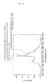
- the limiting temperature to form hydrogen radical is approximately 150°C as illustrated in Figure 8 wherein the relation curve between the reaction rate and the temperature is shown in case that water is produced by the reaction of radicalized hydrogen with oxygen employing platinum as a catalyst.
- the fact that the reaction rate reaches closely 100% when the temperature exceeds approximately 150°C indicates that hydrogen is almost completely radicalized at the temperature of approximately 150°C.
- the spacing of a hydrogen radical formation/dispersion apparatus 11 and a wafer 4 is set for approximately 1 mm. It should be noted that the smaller spacing is the better. Accordingly, sufficient hydrogen termination treatment cannot be expected when the afore-mentioned spacing becomes wider than approximately 3mm because hydrogen radical vanishes between the outer surface of the filter 26 and the outer surface of the wafer 4.
- the afore-mentioned spacing is made smaller than 0.5mm, it becomes inappropriate because of the possible danger of the wafer 4 rotating at the high speed being contacted with the filter 26. Due to this reasons, the afore-mentioned spacing is set at 1 mm in the embodiment according to the present invention.
- the release of the mixed gas G is performed through the afore-mentioned hydrogen radical formation/dispersion apparatus 11 for approximately 2-3 minutes.
- the drying of the Si wafer with the outer diameter of 60mm ⁇ rotating at the speed of 2000RPM is perfectly achieved by releasing the mixed gas G which temperature and flow rate are 250°C and 30SLM respectively, and at the same time nearly perfect hydrogen termination treatment of Si atoms on its outer surface is performed.
- a Si wafer 4 having an outer diameter of 60mm ⁇ is treated for cleaning with hydrofluoric acid and pure water, and rotates at the speed of 2000RPM while its Si surface is completely exposed. And, then a mixed gas with H 2 and N 2 Containing H 2 of 0.1 % is supplied to a hydrogen radical formation/dispersion apparatus 11 at the speed of 30SLM.
- the spacing between the filter 26 and the Si wafer is made 1 mm, thus making the mixed gas G gushed out for 2 minutes continuously through the space.
- a filter 26 having the outer diameter of 54mm ⁇ , the thickness of 2.5mm is formed in the shape of a disc comprising a sintered body made of a stainless-steel-made meshed net body having a pore with an average size of 20 ⁇ m, and the temperature of the mixed gas at an inlet opening of the filter is set at 250°C.
- a Si wafer 4 processed for the same pre-cleaning with hydrofluoric acid and pure water was made to rotate at the speed of 2000RPM, and a N 2 gas of the temperature of 250°C was jet-sprayed onto the outer surface of the Si wafer 4 continuously for 2 minutes using a dispersion apparatus equipped with the identical filter with no platinum coating being done at the flow rate of 30SLM.
- the Si wafer 4 treated for drying was left in the cleaned air for natural oxidation in the comparison test, and discoloration due to the formation of an oxide film was noticed on the outer surface of the silicon wafer after the lapse of approximately 48 hours.
- the degree of hydrogen termination on the silicon outer surface is judged by observing the peak of infrared absorption of Si-H (in the neighborhood of 2200Cm -1 ) by means of the so-called FT-IR (the ATR method).
- a silicon wafer drying device comprising a hydrogen radical formation apparatus C equipped with a platinum film on the gas contacting part, a mixed gas heating device B, a mixed gas supply pipe A, a gas supply panel and the like is installed inside the case body of a rotation type silicon wafer cleaning apparatus, thus drying the wafer by gushing out the mixed gas of hydrogen and inert gas heated to more than 150°C through the afore-mentioned hydrogen radical formation apparatus C to make hydrogen radical by means of the catalytic action with the afore-mentioned platinum coated film, and jet-spraying the mixed gas containing the said hydrogen radical onto the wafer.
- the present invention achieves excellent, practical effects.
Landscapes
- Cleaning Or Drying Semiconductors (AREA)
Applications Claiming Priority (3)
| Application Number | Priority Date | Filing Date | Title |
|---|---|---|---|
| JP2002276818A JP4554146B2 (ja) | 2002-09-24 | 2002-09-24 | 回転式シリコンウエハ洗浄装置 |
| JP2002276818 | 2002-09-24 | ||
| PCT/JP2003/011667 WO2004036637A1 (fr) | 2002-09-24 | 2003-09-11 | Appareil de nettoyage de plaquette de silicium rotatif |
Publications (1)
| Publication Number | Publication Date |
|---|---|
| EP1544902A1 true EP1544902A1 (fr) | 2005-06-22 |
Family
ID=32104925
Family Applications (1)
| Application Number | Title | Priority Date | Filing Date |
|---|---|---|---|
| EP03808884A Withdrawn EP1544902A1 (fr) | 2002-09-24 | 2003-09-11 | Appareil de nettoyage de plaquette de silicium rotatif |
Country Status (10)
| Country | Link |
|---|---|
| US (1) | US7103990B2 (fr) |
| EP (1) | EP1544902A1 (fr) |
| JP (1) | JP4554146B2 (fr) |
| KR (1) | KR100705344B1 (fr) |
| CN (1) | CN100359641C (fr) |
| AU (1) | AU2003264411A1 (fr) |
| CA (1) | CA2465875A1 (fr) |
| IL (2) | IL161793A0 (fr) |
| TW (1) | TWI226661B (fr) |
| WO (1) | WO2004036637A1 (fr) |
Families Citing this family (23)
| Publication number | Priority date | Publication date | Assignee | Title |
|---|---|---|---|---|
| TW200524018A (en) * | 2003-11-20 | 2005-07-16 | Ulvac Inc | Method of cleaning surface of semiconductor substrate, method of manufacturing film, method of manufacturing semiconductor device and semiconductor device |
| US10179351B2 (en) | 2005-02-07 | 2019-01-15 | Planar Semiconductor, Inc. | Method and apparatus for cleaning flat objects with pulsed liquid jet |
| US9799536B2 (en) * | 2005-02-07 | 2017-10-24 | Planar Semiconductor, Inc. | Apparatus and method for cleaning flat objects in a vertical orientation with pulsed liquid jet |
| TWI552797B (zh) * | 2005-06-22 | 2016-10-11 | 恩特葛瑞斯股份有限公司 | 整合式氣體混合用之裝置及方法 |
| US7479460B2 (en) * | 2005-08-23 | 2009-01-20 | Asm America, Inc. | Silicon surface preparation |
| WO2007032057A1 (fr) * | 2005-09-13 | 2007-03-22 | Tadahiro Ohmi | Processus de fabrication d'un dispositif semi-conducteur et appareil de production semi-conducteur |
| US7877895B2 (en) * | 2006-06-26 | 2011-02-01 | Tokyo Electron Limited | Substrate processing apparatus |
| US20080166210A1 (en) * | 2007-01-05 | 2008-07-10 | Applied Materials, Inc. | Supinating cartesian robot blade |
| US7694688B2 (en) | 2007-01-05 | 2010-04-13 | Applied Materials, Inc. | Wet clean system design |
| CN101179009B (zh) * | 2007-11-21 | 2011-09-21 | 上海宏力半导体制造有限公司 | 喷射清洗方法以及装置 |
| CN101740324B (zh) * | 2008-11-25 | 2011-09-28 | 上海华虹Nec电子有限公司 | 硅片清洗机及硅片清洗方法 |
| US9454158B2 (en) | 2013-03-15 | 2016-09-27 | Bhushan Somani | Real time diagnostics for flow controller systems and methods |
| CN104096667A (zh) * | 2013-04-08 | 2014-10-15 | 广达电脑股份有限公司 | 烘胶设备 |
| US10983538B2 (en) | 2017-02-27 | 2021-04-20 | Flow Devices And Systems Inc. | Systems and methods for flow sensor back pressure adjustment for mass flow controller |
| KR102003361B1 (ko) * | 2017-09-19 | 2019-07-24 | 무진전자 주식회사 | 인시튜 건식 세정 방법 및 장치 |
| KR101981738B1 (ko) * | 2017-09-19 | 2019-05-27 | 무진전자 주식회사 | 기판 처리 방법 및 장치 |
| CN110148573B (zh) * | 2019-04-17 | 2020-12-04 | 湖州达立智能设备制造有限公司 | 一种半导体设备工艺腔的晶圆升降装置 |
| CN110335839B (zh) * | 2019-07-05 | 2022-02-22 | 西安奕斯伟材料科技有限公司 | 一种片盒清洗装置及方法 |
| CN111354662A (zh) * | 2020-03-10 | 2020-06-30 | 南通欧贝黎新能源电力股份有限公司 | 一种太阳能电池片制备用硅片去除磷硅玻璃酸洗装置 |
| JP7619800B2 (ja) * | 2020-12-24 | 2025-01-22 | 株式会社アーステクニカ | 造粒乾燥装置及び造粒乾燥方法 |
| KR102916044B1 (ko) * | 2021-03-18 | 2026-01-21 | 에이에스엠 아이피 홀딩 비.브이. | 반도체 처리 사전 세정 방법 및 장치 |
| CN114001546B (zh) * | 2021-11-01 | 2022-09-30 | 华海清科股份有限公司 | 一种晶圆提拉干燥的动态交接方法及晶圆干燥装置 |
| WO2023196103A1 (fr) * | 2022-04-08 | 2023-10-12 | Kulicke And Soffa Industries, Inc. | Systèmes de liaison et procédés de fourniture d'un gaz réducteur sur un système de liaison |
Family Cites Families (5)
| Publication number | Priority date | Publication date | Assignee | Title |
|---|---|---|---|---|
| US5212050A (en) * | 1988-11-14 | 1993-05-18 | Mier Randall M | Method of forming a permselective layer |
| US5129955A (en) * | 1989-01-11 | 1992-07-14 | Dainippon Screen Mfg. Co., Ltd. | Wafer cleaning method |
| JP3436776B2 (ja) * | 1993-08-09 | 2003-08-18 | 忠弘 大見 | ウエハ洗浄装置及び洗浄方法 |
| JP3742451B2 (ja) * | 1996-01-17 | 2006-02-01 | 昌之 都田 | 洗浄方法 |
| JP4375584B2 (ja) * | 1998-07-08 | 2009-12-02 | 財団法人国際科学振興財団 | 乾燥方法 |
-
2002
- 2002-09-24 JP JP2002276818A patent/JP4554146B2/ja not_active Expired - Fee Related
-
2003
- 2003-09-11 CA CA002465875A patent/CA2465875A1/fr not_active Abandoned
- 2003-09-11 AU AU2003264411A patent/AU2003264411A1/en not_active Abandoned
- 2003-09-11 KR KR1020047011263A patent/KR100705344B1/ko not_active Expired - Fee Related
- 2003-09-11 EP EP03808884A patent/EP1544902A1/fr not_active Withdrawn
- 2003-09-11 US US10/498,800 patent/US7103990B2/en not_active Expired - Fee Related
- 2003-09-11 WO PCT/JP2003/011667 patent/WO2004036637A1/fr not_active Ceased
- 2003-09-11 CN CNB03801601XA patent/CN100359641C/zh not_active Expired - Fee Related
- 2003-09-11 IL IL16179303A patent/IL161793A0/xx unknown
- 2003-09-19 TW TW092125997A patent/TWI226661B/zh not_active IP Right Cessation
-
2004
- 2004-05-05 IL IL161793A patent/IL161793A/en not_active IP Right Cessation
Non-Patent Citations (1)
| Title |
|---|
| See references of WO2004036637A1 * |
Also Published As
| Publication number | Publication date |
|---|---|
| JP4554146B2 (ja) | 2010-09-29 |
| TW200409218A (en) | 2004-06-01 |
| CN100359641C (zh) | 2008-01-02 |
| TWI226661B (en) | 2005-01-11 |
| IL161793A0 (en) | 2005-11-20 |
| KR100705344B1 (ko) | 2007-04-10 |
| JP2004119417A (ja) | 2004-04-15 |
| US20050126030A1 (en) | 2005-06-16 |
| WO2004036637A1 (fr) | 2004-04-29 |
| US7103990B2 (en) | 2006-09-12 |
| IL161793A (en) | 2008-12-29 |
| KR20040089117A (ko) | 2004-10-20 |
| CN1596461A (zh) | 2005-03-16 |
| AU2003264411A8 (en) | 2004-05-04 |
| CA2465875A1 (fr) | 2004-04-29 |
| AU2003264411A1 (en) | 2004-05-04 |
Similar Documents
| Publication | Publication Date | Title |
|---|---|---|
| EP1544902A1 (fr) | Appareil de nettoyage de plaquette de silicium rotatif | |
| TW413840B (en) | Method and apparatus for fabricating an integrated circuit | |
| JP5780695B2 (ja) | 薄膜形成装置の洗浄方法、薄膜形成方法及び薄膜形成装置 | |
| KR100729410B1 (ko) | 기판처리방법 및 기판처리장치 | |
| US7836900B2 (en) | Substrate processing system, substrate processing method, recording medium and software | |
| EP0252667A2 (fr) | Procédé de dépôt en phase vapeur | |
| WO2004095559A1 (fr) | Procede de retrait de film d'oxyde de silicium et appareil de traitement | |
| US7829475B2 (en) | Baking method of quartz products, computer program and storage medium | |
| JP4706260B2 (ja) | 被処理体の酸化方法、酸化装置及び記憶媒体 | |
| JP2001223213A (ja) | 半導体のウェハ上に酸化物層を形成するための方法および装置 | |
| JP2001237211A (ja) | 基板処理装置 | |
| WO2002054456A2 (fr) | Solution de rinçage et procedes de rinçage et de sechage permettant d'empecher la formation d'empreintes sur une surface | |
| JP3457049B2 (ja) | 真空容器のベーキング方法 | |
| JP3125280B2 (ja) | Cvd装置のクリーニング方法 | |
| JP4056365B2 (ja) | 基板処理用流体供給装置 | |
| CN113355652B (zh) | 成膜方法 | |
| JP3108466B2 (ja) | 縦型熱処理装置 | |
| JP2006005214A (ja) | シリコンウエーハの熱処理方法 | |
| JP2003051533A (ja) | 半導体装置の製造方法および基板処理装置 | |
| CN109844922B (zh) | 具有用于俘获污染物的装置的竖炉 | |
| JPH09129582A (ja) | 基板表面の乾式洗浄方法 | |
| JPS6123870B2 (fr) | ||
| JP2007142354A (ja) | 薄膜形成装置の洗浄方法、薄膜形成方法及び薄膜形成装置 | |
| KR19980053007A (ko) | 웨이퍼 에칭 장치 | |
| JPH06333867A (ja) | ガス導入管付反応器 |
Legal Events
| Date | Code | Title | Description |
|---|---|---|---|
| PUAI | Public reference made under article 153(3) epc to a published international application that has entered the european phase |
Free format text: ORIGINAL CODE: 0009012 |
|
| 17P | Request for examination filed |
Effective date: 20040629 |
|
| AK | Designated contracting states |
Kind code of ref document: A1 Designated state(s): AT BE BG CH CY CZ DE DK EE ES FI FR GB GR HU IE IT LI LU MC NL PT RO SE SI SK TR |
|
| AX | Request for extension of the european patent |
Extension state: AL LT LV MK |
|
| RIN1 | Information on inventor provided before grant (corrected) |
Inventor name: KAWADA, KOJIC/O FUJIKIN INCORPORATED Inventor name: MORIMOTO, AKIHIROC/O FUJIKIN INCORPORATED Inventor name: IKEDA, NOBUKAZUC/O FUJIKIN INCORPORATED Inventor name: MINAMI, YUKIOC/O FUJIKIN INCORPORATED Inventor name: FUJITA, TAKUMIC/O PRE-TECH CO., LTD. Inventor name: SHIRAI, YASUYUKI Inventor name: OHMI, TADAHIRO |
|
| DAX | Request for extension of the european patent (deleted) | ||
| STAA | Information on the status of an ep patent application or granted ep patent |
Free format text: STATUS: THE APPLICATION HAS BEEN WITHDRAWN |
|
| 18W | Application withdrawn |
Effective date: 20090423 |