EP1544796A2 - Verfahren zur Umrechnung von Abtasterbildkoordinaten einer seltenen Zelle in Microskopkoordinaten unter Verwendung von Photomaskenmarkierungen auf einem Probenmedium - Google Patents
Verfahren zur Umrechnung von Abtasterbildkoordinaten einer seltenen Zelle in Microskopkoordinaten unter Verwendung von Photomaskenmarkierungen auf einem Probenmedium Download PDFInfo
- Publication number
- EP1544796A2 EP1544796A2 EP04029473A EP04029473A EP1544796A2 EP 1544796 A2 EP1544796 A2 EP 1544796A2 EP 04029473 A EP04029473 A EP 04029473A EP 04029473 A EP04029473 A EP 04029473A EP 1544796 A2 EP1544796 A2 EP 1544796A2
- Authority
- EP
- European Patent Office
- Prior art keywords
- coordinates
- coordinate space
- coordinate
- reticle
- scan
- Prior art date
- Legal status (The legal status is an assumption and is not a legal conclusion. Google has not performed a legal analysis and makes no representation as to the accuracy of the status listed.)
- Withdrawn
Links
Images


Classifications
-
- G—PHYSICS
- G01—MEASURING; TESTING
- G01N—INVESTIGATING OR ANALYSING MATERIALS BY DETERMINING THEIR CHEMICAL OR PHYSICAL PROPERTIES
- G01N15/00—Investigating characteristics of particles; Investigating permeability, pore-volume or surface-area of porous materials
- G01N15/10—Investigating individual particles
- G01N15/14—Optical investigation techniques, e.g. flow cytometry
- G01N15/1429—Signal processing
- G01N15/1433—Signal processing using image recognition
-
- G—PHYSICS
- G01—MEASURING; TESTING
- G01N—INVESTIGATING OR ANALYSING MATERIALS BY DETERMINING THEIR CHEMICAL OR PHYSICAL PROPERTIES
- G01N15/00—Investigating characteristics of particles; Investigating permeability, pore-volume or surface-area of porous materials
- G01N15/10—Investigating individual particles
- G01N15/14—Optical investigation techniques, e.g. flow cytometry
- G01N15/1468—Optical investigation techniques, e.g. flow cytometry with spatial resolution of the texture or inner structure of the particle
-
- G—PHYSICS
- G06—COMPUTING OR CALCULATING; COUNTING
- G06T—IMAGE DATA PROCESSING OR GENERATION, IN GENERAL
- G06T7/00—Image analysis
- G06T7/70—Determining position or orientation of objects or cameras
- G06T7/73—Determining position or orientation of objects or cameras using feature-based methods
-
- G—PHYSICS
- G06—COMPUTING OR CALCULATING; COUNTING
- G06V—IMAGE OR VIDEO RECOGNITION OR UNDERSTANDING
- G06V10/00—Arrangements for image or video recognition or understanding
- G06V10/20—Image preprocessing
- G06V10/24—Aligning, centring, orientation detection or correction of the image
-
- G—PHYSICS
- G06—COMPUTING OR CALCULATING; COUNTING
- G06V—IMAGE OR VIDEO RECOGNITION OR UNDERSTANDING
- G06V20/00—Scenes; Scene-specific elements
- G06V20/60—Type of objects
- G06V20/69—Microscopic objects, e.g. biological cells or cellular parts
- G06V20/693—Acquisition
-
- G—PHYSICS
- G01—MEASURING; TESTING
- G01N—INVESTIGATING OR ANALYSING MATERIALS BY DETERMINING THEIR CHEMICAL OR PHYSICAL PROPERTIES
- G01N15/00—Investigating characteristics of particles; Investigating permeability, pore-volume or surface-area of porous materials
- G01N15/01—Investigating characteristics of particles; Investigating permeability, pore-volume or surface-area of porous materials specially adapted for biological cells, e.g. blood cells
-
- G—PHYSICS
- G06—COMPUTING OR CALCULATING; COUNTING
- G06T—IMAGE DATA PROCESSING OR GENERATION, IN GENERAL
- G06T2207/00—Indexing scheme for image analysis or image enhancement
- G06T2207/30—Subject of image; Context of image processing
- G06T2207/30004—Biomedical image processing
- G06T2207/30024—Cell structures in vitro; Tissue sections in vitro
Definitions
- the present exemplary embodiments relate to the imaging arts, and find particular application in conjunction with low and high-density cell detection, locating, and identifying in blood smears, biological assays, and the like across distinct imaging systems, and will be described with particular reference thereto.
- the exemplary embodiments will also find application in imaging, locating and identifying other types of low- or high-density features on various substantially planar surfaces and samples, such as imaging semiconductor wafers, imaging particulate contaminants in fluids or thin solid films, and so forth, with such imaging finding specific uses in the printing arts, electronic arts, medical arts, and other scientific and engineering areas.
- a method for obtaining a position of an object A first coordinate space of an imaging system is defined, and coordinates in a first coordinate space are designated. A second coordinate space of a second imaging system is defined, and the coordinates in the second coordinate space are designated. Using the designated coordinates of the first coordinate space, coordinate conversion parameters are computed. Thereafter, coordinates of at least one object in the first coordinate space are designated, and the first coordinate space coordinates of the object are converted into unique coordinates in the second coordinate space.
- FIGURE 1 shows an imaging apparatus
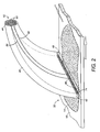
- FIGURE 2 shows the morphed fiber optic bundle.
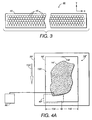
- FIGURE 3 shows an enlarged end view of the morphed fiber optic bundle.
- FIGURES 4A-4C illustrate an embodiment for a higher resolution investigation.
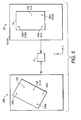
- FIGURE 5 transferring data between two coordinate spaces.
- FIGURE 6 illustrates a flow chart
- FIGURE 7 shows a flow chart
- FIGURE 8 illustrates identified potential rare cells
- FIGURE 9 identifies additional potential rare cells
- FIGURE 10 depicts an additional control box
- FIGURE 11A-11D are used to describe operation of a FAST scanner coordinate conversion process
- FIGURE 12 provides a FAST scanner coordinate conversion output for a reverse direction from FIGURE 11;
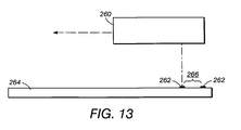
- FIGURE 13 depicts an embodiment where a marking system directly applies marking material to a slide.
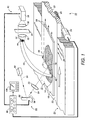
- an imaging apparatus or imager 10 examines a sample 12 such as a biological smear 14 disposed on at least a portion of a surface of a slide 16.
- Imaging apparatus or imager 10 is designed for detection of minute or microscopic material.
- Sample 12 is mounted on imager translation stage, or slide holder, 20 (shown in part) which includes a linearly translatable track 22 that supports the sample 12.
- Motor 24 connects with track 22 via gearing 26 to translate the track 22 and the supported sample 12 along a y-direction (indicated by arrows 28) and a x-direction (indicated by arrows 29).
- fiber optic bundle 40 includes first end 42 that is proximate to sample 12, and second end 44 that is distal from sample 12.
- the first end 42 includes a plurality of first fiber ends 46 arranged substantially parallel to one another in an arrangement that defines a generally linear or high-aspect-ratio rectangular input aperture 48 (best seen schematically in FIGURE 3) with a long dimension aligned with the x-direction.
- Input aperture 48 preferably includes a large number of first fiber ends 46.
- 40,000 fibers each having an approximately 50 micron diameter are used, with a long dimension of approximately 5 cm and a short dimension of about 0.2 cm corresponding to a 25:1 aspect ratio.
- First fiber ends 46 can be arranged in a regular pattern, as shown in FIGURE 3. Alternatively, first fiber ends can be arranged in an irregular or non-periodic array and may have diameters which are greater or less than 50 microns. First fiber ends 46 are oriented substantially perpendicular to the plane of biological smear 14 so as to view smear 14.
- Optical fiber bundle 40 "morphs" or changes cross-sectional dimensions and shape between first end 42 to second end 44 such that second end 44 includes a plurality of second fiber ends 50 (best seen schematically in FIGURE 2) that define a compact, generally circular output aperture 52.
- second fiber ends 50 (best seen schematically in FIGURE 2) that define a compact, generally circular output aperture 52.
- each first fiber end connects with a second fiber end by an individual, distinct fiber having its own waveguiding cladding.
- each fiber can include only a light-transmissive fiber core, and an ambient/core interface functions to waveguide the light.
- a scanning radiation (light) source 60 in a suitable embodiment includes a laser 62 that produces excitation light (radiation beam) 64 at a wavelength or wavelength range selected to excite the material used in marking the biological smear 14.
- Excitation light 64 is angularly scanned by galvanometer 66 that has a reflective surface that rotates (indicated by curved arrows 68) responsive to an electrical input.
- Optional focusing lens 70 focuses the angularly scanned excitation light 64 onto sample 12, and more particularly onto biological smear 14.
- the angular scanning produced by galvanometer 66 translates into a linear sweeping or fast scanning (indicated by arrows 72) of the excitation light on biological smear 14 along linear trajectory 74 arranged below input aperture 48 and parallel to the long dimension of input aperture 48.
- Electronic control unit 80 communicates with galvanometer 66 and translation stage 20 to coordinate linear sweeping or scanning 72 of the radiation beam 64
- the incidence angle of the radiation beam 64 is larger than the collection angle ⁇ of the input aperture 42, specularly reflected radiation is not collected by the input aperture 42.
- the proximate one or few of first fiber ends 46 collect the characteristic luminescence, which is channeled by fiber optic bundle 40 to compact output aperture 52.
- blocking filter 94 is an interference filter with a reflectance peak coinciding with a center wavelength of the radiation beam 64 is employed.
- first lens 92 includes a lens combination, designed using known optical design methods, that collimates light emanating from the output aperture 52 to within a ⁇ 10° angular divergence.
- Second lens 96 focuses the collimated collected light onto photodetector arrangement 98. Combining compact output aperture 52 with focusing optics 92, 96, photodetector 98, provides signal detection for the spatially distributed linear input aperture 48.
- Electronic control unit 80 communicates with galvanometer 66 and translation microscope stage 20 to raster radiation beam 64 across the sample. Characteristic luminescence is collected by input aperture 48, channeled to output aperture 52 by optical fiber bundle 40, and detected by signal detector 90. Electronic control unit 80 receives the detected signal from photodetector 98, and correlates the detected signal with positional coordinates of radiation beam 64 on sample 12.
- Electronic control unit 80 identifies a beam sweep position as a first coordinate in the x-direction, and a position of translation stage 20 as a second orthogonal coordinate in the y-direction, to spatially map out the collected characteristic luminescence intensity as a function of position on the sample 12.
- Imager 10 may accumulate image data irrelevant to the identification of rare cells. At times this noise may be considered as "false positives.” Therefore, filtering procedures may be implemented via electronic control unit 80 and/or other elements of the system 10 to eliminate information not related to rare cells.
- an image event may be classified as a non-rare cell or a rare cell image event by counting the number of pixels of the image event under investigation.
- the shape of an image event is used to filter non-relevant information.
- a further filtering process is tracking the intensity of the image event under investigation.
- FAST fiber array scanning technology
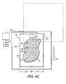
- FIGURE 4A illustrates that sample 12", such as biological smear 14" disposed on at least a portion of a surface of slide 16", is wider than first end 42" which forms an input aperture such input aperture 48 of FIGURE 1.
- Slide 16" incorporates registration marks 130 to assist in obtaining positional information of detected rare cells to be identified and saved.
- first end 42 acts to detect and identify fluorescing cells within first portion 134 of sample 12".
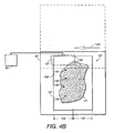
- the translation stage continues until the total area of first portion 134 has been scanned as depicted in FIGURE 4B.
- the scanned sample will require processing following the identifying and localization of the cells of interest. At this point, the sample may be removed for these additional actions.
- controller 80 provides the location or positional information of sample cells 135-139 to automated high-resolution device 146, such as an automated fluorescent microscope. Once the scanning process has been completed (or during the process), automated high-resolution device 146 is provided with the cell position information and it is activated to move and investigate the cells in greater detail.
- the use of the FAST scan process is beneficial in obtaining candidate rare cells to be further investigated by a high resolution viewing device, such as a fluorescent microscope.
- a high resolution viewing device such as a fluorescent microscope.
- the higher resolution device might be found at a separate location, and therefore, sample 12" (12) will be physically moved for further investigation.
- the reticle marks include origin reticle mark 150a, y-axis reticle mark 150b, and x-axis reticle mark 150c. These marks are arranged approximately at the vertexes of a right triangle.
- the FAST scan system 10 will then perform its scanning operation and detect object 152 (e.g., a candidate rare cell). Thereafter, the positional information of reticle marks 150a-150c and of object 152 are obtained. For example, object 152 may be determined to be at a position (a,b) in this first coordinate space.
- sample 12 is transferred to a high resolution system such as microscope 146 of FIGURE 4C. During this transfer to a second coordinate space, sample 12 may become rotated, presented in a different scale, shifted, skewed, or otherwise affected by the transfer.
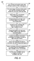
- step 162 a sample including reticle marks and a biological smear is loaded into a rare cell scanning system such as the FAST scan system of FIGURES 1-3. Operation of the FAST scan system causes an image to be generated, including the reticle marks and candidate rare cells.
- a rare cell scanning system such as the FAST scan system of FIGURES 1-3. Operation of the FAST scan system causes an image to be generated, including the reticle marks and candidate rare cells.
- the system At this point generates positional information of the identified candidate rare cells, as well as position information for the origin and x,y reticles of sample 164.
- the generated image may be stored as a rare cell (also called sample) image file for later use.
- a user institutes coordinate conversion procedure 166 to begin the process of converting the image data information from the scanner coordinate space into the high resolution coordinate space.
- coordinate conversion procedure of step 166 is implemented as a piece of software on a computing device, having an interface which permits the user to interact with the conversion process.
- step 168 the locations for the sample's origin and x,y reticle marks in the image pixel space of the scanner coordinate space are designated.
- the sample or rare cell image file is transferred from the FAST scan system to the high resolution device, i.e., microscope, 170.
- the high resolution device i.e., microscope 170.
- known position detecting operations for the high resolution device designate locations of the origin and x,y reticle marks of the sample within the high resolution device coordinate space 172.
- the FAST scan process now computes coordinate conversion parameters for conversion from the scanner coordinate space to the high resolution device coordinate space. Particularly, the system determines any offset shifting in the x- and y-axes, rotation, skew or other positional differences of the sample in the scanner coordinate space location and high resolution coordinate space 174. Using the information from the scanner coordinate space , the locations of candidate rare cells are designated 176. This information is input into the FAST scanner coordinate conversion process. Thereafter, the system applies coordinate conversion parameters previously determined in step 174 to convert the scanner coordinates to high resolution device coordinates 178. Using this information, the high resolution device x-y stage is translated to the corresponding microscope coordinates of suspected rare cells 180.
- Steps 176-180 may be repeated for a plurality of candidate rare cells.
- the process may be designed where a plurality of locations in step 176 may be designated at one time, and the application of the coordinate conversion process in 178 processes all designated locations. Thereafter, translation of the microscope stage automatically moves from a first detected location to a next detected location without a requirement of designating locations of candidate rare cells one at a time.
- step 164 of FIGURE 6, illustrated is expanded detail related to step 164 of FIGURE 6, which includes the generation of the image of the sample, and the locating of the origin, x,y reticle marks, and candidate rare cells.
- the user is provided with an interface which permits for the customization of the image 190.
- step 192 the user determines the data the system will receive. For example, a determination may be made of the scan rate, and degree of light which may be received by detectors. The user may then determine a threshold and/or contrast of the images to be displayed, step 194. Once the images are displayed, the user is provided with a marking mechanism, 196 whereby images of candidate rare cells of interest may be electronically marked.
- the user has the option of storing the image as an image file for later review, and/or use in the high resolution viewing operation.
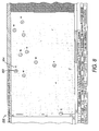
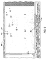
- FIGURES 8 and 9 illustrate exemplary images of displayed candidate rare cells of interest, where the image has been generated in accordance with the FAST scanner system of FIGURES 1-3.
- FIGURE 8 shows image 200 where a user has identified a variety of cells and has used a marking mechanism, i.e., such as a mouse or other known pointing and marking mechanism.
- the system generates circle 202 around a cell of interest, and also attaches an associated number to further identify that cell.
- the user may use a color coding of the numbers and/or circles.
- cells 1, 13 and 15-18 may in this embodiment be designated with a red circles
- cells 4 and 12 are designated with the green circles
- cell 14 is designated with the color blue.
- the colors may represent any identifying characteristic. In one example, red may be of highest interest, green of a secondary, and blue of least interest.
- FIGURE 9 shown is second image 206 similar to the first.
- the main distinction in this is to show the effects of increasing a contrast level, whereby more intense light is generated by the fluorescent coupling. It may be noted, near the bottom of the page, objects 208 have not been designated for further investigation.
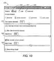
- FIGURE 10 illustrated is a front of user interface 210 which may be used in the interface control system of FIGURE 7. Particularly, the user may select from where light is acquired, i.e., a main channel, a side channel or a combination of the two, 212, 214, 216.
- Slide bars are also provided 218, 220, and 222 to give the user the ability to customize the returned images dependant upon selected threshold and contrast levels, among other items. Intensity, size, two channel intensity ratio, etc., are other characteristics for which controls may be developed.
- the image file i.e., image of sample
- This image file e.g., rare cell image file
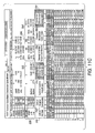
- FIGURES 11A-11 D and the associated description set forth coordinate conversion system 230 which may be used to convert first coordinates, such as rare cell scanner image coordinates to second coordinates, such as microscope coordinates. It is to be understood, however, that the described process is also applicable to other applications where image data is transferred between imaging systems having distinct coordinate spaces.
- Coordinate conversion system 230 includes a variety of input and output blocks, whose functions will be described in greater detail below. At the top of FIGURE 1, shown is Scanner Input block 232, Scanner Parameter blocks 234, 236, Microscope Input block 238 and Microscope Parameter blocks 240, 242, 244. A lower portion of coordinate conversion system 230 includes scanner IMAGE Hit Data block 246, Shifted Scanner Coordinates block 248 and Rotated Scanner Coordinates block 250. Further included is Independent Coordinates block 252 configured to receive data from the previous blocks.
- data from Independent Coordinates block 252 is used by microscope blocks, including Skewed & Scaled 'Scope Coordinates block 254, and Rotated Microscope Coordinates block 256, which function to generate positional data for converted microscope coordinates block 258.
- the first three rows under the aforementioned block components 246-258 are provided for visual verification of the proper operation of the system.
- the values inserted within Input block 232 will be the same values of the first three rows of IMAGE Hit Data block 246.
- the data in the first three rows of converted M-SCOPE Coordinates block 258 will be the same as those in Microscope Input block 238, confirming proper transformation operations.
- Inputs 260 and 262, of IMAGE Hit Data block 246 permit a user to enter location data in the scanner workspace, which then, through operation of the system, generates positional data in the microscope coordinate space. The details of this operation will be expanded upon in the following paragraphs.
- FIGURE 11 A the particular arrangement of components, as illustrated in FIGURE 11 A, are not intended to be a limiting factor as to the concepts of these exemplary embodiments. Rather, the system may be designed in different arrangements from FIGURE 11 A, and even the representation of FIGURE 11A may be altered.
- input block 232 is designed to accept x and y coordinates (values) obtained from the rare cell scanner for, (i) the origin reticle (origin), (ii) the y-reticle (yreticle), (iii) the x-reticle (xreticle), and (iv) the size of the sample (slide.mm).
- coordinate conversion system 230 Upon insertion of this information, coordinate conversion system 230 generates parameter values to convert the rare cell scanner position information of input block 232 into position information of an independent coordinate system.
- nrmlz normalization of the sample (slide.mm) in the x-direction
- nrmlz(x) slide.mm x/rx 'x'
- shift-scan shifted scanner coordinates
- shift-scan y-reticle(x) yreticle x-origin x
- (19) shift-scan x-reticle(y) xreticle y-origin y, ( e.g. , -390, 10 third row of block 248).
- the preceding operations develop coordinate values for the independent coordinate space (i.e. , Independent Coordinates block 252), disassociated from the scanner coordinate space.
- This design permits these independent coordinates to then be transformed into the microscope coordinate space.
- input area 238 has not yet been provided with designated locations of the origin, and the x and y reticles of the microscope coordinate space.
- the system will then use the independent coordinate information of block 252 as a starting point, and generate Skewed and Scaled Microscope Coordinates in ( i.e ., block 254), and Rotated Microscope Coordinates ( i.e. , block 256) and shifted (i.e., block 258) to generate microscope coordinate parameters for Converted Microscope Coordinates block 258.
- an input block is provided to accept x and y coordinates obtained from the microscope system for the origin reticle (origin), y reticle (yreticle), x reticle (xreticle, and the size of the sample (slide.mm).
- the system then develops values for skewed and scaled microscope coordinates of Skewed & Scaled 'Scope Coordinates block 254, rotated microscope coordinates in Rotated Microscope Coordinates block 256, and the shifted microscope coordinate parameters in Converted M-Scope Coordinates block 258.
- rotate-scope origin(x) sk/scl-scope origin(x)*(COS (alpha rad))-sk/scl-scope origin(y)*(SIN(alpha rad))
- rotate-scope origin(y) sk/scl-scope origin(x)*(SIN (alpha rad))+sk/scl-scope origin(y)*(COS(alpha rad)) ( e.g.
- rotate-scope y-reticle(x) sk/scl-scope y-reticle(x) *(COS(alpha rad))-sk/scl-scope y-reticle(y) *(SIN(alpha rad))
- rotate-scope y-reticle(y) sk/scl-scope y-reticle(x) *(SIN(alpha rad))+sk/scl-scope y-reticle(y) *(COS(alpha rad))
- the user may then input either directly or automatically, rare cell scanner coordinates for objects (e.g. , candidate rare cells) such as those shown in FIGURES 9 and 10.
- the x and y coordinates for these objects are entered into columns 260 and 262 of FIGURE 11D, respectively.
- coordinate conversion system 230 permits for the transformation of coordinate points in a first coordinate space to coordinate points in a second coordinate space. While the above discussion focused on transformation from a rare cell image scanner to a microscope coordinate space, coordinate conversion system 230 is not limited to this implementation. Rather, the system is considered to teach a generalized planar object position locator process that may be used for conversion between coordinate spaces of distinct imaging systems.
- the described system takes advantage of an object holder (e.g., slide/sample) with at least three marks, such as reticle marks, arranged approximately at the vertexes of a right triangle.
- a first imaging device then defines a first coordinate space, and the coordinates of the reticle marks in the first coordinate space are designated.
- the sample or image of the sample is then provided to a second imaging device which defines a second coordinate space, and the reticle marks are designated in this second coordinate space.
- the values for coordinate conversion parameters are computed and used to perform transformation operations.
- the disclosed mechanism enables two pieces of equipment with different and perhaps imperfect coordinate spaces to work together, even if their scan rates are not perpendicular to their process directions, and even if the object holder is inadvertently rotated, skewed or otherwise mispositioned.
- the origin reticle and the x-reticle are used to define the horizontal axes
- the origin reticle and the y-reticle are used to define the vertical axes.
- the described steps were recited to include de-shift, de-rotate and de-skewing the position information of the first coordinate space into the independent coordinate space. The system then skews, rotates and shifts the information of the independent coordinate space into the microscope (or target) coordinate space. These steps do not need to be performed in the order described, and other steps may also be used to determine the position of the sample.
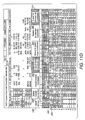
- System 230 is sufficiently modularized such that it works in a reverse direction, as shown by FIGURE 12.
- the coordinates of an object may be located in the second coordinate space (i.e., the microscope HIT Data block) and by insertion of coordinate Information as previously discussed in connection with FIGURES 11A-11 D, the process will convert the information back into coordinates in first coordinate space (i.e., Converted IMAGE Coordinates block).
- FIGURE 11A input block 232 is identified as holding or having input therein x and y coordinates obtained from the rare cell (FAST) scannerforthe, (i) origin reticle, (ii) y-reticle, (iii) x-reticle, and (iv) size of the sample.
- FAST rare cell
- Block 232N of FIGURE 12 holds similar information, but from the microscope coordinate system. This information is used by the described relationships described in parameter blocks 234 and 236 of FIGURE 11A. It is to be noted since the same relationships are used, blocks 234 and 236 are numbered the same in FIGURE 12.
- the input block 238N of FIGURE 12 includes the same input areas as 238 of FIGURE 11A, but is for data related to the scanner image coordinate system. This information is used in parameter blocks 240, 242 and 244, which contain the same relationships as described in connection with FIGURES 11A-11D.
- blocks 246N, 248N and 250N of FIGURE 12 are microscope coordinate system columns which correlate to scanner columns 246, 248 and 250 of FIGURES 11 A-11 D. It is to be noted that in columns 248 and 250, the relationships are the same as that set forth in the discussion of FIGURES 11A-11D, but the values input would be the Microscope HIT Data values of column 246N.
- Independent coordinates column 252N of FIGURE 12 also corresponds to independent coordinate column 252 of FIGURE 11A-11 D. Again, the distinction is that the values being provided are from the microscope coordinate system. As with the discussion related to the preceding columns, similar observations are made with respect to the Skewed and Scaled image coordinates column 254N, and the Rotated image coordinates column 256N. Lastly, column 258N displays the converted image coordinates in the scanner coordinate space.
- This modularized system therefore permits a userto transfer between the two coordinate spaces, rather than only permitting transformations in a single direction.
- the system 230 of FIGURES 11A-11 D and 12 is designed for substantially automated operation.
- the user simply needs to input coordinate information into blocks 232 and 238, and thereafter enter the position information for an object of interest in columns 260 and 262. Thereafter, the system automatically provides the converted microscope coordinate data.
- the described system may be designed where the entry of the information is fully automated. Particularly, inputting of the sample into the imaging system allows, the imaging system to obtain information regarding coordinate positions for block 232, and automatically insert this information into the software program. Thereafter, through normal conveyor operations such as depicted, for example, in FIGURE 4A-4C, the sample may be automatically moved into a higher resolution device such as the microscope system, where the position in the microscope environment is automatically determined and also entered into blocks 238. Thereafter the position date of objects of interest are provided automatically to block 260, 262.
- circular images 202 are shown on an electronic screen image. It is to be appreciated this embodiment is also meant to represent a physical marking on the sample itself. Particularly, as shown in FIGURE 13, automated marking system 260 is moved and positioned to provide marks 262 (whether circular or other form) directly onto slide 264. The marks are placed in association with objects 266 of interest. Using this system, a permanent record of the position of the objects of interest are obtained. The locations for printing are determined in the printing device by a same process as described for determining locations of objects by the microscope system.
- the marking system may be any known marking system capable of printing in small enough amounts, onto appropriate substrates, such as glass.
- Examples of appropriate marking systems may be piezoelectric, acoustic or laser printers, among.others.
- An advantage of using this printing operation is that the samples do not need to be accompanied by a data file of object locations subsequent to the printing. This may be an implementation which finds its usefulness in non-automated clinical settings.
- Another aspect of the present embodiments is to include any known (fixed) non-linear imperfections in the scanner into the conversion process (i.e., scan non-linearity).
- Real-time non-linear imperfections may also be addressed in the conversion process by having the described position measuring system perform real-time position measuring.
Landscapes
- Engineering & Computer Science (AREA)
- Physics & Mathematics (AREA)
- General Physics & Mathematics (AREA)
- Chemical & Material Sciences (AREA)
- General Health & Medical Sciences (AREA)
- Theoretical Computer Science (AREA)
- Health & Medical Sciences (AREA)
- Life Sciences & Earth Sciences (AREA)
- Pathology (AREA)
- Biochemistry (AREA)
- Immunology (AREA)
- Multimedia (AREA)
- Dispersion Chemistry (AREA)
- Analytical Chemistry (AREA)
- Computer Vision & Pattern Recognition (AREA)
- Molecular Biology (AREA)
- Biomedical Technology (AREA)
- Signal Processing (AREA)
- Investigating, Analyzing Materials By Fluorescence Or Luminescence (AREA)
- Length Measuring Devices By Optical Means (AREA)
- Investigating Or Analysing Materials By Optical Means (AREA)
- Microscoopes, Condenser (AREA)
- Image Input (AREA)
Applications Claiming Priority (2)
| Application Number | Priority Date | Filing Date | Title |
|---|---|---|---|
| US740972 | 2003-12-19 | ||
| US10/740,972 US7305112B2 (en) | 2002-10-15 | 2003-12-19 | Method of converting rare cell scanner image coordinates to microscope coordinates using reticle marks on a sample media |
Publications (2)
| Publication Number | Publication Date |
|---|---|
| EP1544796A2 true EP1544796A2 (de) | 2005-06-22 |
| EP1544796A3 EP1544796A3 (de) | 2015-06-24 |
Family
ID=34523216
Family Applications (1)
| Application Number | Title | Priority Date | Filing Date |
|---|---|---|---|
| EP04029473.8A Withdrawn EP1544796A3 (de) | 2003-12-19 | 2004-12-13 | Verfahren zur Umrechnung von Abtasterbildkoordinaten einer seltenen Zelle in Microskopkoordinaten unter Verwendung von Photomaskenmarkierungen auf einem Probenmedium |
Country Status (3)
| Country | Link |
|---|---|
| US (1) | US7305112B2 (de) |
| EP (1) | EP1544796A3 (de) |
| JP (2) | JP2005181312A (de) |
Families Citing this family (42)
| Publication number | Priority date | Publication date | Assignee | Title |
|---|---|---|---|---|
| US7113624B2 (en) | 2002-10-15 | 2006-09-26 | Palo Alto Research Center Incorporated | Imaging apparatus and method employing a large linear aperture |
| US20060109274A1 (en) * | 2004-10-28 | 2006-05-25 | Accelerated Pictures, Llc | Client/server-based animation software, systems and methods |
| US7280261B2 (en) * | 2004-12-20 | 2007-10-09 | Palo Alto Research Center Incorporated | Method of scanning and light collection for a rare cell detector |
| US7286224B2 (en) * | 2004-12-21 | 2007-10-23 | Palo Alto Research Center Incorporated | Time-multiplexed scanning light source for multi-probe, multi-laser fluorescence detection systems |
| EP1984030B1 (de) * | 2006-01-30 | 2013-05-08 | The Scripps Research Institute | Verfahren für den nachweis zirkulierender tumorzellen und verfahren zur diagnostizierung von krebs bei einem säuger |
| US8821799B2 (en) | 2007-01-26 | 2014-09-02 | Palo Alto Research Center Incorporated | Method and system implementing spatially modulated excitation or emission for particle characterization with enhanced sensitivity |
| US9164037B2 (en) | 2007-01-26 | 2015-10-20 | Palo Alto Research Center Incorporated | Method and system for evaluation of signals received from spatially modulated excitation and emission to accurately determine particle positions and distances |
| US7936463B2 (en) | 2007-02-05 | 2011-05-03 | Palo Alto Research Center Incorporated | Containing analyte in optical cavity structures |
| US7633629B2 (en) | 2007-02-05 | 2009-12-15 | Palo Alto Research Center Incorporated | Tuning optical cavities |
| US7817276B2 (en) * | 2007-02-05 | 2010-10-19 | Palo Alto Research Center Incorporated | Distinguishing objects |
| US8153949B2 (en) * | 2008-12-18 | 2012-04-10 | Palo Alto Research Center Incorporated | Obtaining sensing results indicating time variation |
| US7763856B2 (en) * | 2008-01-31 | 2010-07-27 | Palo Alto Research Center Incorporated | Producing time variation in emanating light |
| US8263955B2 (en) * | 2008-12-18 | 2012-09-11 | Palo Alto Research Center Incorporated | Causing relative motion |
| US7817254B2 (en) | 2008-01-30 | 2010-10-19 | Palo Alto Research Center Incorporated | Obtaining information from time variation of sensing results |
| US8629981B2 (en) | 2008-02-01 | 2014-01-14 | Palo Alto Research Center Incorporated | Analyzers with time variation based on color-coded spatial modulation |
| US8373860B2 (en) * | 2008-02-01 | 2013-02-12 | Palo Alto Research Center Incorporated | Transmitting/reflecting emanating light with time variation |
| US20110017915A1 (en) * | 2009-07-23 | 2011-01-27 | Palo Alto Research Center Incorporated | Drift scanner for rare cell detection |
| EP3385716A3 (de) | 2009-10-21 | 2019-01-09 | The Scripps Research Institute | Verfahren zur verwendung nicht seltener zellen zur erkennung seltener zellen |
| US8331738B2 (en) * | 2010-03-24 | 2012-12-11 | Xerox Corporation | Reducing buffer size requirements in an electronic registration system |
| US9129371B2 (en) * | 2010-06-25 | 2015-09-08 | Cireca Theranostics, Llc | Method for analyzing biological specimens by spectral imaging |
| US9025850B2 (en) * | 2010-06-25 | 2015-05-05 | Cireca Theranostics, Llc | Method for analyzing biological specimens by spectral imaging |
| US9111343B2 (en) | 2011-01-18 | 2015-08-18 | Roche Diagnostics Hematology, Inc. | Microscope slide coordinate system registration |
| CN103430077B (zh) * | 2011-01-18 | 2016-03-16 | 体质医学股份有限公司 | 显微镜载玻片坐标系对齐方法和显微镜系统 |
| US9029800B2 (en) | 2011-08-09 | 2015-05-12 | Palo Alto Research Center Incorporated | Compact analyzer with spatial modulation and multiple intensity modulated excitation sources |
| US8723140B2 (en) | 2011-08-09 | 2014-05-13 | Palo Alto Research Center Incorporated | Particle analyzer with spatial modulation and long lifetime bioprobes |
| JP5727614B2 (ja) * | 2011-08-25 | 2015-06-03 | グローリー株式会社 | 紙葉類識別装置及びライトガイドケース |
| CN102445162B (zh) * | 2011-09-21 | 2013-06-05 | 上海大学 | 一种旋转激光束呈锥面扫描的测量装置的参数标定方法 |
| CN104094116B (zh) | 2012-01-24 | 2017-05-31 | 辉瑞公司 | 在哺乳动物个体中检测5t4阳性循环肿瘤细胞的方法和诊断5t4阳性癌症的方法 |
| WO2013177617A1 (en) * | 2012-05-29 | 2013-12-05 | Macquarie University | Two-directional scanning for luminescence microscopy |
| WO2015089113A1 (en) * | 2013-12-09 | 2015-06-18 | North Carolina State University | Methods, systems, and computer readable media for measuring and correcting drift distortion in images obtained using a scanning microscope |
| US10147180B2 (en) | 2013-12-19 | 2018-12-04 | Axon Dx, Llc | Cell detection, capture and isolation methods and apparatus |
| EA201691496A1 (ru) | 2014-01-27 | 2016-12-30 | Эпик Сайенсиз, Инк. | Диагностика биомаркеров рака предстательной железы с помощью циркулирующих опухолевых клеток |
| WO2015127008A1 (en) | 2014-02-21 | 2015-08-27 | Epic Sciences, Inc. | Methods for analyzing rare circulating cells |
| JP6562626B2 (ja) * | 2014-12-10 | 2019-08-21 | キヤノン株式会社 | 顕微鏡システム |
| JP6562627B2 (ja) * | 2014-12-10 | 2019-08-21 | キヤノン株式会社 | 顕微鏡システム |
| US10460439B1 (en) | 2015-08-12 | 2019-10-29 | Cireca Theranostics, Llc | Methods and systems for identifying cellular subtypes in an image of a biological specimen |
| US10649198B2 (en) | 2016-03-11 | 2020-05-12 | Battelle Memorial Institute | Sample processing and analysis methods and apparatus |
| US11561221B2 (en) | 2018-05-02 | 2023-01-24 | Trustees Of Boston University | Dynamic tracking of captured targets for enhanced digital biosensing |
| KR102280538B1 (ko) * | 2019-11-18 | 2021-07-22 | 한양대학교 산학협력단 | 연계형 현미경의 동일 위치 추적을 위한 시스템 및 그의 동작 방법 |
| CN111598133B (zh) * | 2020-04-22 | 2022-10-14 | 腾讯医疗健康(深圳)有限公司 | 基于人工智能的图像显示方法、装置、系统、设备及介质 |
| CN111855578B (zh) * | 2020-08-14 | 2023-10-03 | 杭州医派智能科技有限公司 | 一种病理切片扫描仪 |
| JP2022066928A (ja) * | 2020-10-19 | 2022-05-02 | 日本電子株式会社 | 座標リンケージシステム及び座標リンケージ方法 |
Citations (1)
| Publication number | Priority date | Publication date | Assignee | Title |
|---|---|---|---|---|
| US6040096A (en) * | 1995-12-19 | 2000-03-21 | Nikon Corporation | Mask substrate, projection exposure apparatus equipped with the mask substrate, and a pattern formation method utilizing the projection exposure apparatus |
Family Cites Families (60)
| Publication number | Priority date | Publication date | Assignee | Title |
|---|---|---|---|---|
| JPS50154013A (de) * | 1974-06-01 | 1975-12-11 | ||
| US4002829A (en) * | 1974-08-29 | 1977-01-11 | W. R. Grace & Co. | Autosynchronous optical scanning and recording laser system with fiber optic light detection |
| US3970841A (en) * | 1974-11-25 | 1976-07-20 | Green James E | Method and apparatus for dual resolution analysis of a scene |
| CH620297A5 (en) * | 1976-05-04 | 1980-11-14 | Green James E | Method for the optical analysis of a sample in a double-resolution apparatus, and apparatus for implementation thereof |
| US4600951A (en) * | 1983-12-20 | 1986-07-15 | At&T Technologies, Inc. | Scanning sample, signal generation, data digitizing and retiming system |
| US4556903A (en) * | 1983-12-20 | 1985-12-03 | At&T Technologies, Inc. | Inspection scanning system |
| US4721851A (en) * | 1985-04-30 | 1988-01-26 | Ricoh Company, Ltd. | Image reading device using fiber optic bundles configured differently at each end |
| JPS61251364A (ja) * | 1985-04-30 | 1986-11-08 | Ricoh Co Ltd | 画像サンプリング装置 |
| JPS62206961A (ja) * | 1986-03-06 | 1987-09-11 | Ricoh Co Ltd | 画像読取装置 |
| US4741043B1 (en) * | 1985-11-04 | 1994-08-09 | Cell Analysis Systems Inc | Method of and apparatus for image analyses of biological specimens |
| US4886975A (en) * | 1986-02-14 | 1989-12-12 | Canon Kabushiki Kaisha | Surface examining apparatus for detecting the presence of foreign particles on two or more surfaces |
| US4875780A (en) * | 1988-02-25 | 1989-10-24 | Eastman Kodak Company | Method and apparatus for inspecting reticles |
| US4849645A (en) * | 1988-03-04 | 1989-07-18 | American Telephone And Telegraph Company | Substrate inspection system having two scattered light detecting bundles orthogonally positioned to each other |
| EP0352026A3 (de) * | 1988-07-19 | 1991-02-06 | Ruby Pauline Bonderman | Lamelle zur Kontrolle oder Kalibrierung mit mehreren Feldern mit verschiedenen Analysestoffen oder Konzentrationen an Analysestoff und Verfahren und Gerät zu deren Herstellung |
| US4941309A (en) * | 1989-03-02 | 1990-07-17 | Certainteed Corporation | Panel packaging system |
| JPH0375507A (ja) * | 1989-08-17 | 1991-03-29 | Hitachi Ltd | パターン検査方法およびその装置 |
| US5315993A (en) * | 1990-02-16 | 1994-05-31 | The Boc Group, Inc. | Luminescence monitoring with modulation frequency multiplexing |
| US5103490A (en) * | 1990-06-13 | 1992-04-07 | National Computer Systems, Inc. | Method and apparatus for storing and merging multiple optically scanned images |
| JPH04296642A (ja) | 1991-03-27 | 1992-10-21 | Ricoh Co Ltd | 試料表面欠陥検出装置 |
| US5220617A (en) * | 1991-09-04 | 1993-06-15 | International Business Machines Corporation | Method and apparatus for object inspection |
| US5216485A (en) * | 1991-09-04 | 1993-06-01 | International Business Machines Corporation | Advanced via inspection tool (avit) |
| US5798831A (en) * | 1991-12-19 | 1998-08-25 | Nikon Corporation | Defect inspecting apparatus and defect inspecting method |
| JPH06148085A (ja) | 1992-11-12 | 1994-05-27 | Sony Corp | ウェハ異物検査方法およびウェハ異物検査装置 |
| US5313542A (en) * | 1992-11-30 | 1994-05-17 | Breault Research Organization, Inc. | Apparatus and method of rapidly measuring hemispherical scattered or radiated light |
| US6278957B1 (en) * | 1993-01-21 | 2001-08-21 | Nikon Corporation | Alignment method and apparatus therefor |
| US5651047A (en) * | 1993-01-25 | 1997-07-22 | Cardiac Mariners, Incorporated | Maneuverable and locateable catheters |
| JPH06250094A (ja) * | 1993-02-25 | 1994-09-09 | Nikon Corp | 顕微鏡のスライドガラス位置決め方法及び装置 |
| US5471066A (en) * | 1993-08-26 | 1995-11-28 | Nikon Corporation | Defect inspection apparatus of rotary type |
| US5732162A (en) * | 1993-10-28 | 1998-03-24 | Xerox Corporation | Two dimensional linearity and registration error correction in a hyperacuity printer |
| JP3425615B2 (ja) * | 1994-03-24 | 2003-07-14 | 科学技術庁長官官房会計課長 | 走査型近視野原子間力顕微鏡 |
| JPH07333513A (ja) * | 1994-06-03 | 1995-12-22 | Olympus Optical Co Ltd | 標本マーキング装置 |
| GB9418981D0 (en) * | 1994-09-21 | 1994-11-09 | Univ Glasgow | Apparatus and method for carrying out analysis of samples |
| JP3007540B2 (ja) * | 1994-10-17 | 2000-02-07 | 浜松ホトニクス株式会社 | 画像表示装置 |
| JP3011633B2 (ja) * | 1995-03-15 | 2000-02-21 | 科学技術振興事業団 | 多波長光光学顕微鏡 |
| JP3164989B2 (ja) * | 1994-12-28 | 2001-05-14 | 科学技術振興事業団 | 試料観察方法および多波長光光学顕微鏡 |
| US5835262A (en) * | 1994-12-28 | 1998-11-10 | Research Development Corporation Of Japan | Multi-wavelength optical microscope |
| JP3571819B2 (ja) * | 1995-01-09 | 2004-09-29 | 富士写真フイルム株式会社 | 生化学画像解析装置 |
| JP3614529B2 (ja) * | 1995-09-27 | 2005-01-26 | Ntn株式会社 | 計測装置の演算パラメータ計測方法、および計測装置 |
| JPH09145631A (ja) | 1995-11-29 | 1997-06-06 | Nikon Corp | 表面異物検査装置 |
| US5825483A (en) * | 1995-12-19 | 1998-10-20 | Cognex Corporation | Multiple field of view calibration plate having a reqular array of features for use in semiconductor manufacturing |
| US5801390A (en) * | 1996-02-09 | 1998-09-01 | Nikon Corporation | Position-detection method and apparatus with a grating mark |
| JPH10232229A (ja) * | 1997-02-20 | 1998-09-02 | Olympus Optical Co Ltd | サイトメータ |
| JP3387783B2 (ja) * | 1997-07-04 | 2003-03-17 | 日立ソフトウエアエンジニアリング株式会社 | スキャナ装置 |
| JPH1154407A (ja) * | 1997-08-05 | 1999-02-26 | Nikon Corp | 位置合わせ方法 |
| US6545334B2 (en) * | 1997-12-19 | 2003-04-08 | Imec Vzw | Device and a method for thermal sensing |
| EP1060368A1 (de) * | 1998-02-12 | 2000-12-20 | Hamilton Thorne Research | Kolorimeter und prüfungsvorrichtung |
| ATE296677T1 (de) * | 1998-08-28 | 2005-06-15 | Febit Ag | Träger für analytbestimmungsverfahren und verfahren zur herstellung des trägers |
| JP3689584B2 (ja) * | 1999-03-31 | 2005-08-31 | サッポロビール株式会社 | 観察装置の位置設定手段における座標変換方法及び座標変換手段を備える観察装置 |
| JP2001101410A (ja) * | 1999-09-28 | 2001-04-13 | Suzuki Motor Corp | 変換行列データ生成方法及び較正治具並びに三次元計測システム |
| JP4278800B2 (ja) * | 1999-10-27 | 2009-06-17 | 株式会社ミツトヨ | 撮像空間の幾何学的歪み解消方法 |
| ES2283347T3 (es) * | 1999-10-29 | 2007-11-01 | Cytyc Corporation | Aparato y procedimiento para verificar la localizacion de areas de interes dentro de una muestra en un sistema de formacion de imagenes. |
| CN1311436A (zh) * | 2000-03-01 | 2001-09-05 | 上海和泰光电科技有限公司 | 旋转平台上的生物芯片荧光图象的读取 |
| JP4560898B2 (ja) * | 2000-06-12 | 2010-10-13 | ソニー株式会社 | 検査装置及び検査方法 |
| US6582363B2 (en) * | 2000-08-25 | 2003-06-24 | Pentax Corporation | Video endoscope system and illumination optical system |
| EP2363828A1 (de) * | 2000-10-24 | 2011-09-07 | Cyntellect, Inc. | Vorrichtung zur gezielten Bestimmung von Zellen in einer dreidimensionalen Probe |
| US20020085744A1 (en) * | 2000-11-17 | 2002-07-04 | Molecular Diagnostics, Inc. | Evaluation of microscope slides |
| US7072034B2 (en) * | 2001-06-08 | 2006-07-04 | Kla-Tencor Corporation | Systems and methods for inspection of specimen surfaces |
| JP4423811B2 (ja) * | 2001-04-27 | 2010-03-03 | コニカミノルタセンシング株式会社 | 三次元形状測定システム及び三次元形状測定方法 |
| US6636623B2 (en) * | 2001-08-10 | 2003-10-21 | Visiongate, Inc. | Optical projection imaging system and method for automatically detecting cells with molecular marker compartmentalization associated with malignancy and disease |
| JP3902939B2 (ja) * | 2001-10-26 | 2007-04-11 | 株式会社日立ハイテクノロジーズ | 標本中の微小領域測定装置及び方法 |
-
2003
- 2003-12-19 US US10/740,972 patent/US7305112B2/en not_active Expired - Lifetime
-
2004
- 2004-12-10 JP JP2004358696A patent/JP2005181312A/ja active Pending
- 2004-12-13 EP EP04029473.8A patent/EP1544796A3/de not_active Withdrawn
-
2012
- 2012-04-02 JP JP2012083670A patent/JP5563614B2/ja not_active Expired - Fee Related
Patent Citations (1)
| Publication number | Priority date | Publication date | Assignee | Title |
|---|---|---|---|---|
| US6040096A (en) * | 1995-12-19 | 2000-03-21 | Nikon Corporation | Mask substrate, projection exposure apparatus equipped with the mask substrate, and a pattern formation method utilizing the projection exposure apparatus |
Non-Patent Citations (1)
| Title |
|---|
| AUTOSCAN SYSTEMS PTY. LTD.: "TrakScan for Windows v1.1 User Manual", 9 February 2001 (2001-02-09), XP055478844, Retrieved from the Internet <URL:http://www.autoscan.com.au/pdf/TrakScan_UserManual_v1_1.PDF> [retrieved on 20180528] * |
Also Published As
| Publication number | Publication date |
|---|---|
| US20040131241A1 (en) | 2004-07-08 |
| US7305112B2 (en) | 2007-12-04 |
| JP5563614B2 (ja) | 2014-07-30 |
| JP2005181312A (ja) | 2005-07-07 |
| JP2012177697A (ja) | 2012-09-13 |
| EP1544796A3 (de) | 2015-06-24 |
Similar Documents
| Publication | Publication Date | Title |
|---|---|---|
| EP1544796A2 (de) | Verfahren zur Umrechnung von Abtasterbildkoordinaten einer seltenen Zelle in Microskopkoordinaten unter Verwendung von Photomaskenmarkierungen auf einem Probenmedium | |
| US10295814B2 (en) | Light sheet microscope and method for operating same | |
| US8228495B2 (en) | Defects inspecting apparatus and defects inspecting method | |
| EP2594981B1 (de) | Konfokale Abbildungsverfahren und Vorrichtung | |
| AU2008203404B2 (en) | Apparatus and methods for verifying the location of areas of interest within a sample in an imaging system | |
| US20100019150A1 (en) | Method And Apparatus For Reviewing Defects | |
| US20090213214A1 (en) | Microscope System, Image Generating Method, and Program for Practising the Same | |
| WO2000019262A2 (en) | High throughput microscopy | |
| US6489625B1 (en) | Coordinate transforming method in position setting means of observation device and observation device equipped with coordinate transforming means | |
| JPWO2020080508A1 (ja) | アライメントシステム及び位置合わせ用シール | |
| US20240418970A1 (en) | Method and microscope for generating an overview image of a sample | |
| US10217011B2 (en) | Apparatus and method for facilitating manual sorting of slides | |
| JP2006261162A (ja) | レビュー装置及びレビュー装置における検査方法 | |
| JPH10293094A (ja) | サイトメータ | |
| EP1672355B1 (de) | Verbessertes Verfahren zum Abtasten und Lichtsammeln für einen Detektor für seltene Zellen | |
| You et al. | Microscope calibration protocol for single-molecule microscopy | |
| CN114363481A (zh) | 具有检测样品相对物镜移位的装置的显微镜及其检测方法 | |
| US5376804A (en) | Optical analysis system and positioning apparatus thereof | |
| EP4644967A1 (de) | Verfahren zum bestimmen einer kalibrierung eines mikroskops, computerprogrammprodukt, steuergerät und mikroskop | |
| JP2000275188A (ja) | フィルム傷検出装置 | |
| Metzger | Confocal microscope systems: confocal systems consist of a confocal microscope interfaced to an image analyzer to allow quantitative measurements of surface topography in both lateral and vertical dimensions | |
| AU687640B2 (en) | Method and apparatus for checking automated optical system performance repeatability | |
| Kipman et al. | Scanning machine vision for fiber optic connector inspection | |
| Blumenthal | A High Resolution Interactive Image Scanner | |
| JPH041504A (ja) | パターン認識装置およびパターン認識方法 |
Legal Events
| Date | Code | Title | Description |
|---|---|---|---|
| PUAI | Public reference made under article 153(3) epc to a published international application that has entered the european phase |
Free format text: ORIGINAL CODE: 0009012 |
|
| AK | Designated contracting states |
Kind code of ref document: A2 Designated state(s): AT BE BG CH CY CZ DE DK EE ES FI FR GB GR HU IE IS IT LI LT LU MC NL PL PT RO SE SI SK TR |
|
| AX | Request for extension of the european patent |
Extension state: AL BA HR LV MK YU |
|
| RAP1 | Party data changed (applicant data changed or rights of an application transferred) |
Owner name: THE SCRIPPS RESEARCH INSTITUTE Owner name: PALO ALTO RESEARCH CENTER INCORPORATED |
|
| RAP1 | Party data changed (applicant data changed or rights of an application transferred) |
Owner name: THE SCRIPPS RESEARCH INSTITUTE Owner name: SRI INTERNATIONAL |
|
| PUAL | Search report despatched |
Free format text: ORIGINAL CODE: 0009013 |
|
| AK | Designated contracting states |
Kind code of ref document: A3 Designated state(s): AT BE BG CH CY CZ DE DK EE ES FI FR GB GR HU IE IS IT LI LT LU MC NL PL PT RO SE SI SK TR |
|
| AX | Request for extension of the european patent |
Extension state: AL BA HR LV MK YU |
|
| RIC1 | Information provided on ipc code assigned before grant |
Ipc: G06T 7/00 20060101AFI20150519BHEP |
|
| 17P | Request for examination filed |
Effective date: 20151218 |
|
| RBV | Designated contracting states (corrected) |
Designated state(s): AT BE BG CH CY CZ DE DK EE ES FI FR GB GR HU IE IS IT LI LT LU MC NL PL PT RO SE SI SK TR |
|
| AKX | Designation fees paid |
Designated state(s): DE FR GB |
|
| AXX | Extension fees paid |
Extension state: BA Extension state: LV Extension state: HR Extension state: AL Extension state: MK Extension state: YU |
|
| STAA | Information on the status of an ep patent application or granted ep patent |
Free format text: STATUS: EXAMINATION IS IN PROGRESS |
|
| 17Q | First examination report despatched |
Effective date: 20170911 |
|
| STAA | Information on the status of an ep patent application or granted ep patent |
Free format text: STATUS: THE APPLICATION HAS BEEN WITHDRAWN |
|
| 18W | Application withdrawn |
Effective date: 20181022 |