EP1544694B1 - Elektronische uhr - Google Patents
Elektronische uhr Download PDFInfo
- Publication number
- EP1544694B1 EP1544694B1 EP03748571A EP03748571A EP1544694B1 EP 1544694 B1 EP1544694 B1 EP 1544694B1 EP 03748571 A EP03748571 A EP 03748571A EP 03748571 A EP03748571 A EP 03748571A EP 1544694 B1 EP1544694 B1 EP 1544694B1
- Authority
- EP
- European Patent Office
- Prior art keywords
- unit
- boosting
- signal
- voltage
- oscillation
- Prior art date
- Legal status (The legal status is an assumption and is not a legal conclusion. Google has not performed a legal analysis and makes no representation as to the accuracy of the status listed.)
- Expired - Lifetime
Links
Images


Classifications
-
- H—ELECTRICITY
- H02—GENERATION; CONVERSION OR DISTRIBUTION OF ELECTRIC POWER
- H02M—APPARATUS FOR CONVERSION BETWEEN AC AND AC, BETWEEN AC AND DC, OR BETWEEN DC AND DC, AND FOR USE WITH MAINS OR SIMILAR POWER SUPPLY SYSTEMS; CONVERSION OF DC OR AC INPUT POWER INTO SURGE OUTPUT POWER; CONTROL OR REGULATION THEREOF
- H02M1/00—Details of apparatus for conversion
- H02M1/42—Circuits or arrangements for compensating for or adjusting power factor in converters or inverters
- H02M1/4208—Arrangements for improving power factor of AC input
- H02M1/4225—Arrangements for improving power factor of AC input using a non-isolated boost converter
-
- G—PHYSICS
- G04—HOROLOGY
- G04C—ELECTROMECHANICAL CLOCKS OR WATCHES
- G04C10/00—Arrangements of electric power supplies in time-pieces
- G04C10/02—Arrangements of electric power supplies in time-pieces the power supply being a radioactive or photovoltaic source
-
- G—PHYSICS
- G04—HOROLOGY
- G04F—TIME-INTERVAL MEASURING
- G04F5/00—Apparatus for producing preselected time intervals for use as timing standards
- G04F5/04—Apparatus for producing preselected time intervals for use as timing standards using oscillators with electromechanical resonators producing electric oscillations or timing pulses
- G04F5/06—Apparatus for producing preselected time intervals for use as timing standards using oscillators with electromechanical resonators producing electric oscillations or timing pulses using piezoelectric resonators
-
- G—PHYSICS
- G04—HOROLOGY
- G04G—ELECTRONIC TIME-PIECES
- G04G19/00—Electric power supply circuits specially adapted for use in electronic time-pieces
- G04G19/02—Conversion or regulation of current or voltage
- G04G19/04—Capacitive voltage division or multiplication
-
- H—ELECTRICITY
- H02—GENERATION; CONVERSION OR DISTRIBUTION OF ELECTRIC POWER
- H02M—APPARATUS FOR CONVERSION BETWEEN AC AND AC, BETWEEN AC AND DC, OR BETWEEN DC AND DC, AND FOR USE WITH MAINS OR SIMILAR POWER SUPPLY SYSTEMS; CONVERSION OF DC OR AC INPUT POWER INTO SURGE OUTPUT POWER; CONTROL OR REGULATION THEREOF
- H02M1/00—Details of apparatus for conversion
- H02M1/36—Means for starting or stopping converters
-
- H—ELECTRICITY
- H02—GENERATION; CONVERSION OR DISTRIBUTION OF ELECTRIC POWER
- H02M—APPARATUS FOR CONVERSION BETWEEN AC AND AC, BETWEEN AC AND DC, OR BETWEEN DC AND DC, AND FOR USE WITH MAINS OR SIMILAR POWER SUPPLY SYSTEMS; CONVERSION OF DC OR AC INPUT POWER INTO SURGE OUTPUT POWER; CONTROL OR REGULATION THEREOF
- H02M3/00—Conversion of DC power input into DC power output
- H02M3/02—Conversion of DC power input into DC power output without intermediate conversion into AC
- H02M3/04—Conversion of DC power input into DC power output without intermediate conversion into AC by static converters
- H02M3/06—Conversion of DC power input into DC power output without intermediate conversion into AC by static converters using resistors or capacitors, e.g. potential divider
- H02M3/07—Conversion of DC power input into DC power output without intermediate conversion into AC by static converters using resistors or capacitors, e.g. potential divider using capacitors charged and discharged alternately by semiconductor devices with control electrode, e.g. charge pumps
-
- H—ELECTRICITY
- H03—ELECTRONIC CIRCUITRY
- H03B—GENERATION OF OSCILLATIONS, DIRECTLY OR BY FREQUENCY-CHANGING, BY CIRCUITS EMPLOYING ACTIVE ELEMENTS WHICH OPERATE IN A NON-SWITCHING MANNER; GENERATION OF NOISE BY SUCH CIRCUITS
- H03B5/00—Generation of oscillations using amplifier with regenerative feedback from output to input
- H03B5/02—Details
- H03B5/06—Modifications of generator to ensure starting of oscillations
-
- H—ELECTRICITY
- H03—ELECTRONIC CIRCUITRY
- H03B—GENERATION OF OSCILLATIONS, DIRECTLY OR BY FREQUENCY-CHANGING, BY CIRCUITS EMPLOYING ACTIVE ELEMENTS WHICH OPERATE IN A NON-SWITCHING MANNER; GENERATION OF NOISE BY SUCH CIRCUITS
- H03B5/00—Generation of oscillations using amplifier with regenerative feedback from output to input
- H03B5/30—Generation of oscillations using amplifier with regenerative feedback from output to input with frequency-determining element being electromechanical resonator
- H03B5/32—Generation of oscillations using amplifier with regenerative feedback from output to input with frequency-determining element being electromechanical resonator being a piezoelectric resonator
-
- Y—GENERAL TAGGING OF NEW TECHNOLOGICAL DEVELOPMENTS; GENERAL TAGGING OF CROSS-SECTIONAL TECHNOLOGIES SPANNING OVER SEVERAL SECTIONS OF THE IPC; TECHNICAL SUBJECTS COVERED BY FORMER USPC CROSS-REFERENCE ART COLLECTIONS [XRACs] AND DIGESTS
- Y02—TECHNOLOGIES OR APPLICATIONS FOR MITIGATION OR ADAPTATION AGAINST CLIMATE CHANGE
- Y02B—CLIMATE CHANGE MITIGATION TECHNOLOGIES RELATED TO BUILDINGS, e.g. HOUSING, HOUSE APPLIANCES OR RELATED END-USER APPLICATIONS
- Y02B70/00—Technologies for an efficient end-user side electric power management and consumption
- Y02B70/10—Technologies improving the efficiency by using switched-mode power supplies [SMPS], i.e. efficient power electronics conversion e.g. power factor correction or reduction of losses in power supplies or efficient standby modes
Definitions
- the EP 0 908 799 A2 also describes an electronic timepiece having an electric power generating element.
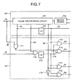
- Fig. 7 is a circuit schematic of the waveform generating unit 651 and the control-signal generating unit 107 of the electronic timepiece according to the embodiment of the present invention.
- the waveform-shaping output signal Sb is fed to the second AND gate 715 via the first NAND gate 711 constituted of the CMOS with a low threshold.
- the control-signal generating unit 107 generates a boosting clock Sa, and outputs the same to the boosting unit 103 (step S1104).
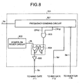
- a frequency-dividing circuit 1801 shown in Fig. 18 is a counter circuit constituted of a flip-flop train of 15 stages or more like the frequency-dividing circuit 801 shown in Fig. 8 .
- the frequency-dividing circuit 1801 frequency-divides a waveform-shaping output signal Sb outputted from the waveform shaping unit 603 shown in Fig. 6 , and outputs the same to the motor driver 702.
- the inputted time information is written to the EEPROM 2005.
- the EEPROM 2005 can be constituted of 2 bits or so.
- a flash memory may be used instead of the EEPROM 2005.
- the output I/F 2006 outputs a boosting stop instruction signal generated to the latch circuit 1805 shown in Fig. 18 .
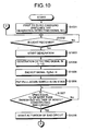
- FIG. 22 is a flowchart of a boosting-stop-instruction-signal output processing procedure of the boosting-stop-instruction-signal output unit 2000.
- thermocouple even if a small-sized solar battery, thermocouple, or rotary weight where a generated voltage is a power source voltage or so is mounted, actuation can be made sufficiently. Therefore, the present invention can be also applied to an electronic timepiece for a woman smaller than an electronic timepiece for a man. Since it is unnecessary to provide a large-sized solar battery, thermocouple, or rotary weight that generates an activation voltage, a small-sized electronic timepiece for a woman with a fine decoration can be generated.
Landscapes
- Engineering & Computer Science (AREA)
- Power Engineering (AREA)
- Physics & Mathematics (AREA)
- General Physics & Mathematics (AREA)
- Electric Clocks (AREA)
- Electromechanical Clocks (AREA)
- Dc-Dc Converters (AREA)
- Oscillators With Electromechanical Resonators (AREA)
Claims (12)
- Elektronische Uhr, umfassend:eine Energiequellespannungserzeugungseinheit (101), welche konfiguriert ist, um externe Energie in elektrische Energie zu konvertieren, um eine Energiequellenspannung niedriger als eine vorbestimmte Betriebsspannung zu erzeugen;eine Oszillationssignalausgabeeinheit (601), welche konfiguriert ist, um ein vorbestimmtes Oszillationssignal auszugeben, wenn die Energiequellenspannung, welche durch die energiequellenspannungserzeugende Einheit (101) erzeugt wird, an die Oszillationssignalausgabeeinheit (601) angelegt wird;eine Verstärkungseinheit (103), welche konfiguriert ist, um die Energiequellenspannung, welche durch die Energiequellenspannungserzeugungseinheit (101) erzeugt wird, auf zumindest die vorbestimmte Betriebsspannung zu verstärken;gekennzeichnet durcheine Verstärkungssteuereinheit (105), welche konfiguriert ist, um die Verstärkungseinheit (103) zu steuern, um die Energiequellenspannung nur für eine vorbestimmte Zeit zu verstärken, nachdem die Oszillationssignalausgabeeinheit (601) zu arbeiten begonnen hat, basierend auf dem vorbestimmten Oszillationssignal; undeine Zeitgabeeinheit (605), welche konfiguriert ist, um zu takten, wenn die vorbestimmte Betriebsspannung, welche durch die Verstärkungssteuereinheit (105) verstärkt wird, an die Zeitgabeeinheit (605) angelegt wird, basierend auf dem vorbestimmten Oszillationssignal.
- Elektronische Uhr gemäß Anspruch 1, weiterhin umfassend
eine frequenzteilende Einheit (801), welche konfiguriert ist, das vorbestimmte Oszillationssignal frequenzzuteilen, und ein frequenzteilendes Signal auszugeben; und eine Verstärkungs-Stopp-Instruktions-Signalausgabeeinheit (2000), welche konfiguriert ist, um ein Verstärkungs-Stopp-Instruktions-Signal auszugeben zum Stoppen eines Verstärkungsverhaltens, welches durch die Verstärkungseinheit (103) durchgeführt wird, basierend auf dem frequenzteilenden Signal, wenn die vorbestimmte Zeit abläuft, nachdem die Oszillationssignalausgabeeinheit (601) das Oszillationssignal ausgibt, wobei
die Verstärkungssteuereinheit (105) das Verstärkungsverhalten basierend auf dem Verstärkungs-Stopp-Instruktions-Signal stoppt. - Elektronische Uhr gemäß Anspruch 1, weiterhin umfassend
eine Verstärkungs-Stopp-Instruktions-Signalausgabeeinheit (2000), welche konfiguriert ist, um ein Verstärkungs-Stopp-Instruktions-Signal auszugeben zum Stoppen eines Verstärkungsverhaltens, welches durch die Verstärkungseinheit (103) durchgeführt wird, wenn die vorbestimmte Zeit abläuft, wobei
das Verstärkungsverhalten basierend auf dem Verstärkungs-Stopp-Instruktions-Signal gestoppt wird. - Elektronische Uhr gemäß Anspruch 1, weiterhin umfassend:eine Zeitinformations-Eingabeeinheit (2101), welche konfiguriert ist, um Zeitinformation einzugeben, welche eine von einer Vielzahl von vorbestimmten Zeiten repräsentiert,wobei Zeitintervalle der vorbestimmten Zeiten unterschiedlich zueinander sind;eine Zeitinformations-Speichereinheit (2103), welche konfiguriert ist, um die eingegebene Zeitinformation zu speichern;eine Zeitinformations-Extraktionseinheit (2104), welche konfiguriert ist, um die gespeicherte Zeitinformation zu extrahieren, wenn die Energiequellenspannung,welche durch die Energiequellenspannungserzeugungseinheit (101) erzeugt wird, an die Zeitinformations-Extraktionseinheit (2104) angelegt wird; undeine Verstärkungs-Stopp-Instruktions-Signal-Erzeugungseinheit (2105), welche konfiguriert ist, um ein Stopp-Instruktions-Signal zu verstärken zum Stoppen eines Verstärkungsverhaltens, welches durch die Verstärkungseinheit (103) durchgeführt wird, basierend auf der durch die Zeitinformations-Extraktionseinheit (2104) extrahierten Information, wenn eine vorbestimmte Zeit, welche durch die Zeitinformation gekennzeichnet ist, abläuft, wobeidas Verstärkungsverhalten basierend auf dem Verstärkungs-Stopp-Instruktions-Signal gestoppt wird.
- Elektronische Uhr umfassend:eine Energiequellenspannungserzeugungseinheit (101), welche konfiguriert ist, um externe Energie in elektrische Energie zu konvertieren, und um eine Energiequellenspannung niedriger als eine vorbestimmte Betriebsspannung zu erzeugen;eine Oszillationssignal-Ausgabeeinheit (601), welche konfiguriert ist, um ein vorbestimmtes Oszillationssignal auszugeben, wenn die Energiequellenspannung, welche durch die Energiequellenspannungserzeugungseinheit (101) erzeugt wird, an die Oszillationssignal-Ausgabeeinheit (601) angelegt wird;eine Verstärkungseinheit (103), welche konfiguriert ist, um die Energiequellenspannung zu verstärken, welche durch die Energiequellenspannungserzeugungseinheit (101) erzeugt wird, auf zumindest die vorbestimmte Betriebsspannung;eine Energiequellenspannungsdetektiereinheit (1501), welche konfiguriert ist, um zu detektieren, ob die Energiequellenspannung auf die vorbestimmte Betriebsspannung durch die Verstärkungseinheit (103) verstärkt ist;gekennzeichnet durch eine Verstärkungssteuereinheit (105), welche konfiguriert ist, um die Verstärkungseinheit (103) zu steuern, und um die Energiequellenspannung zu verstärken, nachdem die Oszillationssignal-Ausgabeeinheit (601) zu arbeiten begonnen hat, bis die Energiequellenspannungsdetektiereinheit die vorbestimmte Energiequellenspannung detektiert; undeine Zeitgabeeinheit (605), welche konfiguriert ist, um zu takten, wenn die vorbestimmte Betriebsspannung, welche durch die Verstärkungssteuereinheit (105) verstärkt ist, an die Zeitgabeeinheit (605) angelegt wird, basierend auf dem vorbestimmten Oszillationssignal.
- Elektronische Uhr gemäß Anspruch 5, wobei die Verstärkungssteuereinheit (105) konfiguriert ist, um das Verstärkungsverhalten zu steuern, welches durch die Verstärkungseinheit (103) durchgeführt wird, basierend auf dem vorbestimmten Oszillationssignal und dem Detektionsergebnis der Energiequellenspannungsdetektiereinheit (1501), wenn eine vorbestimmte Zeit abläuft, nachdem die Oszillationssignal-Ausgabeeinheit (601) das vorbestimmte Oszillationssignal ausgibt.
- Elektronische Uhr gemäß irgendeinem der Ansprüche 1 bis 6, wobei die Oszillationssignal-Ausgabeeinheit (601) enthält
eine Konstantstromschaltung (627), welche konfiguriert ist, um einen konstanten Strom zuzuführen;
einen Oszillationsinverter (620), welcher konfiguriert ist, um eine Eingabe an den Oszillationsinverter (620) umzukehren und zu verstärken, und um das vorbestimmte Oszillationssignal auszugeben, wenn die Konstantstromschaltung (627) einen konstanten Strom zu dem Oszillationsinverter (620) zuführt, wobei der Oszillationsinverter (620) ein Eingangsterminal und ein Ausgangsterminal aufweist; eine Resonanzschaltung (610), welche zwischen dem Eingangsterminal des Oszillationsinverters (620) und dem Ausgangsterminal des Oszillationsinverters (620) angeschlossen ist und konfiguriert ist, um zu schwingen. - Elektronische Uhr gemäß Anspruch 7, wobei
die Zeitgabeeinheit (605) eine Logikschaltung enthält, welche eine Vielzahl von Feldeffekttransistoren aufweist, und
der Oszillationsinverter (620) einen Feldeffekttransistor (621, 622) enthält, welcher eine Schwellenspannung niedriger als eine Schwellenspannung von jedem von den Feldeffekttransistoren der Zeitgabeeinheit (605) aufweist. - Elektronische Uhr gemäß Anspruch 7, wobei
die Zeitgabeeinheit (605) eine Logikschaltung enthält, welche eine Vielzahl von Feldeffekttransistoren aufweist, und
die elektronische Uhr weiterhin eine Wellenformformungseinheit (603) umfasst, welche einen Feldeffekttransistor (631, 632) enthält, welcher eine Schwellenspannung niedriger als eine vorbestimmte Spannung von jedem von den Feldeffekttransistoren der Zeitgabeeinheit (605) aufweist, und welcher konfiguriert ist, um eine Wellenform des Oszillationssignals zu formen, welches von der Oszillationssignalausgabeeinheit (601) ausgegeben wird, und um ein Oszillationssignal auszugeben, welches die Wellenform aufweist, welche durch die Zeitgabeeinheit (605) geformt ist. - Elektronische Uhr gemäß Anspruch 7, wobei
die Zeitgabeeinheit (605) eine Logikschaltung enthält, welche eine Vielzahl von Feldeffekttransistoren aufweist, und
die Verstärkungssteuereinheit (105) einen Feldeffekttransistor enthält, welcher eine Schwellenspannung niedriger als eine Schwellenspannung von jedem der Feldeffekttransistoren der Zeitgabeeinheit (605) aufweist. - Elektronische Uhr gemäß Anspruch 7, weiterhin umfassend eine Vorspannungsschaltung (604), welche einen Feldeffekttransistor (641, 642, 643, 644) enthält, welcher einen Schwellenwert aufweist, welcher gleich wie ein Schwellenwert des Oszillationsinverters (620) ist, und konfiguriert ist, um eine vorbestimmte Vorspannungsspannung an den Oszillationsinverter (620) anzulegen.
- Elektronische Uhr gemäß Anspruch 7, weiterhin umfassend
eine Wellenformformungseinheit (603), welche konfiguriert ist, um eine Wellenform des Oszillationssignals zu formen, welche von der Oszillationssignal-Ausgabeeinheit (601) ausgegeben wird, und um eine Oszillationssignal auszugeben, welches die Wellenform aufweist, welche durch die Zeitgabeeinheit (605) geformt ist, und
eine Vorspannungsschaltung (604), welche einen Feldeffekttransistor (641, 642, 643, 644) enthält, welcher einen Schwellenwert aufweist, welcher gleich ist wie ein Schwellenwert der Wellenformformungseinheit (603), und welcher konfiguriert ist, um eine vorbestimmte Vorspannungsspannung an die Wellenformformungseinheit (603) anzulegen.
Applications Claiming Priority (3)
| Application Number | Priority Date | Filing Date | Title |
|---|---|---|---|
| JP2002276572 | 2002-09-24 | ||
| JP2002276572 | 2002-09-24 | ||
| PCT/JP2003/012145 WO2004029735A1 (ja) | 2002-09-24 | 2003-09-24 | 電子時計、電子機器および起動方法 |
Publications (3)
| Publication Number | Publication Date |
|---|---|
| EP1544694A1 EP1544694A1 (de) | 2005-06-22 |
| EP1544694A4 EP1544694A4 (de) | 2008-06-18 |
| EP1544694B1 true EP1544694B1 (de) | 2012-04-04 |
Family
ID=32040385
Family Applications (1)
| Application Number | Title | Priority Date | Filing Date |
|---|---|---|---|
| EP03748571A Expired - Lifetime EP1544694B1 (de) | 2002-09-24 | 2003-09-24 | Elektronische uhr |
Country Status (5)
| Country | Link |
|---|---|
| US (1) | US7327638B2 (de) |
| EP (1) | EP1544694B1 (de) |
| JP (1) | JP4459812B2 (de) |
| CN (1) | CN100422879C (de) |
| WO (1) | WO2004029735A1 (de) |
Families Citing this family (15)
| Publication number | Priority date | Publication date | Assignee | Title |
|---|---|---|---|---|
| US7474249B1 (en) * | 2004-08-12 | 2009-01-06 | Lockheed Martin Corporation | Systems and methods for dedicating power to a radar module |
| JP5211534B2 (ja) * | 2007-04-03 | 2013-06-12 | セイコーエプソン株式会社 | 発電機能付き電子時計 |
| WO2010011118A1 (es) * | 2008-07-21 | 2010-01-28 | Garcia De Alba Garcin Sergio | Un convertidor boost auto-oscilatorio para aplicaciones solares |
| US8754549B2 (en) | 2008-07-24 | 2014-06-17 | Mitsubishi Electric Corporation | Power conversion device |
| JP2011147330A (ja) * | 2009-12-16 | 2011-07-28 | Seiko Instruments Inc | ステッピングモータ制御回路及びアナログ電子時計 |
| JP5823747B2 (ja) * | 2010-09-03 | 2015-11-25 | セイコーインスツル株式会社 | 消費電力制御装置、時計装置、電子機器、消費電力制御方法、及び消費電力制御プログラム |
| KR20150019000A (ko) * | 2013-08-12 | 2015-02-25 | 삼성디스플레이 주식회사 | 기준 전류 생성 회로 및 이의 구동 방법 |
| CN104467810B (zh) * | 2014-12-05 | 2018-07-13 | 无锡中感微电子股份有限公司 | 一种数字整形方法和采用该方法的时钟系统 |
| US10171033B2 (en) * | 2016-11-03 | 2019-01-01 | Intel Corporation | Crystal oscillator interconnect architecture with noise immunity |
| DE102017204044A1 (de) * | 2017-02-14 | 2018-08-16 | Ellenberger & Poensgen Gmbh | Verfahren und Spannungsvervielfacher zur Wandlung einer Eingangsspannung sowie Trennschaltung |
| JP6658610B2 (ja) * | 2017-02-27 | 2020-03-04 | カシオ計算機株式会社 | 情報通知方法、情報通知装置、及びプログラム |
| JP7200512B2 (ja) * | 2018-06-21 | 2023-01-10 | カシオ計算機株式会社 | 電子機器、電子時計および電池充電方法 |
| JP7256102B2 (ja) * | 2019-10-21 | 2023-04-11 | ルネサスエレクトロニクス株式会社 | 電子システム装置、及び電子システム装置の起動方法 |
| CN117394795A (zh) * | 2023-10-26 | 2024-01-12 | 杭州朔天科技有限公司 | 晶体振荡器电路的负电容电路、控制方法及微处理芯片 |
| CN118677444B (zh) * | 2024-08-23 | 2025-02-25 | 深圳市华普微电子股份有限公司 | 一种快速启动的晶体振荡电路 |
Family Cites Families (21)
| Publication number | Priority date | Publication date | Assignee | Title |
|---|---|---|---|---|
| JPS5240371A (en) * | 1975-09-27 | 1977-03-29 | Citizen Watch Co Ltd | Electronic watch |
| JPS54123068A (en) * | 1978-03-17 | 1979-09-25 | Citizen Watch Co Ltd | Electronic watch |
| JPS5625280U (de) | 1980-07-16 | 1981-03-07 | ||
| JPS5745483A (en) | 1980-09-02 | 1982-03-15 | Citizen Watch Co Ltd | Circuit for electrooptic display timepiece |
| GB2149942B (en) * | 1983-11-21 | 1987-03-04 | Shiojiri Kogyo Kk | Electronic timepiece |
| JPH0792507B2 (ja) | 1985-03-29 | 1995-10-09 | セイコーエプソン株式会社 | 電子時計 |
| JP2622540B2 (ja) * | 1985-04-10 | 1997-06-18 | セイコーエプソン株式会社 | 電子時計 |
| JPH078108B2 (ja) | 1985-06-03 | 1995-01-30 | カシオ計算機株式会社 | 電源供給方式 |
| JP2973273B2 (ja) * | 1994-05-13 | 1999-11-08 | セイコーエプソン株式会社 | 電子時計及びその充電方法 |
| JP3174245B2 (ja) * | 1994-08-03 | 2001-06-11 | セイコーインスツルメンツ株式会社 | 電子制御時計 |
| JPH0996686A (ja) | 1995-09-29 | 1997-04-08 | Citizen Watch Co Ltd | 電子時計とその充電方法 |
| CH691010A5 (fr) * | 1997-01-09 | 2001-03-30 | Asulab Sa | Appareil électrique fonctionnant à l'aide d'une source photovoltaïque, notamment pièce d'horlogerie. |
| US6122185A (en) | 1997-07-22 | 2000-09-19 | Seiko Instruments R&D Center Inc. | Electronic apparatus |
| JP3650269B2 (ja) * | 1997-10-07 | 2005-05-18 | セイコーインスツル株式会社 | 発電素子を有する電子時計 |
| US6301198B1 (en) * | 1997-12-11 | 2001-10-09 | Citizen Watch Co., Ltd. | Electronic timepiece |
| JP2000125578A (ja) | 1998-07-02 | 2000-04-28 | Citizen Watch Co Ltd | 熱電システム |
| US6466519B1 (en) * | 1998-12-04 | 2002-10-15 | Seiko Epson Corporation | Electronic device, electronic timepiece and power control method |
| JP3596383B2 (ja) * | 1999-11-04 | 2004-12-02 | セイコーエプソン株式会社 | 発電機を持つ電子時計の充電装置、電子時計、及び充電装置の制御方法 |
| JP2002280834A (ja) | 2001-03-16 | 2002-09-27 | Citizen Watch Co Ltd | 発振回路およびそれを用いた電子時計 |
| JP4963764B2 (ja) | 2001-09-11 | 2012-06-27 | シチズンホールディングス株式会社 | 電子時計 |
| US10391545B2 (en) * | 2017-03-17 | 2019-08-27 | The Boeing Company | Self-aligning riveting method |
-
2003
- 2003-09-24 US US10/528,807 patent/US7327638B2/en not_active Expired - Lifetime
- 2003-09-24 CN CNB038253631A patent/CN100422879C/zh not_active Expired - Lifetime
- 2003-09-24 WO PCT/JP2003/012145 patent/WO2004029735A1/ja not_active Ceased
- 2003-09-24 EP EP03748571A patent/EP1544694B1/de not_active Expired - Lifetime
- 2003-09-24 JP JP2004539497A patent/JP4459812B2/ja not_active Expired - Lifetime
Also Published As
| Publication number | Publication date |
|---|---|
| US7327638B2 (en) | 2008-02-05 |
| EP1544694A1 (de) | 2005-06-22 |
| JP4459812B2 (ja) | 2010-04-28 |
| JPWO2004029735A1 (ja) | 2006-01-26 |
| WO2004029735A1 (ja) | 2004-04-08 |
| CN1701284A (zh) | 2005-11-23 |
| US20050243657A1 (en) | 2005-11-03 |
| CN100422879C (zh) | 2008-10-01 |
| EP1544694A4 (de) | 2008-06-18 |
Similar Documents
| Publication | Publication Date | Title |
|---|---|---|
| EP1544694B1 (de) | Elektronische uhr | |
| USRE35043E (en) | Self-charging electronic timepiece | |
| US6580665B1 (en) | Electronic timepiece having power generating function | |
| WO1999030212A1 (en) | Electronic timepiece | |
| JP4652491B2 (ja) | 光電源で給電される電気装置、特に時計 | |
| US4763310A (en) | Electronic clock with solar cell and rechangeable battery | |
| JP3515958B2 (ja) | 電子時計 | |
| CN1099150C (zh) | 包含利用光生伏打电池为蓄电池充电的充电装置的钟表 | |
| JP3830289B2 (ja) | 電子機器および計時装置 | |
| JP3601375B2 (ja) | 携帯用電子機器及び携帯用電子機器の制御方法 | |
| JPWO2000023853A1 (ja) | 電子時計 | |
| WO1998035272A1 (en) | Electronic clock | |
| JP6610048B2 (ja) | 半導体装置および電子時計 | |
| JP4647806B2 (ja) | 昇圧システム | |
| JP4963764B2 (ja) | 電子時計 | |
| JP4349388B2 (ja) | 電子機器、電子機器の制御方法、計時装置、および計時装置の制御方法 | |
| JP4055446B2 (ja) | 電子機器、電子機器の制御方法、計時装置、および計時装置の制御方法 | |
| JP2004279300A (ja) | 電子時計 | |
| JP3632495B2 (ja) | 電子機器および電子機器の制御方法 | |
| JP3906720B2 (ja) | 携帯用電子機器及び携帯用電子機器の制御方法 | |
| JP3017541B2 (ja) | 電子時計 | |
| JP2002250782A (ja) | 発電機構付き電子時計 | |
| JPWO2000060419A1 (ja) | 電子機器および電子機器の制御方法 | |
| JPH0450550B2 (de) | ||
| JPH01114333A (ja) | 電源回路 |
Legal Events
| Date | Code | Title | Description |
|---|---|---|---|
| PUAI | Public reference made under article 153(3) epc to a published international application that has entered the european phase |
Free format text: ORIGINAL CODE: 0009012 |
|
| 17P | Request for examination filed |
Effective date: 20050322 |
|
| AK | Designated contracting states |
Kind code of ref document: A1 Designated state(s): AT BE BG CH CY CZ DE DK EE ES FI FR GB GR HU IE IT LI LU MC NL PT RO SE SI SK TR |
|
| RBV | Designated contracting states (corrected) |
Designated state(s): DE IT |
|
| RAP1 | Party data changed (applicant data changed or rights of an application transferred) |
Owner name: CITIZEN HOLDINGS CO., LTD. |
|
| A4 | Supplementary search report drawn up and despatched |
Effective date: 20080521 |
|
| 17Q | First examination report despatched |
Effective date: 20100202 |
|
| REG | Reference to a national code |
Ref country code: DE Ref legal event code: R079 Ref document number: 60340493 Country of ref document: DE Free format text: PREVIOUS MAIN CLASS: G04G0001000000 Ipc: G04C0010020000 |
|
| GRAP | Despatch of communication of intention to grant a patent |
Free format text: ORIGINAL CODE: EPIDOSNIGR1 |
|
| RIC1 | Information provided on ipc code assigned before grant |
Ipc: G04F 5/06 20060101ALI20111020BHEP Ipc: G04C 10/02 20060101AFI20111020BHEP Ipc: G04G 19/04 20060101ALI20111020BHEP |
|
| RTI1 | Title (correction) |
Free format text: ELECTRONIC TIMEPIECE |
|
| RIN1 | Information on inventor provided before grant (corrected) |
Inventor name: NAGATA, YOICHI |
|
| GRAS | Grant fee paid |
Free format text: ORIGINAL CODE: EPIDOSNIGR3 |
|
| GRAA | (expected) grant |
Free format text: ORIGINAL CODE: 0009210 |
|
| AK | Designated contracting states |
Kind code of ref document: B1 Designated state(s): DE IT |
|
| REG | Reference to a national code |
Ref country code: DE Ref legal event code: R081 Ref document number: 60340493 Country of ref document: DE Owner name: CITIZEN WATCH CO., LTD., NISHITOKYO-SHI, JP Free format text: FORMER OWNER: CITIZEN WATCH CO., LTD., NISHITOKYO, TOKIO/TOKYO, JP |
|
| REG | Reference to a national code |
Ref country code: DE Ref legal event code: R096 Ref document number: 60340493 Country of ref document: DE Effective date: 20120531 |
|
| PLBE | No opposition filed within time limit |
Free format text: ORIGINAL CODE: 0009261 |
|
| STAA | Information on the status of an ep patent application or granted ep patent |
Free format text: STATUS: NO OPPOSITION FILED WITHIN TIME LIMIT |
|
| 26N | No opposition filed |
Effective date: 20130107 |
|
| REG | Reference to a national code |
Ref country code: DE Ref legal event code: R097 Ref document number: 60340493 Country of ref document: DE Effective date: 20130107 |
|
| REG | Reference to a national code |
Ref country code: DE Ref legal event code: R082 Ref document number: 60340493 Country of ref document: DE Representative=s name: MITSCHERLICH, PATENT- UND RECHTSANWAELTE PARTM, DE Ref country code: DE Ref legal event code: R081 Ref document number: 60340493 Country of ref document: DE Owner name: CITIZEN WATCH CO., LTD., NISHITOKYO-SHI, JP Free format text: FORMER OWNER: CITIZEN HOLDINGS CO., LTD., TOKYO, JP |
|
| PGFP | Annual fee paid to national office [announced via postgrant information from national office to epo] |
Ref country code: DE Payment date: 20190910 Year of fee payment: 17 |
|
| REG | Reference to a national code |
Ref country code: DE Ref legal event code: R119 Ref document number: 60340493 Country of ref document: DE |
|
| PG25 | Lapsed in a contracting state [announced via postgrant information from national office to epo] |
Ref country code: DE Free format text: LAPSE BECAUSE OF NON-PAYMENT OF DUE FEES Effective date: 20210401 |
|
| PGFP | Annual fee paid to national office [announced via postgrant information from national office to epo] |
Ref country code: IT Payment date: 20220811 Year of fee payment: 20 |