EP1544652A1 - Objektivlinse f r eine optische bilderfassungseinrichtung, optische bilderfassungseinrichtung und optische informationsaufzeichnungs-/-wiedergabeeinrichtung - Google Patents
Objektivlinse f r eine optische bilderfassungseinrichtung, optische bilderfassungseinrichtung und optische informationsaufzeichnungs-/-wiedergabeeinrichtung Download PDFInfo
- Publication number
- EP1544652A1 EP1544652A1 EP03791401A EP03791401A EP1544652A1 EP 1544652 A1 EP1544652 A1 EP 1544652A1 EP 03791401 A EP03791401 A EP 03791401A EP 03791401 A EP03791401 A EP 03791401A EP 1544652 A1 EP1544652 A1 EP 1544652A1
- Authority
- EP
- European Patent Office
- Prior art keywords
- objective lens
- optical
- information recording
- pickup device
- wavelength
- Prior art date
- Legal status (The legal status is an assumption and is not a legal conclusion. Google has not performed a legal analysis and makes no representation as to the accuracy of the status listed.)
- Withdrawn
Links
- 230000003287 optical effect Effects 0.000 title claims abstract description 592
- 230000004075 alteration Effects 0.000 claims abstract description 213
- 230000000694 effects Effects 0.000 claims description 134
- 238000013461 design Methods 0.000 claims description 76
- 230000007613 environmental effect Effects 0.000 claims description 42
- 230000015572 biosynthetic process Effects 0.000 claims description 36
- 230000002093 peripheral effect Effects 0.000 claims description 12
- 230000008859 change Effects 0.000 description 41
- 235000005811 Viola adunca Nutrition 0.000 description 21
- 240000009038 Viola odorata Species 0.000 description 21
- 235000013487 Viola odorata Nutrition 0.000 description 21
- 235000002254 Viola papilionacea Nutrition 0.000 description 21
- 238000012937 correction Methods 0.000 description 15
- 238000004519 manufacturing process Methods 0.000 description 13
- 239000010410 layer Substances 0.000 description 8
- 230000001681 protective effect Effects 0.000 description 8
- 206010010071 Coma Diseases 0.000 description 7
- 230000001105 regulatory effect Effects 0.000 description 6
- NAWXUBYGYWOOIX-SFHVURJKSA-N (2s)-2-[[4-[2-(2,4-diaminoquinazolin-6-yl)ethyl]benzoyl]amino]-4-methylidenepentanedioic acid Chemical compound C1=CC2=NC(N)=NC(N)=C2C=C1CCC1=CC=C(C(=O)N[C@@H](CC(=C)C(O)=O)C(O)=O)C=C1 NAWXUBYGYWOOIX-SFHVURJKSA-N 0.000 description 5
- 230000010287 polarization Effects 0.000 description 5
- 230000009467 reduction Effects 0.000 description 5
- 230000000630 rising effect Effects 0.000 description 5
- 230000007423 decrease Effects 0.000 description 4
- 238000005259 measurement Methods 0.000 description 4
- 239000011241 protective layer Substances 0.000 description 4
- 230000008901 benefit Effects 0.000 description 3
- 102000011842 Serrate-Jagged Proteins Human genes 0.000 description 2
- 108010036039 Serrate-Jagged Proteins Proteins 0.000 description 2
- 230000015556 catabolic process Effects 0.000 description 2
- 238000006731 degradation reaction Methods 0.000 description 2
- 239000006185 dispersion Substances 0.000 description 2
- 230000002349 favourable effect Effects 0.000 description 2
- 239000011521 glass Substances 0.000 description 2
- 239000000463 material Substances 0.000 description 2
- 238000000034 method Methods 0.000 description 2
- 238000000465 moulding Methods 0.000 description 2
- 230000008569 process Effects 0.000 description 2
- 238000011161 development Methods 0.000 description 1
- 238000001746 injection moulding Methods 0.000 description 1
- 230000007246 mechanism Effects 0.000 description 1
- 239000000758 substrate Substances 0.000 description 1
Images


Classifications
-
- G—PHYSICS
- G11—INFORMATION STORAGE
- G11B—INFORMATION STORAGE BASED ON RELATIVE MOVEMENT BETWEEN RECORD CARRIER AND TRANSDUCER
- G11B7/00—Recording or reproducing by optical means, e.g. recording using a thermal beam of optical radiation by modifying optical properties or the physical structure, reproducing using an optical beam at lower power by sensing optical properties; Record carriers therefor
- G11B7/12—Heads, e.g. forming of the optical beam spot or modulation of the optical beam
- G11B7/135—Means for guiding the beam from the source to the record carrier or from the record carrier to the detector
- G11B7/1353—Diffractive elements, e.g. holograms or gratings
-
- G—PHYSICS
- G11—INFORMATION STORAGE
- G11B—INFORMATION STORAGE BASED ON RELATIVE MOVEMENT BETWEEN RECORD CARRIER AND TRANSDUCER
- G11B7/00—Recording or reproducing by optical means, e.g. recording using a thermal beam of optical radiation by modifying optical properties or the physical structure, reproducing using an optical beam at lower power by sensing optical properties; Record carriers therefor
- G11B7/12—Heads, e.g. forming of the optical beam spot or modulation of the optical beam
- G11B7/135—Means for guiding the beam from the source to the record carrier or from the record carrier to the detector
- G11B7/1372—Lenses
- G11B7/1374—Objective lenses
-
- G—PHYSICS
- G02—OPTICS
- G02B—OPTICAL ELEMENTS, SYSTEMS OR APPARATUS
- G02B13/00—Optical objectives specially designed for the purposes specified below
-
- G—PHYSICS
- G02—OPTICS
- G02B—OPTICAL ELEMENTS, SYSTEMS OR APPARATUS
- G02B27/00—Optical systems or apparatus not provided for by any of the groups G02B1/00 - G02B26/00, G02B30/00
- G02B27/0025—Optical systems or apparatus not provided for by any of the groups G02B1/00 - G02B26/00, G02B30/00 for optical correction, e.g. distorsion, aberration
- G02B27/0037—Optical systems or apparatus not provided for by any of the groups G02B1/00 - G02B26/00, G02B30/00 for optical correction, e.g. distorsion, aberration with diffracting elements
-
- G—PHYSICS
- G02—OPTICS
- G02B—OPTICAL ELEMENTS, SYSTEMS OR APPARATUS
- G02B27/00—Optical systems or apparatus not provided for by any of the groups G02B1/00 - G02B26/00, G02B30/00
- G02B27/42—Diffraction optics, i.e. systems including a diffractive element being designed for providing a diffractive effect
- G02B27/4233—Diffraction optics, i.e. systems including a diffractive element being designed for providing a diffractive effect having a diffractive element [DOE] contributing to a non-imaging application
- G02B27/4238—Diffraction optics, i.e. systems including a diffractive element being designed for providing a diffractive effect having a diffractive element [DOE] contributing to a non-imaging application in optical recording or readout devices
-
- G—PHYSICS
- G02—OPTICS
- G02B—OPTICAL ELEMENTS, SYSTEMS OR APPARATUS
- G02B27/00—Optical systems or apparatus not provided for by any of the groups G02B1/00 - G02B26/00, G02B30/00
- G02B27/42—Diffraction optics, i.e. systems including a diffractive element being designed for providing a diffractive effect
- G02B27/4283—Diffraction optics, i.e. systems including a diffractive element being designed for providing a diffractive effect having a diffractive element with major temperature dependent properties
-
- G—PHYSICS
- G02—OPTICS
- G02B—OPTICAL ELEMENTS, SYSTEMS OR APPARATUS
- G02B5/00—Optical elements other than lenses
- G02B5/18—Diffraction gratings
- G02B5/1876—Diffractive Fresnel lenses; Zone plates; Kinoforms
- G02B5/189—Structurally combined with optical elements not having diffractive power
- G02B5/1895—Structurally combined with optical elements not having diffractive power such optical elements having dioptric power
-
- G—PHYSICS
- G11—INFORMATION STORAGE
- G11B—INFORMATION STORAGE BASED ON RELATIVE MOVEMENT BETWEEN RECORD CARRIER AND TRANSDUCER
- G11B7/00—Recording or reproducing by optical means, e.g. recording using a thermal beam of optical radiation by modifying optical properties or the physical structure, reproducing using an optical beam at lower power by sensing optical properties; Record carriers therefor
- G11B7/12—Heads, e.g. forming of the optical beam spot or modulation of the optical beam
- G11B7/135—Means for guiding the beam from the source to the record carrier or from the record carrier to the detector
- G11B7/1392—Means for controlling the beam wavefront, e.g. for correction of aberration
-
- G—PHYSICS
- G02—OPTICS
- G02B—OPTICAL ELEMENTS, SYSTEMS OR APPARATUS
- G02B27/00—Optical systems or apparatus not provided for by any of the groups G02B1/00 - G02B26/00, G02B30/00
- G02B27/42—Diffraction optics, i.e. systems including a diffractive element being designed for providing a diffractive effect
- G02B27/4294—Diffraction optics, i.e. systems including a diffractive element being designed for providing a diffractive effect in multispectral systems, e.g. UV and visible
Definitions
- the present invention relates to an optical pickup device, an optical information recording/reproducing apparatus and an objective lens used for them, and particularly, relates to an optical pickup device, an optical information recording/reproducing apparatus which are capable of high density optical information recording or reproducing, and an objective lens used for them.
- a plastic single lens has been generally used as an objective lens used in an optical pickup device or optical information recording/reproducing apparatus for recording or reproducing an optical information recording medium such as a CD, MD and DVD.
- a plastic lens Because of lower specific density than a glass lens, a plastic lens has an advantage that it is possible to reduce the burden of an actuator driving the objective lens for focusing and tracking, and to perform tracking of the objective lens in this regard at high speed.
- a plastic lens produced by injection molding in a mold can be mass-produced by manufacturing a desired mold with high accuracy. Thereby, although it is made possible to exert high performance of the lens stably, it is made possible to plan to reduce the cost.
- high-density DVD an optical disk performing information recording/reproducing with descriptions of an NA of 0.85 and a light source wavelength of 405 nm
- thermo aberration spherical aberration generated by refractive index change accompanying temperature change
- thermal aberration becomes a problem in case that an objective lens having a high NA is a plastic lens.
- thermal aberration occurs owing to a plastic lens two orders of magnitude larger than a glass lens in terms of change of the refractive index.
- Usable temperature range becomes very narrow in case that the objective lens having an NA of 0.85 used for a high-density DVD is a plastic lens because the thermal aberration is proportional to 4th power of the NA, and accordingly it becomes a problem in practical use.
- JP Tokukaihei-11-337818A an art of correcting such thermal aberration of a plastic single lens by using the diffraction effect of a ring-shaped phase structure formed on its optical surface is described.
- chromatic spherical aberration For correcting thermal aberration of a plastic lens having an NA of 0.85 by this art, it is necessary to set a tilt of a spherical aberration curve in change of wavelength (hereinafter, such tilt of a spherical aberration curve is referred to as "chromatic spherical aberration") large. Therefore, it is impossible to use a laser diode having an emission wavelength that deviates from a standard wavelength by a manufacturing error, and selection of laser diodes becomes necessary, which causes a high cost.
- An objective lens whose lens data is shown in Table 1 is a plastic single lens having an incident light beam diameter of 3 mm, a focal length of 2.5 mm, an NA of 0.6, a design wavelength of 650 nm and a design temperature of 25 °C, and corrects thermal aberration by the diffraction effect of a ring-shaped phase structure formed on the first surface (optical surface of a light source example).
- an objective lens whose lens data is shown in Table 2 is a plastic single lens having an incident light beam diameter of 3 mm, a focal length of 1.76 mm, an NA of 0.85, a design wavelength of 405 nm and a design temperature of 25 °C, and corrects thermal aberration by the diffraction effect of a ring-shaped phase structure formed on the first surface in the same way as the objective lens of Table 1.
- a power-of-ten number e.g. 2.5 ⁇ 10 -3
- E e.g. 2.5 ⁇ E-3 hereinafter (including lens data in Tables).
- An aspherical surface in such an objective lens is expressed by the following Formula 1 when the optical axis direction is x-axis, the height of the direction perpendicular to the optical axis is h and the curvature radius of the optical surface is r. Note that ⁇ is a constant of the cone and A 2i is an aspherical surface coefficient.
- the ring-shaped phase structure as a diffractive structure formed on the optical surface is expressed by an optical path difference added to a transmitted wave front by the diffractive structure.
- the optical path difference is expressed by the optical path difference function ⁇ b (mm) defined by the following Formula 2, when the height of the direction perpendicular to the optical axis is h and b 2i are the diffractive surface coefficients (also referred to as optical path difference function coefficients).
- a ring surface is formed each time a value of the optical path difference function ⁇ b (mm) is changed by n-times a predetermined wavelength ⁇ B (n is only a natural number).
- n is only a natural number.
- the diffraction structure is optimized at a wavelength ⁇ B and a diffraction order n indicates that a diffraction structure is determined in this way, and the wavelength is referred to as an optimized wavelength or production wavelength.
- Table 3 shows RMS values of thermal aberration when an ambient temperature of the two objective lens has risen by 30 °C, and RMS values of chromatic spherical aberration when incident wavelength becomes 5 nm longer than the design wavelength.
- Thermal aberration (+30 °C) Chromatic spherical aberration(+5 nm) NA0.6 0. 010 ⁇ rms 0. 003 ⁇ rms NA0. 85 0. 014 ⁇ rms 0. 057 ⁇ rms
- an objective lens having an NA of 0.6 has a chromatic spherical aberration suppressed at 0.003 ⁇ rms even when the thermal aberration is corrected to 0.010 ⁇ rms, and accordingly a laser diode having a wavelength deviating by 5 nm may be used.
- the chromatic spherical aberration becomes 0.057 ⁇ rms when the thermal aberration is corrected to 0.014 ⁇ rms as much as the objective lens having an NA of 0.6, and accordingly a laser diode having a wavelength deviating by 5 nm cannot be used.
- Laser diodes used as a light source in an optical pickup device have variation of about ⁇ 5 nm in its emission wavelength, and accordingly, selection of laser diodes becomes necessary and the production cost of the optical pickup device rises in case of the objective lens having an NA of 0.85.
- both of the change rates of the refractive indexes accompanying the temperature rise are made -9.0 ⁇ 10 -5 and the change rates of the wavelength of incident light accompanying the temperature rise are respectively made +0.2 nm/°C and +0.05 nm/°C.
- r (mm) denotes a curvature radius
- d (mm) denotes a surface distance
- N650 denotes a refractive index at a wavelength of 650 nm
- vd denotes an Abbe number at the d-line
- r (mm) denotes a curvature radius
- d (mm) denotes a surface distance
- N405 denotes a refractive index at a wavelength of 405 nm
- vd denotes an Abbe number at the d-line.
- chromatic aberration generated in an objective lens becomes a problem in case of using a blue-violet laser diode generating light with a short wavelength of about 400 nm as a light source like such an optical pickup device for a high-density DVD.
- chromatic aberration of the objective lens is considered not to be a problem because laser light emitted from a laser diode has a single wavelength (single mode).
- mode hopping that a center wavelength is instantly changed by several nm owing to temperature change, output change or the like, is caused.
- the mode hopping is a wavelength change caused instantly which a focusing mechanism cannot track, there is caused a problem that a defocus component corresponding to movement of the image formation position is added and the converging ability of the objective lens is degraded when longitudinal chromatic aberration of the objective lens is corrected.
- the present invention which has been made in consideration of circumstances as described above, aims at providing a plastic single lens that is applicable as an objective lens of an optical pickup device using an objective lens having a high NA and has an available temperature range being sufficiently wide and slight degradation of converging ability owing to mode hopping of a light source.
- the present invention aims at providing a plastic single lens that is applicable as an objective lens of an optical pickup device using an objective lens having a high NA, wherein it is possible to make selection of laser diode light source unnecessary in the production step of an optical pickup device without excessive increase of chromatic spherical aberration even when thermal aberration has been corrected in order to extend the available temperature range.
- the present invention aims at providing an optical pickup device where a plastic single lens of these is mounted, and an optical information recording/reproducing apparatus where the optical pickup device is mounted.
- An objective lens for an optical pickup device of claim 1 is an objective lens used for an optical pickup device, wherein the optical pickup device comprises: a light source; and a converging optical system including the objective lens for converging a light beam emitted from the light source to an information recording surface of an optical information recording medium, and the optical pickup device is capable of recording and/or reproducing information by converging the light beam emitted from the light source to the information recording surface of the optical information recording medium with the converging optical system, and wherein the objective lens is a plastic single lens and satisfies following formulas: NA ⁇ 0.8 1.0 > f > 0.2 where NA is an image-side numerical aperture of the objective lens, which is required for recording and/or reproducing information to the optical information recording medium and f (mm) is a focal length of the objective lens.
- thermo aberration spherical aberration owing to change of the refractive index of the plastic single lens accompanying temperature rise
- thermal aberration increases in proportion to the focal length and 4th power of the NA. Accordingly, even in cases of increasing the NA for densifying an optical information recording medium, it is made possible to comparatively suppress the thermal aberration by reducing the focal length according thereto. Therefore, as for the objective lens of claim 1, by setting the upper limit of the focal length as the formula (2), thermal aberration is prevented from increasing excessively even in case of a plastic single lens having a high NA that satisfies the formula (1). Furthermore, as for a plastic single lens of a refraction type, it is impossible to make thermal aberration zero completely. However, it is possible to suppress the thermal aberration in a temperature range of practical use of the optical pickup device into an allowable range by making the focal length not excess the upper limit of the formula (2).
- the longitudinal chromatic aberration due to mode hopping of a laser diode increases in proportion to the focal length. Accordingly, even in case of using, for example, a blue-violet laser diode as the light source, it becomes possible to suppress the longitudinal chromatic aberration comparatively when the focal length is reduced corresponding thereto. As for a single lens of a refraction type, it is impossible to make chromatic aberration zero completely.
- An objective lens for the optical pickup device of claim 4 is characterized in that, in the invention of any one of claims 1 to 3, the objective lens is an objective lens of a finite conjugate type for converging a diverging light beam emitted from the light source to the information recording surface of the optical information recording medium and satisfies a following formula: 0.8 > f > 0.2
- the objective lens of claim 4 is preferable as an objective lens for an optical pickup device of which miniaturization is required, and for example, may be used as an objective lens for an optical pickup device installed in a portable optical disk player.
- an objective lens of a finite conjugate type having an image formation magnification of m and brightness as much as an objective lens of an infinity type it is necessary to design a lens having brightness (1-m) times as much as the image-side numerical aperture of the objective lens of an infinity type.
- the sign of m becomes minus and the substantial image-side numerical aperture becomes larger than the image-side numerical aperture of the objective lens of an infinity type in case that the objective lens is a finite conjugate type that converges a diverging light beam emitted from the light source on the information recording surface of the optical information recording medium. Accordingly, the thermal aberration is made large than the objective lens of the infinity type when the objective lens of the finite conjugate type is made a plastic single lens.
- the objective lens of claim 4 by making the upper limit of the focal length further less than the formula (2) and setting it as the formula (6A), it is possible to suppress thermal aberration in an allowable range of practical use even in case of a plastic single lens of a finite conjugate type having a high NA as the NA satisfies the formula (1).
- the working distance becomes larger as compared to the objective lens of the infinity type having the same focal length. Accordingly, it is not disadvantageous from the viewpoint of securing the working distance also in case of making the upper limit of the focal length further less than the formula (2) as the objective lens of claim 4.
- An objective lens for an optical pickup device of claim 5 is characterized in that, in the invention of claim 4, m satisfies following formula when m is an image formation magnification of the objective lens: 0.2 >
- An objective lens used for an optical pickup device of claim 6 is an objective lens used for an optical pickup device, wherein the optical pickup device comprises a light source; and a converging optical system including an objective lens for converging a light beam emitted from the light source to an information recording surface of an optical information recording medium, and the optical pickup device is capable of recording and/or reproducing information by converging the light beam emitted from the light source to the information recording surface of the optical information recording medium with the converging optical system, wherein the objective lens is a plastic single lens that comprises a ring-shaped phase structure on at least one optical surface, the ring-shaped phase structure comprising a plurality of ring surfaces and formed so that adjacent ring surfaces generate a predetermined optical path difference for incident light, and satisfies following formulas: NA ⁇ 0.8 1.3 > f > 0.2 where NA is an image-side numerical aperture of the objective lens, which is required for recording and/or reproducing information for the optical information recording medium and f (mm) is a focal length of the
- the plastic objective lens in which the numerical aperture NA satisfies the formula (7) in case of correcting spherical aberration (thermal aberration) that is generated by the refractive index change accompanying temperature rise by an effect of the ring-shaped phase structure formed on the optical surface thereof, the tilt (chromatic spherical aberration) of the spherical aberration curve in change of the wavelength becomes excessively large. Accordingly, it is impossible to use a laser diode having an emission wavelength that deviates from a standard wavelength by a manufacturing error, and selection of laser diodes becomes necessary.
- the variation of spherical aberration owing to change of the refractive index of the plastic objective lens increases in proportion to the focal length and 4th power of an NA. Accordingly, even in cases of the NA increasing for densifying an optical information recording medium, it is made possible to comparatively suppress the spherical aberration owing to the refractive index change of the objective lens by reducing the focal length according thereto.
- the objective lens of claim 6 it is possible to prevent chromatic spherical aberration after correcting thermal aberration from excessively increasing, because the correction amount of thermal aberration due to the effect of the ring-shaped phase structure is suppress low by setting the upper limit of the focal length as the formula (8).
- the objective lens of the present invention secured the necessary and sufficient working distance and image height characteristics by setting the upper limit of the focal length as the formula (8).
- an objective lens indicates, in the narrow sense, a lens having the converging ability which is disposed at the position closest to the optical information recording medium to face opposite it in a state that an optical recording medium is loaded in the optical pickup device, and in the broad sense, a lens capable of being actuated with the lens at least in the optical axis direction by an actuator.
- a numerical aperture of the objective lens on the optical information recording medium side indicates the numerical aperture of the lens surface of the objective lens located closest to the optical information recording medium.
- a necessary (predetermined) numerical aperture indicates a numerical aperture regulated by the standard of respective optical information recording media or a numerical aperture of an objective lens having the diffraction limit ability capable of obtaining a spot size required for recording or reproducing information depending on the wavelength of a used light source for respective optical information recording media.
- recording of information indicates recording information on an information recording surface of an optical information recording medium like the above.
- reproducing of information indicates reproducing information recorded on an information recording surface of an optical information recording medium like the above.
- An objective lens of the present invention may be used for only recording or only reproducing, and may be used for both of recording and reproducing. It may be used for recording for a certain optical information recording medium and reproducing for another optical information recording medium, or may be used for recording or reproducing for a certain optical information recording medium and recording and reproducing for another optical information recording medium.
- reproducing here includes reading information simply.
- the ring-shaped phase structure is a diffraction structure having a function for diffracting predetermined incident light and the objective lens forms a converging wave front which is converged on the information recording surface owing to an effect obtained by combining a diffraction effect and a refraction effect, and the above-described operation is exerted effectively and thereby it is preferable.
- An objective lens for the optical pickup device of claim 8 has spherical aberration characteristics that spherical aberration changes in an undercorrected direction when a wavelength of the incident light changes to a longer wavelength in the invention of claim 7.
- a plastic single lens has a refractive index reduced by temperature rise generally, spherical aberration changes in the overcorrected direction. Meanwhile, the emission wavelength of a laser diode generally has a tendency to change in the increase direction by temperature rise. Accordingly, by providing the objective lens having the above-described spherical aberration characteristics owing to the effect of the diffraction structure, change of spherical aberration that is made overcorrection by change of the refractive index accompanying temperature rise can be counterbalanced by change of.spherical aberration that is made undercorrection by change of the emission wavelength of a laser diode due to temperature rise.
- the objective lens of the present invention has a focal length satisfying the formula (8), the correction amount of thermal aberration owing to the effect of the diffraction structure is small and chromatic spherical aberration after correcting the thermal aberration does not become large excessively.
- an optical surface (diffraction surface) on which a diffraction structure is formed is a surface given an effect for diffracting an incident light beam by providing relief for surface of an optical element, e.g. a surface of a lens, and in case that there are a region for generating diffraction and a region for not generating diffraction on the same optical surface, the region for generating diffraction.
- a diffraction structure or a diffraction pattern is the region for generating diffraction.
- a shape is formed on the optical element as substantially concentric ring surfaces centered on the optical axis, and when its section of the plane including the optical axis is seen, a serrate or stepwise shape is known as for respective ring surfaces, while these shapes are included.
- innumerable diffracted lights of 0th-order diffracted light, ⁇ 1st-order diffracted lights, ⁇ 2nd-order diffracted lights... are generated from the optical surface (diffraction surface) on which a diffraction structure is formed.
- the shape of the relief may be set such that the diffraction efficiency of a particular order is made higher than diffraction efficiencies of the other orders, and in some cases, the diffraction efficiency of one particular order (e.g. +1st-order diffracted light) is made almost 100 %.
- a diffraction structure is optimized at a wavelength of ⁇ B and a diffraction order of n
- optical path difference function coefficients respectively
- a following formula is satisfied: -70 ⁇ (b 4 ⁇ h MAX 4 )/(f ⁇ 0 ⁇ 10 -6 ⁇ (NA ⁇ (1-m)) 4 ) ⁇ -20
- ⁇ 0 (nm) is a design wavelength of the objective lens
- h MAX is an effective diameter maximum height (mm) of the optical surface on which the diffraction structure is formed
- m is an image formation magnification of the objective lens.
- the objective lens for the optical pickup device of the present invention is preferably designed such that the 4th-order optical path difference function coefficient b 4 , the effective diameter maximum height h MAX of the optical surface on which the diffraction structure is formed, the image formation magnification m, the focal length f and the image-side numerical aperture NA satisfy the condition of the above-described formula (8A).
- This condition is a condition for improving the balance of the correction of thermal aberration and the generation amount of chromatic spherical aberration in a plastic lens where a diffraction structure is formed.
- the generation amount of chromatic spherical aberration does not increase excessively because thermal aberration is not overcorrected, and accordingly it is possible to use even a laser diode having an emission wavelength that deviates from a standard wavelength by a manufacturing error, and it is possible to ease the selection condition of laser diodes to plan reduction of the costs.
- the upper limit of the above formula it is possible to provide a broad temperature range in which a plastic lens having a high NA can be used, because spherical aberration generated by the refractive index change of the plastic lens having a high NA can be counterbalanced by spherical aberration generated by wavelength change of the laser diode.
- the ring-shaped phase structure generates the predetermined optical path difference for the incident light by forming the adjacent ring surfaces so as to be displaced in an optical axis direction each other, and the objective lens forms a converging wave front which is converged on the information recording surface owing to a refraction effect, and the above-described operation is exerted effectively and thereby it is preferable.
- An objective lens for the optical pickup device of claim 11, in the invention of claim 6, comprises at least one ring surface formed to be displaced to the inside compared with a ring surface adjacent to the side closer to the optical axis and at least one ring surface formed to be displaced to the outside compared with a ring surface adjacent to the side closer to the optical axis, and the ring surface formed to be displaced to the inside compared with a ring surface adjacent to the side closer to the optical axis is formed closer to the optical axis than the ring surface formed to be displaced to the outside compared with a ring surface adjacent to the side closer to the optical axis, and thermal aberration can be well corrected by configuring the ring-shaped phase structure in this way and thereby it is preferable.
- An objective lens for the optical pickup device of claim 12 is characterized in that, in the invention of claim 10 or 11, a total of the ring surfaces is from 3 to 20.
- a total of the ring surfaces is from 3 to 20, and additionally, when ⁇ j ( ⁇ m) is a step amount of an arbitrary step of steps in the optical axis direction at a boundary of mutually adjacent ring surfaces in a ring-shaped phase structure formed in a region from a height of 75% to a height of 100% of an effective diameter maximum height of the optical surface on which the ring-shaped phase structure is formed and n is a refractive index of the objective lens at a design wavelength of ⁇ 0 (nm), m j represented by the above-described (8B) is an integer not less than 2, and mold process for molding an objective lens becomes easy and time spent for the mold process can be reduced because it is possible to secure a large width of a ring surface in the direction perpendicular to the optical axis.
- the formula (9) is a formula corresponding to thermal aberration in case of temperature rising by 30 °C
- the formula (10) is a formula corresponding to chromatic spherical aberration in case of the wavelength of incident light changing by 5 nm.
- thermal aberration, chromatic spherical aberration and total aberration of the chromatic spherical aberration and the thermal aberration satisfy the formulas (11) and (12) and the after-described formula (13).
- a design wavelength of an objective lens is the wavelength making residual aberration of the objective lens the minimum in cases of making lights of various wavelength incident to the objective lens on the same condition (the image formation magnification, temperature, incident light beam diameter and the like).
- a design temperature of an objective lens is the temperature making residual aberration of the objective lens the minimum in cases of measuring the residual aberration of the objective lens in various environmental temperatures on the same condition (the image formation magnification, wavelength, incident light beam diameter and the like).
- An objective lens for the optical pickup device of claim 15 is characterized in that the objective lens satisfies a following formula in the invention of claim 14, and thereby it is preferable. ⁇ (( ⁇ W1) 2 + ( ⁇ W2) 2 ) ⁇ 0.05 ⁇ rms
- An objective lens for the optical pickup device of claim 16 is characterized in that, in the invention of any one of claims 6 to 15, the objective lens is an objective lens of a finite conjugate type for converging a diverging light beam emitted from the light source on the information recording surface and satisfies a following formula: 1.1 > f > 0.2
- the operation and effect of this invention is the same as the operation and effect of the invention of claim 4.
- An objective lens for the optical pickup device of claim 17 is characterized in that, in the invention of claim 16, the objective lens satisfies a following formula when m is an image formation magnification of the objective lens: 0.2 >
- the operation and effect of this invention is the same as the operation and effect of the invention of claim 5.
- An objective lens for the optical pickup device of claim 18 is characterized in that, in the invention of any one of claims 1 to 17, the objective lens satisfies a following formula: 0.8 ⁇ d/f ⁇ 1.8 where d (mm) is a lens thickness in an optical axis of the objective lens and f (mm) is a focal length.
- the formula (14) is a condition for securing good image height characteristics, sufficient production tolerance and sufficient working distance in a high NA objective lens having a small diameter in which the focal length satisfies the formulas (2), (6A), (8) and (13A), and there is an advantage that the 3rd-order astigmatic aberration component in evaluating image height characteristics by wavefront aberration does not increase excessively and higher-order coma aberration components equal to or more than 5th-order does not increase excessively when a value of d/f is larger than the lower limit of the formula (14).
- the 3rd-order spherical aberration component, 5th-order astigmatic aberration component, 3rd-order coma aberration component and astigmatic difference in evaluating image height characteristics by wavefront aberration do not increase excessively. Furthermore, because the gear radius of the optical surface on the light source side do not decrease excessively, it is possible to suppress generation of coma aberration due to optical axis deviation of optical surfaces and to secure sufficient production tolerance.
- the design wavelength of ⁇ 0 (nm) of the objective lens satisfies a following formula, and it is possible to use it for an optical pickup device equipped with a short-wavelength light source such as a blue-violet laser diode. 500 ⁇ ⁇ 0 ⁇ 350
- An objective lens for the optical pickup device of claim 20 is characterized in that, in the invention of any one of claims 1 to 19, the objective lens satisfies a following formula: 0.40 ⁇ (X1 - X2) ⁇ (N - 1)/(NA ⁇ f ⁇ (1 +
- Claim 20 regulates a conditional formula related to the sags of the optical surface on the light source side and the optical surface on the optical information recording medium side for well correcting spherical aberration.
- X1 defined as described above is plus and its absolute value is smaller, or as X2 defined as described above is minus and its absolute value is smaller, the effect for overcorrecting the spherical aberration of the marginal light beam becomes higher, and as X1 defined as described above is plus and its absolute value is larger, or as X2 defined as described above is minus and its absolute value is larger, the effect for undercorrecting the spherical aberration of the marginal light beam becomes higher, and accordingly it is necessary that (X1-X2) is within a certain range in order to correct the spherical aberration.
- the marginal light beam is not overcorrected excessively when more than the lower limit and the marginal light beam is not undercorrected excessively when less than the upper limit.
- the following formula 0.40 ⁇ (X1 - X2) ⁇ (N - 1)/(NA ⁇ f ⁇ (1 +
- An optical pickup device of claim 21 comprises: a light source; and a converging optical system including an objective lens for converging a light beam emitted from the light source to an information recording surface of an optical information recording medium, and is capable of recording and/or reproducing information by converging the light beam emitted from the light source to the information recording surface of the optical information recording medium with the converging optical system, wherein the objective lens is a plastic single lens and satisfies following formulas: NA ⁇ 0.8 1.0 > f > 0.2 where NA is an image-side numerical aperture of the objective lens, which is required for recording and/or reproducing information to the optical information recording medium and f (mm) is a focal length of the objective lens.
- An optical pickup device of claim 24 is characterized in that, in the invention of any one of claims 21 to 23, the objective lens is an objective lens of a finite conjugate type for converging a diverging light beam emitted from the light source to the information recording surface of the optical information recording medium and satisfies a following formula: 0.8 > f > 0.2
- An optical pickup device of claim 25 is characterized in that, in the invention of claim 24, m satisfies a following formula when m is an image formation magnification of the objective lens: 0.2 >
- An optical pickup device of claim 26 is characterized in that, in the invention of claim 24 or 25, the objective lens and the light source are united by an actuator at least to be driven for tracking.
- the objective lens of the present invention is a lens having a short focal length satisfying the above-described formula (6A), and accordingly coma aberration and astigmatic aberration are generated significantly and it is impossible to perform good recording/reproducing to an optical information recording medium when the objective lens is decentered by about 0.2 to 0.3 mm by tracking error. Therefore, the optical pickup device of claim 22 was configured such that the objective lens and the light source are united by an actuator at least to be driven for tracking. Thereby, it is possible to solve the problem that coma aberration and astigmatic aberration are generated by tracking error.
- An optical pickup device of claim 27 comprises: a light source; and a converging optical system including an objective lens for converging a light beam emitted from the light source to an information recording surface of an optical information recording medium, and is capable of recording and/or reproducing information by converging the light beam emitted from the light source to the information recording surface of the optical information recording medium with the converging optical system, wherein the objective lens is a plastic single lens that comprises a ring-shaped phase structure on at least one optical surface, the ring-shaped phase structure comprising a plurality of ring surfaces and formed so that adjacent ring surfaces generate a predetermined optical path difference for incident light, and satisfies following formulas: NA ⁇ 0.8 1.3 > f > 0.2 where NA is an image-side numerical aperture of the objective lens, which is required for recording and/or reproducing information for the optical information recording medium and f (mm) is a focal length of the objective lens.
- An optical pickup device of claim 28 is characterized in that, in the invention of claim 27, the ring-shaped phase structure is a diffraction structure having a function for diffracting predetermined incident light and the objective lens forms a converging wave front which is converged on the information recording surface owing to an effect obtained by combining a diffraction effect and a refraction effect.
- the operation and effect of this invention is the same as the operation and effect of claim 7.
- An optical pickup device of claim 29 is characterized in that, in the invention of claim 28, the objective lens has spherical aberration characteristics that spherical aberration changes in an undercorrected direction when a wavelength of the incident light changes to a longer wavelength.
- the operation and effect of this invention is the same as the operation and effect of claim 8.
- An optical pickup device of claim 31 is characterized in that, in the invention of claim 27, the ring-shaped phase structure generates the predetermined optical path difference for the incident light by forming the adjacent ring surfaces so as to be displaced in an optical axis direction each other, and the objective lens forms a converging wave front which is converged on the information recording surface owing to a refraction effect.
- the operation and effect of this invention is the same as the operation and effect of claim 10.
- the optical pickup device of claim 32 is characterized in that, in the invention of claim 31, when a ring surface including an optical axis is called a central ring surface, a ring surface adjacent to an outside of the central ring surface is formed to be displaced in the optical axis direction so as to have a shorter optical path length than the central ring surface, a ring surface at a maximum effective diameter position is formed to be displaced in the optical axis direction so as to have a longer optical path length than an ring surface adjacent to an inside thereof, and a ring surface at a position of 75% of a maximum effective diameter is formed to be displaced so as to have a shorter optical path length than a ring surface adjacent to an inside thereof and a ring surface adjacent to an outside thereof.
- the operation and effect of this invention is the same as the operation and effect of claim 11.
- An optical pickup device of claim 33 is characterized in that, in the invention of claim 21 or 22, a total of the ring surfaces is from 3 to 20.
- the operation and effect of this invention is the same as the operation and effect of claim 12.
- X ⁇ j ⁇ (n-1)/( ⁇ 0 ⁇ 10 -3
- INT(X) is an integer obtained by half adjust of X) is an integer not less
- an optical pickup device of 36 satisfies a following formula in the invention of claim 35: ⁇ (( ⁇ W1) 2 + ( ⁇ W2) 2 ) ⁇ 0.05 ⁇ rms
- the objective lens is an objective lens of a finite conjugate type for converging a diverging light beam emitted from the light source on the information recording surface and satisfies a following formula: 1.1 > f > 0.2
- the operation and effect of this invention is the same as the operation and effect of claim 16.
- An optical pickup device of claim 38 satisfies a following formula when m is an image formation magnification of the objective lens in the invention of claim 37: 0.2 >
- the operation and effect of this invention is the same as the operation and effect of claim 17.
- An optical pickup device of claim 39 is characterized in that, in the invention of claim 37 or 38, the objective lens and the light source are united by an actuator at least to be driven for tracking.
- the operation and effect of this invention is the same as the operation and effect of claim 26.
- An optical pickup device of claim 40 satisfies a following formula in the invention of any one of claims 21 to 39: 0.8 ⁇ d/f ⁇ 1.8 where d (mm) is a lens thickness in an optical axis of the objective lens and f (mm) is a focal length.
- An optical pickup device of claim 41 is characterized in that, in the invention of any one of claims 21 to 40, the design wavelength of ⁇ 0 (nm) of the objective lens satisfies a following formula: 500 ⁇ ⁇ 0 ⁇ 350
- An optical pickup device of claim 42 satisfies a following formula in the invention of any one of claims 21 to 41: 0.40 ⁇ (X1 - X2) ⁇ (N - 1)/(NA ⁇ f ⁇ (1 +
- An optical information recording/reproducing apparatus of claim 43 comprises optical pickup device that comprises: a light source; and a converging optical system including an objective lens for converging a light beam emitted from the light source to an information recording surface of an optical information recording medium, and is capable of recording and/or reproducing information by converging the light beam emitted from the light source to the information recording surface of the optical information recording medium with the converging optical system, wherein the objective lens is a plastic single lens and satisfies following formulas: NA ⁇ 0.8 1.0 > f > 0.2 where NA is an image-side numerical aperture of the objective lens, which is required for recording and/or reproducing information to the optical information recording medium and f (mm) is a focal length of the objective lens.
- An optical information recording/reproducing apparatus of claim 46 is characterized in that, in the invention of any one of claims 43 to 45, the objective lens is an objective lens of a finite conjugate type for converging a diverging light beam emitted from the light source to the information recording surface of the optical information recording medium and satisfies a following formula: 0.8 > f > 0.2
- the operation and effect of this invention is the same as the operation and effect of claim 4.
- An optical information recording/reproducing apparatus of claim 47 is characterized in that, in the invention of claim 46, m satisfies a following formula when m is an image formation magnification of the objective lens: 0.2 >
- the operation and effect of this invention is the same as the operation and effect of claim 5.
- An optical information recording/reproducing apparatus of claim 48 is characterized in that, in the invention of claim 46 or 47, the objective lens and the light source are united by an actuator at least to be driven for tracking.
- the operation and effect of this invention is the same as the operation and effect of claim 26.
- An optical information recording/reproducing apparatus of claim 49 comprises an optical pickup device that comprises: a light source; and a converging optical system including an objective lens for converging a light beam emitted from the light source to an information recording surface of an optical information recording medium, and is capable of recording and/or reproducing information by converging the light beam emitted from the light source to the information recording surface of the optical information recording medium with the converging optical system, wherein the objective lens is a plastic single lens that comprises a ring-shaped phase structure on at least one optical surface, the ring-shaped phase structure comprising a plurality of ring surfaces and formed so that adjacent ring surfaces generate a predetermined optical path difference for incident light, and satisfies following formulas: NA ⁇ 0.8 1.3 > f > 0.2 where NA is an image-side numerical aperture of the objective lens, which is required for recording and/or reproducing information for the optical information recording medium and f (mm) is a focal length of the objective lens.
- An optical information recording/reproducing apparatus of claim 50 is characterized in that, in the invention of claim 49, the ring-shaped phase structure is a diffraction structure having a function for diffracting predetermined incident light and the objective lens forms a converging wave front which is converged on the information recording surface owing to an effect obtained by combining a diffraction effect and a refraction effect.
- the operation and effect of this invention is the same as the operation and effect of claim 7.
- An optical information recording/reproducing apparatus of claim 51 is characterized in that, in the invention of claim 50, the objective lens has spherical aberration characteristics that spherical aberration changes in an undercorrected direction when a wavelength of the incident light changes to a longer wavelength.
- the operation and effect of this invention is the same as the operation and effect of claim 8.
- An optical information recording/reproducing apparatus of claim 53 is characterized in that, in the invention of claim 49, the ring-shaped phase structure generates the predetermined optical path difference for the incident light by forming the adjacent ring surfaces so as to be displaced in an optical axis direction each other, and the objective lens forms a converging wave front which is converged on the information recording surface owing to a refraction effect.
- the operation and effect of this invention is the same as the operation and effect of claim 10.
- the optical information recording/reproducing apparatus of claim 54 is characterized in that, in the invention of claim 53, when a ring surface including an optical axis is called a central ring surface, a ring surface adjacent to an outside of the central ring surface is formed to be displaced in the optical axis direction so as to have a shorter optical path length than the central ring surface, a ring surface at a maximum effective diameter position is formed to be displaced in the optical axis direction so as to have a longer optical path length than an ring surface adjacent to an inside thereof, and a ring surface at a position of 75% of a maximum effective diameter is formed to be displaced so as to have a shorter optical path length than a ring surface adjacent to an inside thereof and a ring surface adjacent to an outside thereof.
- the operation and effect of this invention is the same as the operation and effect of claim 11.
- An optical information recording/reproducing apparatus of 55 is characterized in that, in the invention of claim 53 or 54, a total of the ring surfaces is from 3 to 20.
- the operation and effect of this invention is the same as the operation and effect of claim 12.
- the operation and effect of this invention is the same as the operation and effect of claim 13.
- an optical information recording/reproducing apparatus of claim 58 satisfies a following formula in the invention of claim 47: ⁇ (( ⁇ W1) 2 + ( ⁇ W2) 2 ) ⁇ 0.05 ⁇ rms
- An optical information recording/reproducing apparatus of claim 59 is characterized in that, in the invention of any one of claims 49 to 58 being an objective lens of a finite conjugate type for converging a diverging light beam emitted from the light source on the information recording surface and satisfying a following formula.
- the operation and effect of this invention is the same as the operation and effect of claim 16. 1.1 > f > 0.2
- An optical information recording/reproducing apparatus of claim 60 satisfies a following formula when m is an image formation magnification of the objective lens in the invention of claim 59.
- An optical information recording/reproducing apparatus of claim 61 is characterized in that, in the invention of claim 59 or 60, the objective lens and the light source are united by an actuator at least to be driven for tracking.
- the operation and effect of this invention is the same as the operation and effect of claim 26.
- An optical information recording/reproducing apparatus of claim 62 satisfies a following formula in the present invention of any one of claims 43 to 61: 0.8 ⁇ d/f ⁇ 1.8 where d (mm) is a lens thickness in an optical axis of the objective lens and f (mm) is a focal length.
- An optical information recording/reproducing apparatus of claim 63 is characterized in that, in the invention of any one of claims 43 to 62, the design wavelength of ⁇ 0 (nm) of the objective lens satisfies a following formula: 500 ⁇ ⁇ 0 ⁇ 350
- An optical information recording/reproducing apparatus of claim 64 satisfies a following formula in the invention of any one of claims 43 to 63: 0.40 ⁇ (X1 - X2) ⁇ (N - 1)/(NA ⁇ f ⁇ (1 +
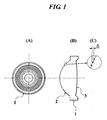
- FIG. 1 is a schematic view showing an objective lens 1 of the present embodiment, and (A) is a front view, (B) is a side view and (C) is a view expanding the side.
- the objective lens 1 is applied to, for example, an optical pickup device for recording/reproducing a high-density DVD, an MO or the like using a short wavelength light source such as a blue-violet laser diode, and has a function for converging laser light emitted from the light source onto an information recording surface of an optical disk.
- a short wavelength light source such as a blue-violet laser diode
- the objective lens 1 is a biconvex plastic single lens having two aspherical optical surfaces 2 and 3.
- a ring-shaped phase structure as a concentric diffraction structure where the optical axis is the center is formed on the optical surface 2.
- the ring-shaped phase structure has a step ⁇ in the direction of the optical axis at the boundary of each ring surface as a Fresnel lens.
- Laser light made incident to any ring surface of the ring-shaped phase structure is diffracted to the direction that is determined by the width of the ring surface in the direction perpendicular to the optical axis (in the present description, such a width of a ring surface in the direction perpendicular to the optical axis referred to as a "ring surface pitch").
- the ring-shaped phase structure has spherical aberration characteristics that spherical aberration changes in the undercorrected direction as the wavelength of the incident light increases. Because the refractive index of plastic single lens decreases owing to temperature rise, the spherical aberration changes in the overcorrected direction.
- the emission wavelength of a laser diode change in the direction to become long owing to temperature rise. For example, because a blue-violet laser diode has change of an emission wavelength by +0.05 nm/°C owing to temperature rise, the wavelength increases by 1.5 nm when the temperature rises by +30 °C.
- the focal length is set to satisfy the formulas (8) or (13A), and additionally, the correction of thermal aberration and the generation amount of chromatic spherical aberration are matched so as to respectively satisfy the formulas (11) to (13). Accordingly, the objective lens 1 is a plastic single lens having a high NA and yet a lens having good thermal aberration and chromatic spherical aberration.
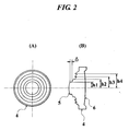
- FIG. 2 is a schematic view showing an objective lens 4 of another embodiment, and (A) is a front view and (B) is a side view.
- the optical surface 2 is, in the same way as the objective lens 1, applied to an optical pickup device for recording/reproducing a high-density DVD, an MO or the like using a short wavelength light source such as a blue-violet laser diode, and has a function for converging laser light emitted from the light source onto an information recording surface of an optical disk.
- a short wavelength light source such as a blue-violet laser diode
- the objective lens 4 is a biconvex plastic single lens having two aspherical optical surfaces 5 and 6.
- a ring-shaped phase structure as a concentric diffraction structure where the optical axis is the center is formed on the optical surface 5.
- the ring-shaped phase structure has a step ⁇ at the boundary of each ring surface in the optical axis direction, and each step ⁇ is determined in such a way that laser lights transmitted through adjacent ring surfaces have an optical path difference of wavelength of integral multiple of the wavelength in 25 °C, which is the design temperature.
- the ring-shaped phase structure comprises at least one ring surface formed to be displaced in the optical axis direction so as to have an optical path length shorter than the ring surface lying adjacent to the inside thereof, and at least one ring surface formed to be displaced in the optical axis direction so as to have an optical path length longer than the ring surface lying adjacent to the inside thereof, wherein the ring surface formed to be displaced in the optical axis direction so as to have an optical path length shorter than the ring surface lying adjacent to the inside thereof is formed on the closer side to the optical axis than the ring surface formed to be displaced in the optical axis direction so as to have an optical path length longer than the ring surface lying adjacent to the inside thereof.
- FIG. 3 is a view showing a situation of a wave front of a biconvex plastic single lens having two optical surfaces which are aspherical in case of temperature rising from a design temperature by 30 °C, and the abscissa axis denotes an effective radius of the optical surface and the ordinate axis denotes an optical path difference.
- spherical aberration is generated by the influence of change of the refractive index accompanying temperature rise, and a wave front is changed as line drawing Ag in FIG. 3.
- Line drawing Cg shows a situation of a wave front transmitted through the ring-shaped phase structure and plastic single lens in case of temperature rising from a design temperature by 30 °C. From line drawings Bg and Cg, it is understood that, owing to counterbalance of the wave front transmitted the ring-shaped phase structure and the wave front of the plastic single lens in case of temperature rising from the design temperature by 30 °C, a wave front of laser light converged on the information recording surface of an optical disk becomes a good wave front with no optical path difference from a broad view and thermal aberration of the plastic single lens is corrected by the ring-shaped phase structure.
- the focal length is set to satisfy the formulas (8) or (13A), and additionally, the correction of thermal aberration and the generation amount of chromatic spherical aberration are matched so as to respectively satisfy the formulas (11) to (13).
- the objective lens 4 is a plastic single lens having a high NA and yet a lens having good thermal aberration and chromatic spherical aberration in the same way as the objective lens 1.
- FIG. 4 is a view schematically showing the configuration of an optical pickup device (optical information recording/reproducing apparatus) equipped with the objective lens of the present invention.
- the optical pickup device 7 comprises a laser diode 8 as a light source and an objective lens 9.
- the laser diode 8 is a GaN-based blue-violet laser diode generating light having a wavelength of about 400 nm.
- a light source generating light having a wavelength of about 400 nm may employ an SHG blue-violet laser diode, besides the above-described GaN-based blue-violet laser diode.
- the objective lens 9 is any one of a plastic single lens whose focal length satisfies the formula (2), the objective lens 1 of FIG. 1 and the objective lens 4 of FIG. 2.
- the objective lens 9 comprises a flange portion 9A extending perpendicularly to the optical axis.
- the objective lens 9 can be attached to the optical pickup device 7 accurately by the flange portion 9A.
- the numerical aperture of the objective lens 9 on the side of an optical disk 10 is made not less than 0.80.
- a diverging light beam emitted from the laser diode 8 is transmitted through a polarization beam splitter 11 and passes through a collimating lens 12 and quarter-wave plate 13 to become a circularly polarized parallel light beam, and subsequently, has the light beam diameter regulated by a stop 14 and is made a spot that is passed through a protective layer 10A of the optical disk 10 of a high-density DVD and formed on an information recording surface 10B by the objective lens 9.
- focus control and tracking control are performed by an actuator 15 disposed around it.
- a reflected beam light modulated by information bit in the information recording surface 10B is transmitted again through the objective lens 9, the stop 14, the quarter-wave plate 13 and the collimating lens 12, and subsequently, is made a converged light beam, reflected by the polarization beam splitter 11, provided with astigmatic aberration by passing through a cylindrical lens 16 and concave lens 17, and converged on an optical detector 18. Subsequently, it is possible to read information recorded on the optical disk 10 by using an output signal of the optical detector 18.
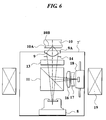
- FIG. 6 is a view schematically showing the configuration of another optical pickup device (optical information recording/reproducing apparatus) equipped with an objective lens of the present invention.
- the optical pickup device 7' comprises a laser diode 8 as a light source and an objective lens 9.
- the laser diode 8 is a GaN-based blue-violet laser diode generating light having a wavelength of about 400 nm.
- a light source generating light having a wavelength of about 400 nm may employ an SHG blue-violet laser diode, besides the above-described GaN-based blue-violet laser diode.
- the objective lens 9 is any one of a plastic single lens whose focal length satisfies the formula (6A), the above-described objective lens 1 of FIG. 1 and the objective lens 4 of FIG. 2.
- the objective lens 9 is an objective lens of the finite conjugate type for converging a diverging light beam emitted from the laser diode 8 on an information recording surface 10B through a protective layer 10A of the optical disk 10 of a high-density DVD.
- the objective lens 9 comprises a flange portion 9A extending perpendicularly to the optical axis.
- the objective lens 9 can be attached to the optical pickup device 7' accurately by the flange portion 9A.
- the numerical aperture of the objective lens 9 on the side of an optical disk 10 is made not less than 0.80.
- a diverging light beam emitted from the laser diode 8 is transmitted through a polarization beam splitter 11 and passes through a quarter-wave plate 13 to become circularly polarized light, and subsequently, has the light beam diameter regulated by a stop 14 and is made a spot that is passed through the protective layer 10A of the optical disk 10 of a high-density DVD and formed on the information recording surface 10B by the objective lens 9.
- a reflected beam light modulated by information bit in the information recording surface 10B is transmitted again through the objective lens 9, the stop 14 and the quarter-wave plate 13, and subsequently, is reflected by the polarization beam splitter 11, provided with astigmatic aberration by passing through a cylindrical lens 16 and concave lens 17, and converged on an optical detector 18. Subsequently, it is possible to read information recorded on the optical disk 10 by using an output signal of the optical detector 18.
- the laser diode 8, objective lens 9, polarization beam splitter 11, quarter-wave plate 13, cylindrical lens 16, concave lens 17 and optical detector 18 are modularized onto a substrate. In tracking control, these are monolithically driven by the actuator 19.
- Examples 1 to 6 are objective lenses applied to an optical pickup device for a high-density DVD in which the wavelength used for recording/reproducing information is 405 nm and the thickness of the protective layer is 0.1 mm.
- Example 1 is a plastic single lens where the generation amounts of thermal aberration and longitudinal chromatic aberration are suppressed low by setting the focal length so as to satisfy the formula (2), and both of Examples 2 and 3 are plastic single lenses where the thermal aberration is corrected by the effect of the ring-shaped phase structure formed on the first surface (the optical surface on the side of the light source).
- Example 4 is a plastic single lens of the finite conjugate type where the generation amounts of thermal aberration and longitudinal chromatic aberration are suppressed low by setting the focal length so as to satisfy the formula (6A), and both of Examples 5 and 6 are plastic single lenses of the finite conjugate type where the thermal aberration is corrected by the effect of the ring-shaped phase structure formed on the first surface (the optical surface on the side of the light source).
- Table 4 shows lens data of the objective lens of Example 1
- Table 5 shows lens data of the objective lens of Example 2
- Table 6 shows lens data of the objective lens of Example 3.
- r (mm) denotes a curvature radius
- d (mm) denotes a surface distance
- N405 denotes a refractive index at a wavelength of 405 nm
- vd denotes an Abbe number at the d-line.
- the change rate of the refractive index accompanying temperature rise of the plastic lens is -9.0 ⁇ 10 -5 and the change rate of the wavelength of incident light accompanying temperature rise is +0.05 nm/°C.
- the variation of the wavelength of a blue-violet laser diode owing to the mode hopping is assumed +1 nm and the focal position of the objective lens is fixed at the best image surface position of 405 nm.
- a back focal length fB in the present description indicates the distance along the optical axis between the optical surface S2 of the objective lens on the side of the optical information recording medium and a light beam incident surface S IN of the optical information recording medium.
- 80 lengths of ring-shaped phase structure as a diffraction structure whose boundaries comprise a step ⁇ of about 0.7 ⁇ m to 1.2 ⁇ m in the optical axis direction are formed within the effective diameter on the 1st surface of the objective lens of Example 2.
- the 1st order diffracted light is generated so as to have the maximum diffracted light quantity (i.e. the ring-shaped phase structure is optimized at a wavelength of 405 nm and a diffraction order of 1).
- the ring-shaped phase structure is optimized at a wavelength of 405 nm and a diffraction order of 1).
- a value of the formula (8A) in Example 2 is -42.
- 6 lengths of ring-shaped phase structure as a diffraction structure whose boundaries comprise a step ⁇ of about 1.5 ⁇ m to 2.3 ⁇ m in the optical axis direction are formed within the effective diameter on the 1st surface of the objective lens of Example 3.
- the 1st order diffracted light is generated so as to have the maximum diffracted light quantity (i.e. the ring-shaped phase structure is optimized at a wavelength of 405 nm and a diffraction order of 1).
- the ring-shaped phase structure is optimized at a wavelength of 405 nm and a diffraction order of 1).
- Both objective lenses of Examples 2 and 3 have a focal length set so as to satisfy the formula (8) in order to reduce the correction amount of thermal aberration, and additionally, have a configuration where the correction of thermal aberration and the generation amount of chromatic spherical aberration are matched so as to respectively satisfy the formulas (11) to (13). Accordingly, they are plastic single lenses with a high NA and yet a lens having good thermal aberration and chromatic spherical aberration as shown in Table 9.
- Example 2 0. 020 ⁇ rms 0. 022 ⁇ rms
- Example 3 0. 015 ⁇ rms 0. 015 ⁇ rms
- the change rate of the refractive index accompanying temperature rise of the plastic lens is -9.0 ⁇ 10 -5 and the change rate of the wavelength of incident light accompanying temperature rise is +0.05 nm/°C.
- Table 11 shows lens data of the objective lens of Example 5 and Table 15 shows lens data of the objective lens of Example 6.
- r (mm) denotes a curvature radius
- d (mm) denotes a surface distance
- N405 denotes a refractive index at a wavelength of 405 nm
- vd denotes an Abbe number at the d-line.
- Example 4 is a plastic single lens having a focal length of 0.30 mm, an NA of 0.85, a design wavelength of 405 nm, an image formation magnification of -0.084 and a design temperature of 25 °C.
- the focal length is set so as to satisfy the formula (6A)
- it is a plastic single lens of finite conjugate type with a high NA and yet a lens where both spherical aberrations in generation of thermal aberration and mode hopping are good as shown in Table 12.
- the change rate of the refractive index accompanying temperature rise of the plastic lens is -9.0 ⁇ 10 -5 and the change rate of the wavelength of incident light accompanying temperature rise is +0.05 nm/°C.
- the variation of the wavelength of a blue-violet laser diode owing to the mode hopping is assumed +1 nm and the focal position of the objective lens is fixed at the best image surface position of 405 nm.
- a stop regulating a light beam at the surface top position of the 1st surface in the objective lens of Example 5
- its stop diameter becomes 0.708 mm.
- 27 lengths of ring-shaped phase structure as a diffraction structure whose boundaries comprise a step ⁇ of about 0.7 ⁇ m to 1.1 ⁇ m in the optical axis direction are formed within the effective diameter on the 1st surface of the objective lens of Example 5.
- the 1st order diffracted light is generated so as to have the maximum diffracted light quantity (i.e. the ring-shaped phase structure is optimized at a wavelength of 405 nm and a diffraction order of 1 (the diffraction efficiency is the highest).
- thermal aberration (+30°C) Mode hopping(+1nm)
- Example 4 0. 028 ⁇ rms 0.024 ⁇ rms
- the objective lens of Example 5 has a focal length set so as to satisfy the formula (13A) in order to reduce the correction amount of thermal aberration, and additionally, have a configuration where the correction of thermal aberration and the generation amount of chromatic spherical aberration are matched so as to respectively satisfy the formulas (9) to (11). Accordingly, it is a plastic single lens having a high NA of the finite conjugate type and yet a lens having good thermal aberration and chromatic spherical aberration as shown in Table 14. Ring surface No.
- the change rate of the refractive index accompanying temperature rise of the plastic lens is -9.0 ⁇ 10 -5 and the change rate of the wavelength of incident light accompanying temperature rise is +0.05 nm/°C.
- a value of the formula (8A) in Example 5 is -45.
- a stop regulating a light beam at the surface top position of the 1st surface in the objective lens of Example 6
- its stop diameter becomes 0.702 mm.
- 7 lengths of ring-shaped phase structure as a diffraction structure whose boundaries comprise a step ⁇ of about 1.5 ⁇ m to 4.0 ⁇ m in the optical axis direction are formed within the effective diameter on the 1st surface of the objective lens of Example 6.
- the objective lens of Example 6 has a focal length set so as to satisfy the formula (6A) in order to reduce the correction amount of thermal aberration, and additionally, have a configuration where the correction of thermal aberration and the generation amount of chromatic spherical aberration are matched so as to respectively satisfy the formulas (11) to (13). Accordingly, it is a plastic single lens having a high NA of the finite conjugate type and yet a lens having good thermal aberration and chromatic spherical aberration as shown in Table 16.
- Example 6 0.020 ⁇ rms 0.032 ⁇ rms
- the change rate of the refractive index accompanying temperature rise of the plastic lens is -9.0 ⁇ 10 -5 and the change rate of the wavelength of incident light accompanying temperature rise is +0.05 nm/°C.
- the present invention it is possible to provide a plastic single lens applicable to an objective lens of an optical pickup device using a plastic single lens having a high NA, in which an available temperature range is sufficiently broad and converging ability due to mode hopping of a light source is degraded scarcely, and thereby it is possible to provide an optical pickup device and optical information recording/reproducing apparatus having high performance.
Landscapes
- Physics & Mathematics (AREA)
- Optics & Photonics (AREA)
- General Physics & Mathematics (AREA)
- Lenses (AREA)
- Optical Head (AREA)
- Optical Recording Or Reproduction (AREA)
Applications Claiming Priority (7)
| Application Number | Priority Date | Filing Date | Title |
|---|---|---|---|
| JP2002248207 | 2002-08-28 | ||
| JP2002248207 | 2002-08-28 | ||
| JP2002379657 | 2002-12-27 | ||
| JP2002379657 | 2002-12-27 | ||
| JP2003042269 | 2003-02-20 | ||
| JP2003042269A JP2004252135A (ja) | 2002-08-28 | 2003-02-20 | 光ピックアップ装置用の対物レンズ、光ピックアップ装置及び光情報記録再生装置 |
| PCT/JP2003/010994 WO2004021065A1 (ja) | 2002-08-28 | 2003-08-28 | 光ピックアップ装置用の対物レンズ、光ピックアップ装置及び光情報記録再生装置 |
Publications (2)
| Publication Number | Publication Date |
|---|---|
| EP1544652A1 true EP1544652A1 (de) | 2005-06-22 |
| EP1544652A4 EP1544652A4 (de) | 2009-12-02 |
Family
ID=31982122
Family Applications (1)
| Application Number | Title | Priority Date | Filing Date |
|---|---|---|---|
| EP03791401A Withdrawn EP1544652A4 (de) | 2002-08-28 | 2003-08-28 | Objektivlinse für eine optische bilderfassungseinrichtung, optische bilderfassungseinrichtung und optische informationsaufzeichnungs-/-wiedergabeeinrichtung |
Country Status (8)
| Country | Link |
|---|---|
| US (2) | US7606136B2 (de) |
| EP (1) | EP1544652A4 (de) |
| JP (1) | JP2004252135A (de) |
| KR (1) | KR101061347B1 (de) |
| CN (1) | CN100357780C (de) |
| AU (1) | AU2003257582A1 (de) |
| TW (2) | TW200411649A (de) |
| WO (1) | WO2004021065A1 (de) |
Cited By (1)
| Publication number | Priority date | Publication date | Assignee | Title |
|---|---|---|---|---|
| EP2141702A4 (de) * | 2007-04-27 | 2010-05-26 | Konica Minolta Opto Inc | Objektivlinse für einen optischen lesekopf und optischer lesekopf |
Families Citing this family (19)
| Publication number | Priority date | Publication date | Assignee | Title |
|---|---|---|---|---|
| JP2004252135A (ja) * | 2002-08-28 | 2004-09-09 | Konica Minolta Holdings Inc | 光ピックアップ装置用の対物レンズ、光ピックアップ装置及び光情報記録再生装置 |
| JPWO2005101393A1 (ja) * | 2004-04-13 | 2008-03-06 | コニカミノルタオプト株式会社 | 光ピックアップ装置用の対物光学系、光ピックアップ装置、光情報記録媒体のドライブ装置、集光レンズ、及び光路合成素子 |
| JP4529176B2 (ja) * | 2005-02-02 | 2010-08-25 | コニカミノルタオプト株式会社 | 光ピックアップ装置 |
| KR100724772B1 (ko) * | 2005-09-27 | 2007-06-04 | (주)아이엠 | 하이브리드렌즈의 수차보정방법 |
| TW200805347A (en) * | 2005-11-29 | 2008-01-16 | Konica Minolta Opto Inc | Objective lens for optical pickup apparatus, objective lens unit for optical pickup apparatus and optical pickup apparatus using the same |
| DE602007001995D1 (de) | 2006-04-06 | 2009-10-01 | Daewoo Electronics Corp | Optisches Informationswiedergabegerät und optisches Informationswiedergabeverfahren damit |
| US7889220B2 (en) * | 2006-10-31 | 2011-02-15 | Hewlett-Packard Development Company, L.P. | Device and method for maintaining optical energy density on a medium |
| WO2008065573A1 (en) * | 2006-11-27 | 2008-06-05 | Koninklijke Philips Electronics N.V. | Lens system for scanning device |
| JP4823114B2 (ja) * | 2007-03-23 | 2011-11-24 | 三洋電機株式会社 | 光ディスク装置 |
| WO2009066687A1 (ja) * | 2007-11-21 | 2009-05-28 | Konica Minolta Opto, Inc. | 対物レンズ及び撮像レンズ |
| JP2009217925A (ja) * | 2008-02-12 | 2009-09-24 | Hoya Corp | 光学素子および光情報記録再生装置用対物光学系 |
| JP2010153016A (ja) * | 2008-11-19 | 2010-07-08 | Hoya Corp | 光情報記録再生装置用対物レンズ、および光情報記録再生装置 |
| JP5363951B2 (ja) * | 2008-11-19 | 2013-12-11 | Hoya株式会社 | 光情報記録再生装置 |
| US8121012B2 (en) | 2008-11-19 | 2012-02-21 | Hoya Corporation | Objective lens and optical information recording/reproducing apparatus |
| JP5180138B2 (ja) * | 2009-04-13 | 2013-04-10 | 日立マクセル株式会社 | 光ピックアップレンズ |
| US8786965B2 (en) | 2009-09-30 | 2014-07-22 | Konica Minolta Opto, Inc. | Die processing method, die, objective lens, and optical pick-up device |
| CN102054490B (zh) * | 2009-10-29 | 2015-01-28 | Hoya株式会社 | 光学拾取头的光学系统和光学信息记录/再现装置 |
| CN104880753B (zh) * | 2015-05-05 | 2018-07-20 | 清华大学深圳研究生院 | 用于制作菲涅尔光栅的优化设计方法 |
| WO2020110525A1 (ja) * | 2018-11-30 | 2020-06-04 | パナソニックIpマネジメント株式会社 | 対物レンズ及び光ヘッド装置及び光情報装置と光ディスクシステム |
Family Cites Families (31)
| Publication number | Priority date | Publication date | Assignee | Title |
|---|---|---|---|---|
| JPH09311271A (ja) | 1996-05-20 | 1997-12-02 | ソニー株式会社 | 対物レンズ及び光学ピックアップ装置 |
| JP3385213B2 (ja) * | 1998-05-29 | 2003-03-10 | ペンタックス株式会社 | 光ヘッド用対物レンズ |
| US6349083B1 (en) * | 1998-07-13 | 2002-02-19 | Konica Corporation | Near field type optical disk recording reproducing apparatus, optical information recording medium recording reproducing apparatus, pickup apparatus, objective lens |
| JP2000035535A (ja) | 1998-07-21 | 2000-02-02 | Konica Corp | ピックアップ用対物レンズ |
| JP4434369B2 (ja) * | 1999-08-11 | 2010-03-17 | 旭硝子株式会社 | 対物レンズ |
| TW504582B (en) | 1999-09-01 | 2002-10-01 | Konishiroku Photo Ind | Objective lens for pickup and light pickup apparatus |
| JP4453131B2 (ja) | 1999-11-17 | 2010-04-21 | コニカミノルタホールディングス株式会社 | 光ピックアップ装置および対物レンズ |
| EP1102250A3 (de) * | 1999-11-17 | 2003-03-26 | Konica Corporation | Optische Abtastvorrichtung und Objektivlinse |
| US6594222B2 (en) * | 1999-12-28 | 2003-07-15 | Pentax Corporation | Objective lens for optical pick-up |
| JP2001283459A (ja) | 2000-01-26 | 2001-10-12 | Konica Corp | 光ピックアップ装置および光ピックアップ装置用対物レンズ |
| JP2001296471A (ja) * | 2000-04-14 | 2001-10-26 | Asahi Optical Co Ltd | 光ヘッド用対物レンズ |
| JP2002197712A (ja) | 2000-12-25 | 2002-07-12 | Konica Corp | 集光光学系、光ピックアップ装置及び再生装置 |
| EP1968054A3 (de) * | 2000-05-12 | 2012-03-07 | Konica Minolta Opto, Inc. | Optische Lesekopfvorrichtung |
| JP4660915B2 (ja) | 2000-05-12 | 2011-03-30 | コニカミノルタホールディングス株式会社 | 光ピックアップ装置 |
| JP4595184B2 (ja) * | 2000-10-02 | 2010-12-08 | コニカミノルタホールディングス株式会社 | 光ピックアップ装置及び対物レンズ |
| EP1327245B1 (de) * | 2000-10-03 | 2007-09-12 | Koninklijke Philips Electronics N.V. | Optischer kopf zum abtasten eines aufzeichnungsträgers |
| HUP0303190A2 (hu) * | 2000-10-16 | 2003-12-29 | Konica Corporation | Tárgylencse, kapcsoló lencse, fénykonvergáló optikai rendszer és optikai felvevő-lejátszó eszköz |
| CN100359577C (zh) * | 2000-10-30 | 2008-01-02 | 柯尼卡株式会社 | 物镜 |
| JP4131366B2 (ja) | 2000-10-30 | 2008-08-13 | コニカミノルタホールディングス株式会社 | 対物レンズ、光ピックアップ装置及び記録・再生装置 |
| KR100506565B1 (ko) * | 2000-11-16 | 2005-08-10 | 닛뽕빅터 가부시키가이샤 | 광 디스크용 대물 렌즈 |
| JP2002156579A (ja) | 2000-11-16 | 2002-05-31 | Victor Co Of Japan Ltd | 光ディスク用対物レンズ |
| US6807139B2 (en) * | 2001-04-12 | 2004-10-19 | Konica Corporation | Objective lens and optical pickup apparatus |
| US6597519B2 (en) * | 2001-04-26 | 2003-07-22 | Konica Corporation | Objective lens, optical pick-up apparatus and optical information recording reproducing apparatus |
| JP2003114383A (ja) * | 2001-07-30 | 2003-04-18 | Victor Co Of Japan Ltd | 光ディスク用対物レンズ、光ピックアップ装置、光ディスク記録再生装置及び光ディスク再生装置 |
| JP2003085806A (ja) * | 2001-09-07 | 2003-03-20 | Pentax Corp | 光ヘッド用対物レンズおよびこれを用いた光ヘッド |
| US6636366B1 (en) * | 2001-09-21 | 2003-10-21 | Victor Company Of Japan, Limited | Objective for optical disk, optical pickup, optical disk writer-reader, and optical disk reader |
| JP2003167188A (ja) | 2001-09-21 | 2003-06-13 | Victor Co Of Japan Ltd | 光ディスク用対物レンズ |
| JP2003167191A (ja) | 2001-09-21 | 2003-06-13 | Victor Co Of Japan Ltd | 光ディスク用対物レンズ、光ピックアップ装置、光ディスク記録再生装置及び光ディスク再生装置 |
| JP2003167189A (ja) | 2001-09-21 | 2003-06-13 | Victor Co Of Japan Ltd | 光ディスク用対物レンズ |
| JP2003167192A (ja) | 2001-09-21 | 2003-06-13 | Victor Co Of Japan Ltd | 光ディスク用対物レンズ、光ピックアップ装置、光ディスク記録再生装置及び光ディスク再生装置 |
| JP2004252135A (ja) * | 2002-08-28 | 2004-09-09 | Konica Minolta Holdings Inc | 光ピックアップ装置用の対物レンズ、光ピックアップ装置及び光情報記録再生装置 |
-
2003
- 2003-02-20 JP JP2003042269A patent/JP2004252135A/ja active Pending
- 2003-08-28 CN CNB038205424A patent/CN100357780C/zh not_active Expired - Fee Related
- 2003-08-28 TW TW092123779A patent/TW200411649A/zh not_active IP Right Cessation
- 2003-08-28 US US10/525,660 patent/US7606136B2/en not_active Expired - Fee Related
- 2003-08-28 KR KR1020057003182A patent/KR101061347B1/ko not_active Expired - Fee Related
- 2003-08-28 WO PCT/JP2003/010994 patent/WO2004021065A1/ja not_active Ceased
- 2003-08-28 AU AU2003257582A patent/AU2003257582A1/en not_active Abandoned
- 2003-08-28 EP EP03791401A patent/EP1544652A4/de not_active Withdrawn
- 2003-08-28 TW TW096130953A patent/TW200814036A/zh not_active IP Right Cessation
-
2009
- 2009-09-01 US US12/551,834 patent/US7920456B2/en not_active Expired - Fee Related
Non-Patent Citations (2)
| Title |
|---|
| No further relevant documents disclosed * |
| See also references of WO2004021065A1 * |
Cited By (2)
| Publication number | Priority date | Publication date | Assignee | Title |
|---|---|---|---|---|
| EP2141702A4 (de) * | 2007-04-27 | 2010-05-26 | Konica Minolta Opto Inc | Objektivlinse für einen optischen lesekopf und optischer lesekopf |
| US8199629B2 (en) | 2007-04-27 | 2012-06-12 | Konica Minolta Opto, Inc. | Objective lens for optical pickup device, and optical pickup device |
Also Published As
| Publication number | Publication date |
|---|---|
| TW200411649A (en) | 2004-07-01 |
| JP2004252135A (ja) | 2004-09-09 |
| TW200814036A (en) | 2008-03-16 |
| WO2004021065A1 (ja) | 2004-03-11 |
| CN1678935A (zh) | 2005-10-05 |
| TWI338891B (de) | 2011-03-11 |
| EP1544652A4 (de) | 2009-12-02 |
| US7606136B2 (en) | 2009-10-20 |
| CN100357780C (zh) | 2007-12-26 |
| TWI344645B (de) | 2011-07-01 |
| US7920456B2 (en) | 2011-04-05 |
| US20100054108A1 (en) | 2010-03-04 |
| US20050254399A1 (en) | 2005-11-17 |
| KR20050058522A (ko) | 2005-06-16 |
| KR101061347B1 (ko) | 2011-08-31 |
| AU2003257582A1 (en) | 2004-03-19 |
Similar Documents
| Publication | Publication Date | Title |
|---|---|---|
| US7920456B2 (en) | Objective lens for optical pickup device, optical pickup device and optical information recording/reproducing apparatus | |
| US6865025B2 (en) | Aberration compensating optical element, optical system, optical pickup device, recorder and reproducer | |
| US20060039266A1 (en) | Objective lens, light converging optical system, optical pickup apparatus, and recording/reproducing apparatus | |
| US6927923B2 (en) | Objective lens, converging optical system, optical pickup apparatus and recording and/or reproducing apparatus | |
| US7031076B2 (en) | Objective lens, optical system and optical pickup apparatus | |
| US6665130B2 (en) | Objective lens, optical pickup apparatus and recording and/or reproducing apparatus | |
| US6950383B2 (en) | Objective lens, light converging optical system, optical pickup apparatus, and recording and/or reproducing apparatus | |
| JP2004185797A (ja) | 光ピックアップ装置用光学系、光ピックアップ装置及び対物レンズ | |
| US7110344B2 (en) | Objective lens, optical pickup apparatus, and recording and/or reproducing apparatus | |
| US7733758B2 (en) | Objective lens for an optical pickup apparatus | |
| JP4296868B2 (ja) | 光ピックアップ装置用の光学系、光ピックアップ装置及び光情報記録再生装置 | |
| JP2002236252A (ja) | 対物レンズ、カップリングレンズ、集光光学系、光ピックアップ装置及び記録・再生装置 | |
| JP4803410B2 (ja) | 光ピックアップ装置用の対物レンズ、光ピックアップ装置及び光情報記録再生装置 | |
| JP4789169B2 (ja) | 色収差補正用光学素子、光学系、光ピックアップ装置及び記録・再生装置 | |
| JP4280896B2 (ja) | 光ピックアップ装置用光学系、光ピックアップ装置、光情報記録再生装置及び色収差補正素子 | |
| JP2003015032A (ja) | 対物レンズ、集光光学系、光ピックアップ装置、及び記録・再生装置 | |
| JP2002303788A (ja) | カップリングレンズ、集光光学系、光学素子、光ピックアップ装置、記録装置及び再生装置 | |
| CN1307455C (zh) | 物镜、光拾取器装置以及记录再现装置 | |
| JP2004199768A (ja) | 光ピックアップ装置及び光情報記録再生装置 | |
| JP2004109804A (ja) | 光ピックアップ装置用の対物レンズ、光ピックアップ装置及び光情報記録再生装置 | |
| JP2007316655A (ja) | 光ピックアップ装置用の対物レンズ、光ピックアップ装置及び光情報記録再生装置 | |
| JP2003322794A (ja) | 収差補正用光学素子、光学系、光ピックアップ装置及び記録再生装置 |
Legal Events
| Date | Code | Title | Description |
|---|---|---|---|
| PUAI | Public reference made under article 153(3) epc to a published international application that has entered the european phase |
Free format text: ORIGINAL CODE: 0009012 |
|
| 17P | Request for examination filed |
Effective date: 20050211 |
|
| AK | Designated contracting states |
Kind code of ref document: A1 Designated state(s): AT BE BG CH CY CZ DE DK EE ES FI FR GB GR HU IE IT LI LU MC NL PT RO SE SI SK TR |
|
| AX | Request for extension of the european patent |
Extension state: AL LT LV MK |
|
| DAX | Request for extension of the european patent (deleted) | ||
| RBV | Designated contracting states (corrected) |
Designated state(s): DE FR GB NL |
|
| A4 | Supplementary search report drawn up and despatched |
Effective date: 20091103 |
|
| RIC1 | Information provided on ipc code assigned before grant |
Ipc: G02B 5/18 20060101ALI20091028BHEP Ipc: G11B 7/135 20060101ALI20091028BHEP Ipc: G02B 13/00 20060101AFI20040316BHEP |
|
| 17Q | First examination report despatched |
Effective date: 20101015 |
|
| STAA | Information on the status of an ep patent application or granted ep patent |
Free format text: STATUS: THE APPLICATION IS DEEMED TO BE WITHDRAWN |
|
| 18D | Application deemed to be withdrawn |
Effective date: 20140301 |