EP1543932B1 - Formentlüftungsvorrichtung - Google Patents
Formentlüftungsvorrichtung Download PDFInfo
- Publication number
- EP1543932B1 EP1543932B1 EP04106576A EP04106576A EP1543932B1 EP 1543932 B1 EP1543932 B1 EP 1543932B1 EP 04106576 A EP04106576 A EP 04106576A EP 04106576 A EP04106576 A EP 04106576A EP 1543932 B1 EP1543932 B1 EP 1543932B1
- Authority
- EP
- European Patent Office
- Prior art keywords
- vent
- main body
- valve member
- mold
- sleeve
- Prior art date
- Legal status (The legal status is an assumption and is not a legal conclusion. Google has not performed a legal analysis and makes no representation as to the accuracy of the status listed.)
- Expired - Fee Related
Links
Images

Classifications
-
- B—PERFORMING OPERATIONS; TRANSPORTING
- B29—WORKING OF PLASTICS; WORKING OF SUBSTANCES IN A PLASTIC STATE IN GENERAL
- B29D—PRODUCING PARTICULAR ARTICLES FROM PLASTICS OR FROM SUBSTANCES IN A PLASTIC STATE
- B29D30/00—Producing pneumatic or solid tyres or parts thereof
- B29D30/06—Pneumatic tyres or parts thereof (e.g. produced by casting, moulding, compression moulding, injection moulding, centrifugal casting)
- B29D30/0601—Vulcanising tyres; Vulcanising presses for tyres
- B29D30/0662—Accessories, details or auxiliary operations
-
- B—PERFORMING OPERATIONS; TRANSPORTING
- B29—WORKING OF PLASTICS; WORKING OF SUBSTANCES IN A PLASTIC STATE IN GENERAL
- B29C—SHAPING OR JOINING OF PLASTICS; SHAPING OF MATERIAL IN A PLASTIC STATE, NOT OTHERWISE PROVIDED FOR; AFTER-TREATMENT OF THE SHAPED PRODUCTS, e.g. REPAIRING
- B29C33/00—Moulds or cores; Details thereof or accessories therefor
- B29C33/10—Moulds or cores; Details thereof or accessories therefor with incorporated venting means
-
- B—PERFORMING OPERATIONS; TRANSPORTING
- B29—WORKING OF PLASTICS; WORKING OF SUBSTANCES IN A PLASTIC STATE IN GENERAL
- B29D—PRODUCING PARTICULAR ARTICLES FROM PLASTICS OR FROM SUBSTANCES IN A PLASTIC STATE
- B29D30/00—Producing pneumatic or solid tyres or parts thereof
- B29D30/06—Pneumatic tyres or parts thereof (e.g. produced by casting, moulding, compression moulding, injection moulding, centrifugal casting)
- B29D30/0601—Vulcanising tyres; Vulcanising presses for tyres
- B29D30/0606—Vulcanising moulds not integral with vulcanising presses
-
- B—PERFORMING OPERATIONS; TRANSPORTING
- B29—WORKING OF PLASTICS; WORKING OF SUBSTANCES IN A PLASTIC STATE IN GENERAL
- B29D—PRODUCING PARTICULAR ARTICLES FROM PLASTICS OR FROM SUBSTANCES IN A PLASTIC STATE
- B29D30/00—Producing pneumatic or solid tyres or parts thereof
- B29D30/06—Pneumatic tyres or parts thereof (e.g. produced by casting, moulding, compression moulding, injection moulding, centrifugal casting)
- B29D30/08—Building tyres
-
- B—PERFORMING OPERATIONS; TRANSPORTING
- B29—WORKING OF PLASTICS; WORKING OF SUBSTANCES IN A PLASTIC STATE IN GENERAL
- B29D—PRODUCING PARTICULAR ARTICLES FROM PLASTICS OR FROM SUBSTANCES IN A PLASTIC STATE
- B29D30/00—Producing pneumatic or solid tyres or parts thereof
- B29D30/06—Pneumatic tyres or parts thereof (e.g. produced by casting, moulding, compression moulding, injection moulding, centrifugal casting)
- B29D30/0601—Vulcanising tyres; Vulcanising presses for tyres
- B29D30/0606—Vulcanising moulds not integral with vulcanising presses
- B29D2030/0607—Constructional features of the moulds
- B29D2030/0617—Venting devices, e.g. vent plugs or inserts
-
- B—PERFORMING OPERATIONS; TRANSPORTING
- B29—WORKING OF PLASTICS; WORKING OF SUBSTANCES IN A PLASTIC STATE IN GENERAL
- B29L—INDEXING SCHEME ASSOCIATED WITH SUBCLASS B29C, RELATING TO PARTICULAR ARTICLES
- B29L2030/00—Pneumatic or solid tyres or parts thereof
Definitions
- the present invention relates generally to vents for molds used in forming molded products and particularly but not exclusively to vents for tire molds.
- mold vents have thus been proposed and used to accomplish the above-stated objective.
- One approach is in the use of small diameter holes drilled through a mold wall normal to the interior surface.
- Another common approach is the use of "insert vents" that comprise small bore tubes introduced through the mold wall. Once trapped air has vented through the hole rubber begins to flow through the vent. However, the small diameter of the hole ensures that the rubber cures rapidly thus plugging the vent hole and sealing the mold. After completion of the tire curing process these plugs of rubber that are still attached to the tire surface are pulled out of the vent holes when the tire is extracted from the mold.
- Such plugs of rubber detract from the visual appeal of the molded tire and are usually removed by trimming.
- a trimming operation is time consuming and undesirably adds to the cost of the finished tire.
- vent sleeve is prone to becoming dislodged over time from the mold wall to which it attaches.
- a problem may exist when molds containing such vents are cleaned. Cleaning is commonly effected by blasting the mold surface with a mildly abrasive material such as a plastic grit.
- a mildly abrasive material such as a plastic grit.
- GB 2,339,163 discloses a further embodiment of a known vent that seeks to overcome the problem that occurs when a cleaning medium penetrates into the vent.
- the application discloses a vent configuration in which a first closure means (bias spring) is used in combination with a second closure means to close the vent when it is cold.
- This mechanical closure system is relative expensive and complicated to fabricate.
- the vent construction does not prevent the vent sleeve from becoming dislodged over time from the mold wall.
- vent plug system that can function effectively in venting air when open yet avoid vent obstruction when subjected to a cleaning procedure.
- a suitable vent system will be relatively simple and inexpensive to manufacture, incorporate and utilize within a mold, and replace if necessary.
- a vent for a mold having a mold cavity comprising a vent main body, a vent valve member disposed within the vent main body and moved by an expansion of a viscous material within the main body to cause the vent valve member to move with respect to the vent main body from a closed to an open position.
- a further aspect of the invention composes the expanding viscous material of silicon.
- a mold with improved venting having a mold cavity defined by a mold wall; a vent main body received within the mold wall; a viscous material contained within a portion of the vent main body; a vent valve member disposed within the vent main body to cause the vent valve member to move with respect to the vent main body from a closed to an open position. Expansion of the viscous material tightens an interference fit between the vent main body and the mold wall to which it attaches.
- the complementary shaped surfaces of the vent main body and the valve member are conical surfaces.
- a flow of material within the mold contacts the valve member to cause the valve member to move into the closed position.
- vent assembly includes a vent main body 12 and a vent closure member 14 (interchangeably referred to herein as "valve member").
- the vent main body 12 is generally a tubular structure or sleeve open at both ends to provide an air escape passage through the interior of the main body.
- a complementary external conical -shaped vent closure face 20 is disposed on the valve member 14. Closure of the valve occurs when the complementary conical-shaped surfaces of the closure face 20 and the vent seat 18 are brought together by downward movement of the valve member 14 within the main body 12. While a conical seat is preferred, other alternative seat variations known in the art are intended to be within the scope of the invention.
- An axial through-bore 21 extends through the sleeve 12.
- the external profile of the sleeve 12 is configured to provide an annular shoulder 22 at end 16 separated by a second annular shoulder 24 by annular recess or groove 26.
- the groove 26 functions to receive a surplus of segment material forced back by tightening the shoulders 22, 24 of the sleeve in a hole.
- a series of three orifices 28, 30, and 32 are spaced along the main body 12 and extend through the body sides to communicate with the internal through-bore 21.
- a transverse counter-bore 34 extends from orifice 32 through the main body 12.
- the through-bore 21 forms a reservoir 36 rearward from the counter-bore 34 and a lower end opening 38 to bore 21 extends from reservoir 36 through a lower end 40 of the main body 12.
- the reservoir 36 and counter-bore 34 are filled with an expansion agent 42 pursuant to the invention having the characteristic of volumetric expansion when subjected to a thermal energy source.
- an expansion agent 42 pursuant to the invention having the characteristic of volumetric expansion when subjected to a thermal energy source.
- One such agent is silicon; however alternative expansion agents known in the art may be employed pursuant to the invention.
- the valve member 14 is generally a tubular structure having a valve head 44 of relatively large diameter.
- the conical valve seat 20 represents an underside, rearward facing surface of head 44.
- Extending rearward from head 44 is a cylindrical valve body 46 that steps radially inward to a valve stem portion 48 along a conical annular shoulder 50.
- Stem 48 is generally cylindrical and steps outward at a rearward end of the valve 14 to a disc-flange 52.
- the construction of the members 12, 14 are from any suitably hard material such as, but not limited to, steel.
- the vent valve member 14 is received axially within the axial bore 21 of the vent main body 12. When fully inserted, as best seen from FIGS. 2 and 3, there exists a gap 54 between internal sidewalls defining bore 21 and the main body 12.
- the valve member 14 has an axial length sufficient to extend the end flange 52 into the reservoir 36 when the head 44 is fully seated against upper end 16 of the body 12.
- the diameter of the assembled vent plug is preferably in the range of two to three millimeters but may be varied according to the application.
- the rearward portion of the axial bore 21 is filled with the expansion agent such as silicon.
- the silicon fill extends from the opening 38 forward and fills the reservoir 36 and counter-bore 34. Silicon fills a rearward portion of gap 54 as shown and excess silicon material may be evacuated through the middle orifice 30.
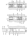
- FIGS. 4, 5, and 6 Implementation and operation of the vent plug 10 is illustrated in FIGS. 4, 5, and 6.
- the vent plug 10 is inserted into a socket bore 58 within a region 56 of a mold. Insertion may be effected through the use of a suitable tool such as a mallet.
- the vent plug 10 is driven into the socket bore 58 until end 16 is flush with the internal surface 59 of the mold.
- the groove 26 receives any surplus material forced back by a tightening of shoulders 22, 24 of the sleeve in the hole 58.
- the groove improves the maintenance of the position of the vent plug within the hole 58 by reducing the force required to install the vent plug. Reduction in force effected by the groove 26 also avoids damage to the head of the vent plug 16 and 44.
- the bore 58 is sized generally to accept the vent plug with minimal interference. Full insertion of the vent plug is shown in FIG. 5. In the position shown, annular flanges 22, 24 abut against internal walls of bore 58 in a friction fit.
- the diameter of the main body 12 is slightly undersized with respect to the diameter of the bore 58 such that a gap is defined between the body 12 and the bore sidewalls. In the condition shown, the head 44 of the valve 14 is seated against the main body 12 and blocks air from flowing therebetween.
- vent plug can be smaller than a conventional vent plug employing a coil spring to allow the passage of air.
- a vent plug with a diameter of 2 mm for shoulders 22, 24 is possible.
- the smaller dimensions possible through the use of the invention allows for a better evacuation of the air in a small area.
- the valve When temperature increases within the mold up to the curing temperature, the valve opens to the position shown in FIG. 6. Heating of the mold causes the silicon 42 to expand against the valve member 14. Expansion of the silicon against conical annular shoulder 50 forces the valve member 14 to move away in an axial direction, opening an air path 60 between the valve member 14 and the main body 12, beginning at the seated surfaces 18, 20. The axial movement of the valve 14 during the work corresponds to approximately 0.05 mm. The air path 60 proceeds along the outside of the valve member 14 until reaching orifice 28. The air then escapes through orifice 28 and progresses rearward along the gap 54 between the valve member 14 and the sleeve 12. Upon reaching the end 40 of the vent plug, the air flows into the mold bore 58 and is evacuated.
- Expansion of the silicon within the sleeve 12 further brings a complementary radially outward tightening of the sleeve against the mold bore sidewalls.
- the mold plug fit is tightened and unintended extraction of the mold plug from the mold wall during the heating and cooling cycle is avoided.
- trapped air escapes through the open vent until the rubber impinges onto the end head 44 and pushes the valve member 14 into the main body 12 to bring the conical faces 18, 20 into seated engagement so to close the air escape passage 60 therebetween.
- the conical surfaces 20 of the valve and 18 of the sleeve have a perfect fit because the elasticity of the silicon permits the valve 14 to have a limited movement, approximately 0.05 mm due to silicon expansion. This limited movement is beneficial and favors the adjustment of conical surfaces 20 and 18 as the valve closes.
- the silicon material 42 then cools to room temperature, the mold internal surfaces are cleaned by conventional means such as abrasive cleansing, and the cycle is repeated.
- the subject vent plug accomplishes the stated objectives by providing an assembly comprising relatively few component parts. Intricate and expensive means for biasing the valve member open are avoided.
- the use of silicon or other suitable expansion agent functions predictably through repeated thermal cycles.
- the expansion of the silicon not only acts to open the valve but also tightens the sleeve within the mold sidewall.
- the valve closes as when rubber flowing within the mold contacts head 44 and forces the valve member 14 into seated engagement with the main body 12. At room temperature, the valve is in the closed position represented in FIGS. 2 and 3 and allows for a sand blasting of the mold internal surfaces with the vent plugs flush within the mold sidewalls.
- the subject vent valve is mounted flush with the interior wall of the mold and the valve seats flush with the molding surface.
- a sprueless end product such as a tire.
- the elimination of sprues avoids the cost of post-mold removal and enhances the appearance of the finished product.
Landscapes
- Engineering & Computer Science (AREA)
- Mechanical Engineering (AREA)
- Moulds For Moulding Plastics Or The Like (AREA)
Claims (9)
- Eine Entlüftungsvorrichtung, umfassend
einen Entlüftungsvorrichtungshauptkörper (12), ein in einem Behälter (36) innerhalb eines Abschnitts an dem Entlüftungsvorrichtungshauptkörper (12) enthaltenes viskoses Material (42), und
ein innerhalb des Entlüftungsvorrichtungshauptkörpers (12) angeordnetes Entlüftungsvorrichtungsventilelement (14), wobei das Entlüftungsvorrichtungsventilelement durch Expansion des viskosen Materials (42) bewegbar ist, um zu veranlassen, dass das Entlüftungsvorrichtungsventilelement (14) sich in Bezug zu dem Entlüftungsvorrichtungshauptkörper (12) von einer geschlossenen in eine offene Position bewegt. - Eine Entlüftungsvorrichtung gemäß Anspruch 1, wobei das Expansionsmaterial Silikon umfasst.
- Eine Entlüftungsvorrichtung gemäß Anspruch 1 oder 2, wobei der Entlüftungsvorrichtungshauptkörper (12) eine längliche Hülse umfasst, die das Expansionsmaterial (42) enthält, und der Hauptkörper (12) wenigstens ein Entlüftungsvorrichtungsluftloch (28, 30, 32) beinhaltet, das sich darin erstreckt, um Luft um das Ventilelement (14) herum entweichen zu lassen, wenn es in der offenen Position ist.
- Eine Entlüftungsvorrichtung gemäß Anspruch 3, wobei die Hülse ein Fach (36) zum isolierten Enthalten des Expansionsmaterials relativ zu dem Entlüftungsvorrichtungsluftloch umfasst.
- Eine Entlüftungsvorrichtung gemäß Anspruch 1, wobei das Ventilelement (14) und der Hauptkörper (12) komplementär geformte Oberflächen umfassen, die in abdichtendem Eingriff sind, wenn das Ventilelement in der geschlossenen Position ist.
- Eine Entlüftungsvorrichtung gemäß wenigstens einem der vorhergehenden Ansprüche, wobei das Ventilelement (14) sich zwischen der geschlossenen und offenen Position hin- und herbewegt, wobei das Expansionsmaterial (42) sich volumetrisch ausdehnt, um das Ventilelement (14) zu veranlassen, sich in die offene Position zu bewegen, und sich volumetrisch zusammenzieht, wenn das Ventilelement (14) in die geschlossene Position zurückkehrt.
- Eine Form mit einer Entlüftung, welche einen wenigstens teilweise durch eine Formwand definierten Formhohlraum umfasst, und eine Entlüftungsvorrichtung gemäß wenigstens einem der vorhergehenden Ansprüche, wobei der Entlüftungsvorrichtungshauptkörper (12) innerhalb der Formwand aufgenommen wird.
- Eine Form gemäß Anspruch 7, wobei der Entlüftungsvorrichtungshauptkörper (12) eine längliche Hülse umfasst und das Entlüftungsvorrichtungsventilelement sich innerhalb der Hülse axial zwischen der offenen und der geschlossenen Position bewegt.
- Eine Form gemäß Anspruch 8, wobei die Hülse in einer Presspassung in einer Formhohlraumwand aufgenommen wird und eine ringförmige Nut (26) beinhaltet, die zur Aufnahme verlagerten Materials von der Formhohlraumwand, wenn die Hülse in die Formhohlraumwand gepresst wird, positioniert ist.
Applications Claiming Priority (2)
| Application Number | Priority Date | Filing Date | Title |
|---|---|---|---|
| US741712 | 2003-12-19 | ||
| US10/741,712 US6871831B1 (en) | 2003-12-19 | 2003-12-19 | Mold vent |
Publications (2)
| Publication Number | Publication Date |
|---|---|
| EP1543932A1 EP1543932A1 (de) | 2005-06-22 |
| EP1543932B1 true EP1543932B1 (de) | 2007-03-21 |
Family
ID=34314226
Family Applications (1)
| Application Number | Title | Priority Date | Filing Date |
|---|---|---|---|
| EP04106576A Expired - Fee Related EP1543932B1 (de) | 2003-12-19 | 2004-12-14 | Formentlüftungsvorrichtung |
Country Status (7)
| Country | Link |
|---|---|
| US (1) | US6871831B1 (de) |
| EP (1) | EP1543932B1 (de) |
| JP (1) | JP4669276B2 (de) |
| KR (1) | KR101120291B1 (de) |
| CN (1) | CN1308127C (de) |
| BR (1) | BRPI0405413A (de) |
| DE (1) | DE602004005407D1 (de) |
Families Citing this family (15)
| Publication number | Priority date | Publication date | Assignee | Title |
|---|---|---|---|---|
| JP4507818B2 (ja) * | 2004-10-18 | 2010-07-21 | 横浜ゴム株式会社 | タイヤ成形用金型及びタイヤ成形用金型のベントホールに使用するプラグ |
| US8048247B2 (en) * | 2004-12-28 | 2011-11-01 | Pirelli Tyre S.P.A. | Method and apparatus for manufacturing tyres for vehicle wheels |
| KR101217986B1 (ko) | 2006-01-24 | 2013-01-02 | 요코하마 고무 가부시키가이샤 | 타이어 성형용 금형, 타이어 성형용 금형의 벤트 홀에 사용하는 플러그 및 그 타이어 성형용 금형을 사용하여 제조한 타이어 |
| SK287193B6 (sk) * | 2006-03-03 | 2010-03-08 | Glebus Alloys Europe S.R.O. | Odvzdušňovací ventil do odvzdušňovacích otvorov vulkanizačných foriem |
| JP4946369B2 (ja) * | 2006-11-09 | 2012-06-06 | 横浜ゴム株式会社 | タイヤ加硫成形用金型のベントホールに使用する排気プラグ |
| US7530803B2 (en) | 2007-05-08 | 2009-05-12 | Bridgestone Firestone North American Tire, Llc | Insert for a tire mold vent |
| FI119626B (fi) | 2007-07-11 | 2009-01-30 | Wd Racing Oy | Vulkanointimuotin ilmanpoistoventtiili |
| CN101808796B (zh) * | 2008-01-28 | 2013-05-08 | 株式会社斋藤金型制作所 | 模具内部气体的排气结构和具有该结构的模具 |
| DE102009031453A1 (de) * | 2009-07-02 | 2011-01-05 | Werner Beuerlein | Gussform mit Entlüfter |
| CN102313057B (zh) * | 2011-08-23 | 2012-11-21 | 山东豪迈机械科技股份有限公司 | 改进的无气孔轮胎模具排气阀 |
| FR3024068B1 (fr) * | 2014-07-22 | 2016-08-12 | Michelin & Cie | Moule pour la vulcanisation d'un pneumatique comportant des elements mobiles obtenus par frittage laser |
| DE102016209910A1 (de) * | 2016-06-06 | 2017-12-07 | Continental Reifen Deutschland Gmbh | Entlüftungseinheit für eine Vulkanisationsform eines Fahrzeugluftreifens |
| FI129777B (en) * | 2017-04-12 | 2022-08-31 | Wd Racing Oy | VALVE INSERT AND BREATHER VALVE |
| US11007735B2 (en) | 2019-08-08 | 2021-05-18 | The Goodyear Tire & Rubber Company | Tire mold |
| KR102401473B1 (ko) * | 2020-10-27 | 2022-05-25 | 금호타이어 주식회사 | 타이어 가황금형용 벤트리스 플러그 |
Family Cites Families (24)
| Publication number | Priority date | Publication date | Assignee | Title |
|---|---|---|---|---|
| CH547138A (de) * | 1972-10-05 | 1974-03-29 | Hodler Fritz | Entlueftungsventil zum schliessen des entlueftungskanals von giessformen. |
| US4021168A (en) | 1976-02-12 | 1977-05-03 | The General Tire & Rubber Company | Tire mold having washered nails inserted in the vents |
| US3989430A (en) | 1976-02-12 | 1976-11-02 | The General Tire & Rubber Company | Tire mold having nails inserted in the vents |
| DE2615177C3 (de) | 1976-04-08 | 1983-12-15 | Uniroyal Gmbh, 5100 Aachen | Vorrichtung zum Herstellen von austriebfreien Formteilen aus einer Formmasse aus Elastomeren oder aus vernetzbaren bzw. härtbaren Kunststoffen |
| US4347212A (en) * | 1980-08-26 | 1982-08-31 | Corn States Metal Fabricators, Inc. | Method for forming a tire |
| US4492554A (en) | 1980-08-26 | 1985-01-08 | Corn States Metal Fabricators, Inc. | Valve unit for a mold vent |
| US4351789A (en) | 1981-07-27 | 1982-09-28 | The B. F. Goodrich Company | Mold and process for molding |
| US4708609A (en) | 1984-03-22 | 1987-11-24 | Bridgestone Corporation | Tire manufacturing mold |
| JPS60232914A (ja) * | 1984-05-02 | 1985-11-19 | Bridgestone Corp | 成形用金型における通気装置 |
| US4795331A (en) | 1986-09-15 | 1989-01-03 | The Goodyear Tire & Rubber Company | Mold vent plug |
| JPH0722946B2 (ja) * | 1987-06-16 | 1995-03-15 | いすゞ自動車株式会社 | プラスチック成形金型のエア−ベント装置 |
| US4740145A (en) | 1987-07-15 | 1988-04-26 | The Firestone Tire & Rubber Company | Flash-free vented tire mold |
| US4759701A (en) | 1987-09-18 | 1988-07-26 | Corn States Metal Fabricators, Inc. | Venting unit for a rubber article forming mold having vents |
| US4987946A (en) | 1989-09-05 | 1991-01-29 | General Motors Corporation | Valve for mold cavity gas removal system |
| JPH0564818A (ja) * | 1991-02-28 | 1993-03-19 | Yokohama Rubber Co Ltd:The | 浮力材の製造方法 |
| JP2989463B2 (ja) * | 1994-02-03 | 1999-12-13 | 三洋電機株式会社 | 射出成形金型 |
| US5626887A (en) | 1994-10-24 | 1997-05-06 | Texas Instruments Incorporated | Air exhaust mold plunger |
| DE19543276C1 (de) | 1995-11-20 | 1997-02-06 | Continental Ag | Reifenvulkanisationsform mit Entlüftung |
| GB9623770D0 (en) | 1996-11-15 | 1997-01-08 | Sp Tyres Uk Ltd | Mould vents |
| GB9708584D0 (en) * | 1997-04-29 | 1997-06-18 | Sp Tyres Uk Ltd | Mould vents |
| GB2339163B (en) * | 1998-05-27 | 2002-12-24 | Dunlop Tyres Ltd | Mould vents |
| JP4255613B2 (ja) * | 2000-12-07 | 2009-04-15 | 日本碍子株式会社 | タイヤ成形用金型 |
| JP2003170479A (ja) * | 2001-12-10 | 2003-06-17 | Sony Corp | 金型のガス抜き方法と装置、及び射出成形機 |
| ITTO20020213A1 (it) * | 2002-03-12 | 2003-09-12 | Agusta Spa | Metodo di formatura di una pala per un rotore di un elicottero. |
-
2003
- 2003-12-19 US US10/741,712 patent/US6871831B1/en not_active Expired - Fee Related
-
2004
- 2004-12-09 BR BR0405413-0A patent/BRPI0405413A/pt not_active IP Right Cessation
- 2004-12-14 EP EP04106576A patent/EP1543932B1/de not_active Expired - Fee Related
- 2004-12-14 DE DE602004005407T patent/DE602004005407D1/de active Active
- 2004-12-16 JP JP2004364006A patent/JP4669276B2/ja not_active Expired - Fee Related
- 2004-12-17 KR KR1020040107987A patent/KR101120291B1/ko not_active IP Right Cessation
- 2004-12-20 CN CNB2004101019302A patent/CN1308127C/zh not_active Expired - Fee Related
Also Published As
| Publication number | Publication date |
|---|---|
| BRPI0405413A (pt) | 2005-09-20 |
| US6871831B1 (en) | 2005-03-29 |
| KR101120291B1 (ko) | 2012-03-06 |
| JP4669276B2 (ja) | 2011-04-13 |
| EP1543932A1 (de) | 2005-06-22 |
| DE602004005407D1 (de) | 2007-05-03 |
| JP2005178383A (ja) | 2005-07-07 |
| CN1308127C (zh) | 2007-04-04 |
| KR20050062439A (ko) | 2005-06-23 |
| CN1628947A (zh) | 2005-06-22 |
Similar Documents
| Publication | Publication Date | Title |
|---|---|---|
| EP1543932B1 (de) | Formentlüftungsvorrichtung | |
| EP0875350B1 (de) | Entlüftungskanäle mit Ventil für Formwerkzeuge | |
| CZ291837B6 (cs) | Odvzdušňovací ventil a vulkanizační forma pro výrobu pneumatik | |
| EP0842749A1 (de) | Entlüftungskanäle für Formwerkzeuge | |
| CN101432111A (zh) | 用于硫化模的排气孔的排气阀 | |
| EP1655123A1 (de) | Formwerkzeug mit einer Grataussparung, Verfahren zu deren Nutzung und damit hergestellte Gegenstände | |
| JPS5985354A (ja) | 金型用ガス抜き装置 | |
| GB2339163A (en) | Mould vents | |
| EP3366446B1 (de) | Wachsspritzgiessmaschine und einspritzdüse im wachsausschmelzguss | |
| US4995445A (en) | Gas vent system of a mold | |
| US7014446B2 (en) | Quick release volume control inserts for molding machines | |
| US5152951A (en) | Vented tire mold and method for vacuum molding | |
| WO2007075395A2 (en) | Injection molding apparatus having swiveling nozzles | |
| US5059380A (en) | Tire mold vent plug and method | |
| US4759701A (en) | Venting unit for a rubber article forming mold having vents | |
| US6206336B1 (en) | Venting of molds | |
| US6000925A (en) | Gas assisted injection molding system | |
| US2908313A (en) | Pneumatic tire valve | |
| JP3831031B2 (ja) | ガス併用射出成形用金型 | |
| JPH0866946A (ja) | 合成樹脂成形品の射出成形装置 | |
| JPS5933294B2 (ja) | 成形金型 | |
| KR0142729B1 (ko) | 공기빼기 밸브 | |
| EP0763414A1 (de) | Gasspritzgiessdüse zur Verwendung in gasunterstütztem Spritzgiessen von Kunststoff | |
| JPH0312443Y2 (de) | ||
| KR20030069699A (ko) | 타이어 가류 금형의 에어 플러그 |
Legal Events
| Date | Code | Title | Description |
|---|---|---|---|
| PUAI | Public reference made under article 153(3) epc to a published international application that has entered the european phase |
Free format text: ORIGINAL CODE: 0009012 |
|
| AK | Designated contracting states |
Kind code of ref document: A1 Designated state(s): AT BE BG CH CY CZ DE DK EE ES FI FR GB GR HU IE IS IT LI LT LU MC NL PL PT RO SE SI SK TR |
|
| AX | Request for extension of the european patent |
Extension state: AL BA HR LV MK YU |
|
| 17P | Request for examination filed |
Effective date: 20051222 |
|
| AKX | Designation fees paid |
Designated state(s): DE FR GB IT |
|
| GRAP | Despatch of communication of intention to grant a patent |
Free format text: ORIGINAL CODE: EPIDOSNIGR1 |
|
| GRAS | Grant fee paid |
Free format text: ORIGINAL CODE: EPIDOSNIGR3 |
|
| GRAA | (expected) grant |
Free format text: ORIGINAL CODE: 0009210 |
|
| AK | Designated contracting states |
Kind code of ref document: B1 Designated state(s): DE FR GB IT |
|
| REG | Reference to a national code |
Ref country code: GB Ref legal event code: FG4D |
|
| REF | Corresponds to: |
Ref document number: 602004005407 Country of ref document: DE Date of ref document: 20070503 Kind code of ref document: P |
|
| PG25 | Lapsed in a contracting state [announced via postgrant information from national office to epo] |
Ref country code: DE Free format text: LAPSE BECAUSE OF FAILURE TO SUBMIT A TRANSLATION OF THE DESCRIPTION OR TO PAY THE FEE WITHIN THE PRESCRIBED TIME-LIMIT Effective date: 20070622 |
|
| ET | Fr: translation filed | ||
| PLBE | No opposition filed within time limit |
Free format text: ORIGINAL CODE: 0009261 |
|
| STAA | Information on the status of an ep patent application or granted ep patent |
Free format text: STATUS: NO OPPOSITION FILED WITHIN TIME LIMIT |
|
| 26N | No opposition filed |
Effective date: 20071227 |
|
| GBPC | Gb: european patent ceased through non-payment of renewal fee |
Effective date: 20081214 |
|
| PG25 | Lapsed in a contracting state [announced via postgrant information from national office to epo] |
Ref country code: GB Free format text: LAPSE BECAUSE OF NON-PAYMENT OF DUE FEES Effective date: 20081214 |
|
| PGFP | Annual fee paid to national office [announced via postgrant information from national office to epo] |
Ref country code: IT Payment date: 20131217 Year of fee payment: 10 |
|
| PGFP | Annual fee paid to national office [announced via postgrant information from national office to epo] |
Ref country code: FR Payment date: 20141124 Year of fee payment: 11 |
|
| PG25 | Lapsed in a contracting state [announced via postgrant information from national office to epo] |
Ref country code: IT Free format text: LAPSE BECAUSE OF NON-PAYMENT OF DUE FEES Effective date: 20141214 |
|
| REG | Reference to a national code |
Ref country code: FR Ref legal event code: ST Effective date: 20160831 |
|
| PG25 | Lapsed in a contracting state [announced via postgrant information from national office to epo] |
Ref country code: FR Free format text: LAPSE BECAUSE OF NON-PAYMENT OF DUE FEES Effective date: 20151231 |