EP1541742A1 - Wäschetrockner mit einer Rollenlagerung - Google Patents
Wäschetrockner mit einer Rollenlagerung Download PDFInfo
- Publication number
- EP1541742A1 EP1541742A1 EP04029132A EP04029132A EP1541742A1 EP 1541742 A1 EP1541742 A1 EP 1541742A1 EP 04029132 A EP04029132 A EP 04029132A EP 04029132 A EP04029132 A EP 04029132A EP 1541742 A1 EP1541742 A1 EP 1541742A1
- Authority
- EP
- European Patent Office
- Prior art keywords
- roller
- bearing according
- gap
- region
- roller bearing
- Prior art date
- Legal status (The legal status is an assumption and is not a legal conclusion. Google has not performed a legal analysis and makes no representation as to the accuracy of the status listed.)
- Granted
Links
Images
Classifications
-
- D—TEXTILES; PAPER
- D06—TREATMENT OF TEXTILES OR THE LIKE; LAUNDERING; FLEXIBLE MATERIALS NOT OTHERWISE PROVIDED FOR
- D06F—LAUNDERING, DRYING, IRONING, PRESSING OR FOLDING TEXTILE ARTICLES
- D06F58/00—Domestic laundry dryers
- D06F58/02—Domestic laundry dryers having dryer drums rotating about a horizontal axis
- D06F58/04—Details
- D06F58/06—Mountings for the rotating drums
Definitions
- the invention relates to a clothes dryer with a roller bearing, in which the Laundry drum is additionally guided in the region of its feed opening by means of rollers, wherein the rollers support the laundry drum on the drum basket drum and the Bearing axes of the rollers arranged at one in the region of the feed opening fixed support member are rotatably mounted.
- Such a tumble dryer is known from DE 196 15 822 C1.
- the established Support part encloses the feed opening of the laundry drum and is used as a plastic molded part formed, which is arranged fixed to the housing walls of the clothes dryer.
- the plastic molding carries the storage for the laundry drum and is as a part of the Process air ducts formed.
- this plastic molding for receiving in the Process air duct section to be used lint filter and designed to hinge the door.
- the Casters for supporting the laundry drum shell outside the sphere of influence with Fluff loaded process air flow arranged.
- the casters are, facing the Loading opening seen arranged on the back of the stationary housing part.
- the fixed support member for the Storage of the rollers is not designed as a process air duct section.
- the usually large-volume laundry drums require a more sustainable support of the laundry drum in the area of the loading opening.
- the known tumble dryer Miele T 6251 is the Support member for the storage of rollers designed as a partition.
- the partition encloses the laundry drum in the area of the front loading opening and forms together with the housing walls, the process air guide portion of the front air duct.
- This Front air duct is a large surface filter arranged below the laundry drum.
- the Casters are seen on the loading drum with respect to the loading opening of the laundry drum Front of the fixed support member or the partition arranged.
- the rollers support the laundry drum on the laundry drum circumference in the front of the Laundry drum off.
- the frontal laundry drum wall, in which the feed opening is arranged has a perforated annular region over which the process air flow out of the laundry drum in the direction of large surface filter.
- the rollers are at This described training process air flow in the sphere of influence of the Process air flow arranged.
- a disadvantage of this arrangement is that small items of laundry such as apron ribbons, threads etc. due to the guided over the front Wäschetrommellochung process air flow can pass through the holes in the area of the running surfaces of the rollers.
- the Laundry items can wrap around the axles of the casters, resulting in increased noise and leads to premature wear of the rollers.
- Another disadvantage is that the in the process air flow entrained lint through the front drum hole in the area of Running surfaces and the storage of rollers can get. The deposit of lint on treads and bearings leads to increased noise and premature wear the caster assembly.
- the invention thus raises the problem of the roller arrangement of a tumble dryer To protect against damage by washing parts and the deposition of lint from the To avoid process air flow at the bearing of the roller.
- the achievable with the present invention consist in particular that in the range of At least one roller arrangement means are provided which the gap area between cover rotating roller and fixed partition approximately gap-free or fill out.
- a Guard provided, which is arranged concentrically to the bearing axis and the Fills gap area.
- a further development of this embodiment is the cup-shaped design of the Protective disc, whereby the axially directed running surface of the roller in the area of Between space or in the gap area cup-shaped is enclosed. The protective screen is against twisting with a corresponding fuse e.g. secured a locking pin.
- a further advantageous embodiment of the invention provides, the means as at the partition form arranged approach that covers the gap area.
- the approach can be the axial Cover the directional running surface of the roller in the gap area.
- the approach can be the roller enclose annular. It is possible, even a portion of the scope of To enclose roller.
- a further advantageous embodiment is provided in the Near the vulnerable areas on the rollers Small diameter holes in the to arrange fixed partition, via which an air flow in the negative pressure area is sucked and entrains the lint.
- the outlet opening of a To arrange air supply line in the vicinity of the roller assembly. The air inlet opening of this Air supply line is outside the process air duct.
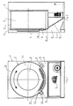
- the tumble dryer is formed with a housing (1).
- the laundry drum (2) in a known manner via a not shown rear bearing and a front side, described in more detail below roller bearings, rotatably mounted.
- the front and rear storages of the laundry drum (2) are received by a support frame (3) shown schematically in Figure 2.
- this support frame (3) On the Front side, this support frame (3) as a support member (3 ') formed partition (4) for the Support the rollers (5).
- the partition (4) encloses the laundry drum (2) in Area of the front loading opening (6).
- This partition (4) forms together with the housing walls (7) the process air guide portion (8) of the front air duct.
- This front air duct is a large surface filter (9) below the laundry drum (2) arranged.
- the rollers (5) are facing the feed opening (6) of the Laundry drum (2) seen on the front of the fixed support member (3 ') and the Partition (4) arranged.
- the rollers (5) support the laundry drum (2) on Laundry drum circumference (2 ') in the front region of the laundry drum (2) on one Raceway surface (10) from.
- the front-side laundry drum wall (11), in which the Charging opening (6) is arranged, has a perforated annular region (12), via which the process air flow from the laundry drum (2) in the direction of large area filter (9) to be led.
- the rollers (5) are in this described embodiment of the Process air duct arranged in the sphere of influence of the process air flow.
- FIGS. 1, 2, 3 and 4 This area is shown in FIGS. 1, 2, 3 and 4 as a gap area or catchment area (14).
- Figure 3 is the endangered Cleavage region or catchment area (14) shown on an enlarged scale as a detail A.
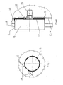
- Figure 4 shows a first embodiment of the invention wherein the gap between fixed support member (3 ') or partition (4) and rotating roller side surface (17) or the gap area / catchment area (14) at least approximately gap-free through a protective pane (16) is completed.
- the protective disk (16) is arranged concentrically to the bearing axis (15). at In the exemplary embodiment shown here, the protective pane (16) covers part of the Running surface (5 ') of the roller (5) in the gap region (14).
- the protective disk (16) is shaped in such a way that they cup-shaped a portion of the tread (5 ') in the critical catchment area (14) encloses.
- This version is particularly suitable when the tumble dryer no Laundry drum (2) enclosing partition (4) as a supporting part (3 ') for the rollers (5) but has a cross member, not shown for receiving the rollers (5).
- the Protective disk (16) is secured against rotation by means of e.g. a locking pin (18) against Secured turning.
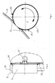
- Figure 5 shows another embodiment of the invention wherein the gap between fixed support member (3 ') or partition (4) and rotating roller side surface (17) or the gap area / catchment area (14) at least approximately gap-free through a projection (19) is covered.
- the projection (19) is formed on the support part (3 ') or the partition wall (4) or attached by a screw etc.
- the approach is designed to be a Section of the tread (5 ') in the critical catchment area (14) surrounds annular.
- FIG. 6 shows an exemplary embodiment with a roller arrangement in which, in the vicinity of the at least one in the dividing wall (4) arranged ventilation opening (20) is provided.
- the ventilation opening (20) is near the Feed area (14) or the contact point of the roller surface (5 ') of the roller (5) and Raceway surface (10) of the laundry drum (2) arranged.
- As a ventilation opening (20) preferably two holes with a small diameter in the range of 3 to 6 mm intended. About this air supply fresh air is sucked into the negative pressure area, resulting in eliminating the lint deposits leads.
- the fixed support member in the range of at least one roller arrangement an outlet opening (nozzle) of an air supply line assigned.
- the suction port of the air supply line is outside the negative pressure range the front air duct.
Landscapes
- Engineering & Computer Science (AREA)
- Textile Engineering (AREA)
- Detail Structures Of Washing Machines And Dryers (AREA)
- Rolls And Other Rotary Bodies (AREA)
Abstract
Description
- Figur 1
- schematisch den erfindungsgemäßen Wäschetrockner mit der Anordnung der Laufrollen einer Rollenlagerung in der Vorderansicht,
- Figur 2
- den Wäschetrockner in der Seitenansicht,
- Figur 3
- eine dem Wäschetrommelumfang zugeordnete Laufrolle als Einzelheit A,
- Figur 4
- die Laufrolle als Einzelheit in der Seitenansicht mit Schutzscheibe,
- Figur 5
- die Anordnung der Laufrolle und die Ausbildung des Ansatzes an der Trennwand,
- Figur 6
- die Laufrolle als Einzelheit A mit Belüftung.
Claims (11)
- Wäschetrockner mit einer Rollenlagerung, bei dem die Wäschetrommel im Bereich ihrer Beschickungsöffnung mittels Laufrollen zusätzlich geführt ist, wobei die Laufrollen die Wäschetrommel am Wäschetrommelmantel abstützen und die Lagerachsen der Laufrollen an einem im Bereich der Beschickungsöffnung angeordneten feststehenden Tragteil drehbar gelagert sind,
dadurch gekennzeichnet, dass im Bereich von mindestens einer Laufrollenanordnung Mittel (16, 19) vorgesehen sind, die den Zwischenraum (14, Spaltbereich/Einzugsbereich) zwischen feststehendem Tragteil (3') und drehender Laufrollenseitenfläche (17) wenigstens annähernd spaltfrei ausfüllen. - Wäschetrockner mit einer Rollenlagerung nach Anspruch 1,
dadurch gekennzeichnet, dass mindestens eine Laufrollenanordnung mit einer den Zwischenraum (14, Spaltbereich/Einzugsbereich) zwischen feststehendem Tragteil (3') und drehender Laufrollenseitenfläche (17) wenigstens annähernd spaltfrei ausfüllenden Schutzscheibe (16) ausgebildet ist, die konzentrisch zur Lagerachse (15) angeordnet ist. - Wäschetrockner mit einer Rollenlagerung nach Anspruch 2,
dadurch gekennzeichnet, dass die Schutzscheibe (16) die Lauffläche (5') der Laufrolle (5) im Spaltbereich (14) topfförmig umschließt. - Wäschetrockner mit einer Rollenlagerung nach Anspruch 3,
dadurch gekennzeichnet, dass die Schutzscheibe (16) an dem Tragteil (3') mittels einer Verdrehsicherung (18) gegen Mitdrehen gesichert ist. - Wäschetrockner mit einer Rollenlagerung nach Anspruch 1,
dadurch gekennzeichnet, dass das Tragteil (3') im Bereich von mindestens einer Laufrollenanordnung mit einem den Zwischenraum (14, Spaltbereich/Einzugsbereich) zwischen feststehendem Tragteil (3') und drehender Laufrollenseitenfläche (17) überdeckenden Ansatz (19) ausgebildet ist. - Wäschetrockner mit einer Rollenlagerung nach Anspruch 5,
dadurch gekennzeichnet, dass der Ansatz (19) die Lauffläche (5') der Laufrolle (5) im Spaltbereich (14) ringförmig umschließt. - Wäschetrockner mit einer Rollenlagerung nach Anspruch 5,
dadurch gekennzeichnet, dass der Ansatz (19) einen Teilbereich des Umfanges der Laufrolle (5) umschließt. - Wäschetrockner mit einer Rollenlagerung nach mindestens einem der vorgenannten Ansprüche,
dadurch gekennzeichnet, dass einer Laufrollenanordnung im Bereich der Lagerung wenigstens eine in der Trennwand (4) angeordnete Belüftungsöffnung (20) zugeordnet ist. - Wäschetrockner mit einer Rollenlagerung nach Anspruch 8,
dadurch gekennzeichnet, dass die Belüftungsöffnung (20) nahe des an die Berührungsstelle von Laufrollenfläche (5') der Laufrolle (5) und Laufringfläche (10) der Wäschetrommel (2) angrenzenden Bereichs angeordnet ist. - Wäschetrockner mit einer Rollenlagerung nach Anspruch 9,
dadurch gekennzeichnet, dass die Belüftungsöffnung (20) als Bohrung mit einem geringen Durchmesser von 3 bis zu 6 mm ausgebildet ist. - Wäschetrockner mit einer Rollenlagerung nach mindestens einem der vorgenannten Ansprüche 1 bis 10,
dadurch gekennzeichnet, dass dem feststehenden Tragteil (3') im Bereich von wenigstens einer Laufrollenanordnung eine Austrittsöffnung (Düse) einer Luftzufuhrleitung zugeordnet ist und dass die Ansaugöffnung der Luftzufuhrleitung außerhalb des Unterdruckbereichs der vorderen Luftführung liegt.
Applications Claiming Priority (4)
| Application Number | Priority Date | Filing Date | Title |
|---|---|---|---|
| DE10358130 | 2003-12-12 | ||
| DE10358131 | 2003-12-12 | ||
| DE10358131A DE10358131B3 (de) | 2003-12-12 | 2003-12-12 | Wäschetrockner mit einer Rollenlagerung |
| DE10358130 | 2003-12-12 |
Publications (2)
| Publication Number | Publication Date |
|---|---|
| EP1541742A1 true EP1541742A1 (de) | 2005-06-15 |
| EP1541742B1 EP1541742B1 (de) | 2007-10-03 |
Family
ID=34524070
Family Applications (1)
| Application Number | Title | Priority Date | Filing Date |
|---|---|---|---|
| EP04029132A Expired - Lifetime EP1541742B1 (de) | 2003-12-12 | 2004-12-09 | Wäschetrockner mit einer Rollenlagerung |
Country Status (3)
| Country | Link |
|---|---|
| EP (1) | EP1541742B1 (de) |
| AT (1) | ATE374854T1 (de) |
| DE (1) | DE502004005122D1 (de) |
Cited By (4)
| Publication number | Priority date | Publication date | Assignee | Title |
|---|---|---|---|---|
| EP2103732A1 (de) * | 2008-03-19 | 2009-09-23 | Electrolux Home Products Corporation N.V. | Wäschetrockner |
| WO2009132969A1 (en) * | 2008-05-02 | 2009-11-05 | Arcelik Anonim Sirketi | A dryer |
| EP2990521A1 (de) * | 2014-08-29 | 2016-03-02 | Electrolux Appliances Aktiebolag | Wäschetrockner |
| DE102014112431A1 (de) * | 2014-08-29 | 2016-03-17 | Miele & Cie. Kg | Trockner insbesondere gewerblicher Wäschetrockner |
Citations (2)
| Publication number | Priority date | Publication date | Assignee | Title |
|---|---|---|---|---|
| US4754556A (en) * | 1986-08-18 | 1988-07-05 | Whirlpool Corporation | Front bulkhead mounting for a dryer |
| DE19615822C1 (de) * | 1996-04-20 | 1997-05-07 | Bauknecht Hausgeraete | Wäschetrockner |
-
2004
- 2004-12-09 EP EP04029132A patent/EP1541742B1/de not_active Expired - Lifetime
- 2004-12-09 AT AT04029132T patent/ATE374854T1/de not_active IP Right Cessation
- 2004-12-09 DE DE502004005122T patent/DE502004005122D1/de not_active Expired - Lifetime
Patent Citations (2)
| Publication number | Priority date | Publication date | Assignee | Title |
|---|---|---|---|---|
| US4754556A (en) * | 1986-08-18 | 1988-07-05 | Whirlpool Corporation | Front bulkhead mounting for a dryer |
| DE19615822C1 (de) * | 1996-04-20 | 1997-05-07 | Bauknecht Hausgeraete | Wäschetrockner |
Cited By (8)
| Publication number | Priority date | Publication date | Assignee | Title |
|---|---|---|---|---|
| EP2103732A1 (de) * | 2008-03-19 | 2009-09-23 | Electrolux Home Products Corporation N.V. | Wäschetrockner |
| EP2476795A1 (de) * | 2008-03-19 | 2012-07-18 | Electrolux Home Products Corporation N.V. | Wäschetrockner |
| RU2486300C2 (ru) * | 2008-03-19 | 2013-06-27 | Электролюкс Хоум Продактс Корпорейшн Н.В. | Барабанная сушильная машина |
| EP2476795B1 (de) | 2008-03-19 | 2019-10-30 | Electrolux Home Products Corporation N.V. | Wäschetrockner |
| WO2009132969A1 (en) * | 2008-05-02 | 2009-11-05 | Arcelik Anonim Sirketi | A dryer |
| EP2990521A1 (de) * | 2014-08-29 | 2016-03-02 | Electrolux Appliances Aktiebolag | Wäschetrockner |
| DE102014112431A1 (de) * | 2014-08-29 | 2016-03-17 | Miele & Cie. Kg | Trockner insbesondere gewerblicher Wäschetrockner |
| DE102014112431B4 (de) * | 2014-08-29 | 2017-03-23 | Miele & Cie. Kg | Wäschetrockner insbesondere gewerblicher Wäschetrockner |
Also Published As
| Publication number | Publication date |
|---|---|
| DE502004005122D1 (de) | 2007-11-15 |
| ATE374854T1 (de) | 2007-10-15 |
| EP1541742B1 (de) | 2007-10-03 |
Similar Documents
| Publication | Publication Date | Title |
|---|---|---|
| DE112011101522B4 (de) | Wäschevorrichtung | |
| DE10245216B4 (de) | Trommelwaschmaschine | |
| DE102012207977A1 (de) | Wäschebehandlungsmaschine | |
| DE60021346T2 (de) | Waschmaschine mit Auswuchtvorrichtung | |
| EP3290572A1 (de) | Wäschepflegegerät mit einer umleitvorrichtung | |
| WO2012076410A2 (de) | Dichtungsmanschette für eine waschmaschine | |
| DE19702196A1 (de) | Vorrichtung zum Reinigen eines Transportbandes | |
| EP1541742B1 (de) | Wäschetrockner mit einer Rollenlagerung | |
| DE647772C (de) | Trommeltrockenmaschine, insbesondere fuer Textilstoffe in losem Zustande | |
| DE10358131B3 (de) | Wäschetrockner mit einer Rollenlagerung | |
| DE2746463C2 (de) | Offenend-Spinnaggregat | |
| EP1476599B1 (de) | Trommelwaschmaschine mit einer von vorn beschickbaren wäschetrommel | |
| DE2333555B2 (de) | Lagerung für den Spinnrotor einer Offenend-Spinnvorrichtung | |
| DE102009001323A1 (de) | Vorrichtung und Verfahren zum Schleudern von Wäsche | |
| DE102005029767A1 (de) | Vorrichtung an einer Spinnereivorbereitungsmaschine,insbesondere Karde, Krempel, Reiniger o. dgl., mit einem Kühlsystem | |
| DE1710043A1 (de) | Vorrichtung zum kontinuierlichen ringlosen Feinspinnen von Textilfaser mit einer einen Saugeffekt ausloesenden rotierenden Spinnkammer | |
| DE102007063264A1 (de) | Lagerungseinheit für hohe Drehzahlen | |
| DE1240806B (de) | Trommeltrockner fuer Kleidungsstuecke od. dgl. | |
| EP2986765B1 (de) | Streckwerk für eine strickmaschine | |
| DE19651417A1 (de) | Auflöseeinrichtung für Offenend-Spinnmaschinen | |
| DE2226284B2 (de) | Mehrfachdraht-Zwirnspindel zur Verarbeitung von Glasseide | |
| DE19733298C2 (de) | Rauhmaschine | |
| DE2158731A1 (de) | Vorrichtung zur Auflockerung von Fa sermatenal fur Textilmaschinen, insbe sondere für spindellose Feinspinnma schinen | |
| DE102018202761A1 (de) | Lageranordnung für eine Wäschetrommel und Laugenbehälter mit einer solchen Lageranordnung | |
| EP0579849B1 (de) | Trommelwaschmaschine mit einem Laugenbehälter aus Kunststoff |
Legal Events
| Date | Code | Title | Description |
|---|---|---|---|
| PUAI | Public reference made under article 153(3) epc to a published international application that has entered the european phase |
Free format text: ORIGINAL CODE: 0009012 |
|
| AK | Designated contracting states |
Kind code of ref document: A1 Designated state(s): AT BE BG CH CY CZ DE DK EE ES FI FR GB GR HU IE IS IT LI LT LU MC NL PL PT RO SE SI SK TR |
|
| AX | Request for extension of the european patent |
Extension state: AL BA HR LV MK YU |
|
| 17P | Request for examination filed |
Effective date: 20051109 |
|
| AKX | Designation fees paid |
Designated state(s): AT BE BG CH CY CZ DE DK EE ES FI FR GB GR HU IE IS IT LI LT LU MC NL PL PT RO SE SI SK TR |
|
| GRAP | Despatch of communication of intention to grant a patent |
Free format text: ORIGINAL CODE: EPIDOSNIGR1 |
|
| GRAS | Grant fee paid |
Free format text: ORIGINAL CODE: EPIDOSNIGR3 |
|
| GRAA | (expected) grant |
Free format text: ORIGINAL CODE: 0009210 |
|
| AK | Designated contracting states |
Kind code of ref document: B1 Designated state(s): AT BE BG CH CY CZ DE DK EE ES FI FR GB GR HU IE IS IT LI LT LU MC NL PL PT RO SE SI SK TR |
|
| REG | Reference to a national code |
Ref country code: GB Ref legal event code: FG4D Free format text: NOT ENGLISH |
|
| REG | Reference to a national code |
Ref country code: CH Ref legal event code: EP |
|
| REG | Reference to a national code |
Ref country code: IE Ref legal event code: FG4D Free format text: LANGUAGE OF EP DOCUMENT: GERMAN |
|
| REF | Corresponds to: |
Ref document number: 502004005122 Country of ref document: DE Date of ref document: 20071115 Kind code of ref document: P |
|
| GBT | Gb: translation of ep patent filed (gb section 77(6)(a)/1977) |
Effective date: 20071127 |
|
| REG | Reference to a national code |
Ref country code: GB Ref legal event code: 746 Effective date: 20080201 |
|
| PG25 | Lapsed in a contracting state [announced via postgrant information from national office to epo] |
Ref country code: ES Free format text: LAPSE BECAUSE OF FAILURE TO SUBMIT A TRANSLATION OF THE DESCRIPTION OR TO PAY THE FEE WITHIN THE PRESCRIBED TIME-LIMIT Effective date: 20080114 Ref country code: SE Free format text: LAPSE BECAUSE OF FAILURE TO SUBMIT A TRANSLATION OF THE DESCRIPTION OR TO PAY THE FEE WITHIN THE PRESCRIBED TIME-LIMIT Effective date: 20080103 |
|
| PG25 | Lapsed in a contracting state [announced via postgrant information from national office to epo] |
Ref country code: LT Free format text: LAPSE BECAUSE OF FAILURE TO SUBMIT A TRANSLATION OF THE DESCRIPTION OR TO PAY THE FEE WITHIN THE PRESCRIBED TIME-LIMIT Effective date: 20071003 Ref country code: IS Free format text: LAPSE BECAUSE OF FAILURE TO SUBMIT A TRANSLATION OF THE DESCRIPTION OR TO PAY THE FEE WITHIN THE PRESCRIBED TIME-LIMIT Effective date: 20080203 Ref country code: PT Free format text: LAPSE BECAUSE OF FAILURE TO SUBMIT A TRANSLATION OF THE DESCRIPTION OR TO PAY THE FEE WITHIN THE PRESCRIBED TIME-LIMIT Effective date: 20080303 Ref country code: PL Free format text: LAPSE BECAUSE OF FAILURE TO SUBMIT A TRANSLATION OF THE DESCRIPTION OR TO PAY THE FEE WITHIN THE PRESCRIBED TIME-LIMIT Effective date: 20071003 Ref country code: BG Free format text: LAPSE BECAUSE OF FAILURE TO SUBMIT A TRANSLATION OF THE DESCRIPTION OR TO PAY THE FEE WITHIN THE PRESCRIBED TIME-LIMIT Effective date: 20080103 |
|
| ET | Fr: translation filed | ||
| REG | Reference to a national code |
Ref country code: IE Ref legal event code: FD4D |
|
| BERE | Be: lapsed |
Owner name: MIELE & CIE. K.G. Effective date: 20071231 |
|
| PG25 | Lapsed in a contracting state [announced via postgrant information from national office to epo] |
Ref country code: MC Free format text: LAPSE BECAUSE OF NON-PAYMENT OF DUE FEES Effective date: 20071231 Ref country code: CZ Free format text: LAPSE BECAUSE OF FAILURE TO SUBMIT A TRANSLATION OF THE DESCRIPTION OR TO PAY THE FEE WITHIN THE PRESCRIBED TIME-LIMIT Effective date: 20071003 Ref country code: DK Free format text: LAPSE BECAUSE OF FAILURE TO SUBMIT A TRANSLATION OF THE DESCRIPTION OR TO PAY THE FEE WITHIN THE PRESCRIBED TIME-LIMIT Effective date: 20071003 |
|
| PLBE | No opposition filed within time limit |
Free format text: ORIGINAL CODE: 0009261 |
|
| STAA | Information on the status of an ep patent application or granted ep patent |
Free format text: STATUS: NO OPPOSITION FILED WITHIN TIME LIMIT |
|
| PG25 | Lapsed in a contracting state [announced via postgrant information from national office to epo] |
Ref country code: SK Free format text: LAPSE BECAUSE OF FAILURE TO SUBMIT A TRANSLATION OF THE DESCRIPTION OR TO PAY THE FEE WITHIN THE PRESCRIBED TIME-LIMIT Effective date: 20071003 Ref country code: RO Free format text: LAPSE BECAUSE OF FAILURE TO SUBMIT A TRANSLATION OF THE DESCRIPTION OR TO PAY THE FEE WITHIN THE PRESCRIBED TIME-LIMIT Effective date: 20071003 |
|
| 26N | No opposition filed |
Effective date: 20080704 |
|
| PG25 | Lapsed in a contracting state [announced via postgrant information from national office to epo] |
Ref country code: BE Free format text: LAPSE BECAUSE OF NON-PAYMENT OF DUE FEES Effective date: 20071231 |
|
| PG25 | Lapsed in a contracting state [announced via postgrant information from national office to epo] |
Ref country code: IE Free format text: LAPSE BECAUSE OF FAILURE TO SUBMIT A TRANSLATION OF THE DESCRIPTION OR TO PAY THE FEE WITHIN THE PRESCRIBED TIME-LIMIT Effective date: 20071003 |
|
| PG25 | Lapsed in a contracting state [announced via postgrant information from national office to epo] |
Ref country code: EE Free format text: LAPSE BECAUSE OF FAILURE TO SUBMIT A TRANSLATION OF THE DESCRIPTION OR TO PAY THE FEE WITHIN THE PRESCRIBED TIME-LIMIT Effective date: 20071003 Ref country code: GR Free format text: LAPSE BECAUSE OF FAILURE TO SUBMIT A TRANSLATION OF THE DESCRIPTION OR TO PAY THE FEE WITHIN THE PRESCRIBED TIME-LIMIT Effective date: 20080104 |
|
| PG25 | Lapsed in a contracting state [announced via postgrant information from national office to epo] |
Ref country code: FI Free format text: LAPSE BECAUSE OF FAILURE TO SUBMIT A TRANSLATION OF THE DESCRIPTION OR TO PAY THE FEE WITHIN THE PRESCRIBED TIME-LIMIT Effective date: 20071003 |
|
| PG25 | Lapsed in a contracting state [announced via postgrant information from national office to epo] |
Ref country code: AT Free format text: LAPSE BECAUSE OF NON-PAYMENT OF DUE FEES Effective date: 20071209 |
|
| PG25 | Lapsed in a contracting state [announced via postgrant information from national office to epo] |
Ref country code: SI Free format text: LAPSE BECAUSE OF FAILURE TO SUBMIT A TRANSLATION OF THE DESCRIPTION OR TO PAY THE FEE WITHIN THE PRESCRIBED TIME-LIMIT Effective date: 20071003 |
|
| PG25 | Lapsed in a contracting state [announced via postgrant information from national office to epo] |
Ref country code: CY Free format text: LAPSE BECAUSE OF FAILURE TO SUBMIT A TRANSLATION OF THE DESCRIPTION OR TO PAY THE FEE WITHIN THE PRESCRIBED TIME-LIMIT Effective date: 20071003 |
|
| REG | Reference to a national code |
Ref country code: CH Ref legal event code: PL |
|
| PG25 | Lapsed in a contracting state [announced via postgrant information from national office to epo] |
Ref country code: LU Free format text: LAPSE BECAUSE OF NON-PAYMENT OF DUE FEES Effective date: 20071209 |
|
| PG25 | Lapsed in a contracting state [announced via postgrant information from national office to epo] |
Ref country code: TR Free format text: LAPSE BECAUSE OF FAILURE TO SUBMIT A TRANSLATION OF THE DESCRIPTION OR TO PAY THE FEE WITHIN THE PRESCRIBED TIME-LIMIT Effective date: 20071003 Ref country code: HU Free format text: LAPSE BECAUSE OF FAILURE TO SUBMIT A TRANSLATION OF THE DESCRIPTION OR TO PAY THE FEE WITHIN THE PRESCRIBED TIME-LIMIT Effective date: 20080404 |
|
| PG25 | Lapsed in a contracting state [announced via postgrant information from national office to epo] |
Ref country code: CH Free format text: LAPSE BECAUSE OF NON-PAYMENT OF DUE FEES Effective date: 20081231 Ref country code: LI Free format text: LAPSE BECAUSE OF NON-PAYMENT OF DUE FEES Effective date: 20081231 |
|
| REG | Reference to a national code |
Ref country code: FR Ref legal event code: PLFP Year of fee payment: 12 |
|
| REG | Reference to a national code |
Ref country code: FR Ref legal event code: PLFP Year of fee payment: 13 |
|
| REG | Reference to a national code |
Ref country code: FR Ref legal event code: PLFP Year of fee payment: 14 |
|
| PGFP | Annual fee paid to national office [announced via postgrant information from national office to epo] |
Ref country code: NL Payment date: 20221226 Year of fee payment: 19 Ref country code: GB Payment date: 20221220 Year of fee payment: 19 Ref country code: FR Payment date: 20221222 Year of fee payment: 19 Ref country code: DE Payment date: 20221231 Year of fee payment: 19 |
|
| PGFP | Annual fee paid to national office [announced via postgrant information from national office to epo] |
Ref country code: IT Payment date: 20221222 Year of fee payment: 19 |
|
| REG | Reference to a national code |
Ref country code: DE Ref legal event code: R119 Ref document number: 502004005122 Country of ref document: DE |
|
| REG | Reference to a national code |
Ref country code: NL Ref legal event code: MM Effective date: 20240101 |
|
| GBPC | Gb: european patent ceased through non-payment of renewal fee |
Effective date: 20231209 |
|
| PG25 | Lapsed in a contracting state [announced via postgrant information from national office to epo] |
Ref country code: NL Free format text: LAPSE BECAUSE OF NON-PAYMENT OF DUE FEES Effective date: 20240101 |
|
| PG25 | Lapsed in a contracting state [announced via postgrant information from national office to epo] |
Ref country code: NL Free format text: LAPSE BECAUSE OF NON-PAYMENT OF DUE FEES Effective date: 20240101 |
|
| PG25 | Lapsed in a contracting state [announced via postgrant information from national office to epo] |
Ref country code: DE Free format text: LAPSE BECAUSE OF NON-PAYMENT OF DUE FEES Effective date: 20240702 |
|
| PG25 | Lapsed in a contracting state [announced via postgrant information from national office to epo] |
Ref country code: GB Free format text: LAPSE BECAUSE OF NON-PAYMENT OF DUE FEES Effective date: 20231209 |
|
| PG25 | Lapsed in a contracting state [announced via postgrant information from national office to epo] |
Ref country code: FR Free format text: LAPSE BECAUSE OF NON-PAYMENT OF DUE FEES Effective date: 20231231 |
|
| PG25 | Lapsed in a contracting state [announced via postgrant information from national office to epo] |
Ref country code: GB Free format text: LAPSE BECAUSE OF NON-PAYMENT OF DUE FEES Effective date: 20231209 Ref country code: FR Free format text: LAPSE BECAUSE OF NON-PAYMENT OF DUE FEES Effective date: 20231231 Ref country code: DE Free format text: LAPSE BECAUSE OF NON-PAYMENT OF DUE FEES Effective date: 20240702 |
|
| PG25 | Lapsed in a contracting state [announced via postgrant information from national office to epo] |
Ref country code: IT Free format text: LAPSE BECAUSE OF NON-PAYMENT OF DUE FEES Effective date: 20231209 |