EP1541395A1 - Aérateur pour un véhicule - Google Patents
Aérateur pour un véhicule Download PDFInfo
- Publication number
- EP1541395A1 EP1541395A1 EP03104607A EP03104607A EP1541395A1 EP 1541395 A1 EP1541395 A1 EP 1541395A1 EP 03104607 A EP03104607 A EP 03104607A EP 03104607 A EP03104607 A EP 03104607A EP 1541395 A1 EP1541395 A1 EP 1541395A1
- Authority
- EP
- European Patent Office
- Prior art keywords
- vanes
- guide
- ventilation outlet
- outlet according
- housing frame
- Prior art date
- Legal status (The legal status is an assumption and is not a legal conclusion. Google has not performed a legal analysis and makes no representation as to the accuracy of the status listed.)
- Withdrawn
Links
Images


Classifications
-
- B—PERFORMING OPERATIONS; TRANSPORTING
- B60—VEHICLES IN GENERAL
- B60H—ARRANGEMENTS OF HEATING, COOLING, VENTILATING OR OTHER AIR-TREATING DEVICES SPECIALLY ADAPTED FOR PASSENGER OR GOODS SPACES OF VEHICLES
- B60H1/00—Heating, cooling or ventilating [HVAC] devices
- B60H1/34—Nozzles; Air-diffusers
- B60H1/345—Nozzles; Air-diffusers with means for adjusting divergence, convergence or oscillation of air stream
-
- B—PERFORMING OPERATIONS; TRANSPORTING
- B60—VEHICLES IN GENERAL
- B60H—ARRANGEMENTS OF HEATING, COOLING, VENTILATING OR OTHER AIR-TREATING DEVICES SPECIALLY ADAPTED FOR PASSENGER OR GOODS SPACES OF VEHICLES
- B60H1/00—Heating, cooling or ventilating [HVAC] devices
- B60H1/34—Nozzles; Air-diffusers
- B60H2001/3471—Details of actuators
Definitions
- the invention relates to an adjustable ventilation outlet for a motor vehicle with a housing frame and a number in this rotatably arranged Vanes.
- a ventilation outlet for a motor vehicle of the type mentioned is from the US 5 063 833 known.
- a Row of vanes rotatably mounted about mutually parallel pivot axes.
- On the outside of the housing lead with the axes of the vanes connected levers with pins arranged at their ends to a link plate, in their guide slots engage the pins each.
- a motor-driven Displacement of the cam plate in a direction perpendicular to the pivot axes The vanes then move the pegs along the guide slots predetermined paths, whereby the guide vanes each have an individual, obtained from the position of the cam plate dependent orientation.
- Problematic in this ventilation outlet is that provided outside the housing frame Gate control of the vanes relatively expensive in their Assembly is. Furthermore, it is structurally unstable and thus prone to failure during operation.
- the above-defined ventilation outlet made possible by specifying the guide slots in the link plate virtually any desired relative orientation of the Guide vanes to each other, the respective orientation by a simple Moving the link plate is adjustable.
- the advantage here is that the link plate acts directly on the vanes, so that no consuming, from the housing frame leading out linkage or the like for this connection is required.
- the vanes can rather in per se known Way used in the rack and then there with the link plate get connected.
- the link plate is preferably coupled to an actuating element, via a manual or automatic (e.g., controlled by the actuator of an air conditioner) Displacement movement of the link plate in a direction perpendicular to the pivot axes of the vanes is possible, so that the pins of the vanes be moved in the guide slots of the link plate. This it allows in a simple way, given by the link plate alignment possibility the guide vanes for a targeted setting use.
- the guide slots in the link plate can in principle any course have and thus corresponding relative orientations of the vanes realize each other.
- the guide slots in the link plate be shaped so that these the vanes between one another parallel and a divergent orientation, the divergence the orientation is related to the air flow through the ventilation outlet. In the parallel orientation, the vanes therefore provide close bundling or Concentration of the exiting air flow, while these in the divergent Alignment for a wide distribution or diffusion of the air flow to care.
- the guide slots can also be shaped so that a converging orientation of the vanes is possible, whereby a still stronger concentration of the air flow is made possible to a kind of spot beam.
- the guide slots in the link plate are preferably open on one side, so that from this side of the respective pin a vane in the guide slot can be introduced.
- the guide slots are narrowed in their peripheral opening area, so that the described insertion of the pins against a certain resistance must be done. This resistance then prevents the pins from later in an undesirable manner by itself the guide slots of the link plate again leave.
- the recess by cross Pin is preferably formed as an edge web of the recess. That is, that the recess in the plane of the respective vane so close to the Edge of the vane causes the remaining strip of material to the desired Thong forms.
- the ventilation outlet is at least one of Guide vanes provided a control with which a setting of the Angle of rotation of the vane with respect to its pivot axis are made can. Since the so adjusted vane on her pin with the link plate is in operative connection, their pivotal movement leads to a corresponding Displacement movement of the link plate, which in turn is the other vanes entraining. In this way, by a at a first vane executed pivoting movement synchronous pivoting of the other vanes respectively. The assumed by the vanes relative to each other Alignment, z. B. parallel or divergent remains with such Maintaining pivotal movement substantially, since the link plate is not in its primary direction of displacement moves, i. Do not use the pins along the guide slots slide.
- the housing frame may be any known in the art in this regard Be designed manner.
- housing frame hinge elements for a rotatable Have storage For example, on two opposite side surfaces Pivot pins are provided with which the housing frame pivotally about the connecting axis of the pivot pin in corresponding joint bushes can be stored on the dashboard of a motor vehicle. To this Way can the complete ventilation outlet while maintaining the inner Configuration of the vanes move to the outgoing airflow after Desire a user to direct.
- a corresponding analog mechanism be arranged with transverse vanes perpendicular to the vanes. This allows the contraction or diffusion to be controlled in two levels, wherein the guide vanes intermesh or are arranged one after the other could be.
- additional cross blades can be rotated stored in the housing and arranged in front of the blades described above be, with the associated adjusting mechanism disposed outside of the housing can be.
- FIG. 1 shows schematically the housing frame 10 of a ventilation outlet according to the invention for a motor vehicle.
- the housing frame 10 is essentially rectangular-frame-shaped and has an air inlet side (in the figure front) and an air outlet side (rear). The direction of the air flow during use the ventilation outlet is indicated by a block arrow.
- the entire ventilation inlet including the housing frame is preferably made of plastic produced.
- the passenger compartment facing air outlet side is in the example shown through a grid of vertical Lucasleitstegen 11 and horizontal Nursingleitstegen 12th covered.
- the Heilleitstege 11, 12 can not shown in detail even be aligned and / or controls such as buttons or slides with which the following components (vanes, Gate plate) can be moved.
- FIG. 2 shows a side view of one of the five elements to be inserted into the housing frame 10 Vanes 20a-20e, with a block arrow turn the direction of Indicates air flow.
- the vane is essentially one flat plate 22, which at opposite corners already mentioned Has pivot pin 21, by means of which the guide vane pivotally can be mounted about a pivot axis 23 in the housing frame 10.
- the recess 24 runs close to an edge (the mounted in the air inlet side the housing frame 10 facing edge), so that there only one narrow web or a pin 25 remains.
- this pin could be provided at another location along the recess 24, wherein However, to achieve a good leverage a certain distance to Swivel axis 23 should have.
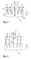
- FIG. 3 shows a plan view of the gate plate 30, whose function in connection will be explained with the figures 4 and 5.
- a block arrow also shows here the direction of the air flow.
- the link plate 30 consists of an im Substantially rectangular plate 31, in which from one longitudinal side guide slots 32a-32e are admitted.
- the course of the guide slots is here symmetrical to the central axis of the guide plate 30, wherein the middle Slot 32c extends in the direction of the central axis, while the left and right adjacent Guide slots 32a, 32b and 32d, 32e inclined at an angle run to the central axis.
- the course of the guide slots 32a-32e depending on the desired alignment behavior of the vanes However, also be set differently.
- the edge-side openings of the Guide slots 32a-32e are each constrictions 33 are formed, which a Passage of the pins 25 of the vanes 20 only against a certain resistance allow.
- the vanes used against the resistance of the constrictions 33 during assembly become.
- the guide slots can also be formed closed be, if all parts in an injection molding step (one-shot method) produced are.
- FIG 4 is a plan view of the cam plate 30 and the vanes 20a-20e shown in accordance with their assembled state, wherein the pins 25 in the housing frame 10 mounted guide vanes 20a-20e each in one of the guide slots 32a-32e intervene. Since the pivot axes 23 of the guide vanes 20 in mounted state, make the vanes in a sliding movement the link plate 30 in the direction of arrow Z is a pivoting movement about the respective pivot axis 23, the extent of which through the course of the guide slots 32a-32e is prescribed. In the advanced shown in Figure 4 Position of the cam plate 30 is doing a divergent orientation the guide vanes 20 assumed, in which this the air flow as possible distribute widely.
- the link plate 30 in its (primary) displacement direction Z adjusted as desired become. This can be done for example by a user by hand or automatically run by an air conditioner.
- Figure 6 shows the assembled vent outlet in perspective in a retracted Position of the link plate according to FIG. 5.
- the recess 24 may also extend over a greater width.
- Such a larger one Width is according to a preferred embodiment of the middle vane 20c realized and serves the engagement of a z. B. on a Lucasleitsteg 11 or 12 of the housing frame 10 attached control element 15th ( Figure 4, 5) to allow.
- the slider 15 engages with a V-shaped approach at the middle vane 20c, so that by its displacement of the rotation angle the vane 20c relative to its pivot axis 23 by the user Can be adjusted as desired.
- the vane decreases 20c then via the link plate 30, the remaining vanes 20a, 20b, 20d, 20e so that they perform a synchronous rotation.
- the cam plate 30 keep the pin 25 their position relative to the guide slots 32a-32e substantially, so that the relative orientation the vanes 20a-20e does not change.
Landscapes
- Physics & Mathematics (AREA)
- Thermal Sciences (AREA)
- Engineering & Computer Science (AREA)
- Mechanical Engineering (AREA)
- Air-Flow Control Members (AREA)
Priority Applications (2)
| Application Number | Priority Date | Filing Date | Title |
|---|---|---|---|
| EP03104607A EP1541395A1 (fr) | 2003-12-09 | 2003-12-09 | Aérateur pour un véhicule |
| CN 200410098379 CN1626372A (zh) | 2003-12-09 | 2004-12-08 | 用于机动车的通风出口 |
Applications Claiming Priority (1)
| Application Number | Priority Date | Filing Date | Title |
|---|---|---|---|
| EP03104607A EP1541395A1 (fr) | 2003-12-09 | 2003-12-09 | Aérateur pour un véhicule |
Publications (1)
| Publication Number | Publication Date |
|---|---|
| EP1541395A1 true EP1541395A1 (fr) | 2005-06-15 |
Family
ID=34486379
Family Applications (1)
| Application Number | Title | Priority Date | Filing Date |
|---|---|---|---|
| EP03104607A Withdrawn EP1541395A1 (fr) | 2003-12-09 | 2003-12-09 | Aérateur pour un véhicule |
Country Status (2)
| Country | Link |
|---|---|
| EP (1) | EP1541395A1 (fr) |
| CN (1) | CN1626372A (fr) |
Cited By (9)
| Publication number | Priority date | Publication date | Assignee | Title |
|---|---|---|---|---|
| DE102005037748B3 (de) * | 2005-08-10 | 2007-02-08 | Dr. Schneider Engineering Gmbh | Luftdüse |
| ES2282007A1 (es) * | 2005-04-25 | 2007-10-01 | Maier, S.Coop | Sistema aireador con fachada provista de listones. |
| FR2901739A1 (fr) * | 2006-06-01 | 2007-12-07 | Coutier Moulage Gen Ind | "aerateur a plusieurs modes de diffusion pour vehicule automobile" |
| DE102007034108B3 (de) * | 2007-07-21 | 2008-08-14 | Dr. Schneider Kunststoffwerke Gmbh | Luftdüse |
| DE102011115178A1 (de) * | 2011-09-28 | 2013-03-28 | Audi Ag | Luftausströmer eines Lüftungs- und Heizungsmoduls für Kraftfahrzeuge mit einer Umschaltung zwischen einer Spotstellung und einer Diffusstellung |
| JP2018099909A (ja) * | 2016-12-19 | 2018-06-28 | しげる工業株式会社 | 車両用レジスタ装置 |
| IT202000023251A1 (it) * | 2020-10-02 | 2022-04-02 | GALIANO Srl | Diffusore per condizionatore d’aria. |
| FR3132052A1 (fr) * | 2022-01-26 | 2023-07-28 | Psa Automobiles Sa | Aérateur de type frontal pour véhicule automobile |
| CN118124343A (zh) * | 2024-05-06 | 2024-06-04 | 宁波继峰汽车零部件股份有限公司 | 一种出风口总成 |
Families Citing this family (7)
| Publication number | Priority date | Publication date | Assignee | Title |
|---|---|---|---|---|
| DE102013109934B3 (de) * | 2013-09-10 | 2014-11-20 | Trw Automotive Electronics & Components Gmbh | Bedienelement und Baugruppe für einen Luftausströmer sowie Verfahren zur Montage eines Bedienelements |
| DE102014116506B4 (de) * | 2014-11-12 | 2018-05-30 | Illinois Tool Works Inc. (N.D.Ges.D. Staates Delaware) | Luftausströmer |
| DE202016103388U1 (de) * | 2016-06-27 | 2016-07-06 | GRAMMER Interior Components GmbH | Luftausströmer |
| CN107571719A (zh) * | 2016-07-05 | 2018-01-12 | 天津市江源塑胶制品有限公司 | 一种汽车空调出风引导装置 |
| DE102017120208B3 (de) * | 2017-09-01 | 2018-06-28 | GRAMMER Interior Components GmbH | Luftausströmer für Fahrzeuginnenräume |
| CN108716482A (zh) * | 2018-05-16 | 2018-10-30 | 广东美的环境电器制造有限公司 | 导风叶调节机构和塔扇 |
| CN113043837B (zh) * | 2019-12-27 | 2022-11-22 | 广州法雷奥发动机冷却有限公司 | 一种主动进气格栅组件和车辆前端模块 |
Citations (5)
| Publication number | Priority date | Publication date | Assignee | Title |
|---|---|---|---|---|
| DE3719835A1 (de) * | 1987-06-13 | 1988-12-22 | Daimler Benz Ag | Jalousieduese zur belueftung eines kraftfahrzeuginnenraumes |
| US5063833A (en) | 1988-09-26 | 1991-11-12 | Nissan Motor Co., Ltd. | Air spout device for a ventilating arrangement |
| FR2710879A1 (fr) * | 1993-10-06 | 1995-04-14 | Peugeot | Aérateur perfectionné, notamment pour planche de bord de véhicule automobile. |
| US5690550A (en) * | 1996-04-24 | 1997-11-25 | Manchester Plastics, Inc. | Diffuser outlet assembly |
| US6059653A (en) * | 1998-12-28 | 2000-05-09 | Collins & Aikman Plastics, Inc. | Air outlet assembly having controllable effort generation |
-
2003
- 2003-12-09 EP EP03104607A patent/EP1541395A1/fr not_active Withdrawn
-
2004
- 2004-12-08 CN CN 200410098379 patent/CN1626372A/zh active Pending
Patent Citations (5)
| Publication number | Priority date | Publication date | Assignee | Title |
|---|---|---|---|---|
| DE3719835A1 (de) * | 1987-06-13 | 1988-12-22 | Daimler Benz Ag | Jalousieduese zur belueftung eines kraftfahrzeuginnenraumes |
| US5063833A (en) | 1988-09-26 | 1991-11-12 | Nissan Motor Co., Ltd. | Air spout device for a ventilating arrangement |
| FR2710879A1 (fr) * | 1993-10-06 | 1995-04-14 | Peugeot | Aérateur perfectionné, notamment pour planche de bord de véhicule automobile. |
| US5690550A (en) * | 1996-04-24 | 1997-11-25 | Manchester Plastics, Inc. | Diffuser outlet assembly |
| US6059653A (en) * | 1998-12-28 | 2000-05-09 | Collins & Aikman Plastics, Inc. | Air outlet assembly having controllable effort generation |
Cited By (11)
| Publication number | Priority date | Publication date | Assignee | Title |
|---|---|---|---|---|
| ES2282007A1 (es) * | 2005-04-25 | 2007-10-01 | Maier, S.Coop | Sistema aireador con fachada provista de listones. |
| DE102005037748B3 (de) * | 2005-08-10 | 2007-02-08 | Dr. Schneider Engineering Gmbh | Luftdüse |
| FR2901739A1 (fr) * | 2006-06-01 | 2007-12-07 | Coutier Moulage Gen Ind | "aerateur a plusieurs modes de diffusion pour vehicule automobile" |
| DE102007034108B3 (de) * | 2007-07-21 | 2008-08-14 | Dr. Schneider Kunststoffwerke Gmbh | Luftdüse |
| DE102011115178A1 (de) * | 2011-09-28 | 2013-03-28 | Audi Ag | Luftausströmer eines Lüftungs- und Heizungsmoduls für Kraftfahrzeuge mit einer Umschaltung zwischen einer Spotstellung und einer Diffusstellung |
| DE102011115178B4 (de) * | 2011-09-28 | 2014-10-09 | Audi Ag | Luftausströmer eines Lüftungs- und Heizungsmoduls für Kraftfahrzeuge mit einer Umschaltung zwischen einer Spotstellung und einer Diffusstellung |
| US9878596B2 (en) | 2011-09-28 | 2018-01-30 | Audi Ag | Air vent of a ventilation and heating module for motor vehicles with switching between a spot position and a diffuse position |
| JP2018099909A (ja) * | 2016-12-19 | 2018-06-28 | しげる工業株式会社 | 車両用レジスタ装置 |
| IT202000023251A1 (it) * | 2020-10-02 | 2022-04-02 | GALIANO Srl | Diffusore per condizionatore d’aria. |
| FR3132052A1 (fr) * | 2022-01-26 | 2023-07-28 | Psa Automobiles Sa | Aérateur de type frontal pour véhicule automobile |
| CN118124343A (zh) * | 2024-05-06 | 2024-06-04 | 宁波继峰汽车零部件股份有限公司 | 一种出风口总成 |
Also Published As
| Publication number | Publication date |
|---|---|
| CN1626372A (zh) | 2005-06-15 |
Similar Documents
| Publication | Publication Date | Title |
|---|---|---|
| EP2760685B1 (fr) | Diffuseur d'air d'un module de ventilation et de chauffage de véhicules automobiles, pouvant changer de position entre une position de focalisation et une position de diffusion | |
| EP1541395A1 (fr) | Aérateur pour un véhicule | |
| DE2736393C2 (de) | Einstellbares Zapfenlager für einen Fensterflügel in einem Stützrahmen | |
| EP1408733B1 (fr) | Dispositif servant a ajuster la largeur d'ouverture du tamis de moissonneuses-batteuses | |
| DE9010872U1 (de) | Gelenkverbindung für Möbelstücke | |
| WO2015158486A2 (fr) | Dispositif de réglage de lames pivotantes d'un aérateur | |
| EP1433630A2 (fr) | Système d'actionnement de lamelles, notamment pour diffuseur d'air | |
| EP2243647B1 (fr) | Aérateur destiné à l'utilisation dans des véhicules automobiles | |
| EP1270286B1 (fr) | Dispositif pour diriger l'air, notamment pour un véhicule | |
| DE3244729C2 (fr) | ||
| DE69821452T2 (de) | Konstruktion eines öffnungsfähigen Fahrzeugdaches | |
| DE60030904T2 (de) | Konstruktion eines öffnungsfähigen Fahrzeugdaches | |
| DE3832052A1 (de) | Drallauslass | |
| DE60013372T3 (de) | Konstruktion eines öffnungsfähigen Fahrzeugdaches | |
| EP0757213B1 (fr) | Dispositif de fermeture pour un appareil de ventilation | |
| DE102005037748B3 (de) | Luftdüse | |
| DE69309973T2 (de) | Luftaustritt für Kraftfahrzeuge mit Luftleitflächen in modularer Struktur | |
| DE69100147T2 (de) | Luftauslass mit Regelung der Luftstromrichtung, insbesondere für Fahrzeugausrüstung. | |
| EP0074486A1 (fr) | Prise d'air à registre coulissant avec un ventilateur actionné par un moteur | |
| DE3823316C2 (fr) | ||
| DE3806994C2 (de) | Münzsortierer | |
| DE69927757T2 (de) | Führungsmechanismus für Fahrzeugsonnendach bestehend aus mindestens zwei Panelen | |
| DE102005015222B3 (de) | Luftdüse | |
| EP1793180A1 (fr) | Buse d'aération dotée de lamelles horizontales et/ou verticales | |
| DE202016100406U1 (de) | Luftausgangsvorrichtung eines Lüftungssystems für ein Fahrzeug |
Legal Events
| Date | Code | Title | Description |
|---|---|---|---|
| PUAI | Public reference made under article 153(3) epc to a published international application that has entered the european phase |
Free format text: ORIGINAL CODE: 0009012 |
|
| AK | Designated contracting states |
Kind code of ref document: A1 Designated state(s): AT BE BG CH CY CZ DE DK EE ES FI FR GB GR HU IE IT LI LU MC NL PT RO SE SI SK TR |
|
| AX | Request for extension of the european patent |
Extension state: AL LT LV MK |
|
| 17P | Request for examination filed |
Effective date: 20051215 |
|
| AKX | Designation fees paid |
Designated state(s): DE FR GB |
|
| STAA | Information on the status of an ep patent application or granted ep patent |
Free format text: STATUS: THE APPLICATION IS DEEMED TO BE WITHDRAWN |
|
| 18D | Application deemed to be withdrawn |
Effective date: 20060829 |