EP1538367B1 - Assemblage d'un clapet amortisseur à caractéristique progressive - Google Patents
Assemblage d'un clapet amortisseur à caractéristique progressive Download PDFInfo
- Publication number
- EP1538367B1 EP1538367B1 EP20040400060 EP04400060A EP1538367B1 EP 1538367 B1 EP1538367 B1 EP 1538367B1 EP 20040400060 EP20040400060 EP 20040400060 EP 04400060 A EP04400060 A EP 04400060A EP 1538367 B1 EP1538367 B1 EP 1538367B1
- Authority
- EP
- European Patent Office
- Prior art keywords
- damper
- valve
- control slide
- piston
- spring
- Prior art date
- Legal status (The legal status is an assumption and is not a legal conclusion. Google has not performed a legal analysis and makes no representation as to the accuracy of the status listed.)
- Active
Links
Images


Classifications
-
- F—MECHANICAL ENGINEERING; LIGHTING; HEATING; WEAPONS; BLASTING
- F16—ENGINEERING ELEMENTS AND UNITS; GENERAL MEASURES FOR PRODUCING AND MAINTAINING EFFECTIVE FUNCTIONING OF MACHINES OR INSTALLATIONS; THERMAL INSULATION IN GENERAL
- F16F—SPRINGS; SHOCK-ABSORBERS; MEANS FOR DAMPING VIBRATION
- F16F9/00—Springs, vibration-dampers, shock-absorbers, or similarly-constructed movement-dampers using a fluid or the equivalent as damping medium
- F16F9/32—Details
- F16F9/50—Special means providing automatic damping adjustment, i.e. self-adjustment of damping by particular sliding movements of a valve element, other than flexions or displacement of valve discs; Special means providing self-adjustment of spring characteristics
- F16F9/512—Means responsive to load action, i.e. static load on the damper or dynamic fluid pressure changes in the damper, e.g. due to changes in velocity
-
- F—MECHANICAL ENGINEERING; LIGHTING; HEATING; WEAPONS; BLASTING
- F16—ENGINEERING ELEMENTS AND UNITS; GENERAL MEASURES FOR PRODUCING AND MAINTAINING EFFECTIVE FUNCTIONING OF MACHINES OR INSTALLATIONS; THERMAL INSULATION IN GENERAL
- F16F—SPRINGS; SHOCK-ABSORBERS; MEANS FOR DAMPING VIBRATION
- F16F9/00—Springs, vibration-dampers, shock-absorbers, or similarly-constructed movement-dampers using a fluid or the equivalent as damping medium
- F16F9/32—Details
- F16F9/34—Special valve constructions; Shape or construction of throttling passages
- F16F9/348—Throttling passages in the form of annular discs or other plate-like elements which may or may not have a spring action, operating in opposite directions or singly, e.g. annular discs positioned on top of the valve or piston body
- F16F9/3485—Throttling passages in the form of annular discs or other plate-like elements which may or may not have a spring action, operating in opposite directions or singly, e.g. annular discs positioned on top of the valve or piston body characterised by features of supporting elements intended to guide or limit the movement of the annular discs
-
- Y—GENERAL TAGGING OF NEW TECHNOLOGICAL DEVELOPMENTS; GENERAL TAGGING OF CROSS-SECTIONAL TECHNOLOGIES SPANNING OVER SEVERAL SECTIONS OF THE IPC; TECHNICAL SUBJECTS COVERED BY FORMER USPC CROSS-REFERENCE ART COLLECTIONS [XRACs] AND DIGESTS
- Y10—TECHNICAL SUBJECTS COVERED BY FORMER USPC
- Y10T—TECHNICAL SUBJECTS COVERED BY FORMER US CLASSIFICATION
- Y10T137/00—Fluid handling
- Y10T137/8593—Systems
- Y10T137/86493—Multi-way valve unit
- Y10T137/86509—Sequentially progressive opening or closing of plural ports
Definitions
- the invention relates to a Dämpfventil raised according to the preamble of claim 1.
- DE 31 07 517 A1 discloses a vibration damper whose Dämpfventil beautifully comprises two valves which are hydraulically connected in parallel.
- a first damping valve comprising a throttle cross-section, which increases with increasing piston rod speed of a valve body, for. B. an elastic disc, is reduced in dependence on the piston rod speed, so that a progressive Dämpfkraftkennline is achieved.
- a pressure relief valve can be used, which connects the two working spaces of the vibration damper.
- different solutions occur in a solution according to DE 31 07 517 A1.
- the damping force at comparatively low speeds is very small and increases parabolic, so that when driving a rather spongy and inaccurate driving feeling is noticeable.
- Object of the present invention it is to realize a Dämpfventil raised having a Dämpfkraftkennline with a progressively increasing proportion, but in a Kennymie Society corresponding to a normal operation, a vehicle-compatible Dämpfkraftkennline follows.
- the object is achieved in that the spool has a pressurized by the damping medium surface which acts in the closing direction of the spool in dependence on the flow rate of the damping medium.
- the great advantage of the invention is that a conventional damping valve can be used as a basis, the damping force characteristic is tuned to the normal operation and both comfort and safety requirements.
- a damping force characteristic can be achieved in addition at higher suspension speeds, which is independent of the current level position of the wheel and independent of the sub-range of the damping force characteristic of normal operation, so that no loss of comfort can be recorded.
- the spool is arranged in relation to the flow path of the damping medium in series with the damping valve. It closes the inflow or outflow of damping medium at the damping valve, so as to achieve a total of a damping force increase.
- the spool is connected with its pressurized surface to a throttle point, which leads to the first Dämpfventilbaue. This allows a space-saving construction of the entire damping valve can be achieved.
- the throttle point is determined by the outer diameter of the spool.
- the spool is held by a spring in passage position.
- a pressure relief valve is connected in parallel. This allows the achievable damping force of the damping valve to be limited to a defined level.
- the pressure relief valve is formed by a spring disk package that also holds the spool in the forward position. Overall, there is a very flat-building unit.
- the spool is held in the forward position regardless of the biasing force acting on the pressure relief valve. This variant allows greater freedom of design in determining the damping force characteristic.
- the spool is slidably mounted relative to the valve disc of the pressure relief valve.
- the valve disc of the pressure limiting valve is arranged coaxially to the spool.
- the spool is axially supported in the passage position on the valve disc of the pressure relief valve.
- a spring carrier takes on the control slide in the passage position holding spring.
- the damping valve must be made very precise in terms of the desired effect. So that unavoidable manufacturing tolerances do not impair the function, the valve body has a plastically deformable adjustment range.
- the adjustment region of the valve body is formed by a wall thickness reduction.
- the spool is controlled biased in the closed position, wherein depending on the existing manufacturing tolerances, a deformation of the spool takes place and the passage cross section of the throttle point is set.
- the throttle point is determined by an inner wall of a cylinder of a vibration damper.
- This spatial design allows the use of very simple spool components, since the cylinder is usually already designed as a precision component.
- the damping valve device is designed on a piston of a vibration damper.
- the inventive damping valve z. B. run as a bottom valve at a vibration damper, then only the displaced volume of the retracting piston rod would be available for Dämpfkrafterzeugung available.
- the invention according to the damping valve on a piston, for. B. for the insertion direction of the piston executes, then possibly the Dämpfmediumvolumen the entire displaced cylinder cross-section used for Dämpfkraftermaschineung, wherein the cavitation formation is taken in the then increasing space for the certainly rarely occurring case in purchasing.
- the spool affects the Dämpfmediumzu- and effluent on the piston.
- the spool is supported on a piston nut of the piston.
- the entire length of the piston is not extended by the damping valve according to the invention.
- the spring holding the control slide in the passage position is independently of a valve spring biasing the valve body of the first damper valve assembly of the piston-side damper valve.
- the valve spring for the first assembly of the damping valve fixes the damper assembly comprising the assembly to the damping valve.
- the usual spring force of the valve spring tends to be so great that this spring force can bias the spring carrier against the force of the force acting on the spool spring on the piston nut.
- the piston nut of the spring carrier and the spool are braced to form a unit.
- the assembly may be assigned a support ring on which the spool is axially supported. This counteracts a misalignment of the spool in the passage position.
- the support ring is connected to transmit torque to the piston nut and executed with Verdichtwerkmaschinebericht.
- the piston nut has the mounting thread to the piston rod, but the shell surface, on which usually the hexagon profile is executed, is covered by the spring carrier and the spool. With the new variant, the piston nut can be screwed over the support ring.
- a first assembly 10 of a damping valve 12 includes for the retraction movement of the piston into the cylinder, the passage channels 15, the outlet ends on the upper side of the piston 7 of at least one valve disc 17 are at least partially covered in conjunction with a valve spring 19.
- the valve body 29 also two groups of passageways 31; 33 has.
- the passageways 33 are for the Influx of a not shown on the underside of the valve body 29 damping agent filled space in the piston rod remote working space 11 is arranged.
- These passageways 33 are usually covered by a simple check valve in the execution of a disc 35 with a closing spring 37.
- the passageways 33, the disc 35 and the closing spring 37 form a first assembly 16 of the bottom valve 27.
- damping medium volume is displaced by the second assembly 18 of the bottom valve 27 and generates a damping force.
- the first or second assembly 16; 18 correspond to the damping valve 20 on the piston, which merges with increasing flow velocity in a passage position.
- the designed as a bottom valve damper valve device 27 also has an axially movable spool 41, the lower end face 42 may come to rest on the disc 35 of the check valve against a spring 43 in the form of an elastic disc.
- the spring 43 holds the spool 41 in a passage position, wherein the top of the disc 35 of the check valve and the lower end surface 42 of the spool 41 form a first throttle 45.
- the spool 41 has at its outer diameter over a multi-stepped contour, wherein a first shoulder 51 with the inner wall 53 of the cylinder forms a second throttle point 55, at which a significant pressure drop is available.
- the axial extent of the first paragraph is deliberately chosen comparatively short in order to minimize temperature-induced viscosity effects within the second throttle body 55.
- the facing in the direction of the piston rod remote working chamber 11 end face can be used as a pressurized surface 57 which acts on the spool 41 in dependence on the flow velocity within the second throttle body 55 in the closing direction.
- the two throttle bodies 45; 55 are sized so that they do not exert any significant effect on the damping force characteristic of the entire damping valve within the normal operation of the vibration damper.
- the pressure limiting valve 59 is formed in this embodiment of a spring disk package, namely the spring 43 which holds the spool 41 in the forward position and at least one cover plate 61 below the spring 43, wherein the spring 43 has at least one passage cross-section 62 which in normal operation of the damping valve of the cover plate 61 is closed.
- the damping valve device according to the invention may be performed, but it is still very useful to equip the bottom valve with a slide 41.
- the spool 41 is supported indirectly on the piston nut 25 and thus influences the Dämpfmediumzustrom in the piston 7.
- the piston nut carries a spring support 63 with an S-shaped cross section, which receives the spring 43, which biases the spool 41 in the forward direction .
- the spring 43 for the spool 41 is carried out independently of the valve spring 23 for the valve body 21, said valve spring 23 and the control spool 41 comprehensive assembly 22, namely the spring carrier 63 together with the spring 43 and the spool 41 can fix on the piston nut 25, which may still be a support ring 65 may be used.
- a pressure relief valve 59 may be executed, which is formed for example by a cover plate 61 which covers the passage cross-section 62 within the spring carrier 63 depending on the direction.
- the slider In a combined arrangement of the Dämpfventil adopted on the piston and the bottom valve, the slider should take the closed position at a lower flow velocity, the closed position than the slide on the piston, since then can not have the effect that in a closed slide on the piston still a comparatively large cross-section on Bottom valve is available and the volume is pushed out of the piston rod remote working space through the bottom valve. One would leave with it damping force unused.
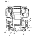
- FIG. 3 shows a modification of FIG. 1.
- the piston nut 25, the spring carrier 63, the spool 41 together with the spring 43 and the support ring 65 form a structural unit.
- the piston nut has a support surface 25s against which the cover plate 61 of the pressure limiting valve 59 rests.
- the inner diameter of the support ring 65 is profiled that upon a plastic deformation of a sleeve portion 25h of the piston nut 25, a projecting end is deformed on the underside of the support ring and in the profiling of the support ring, so that a torque-transmitting connection between the piston nut 25 and the support ring 65 is ,
- the support ring is provided with turning tool surfaces 65v, which make it easier to screw said assembly on the piston rod pin.
- At least one circumferential groove 41 n are incorporated on the inner and outer diameter as wall thickness reduction, which form a plastically deformable adjustment region 44.
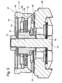
- Fig. 5 shows a further development of the bottom valve 27 of FIG. 1, in which the bias of the cover plates 61 of the pressure limiting valve 59 is independent of the spring 43, which holds the spool 41 in the passage position.
- the spring 43 is designed as a disc spring whose inner diameter range between a bolt 73 and a clamping nut 75 is fixed to the valve body 29. Alternatively, a riveted joint according to FIG. 1 can also be used.
- the disc spring 43 acts on the underside of the locking ring 49.
- the support body 47 serves as a support for the cover plates 61, to which a valve spool 64 independent of the spool valve is pretensioned.
- a pressure ring 77 provides a tensioning chain from the support surface 79 of the support body on the cover plates 61 and the valve disc 64, the pressure ring 77 and the spring 43 to the clamping nut 75.
- the spool 41 is supported in the passage position axially on the underside of the valve disc 64 from . wherein the biasing force is generated by the spring 43.
- the spool 41 between the blocking position, end face 42 rests on the disc 35, and the passage position, spool is axially against the underside of the valve disc 64, slidably mounted to the cover plates 61.
- the bias of the cover plates 61 does not act on the spool so that there is no dependence on the Abhubterrorism the cover plates 61 of the valve disc 64 with respect to the performance of the spool.
Claims (23)
- Assemblage d'un clapet amortisseur, comprenant un premier clapet amortisseur (15; 17; 19; 29; 33; 35; 37) avec une courbe caractéristique de force d'amortissement, selon laquelle un corps de clapet amortisseur (17), dans un premier domaine de fonctionnement en fonction de la vitesse d'écoulement au clapet amortisseur (15; 17; 19; 29; 33; 35; 37), passe à une position de fonctionnement de passage lorsque la vitesse d'écoulement d'un fluide d'amortissement augmente, avec un deuxième clapet amortisseur (41; 55) qui, dans un deuxième domaine de fonctionnement de la courbe caractéristique de la force d'amortissement, présente une caractéristique de force d'amortissement progressive et dont le point d'étranglement (55) peut être amené dans une position de fermeture en liaison avec un coulisseau de commande (41), caractérisé en ce que le coulisseau de commande (41) présente une face (57) exposée à la pression du fluide d'amortissement qui agit sur le coulisseau de commande (41) dans la direction de fermeture en fonction de la vitesse d'écoulement du fluide d'amortissement.
- Assemblage de clapet amortisseur selon la revendication 1, caractérisé en ce que le coulisseau de commande (41) est disposé en série avec le clapet amortisseur (12; 20) par rapport au chemin d'écoulement du fluide d'amortissement.
- Assemblage de clapet amortisseur selon la revendication 1, caractérisé en ce que le coulisseau de commande (41) est raccordé par sa face exposée à la pression (57) à un point d'étranglement (55), qui conduit au premier groupe de clapet amortisseur (15; 17; 19; 31; 39).
- Assemblage de clapet amortisseur selon la revendication 3, caractérisé en ce que le point d'étranglement (55) est déterminé par le diamètre extérieur du coulisseau de commande (41).
- Assemblage de clapet amortisseur selon la revendication 1, caractérisé en ce que le coulisseau de commande (41) est maintenu en position de passage par un ressort (43).
- Assemblage de clapet amortisseur selon la revendication 1, caractérisé en ce qu'un clapet de limitation de pression (59) est monté en parallèle sur le point d'étranglement (45; 55).
- Assemblage de clapet amortisseur selon la revendication 6, caractérisé en ce que le clapet de limitation de pression (59) est formé par un paquet de rondelles élastiques (43; 61), qui maintient également le coulisseau de commande (41) dans la position de passage.
- Clapet amortisseur selon la revendication 6, caractérisé en ce que le coulisseau de commande (41) est maintenu dans la position de passage, indépendamment de la force de précontrainte qui agit sur le clapet de limitation de pression.
- Clapet amortisseur selon la revendication 8, caractérisé en ce que le coulisseau de commande (41) est monté de façon déplaçable par rapport au disque de clapet (64) du clapet de limitation de pression (59).
- Clapet amortisseur selon la revendication 9, caractérisé en ce que le coulisseau de commande (41) s'appuie axialement, en position de passage, sur le disque de clapet (64) du clapet de limitation de pression (59).
- Assemblage de clapet amortisseur selon la revendication 1, caractérisé en ce qu'un support de ressort (63) reçoit le ressort (43) maintenant le coulisseau de commande (41) dans la position de passage.
- Clapet amortisseur selon la revendication 1, caractérisé en ce que le coulisseau de commande (41) comporte une zone de réglage déformable plastiquement (44).
- Clapet amortisseur selon la revendication 12, caractérisé en ce que la zone de réglage (44) du corps de clapet (41) est formée par une diminution de l'épaisseur de paroi (41n).
- Amortisseur de vibrations avec un assemblage de clapet amortisseur selon la revendication 4, caractérisé en ce que le point d'étranglement (55) est déterminé par une paroi intérieure (53) d'un cylindre (3) de l'amortisseur de vibrations (1).
- Amortisseur de vibrations avec un assemblage de clapet amortisseur selon la revendication 1, caractérisé en ce que l'assemblage de clapet amortisseur conforme à l'invention est réalisé sur un piston (7) de l'amortisseur de vibrations (1).
- Amortisseur de vibrations avec un assemblage de clapet amortisseur selon la revendication 5, caractérisé en ce que le coulisseau de commande (41) s'appuie sur un écrou de piston (25) du piston (7).
- Amortisseur de vibrations avec un assemblage de clapet amortisseur selon la revendication 5, caractérisé en ce que le ressort (43) maintenant le coulisseau de commande (41) en position de passage est réalisé indépendamment d'un ressort de clapet (23) exerçant une précontrainte sur le corps de clapet (21) du premier groupe de clapet amortisseur (10) du clapet amortisseur côté piston.
- Assemblage de clapet amortisseur pour un amortisseur de vibrations selon la revendication 7, caractérisé en ce que le ressort de clapet (23) pour le premier groupe (10) du clapet amortisseur (12) fixe le groupe (41; 43; 63) comprenant le coulisseau de commande (41) sur le clapet amortisseur.
- Amortisseur de vibrations avec un clapet amortisseur selon la revendication 6, caractérisé en ce que l'écrou de piston (25) serre le support de ressort (63) et le coulisseau de commande (41) en une unité structurelle.
- Amortisseur de vibrations avec un clapet amortisseur selon la revendication 9, caractérisé en ce que l'unité structurelle (25; 63; 41) est complétée par une bague de support (65), sur laquelle le coulisseau de commande (41) s'appuie axialement.
- Amortisseur de vibrations avec un clapet amortisseur selon la revendication 20, caractérisé en ce que la bague de support (65) est assemblée à l'écrou de piston (25) de façon à transmettre un couple de rotation et est réalisée avec des faces d'application d'un outil de rotation (65v).
- Amortisseur de vibrations avec un assemblage de clapet amortisseur selon la revendication 14, caractérisé en ce que l'assemblage de clapet amortisseur est réalisé sur le piston (7) et sur le clapet de fond (27).
- Amortisseur de vibrations avec un assemblage de clapet amortisseur selon la revendication 22, caractérisé en ce que le coulisseau de commande (41) dans le clapet de fond (27) occupe la position de fermeture pour une vitesse d'écoulement plus basse que le coulisseau de commande (41) sur l'assemblage de clapet amortisseur côté piston.
Applications Claiming Priority (4)
| Application Number | Priority Date | Filing Date | Title |
|---|---|---|---|
| DE10356639 | 2003-12-01 | ||
| DE10356639 | 2003-12-01 | ||
| DE102004050732 | 2004-10-19 | ||
| DE102004050732A DE102004050732A1 (de) | 2003-12-01 | 2004-10-19 | Dämpfventileinrichtung mit progressiver Dämpfkraftkennlinie |
Publications (2)
| Publication Number | Publication Date |
|---|---|
| EP1538367A1 EP1538367A1 (fr) | 2005-06-08 |
| EP1538367B1 true EP1538367B1 (fr) | 2006-07-26 |
Family
ID=34466034
Family Applications (1)
| Application Number | Title | Priority Date | Filing Date |
|---|---|---|---|
| EP20040400060 Active EP1538367B1 (fr) | 2003-12-01 | 2004-11-29 | Assemblage d'un clapet amortisseur à caractéristique progressive |
Country Status (4)
| Country | Link |
|---|---|
| US (1) | US7699148B2 (fr) |
| EP (1) | EP1538367B1 (fr) |
| AT (1) | ATE334323T1 (fr) |
| DE (1) | DE502004001034D1 (fr) |
Cited By (4)
| Publication number | Priority date | Publication date | Assignee | Title |
|---|---|---|---|---|
| EP1925845A1 (fr) | 2006-11-24 | 2008-05-28 | Delphi Technologies, Inc. | Amortisseur hydraulique de suspension |
| DE102008054643B3 (de) * | 2008-12-15 | 2010-09-09 | Zf Friedrichshafen Ag | Schwingungsdämpfer |
| EP2233775A1 (fr) | 2009-03-23 | 2010-09-29 | Delphi Technologies, Inc. | Amortisseur à suspension hydraulique |
| DE102009029059A1 (de) | 2009-03-02 | 2011-03-03 | Zf Friedrichshafen Ag | Fahrwerk mit verstellbarer Dämpfkraft |
Families Citing this family (22)
| Publication number | Priority date | Publication date | Assignee | Title |
|---|---|---|---|---|
| WO2005029269A2 (fr) * | 2003-09-19 | 2005-03-31 | Stanislaw Lewak | Procede et systeme d'entree manuelle de donnees d'utilisateur |
| DE102004054474B3 (de) * | 2004-11-11 | 2006-06-08 | Zf Friedrichshafen Ag | Schwingungsdämpfer mit verstellbarer Dämpfkraft |
| DE102005046276B3 (de) * | 2005-09-27 | 2007-06-14 | Thyssenkrupp Bilstein Suspension Gmbh | Dämpfventileinrichtung mit progressivem Dämpfkraftverlauf |
| DE102005048949B3 (de) * | 2005-10-13 | 2006-12-14 | Zf Friedrichshafen Ag | Schwingungsdämpfer mit verstellbarer Dämpfkraft |
| JP4987283B2 (ja) | 2005-11-09 | 2012-07-25 | カヤバ工業株式会社 | 緩衝器のバルブ構造および緩衝器 |
| JP4883695B2 (ja) * | 2006-09-07 | 2012-02-22 | カヤバ工業株式会社 | 緩衝器のバルブ構造 |
| JP2008082491A (ja) | 2006-09-28 | 2008-04-10 | Kayaba Ind Co Ltd | 緩衝器のバルブ構造 |
| JP5284595B2 (ja) * | 2006-09-28 | 2013-09-11 | カヤバ工業株式会社 | 緩衝器のバルブ構造 |
| JP5226221B2 (ja) * | 2006-09-28 | 2013-07-03 | カヤバ工業株式会社 | 緩衝器のバルブ構造 |
| JP4987460B2 (ja) * | 2006-12-26 | 2012-07-25 | カヤバ工業株式会社 | 緩衝器のバルブ構造 |
| ATE467066T1 (de) * | 2007-02-13 | 2010-05-15 | Delphi Tech Inc | VERFAHREN ZUR VERNICHTUNG VON STOSSBELASTUNGEN HYDRAULISCHER STOßDÄMPFER |
| US8083039B2 (en) * | 2007-08-29 | 2011-12-27 | Tenneco Automotive Operating Company, Inc. | Disc spring intake |
| JP4761474B2 (ja) * | 2007-09-06 | 2011-08-31 | カヤバ工業株式会社 | 緩衝器のバルブ構造 |
| GB0811611D0 (en) | 2008-05-02 | 2008-07-30 | Delphi Tech Inc | Hydraulic damper with compensation chamber |
| US8297418B2 (en) * | 2008-06-05 | 2012-10-30 | Tenneco Automotive Operating Company Inc. | Nested check high speed valve |
| EP2304325B1 (fr) * | 2008-07-25 | 2017-04-05 | Belimo Holding AG | Procédé d'égalisation et de réglage hydrauliques d'une installation de chauffage ou de refroidissement et soupape d'égalisation et de réglage correspondante |
| US9638280B2 (en) | 2013-08-26 | 2017-05-02 | Tenneco Automotive Operating Company Inc. | Shock absorber with frequency dependent passive valve |
| US9500255B2 (en) * | 2014-02-28 | 2016-11-22 | Tenneco Automotive Operating Company Inc. | Shock absorber with frequency dependent passive valve |
| DE102015220707B4 (de) * | 2015-10-23 | 2022-06-02 | Zf Friedrichshafen Ag | Steueranordnung für eine frequenzabhängige Dämpfventileinrichtung eines Schwingungsdämpfers, sowie Verfahren zur plastischen Verformung des Topfbodens der Steueranordnung. |
| DE102016217112B4 (de) * | 2016-09-08 | 2022-10-06 | Zf Friedrichshafen Ag | Frequenzabhängige Dämpfventilanordnung |
| DE102017211614A1 (de) * | 2017-07-07 | 2019-01-10 | Zf Friedrichshafen Ag | Dämpfventil für einen Schwingungsdämpfer |
| CN110259870A (zh) * | 2019-06-28 | 2019-09-20 | 杭州金士顿实业有限公司 | 用于座椅阻尼器的安全阀及其工作方法 |
Family Cites Families (22)
| Publication number | Priority date | Publication date | Assignee | Title |
|---|---|---|---|---|
| FR2070461A5 (fr) | 1969-12-05 | 1971-09-10 | Martin Claude | |
| DE2721933C3 (de) | 1977-05-14 | 1981-06-11 | Boge Gmbh, 5208 Eitorf | Geschwindigkeitsabhängig blockierende Ventileinrichtung, insbesondere für hydraulische Teleskopschwingungsdämpfer von Kraftfahrzeugen |
| JPS56120841A (en) | 1980-02-27 | 1981-09-22 | Nissan Motor Co Ltd | Shock absorber |
| DE3015596A1 (de) * | 1980-04-23 | 1981-10-29 | Fichtel & Sachs Ag, 8720 Schweinfurt | Hydraulischer schwingungsdaempfer mit geraeuscharmen daempfventilen |
| DE3120016A1 (de) * | 1981-05-20 | 1982-12-09 | Stabilus Gmbh, 5400 Koblenz | Stossdaempfer mit geschwindigkeitsabhaengig wirkender daempfeinrichtung |
| DE3533386C2 (de) * | 1985-09-19 | 1994-05-11 | Fichtel & Sachs Ag | Zweirohrschwingungsdämpfer mit federbeaufschlagtem, hydraulischem Druckanschlag |
| US4782925A (en) * | 1986-01-25 | 1988-11-08 | Fichtel & Sachs Ag | Double-tube vibration damper |
| DE3923512A1 (de) * | 1989-07-15 | 1991-01-24 | Stabilus Gmbh | Daempfventil mit stark progressiv verlaufender daempfkraftkennlinie, insbesondere fuer lenkungsdaempfer fuer motorraeder |
| US5261448A (en) * | 1989-11-16 | 1993-11-16 | Atsugi Unisia Corp. | Vibration mode responsive variable damping force shock absorber with feature of automatic selection of damping mode depending upon vibration mode of vehicular body |
| US5129488A (en) | 1989-11-16 | 1992-07-14 | Atsugi Unisia Corporation | Vibration mode responsive variable damping force shock absorber with feature of automatic selection of damping mode depending upon vibration mode of vehicular body |
| JP3062578B2 (ja) * | 1992-04-08 | 2000-07-10 | ヤマハ発動機株式会社 | 油圧緩衝器のベースバルブ取付構造 |
| DE4238728A1 (de) | 1992-11-17 | 1994-05-19 | Stabilus Gmbh | Schwingungsdämpfer mit geschwindigkeitsabhängiger Veränderung der Dämpfungskraft |
| JPH07167191A (ja) | 1993-12-15 | 1995-07-04 | Tokico Ltd | 油圧緩衝器 |
| DE19604721A1 (de) | 1995-02-10 | 1996-08-14 | New Joules Engineering Sales P | Stoßdämpfer für eine Gleisbremse |
| DE19642837C1 (de) | 1996-10-17 | 1998-01-29 | Daimler Benz Ag | Dämpferventil |
| US5823306A (en) * | 1996-11-12 | 1998-10-20 | Tenneco Automotive Inc. | Stroke dependent damping |
| WO2000052354A1 (fr) | 1999-03-03 | 2000-09-08 | Robert Preston | Appareil resistant a un tete-a-queue |
| US6220409B1 (en) | 1999-05-06 | 2001-04-24 | Tenneco Automotive Inc. | Stroke dependent bypass |
| WO2001059325A1 (fr) * | 2000-02-08 | 2001-08-16 | Gabriel Ride Control Products, Inc. | Amortisseur ameliore |
| DE10041199C1 (de) * | 2000-08-23 | 2001-11-29 | Mannesmann Sachs Ag | Schwingungsdämpfer |
| NL1019313C2 (nl) * | 2001-11-06 | 2003-05-12 | Koni Bv | Schokdemper met frequentie afhankelijke demping. |
| CN1656325A (zh) * | 2002-05-29 | 2005-08-17 | 进取悬浮公司 | 具有压力调节控制阀和远程压力调整的液压阻尼器 |
-
2004
- 2004-11-29 DE DE200450001034 patent/DE502004001034D1/de active Active
- 2004-11-29 EP EP20040400060 patent/EP1538367B1/fr active Active
- 2004-11-29 AT AT04400060T patent/ATE334323T1/de not_active IP Right Cessation
- 2004-12-01 US US11/001,470 patent/US7699148B2/en not_active Expired - Fee Related
Cited By (4)
| Publication number | Priority date | Publication date | Assignee | Title |
|---|---|---|---|---|
| EP1925845A1 (fr) | 2006-11-24 | 2008-05-28 | Delphi Technologies, Inc. | Amortisseur hydraulique de suspension |
| DE102008054643B3 (de) * | 2008-12-15 | 2010-09-09 | Zf Friedrichshafen Ag | Schwingungsdämpfer |
| DE102009029059A1 (de) | 2009-03-02 | 2011-03-03 | Zf Friedrichshafen Ag | Fahrwerk mit verstellbarer Dämpfkraft |
| EP2233775A1 (fr) | 2009-03-23 | 2010-09-29 | Delphi Technologies, Inc. | Amortisseur à suspension hydraulique |
Also Published As
| Publication number | Publication date |
|---|---|
| EP1538367A1 (fr) | 2005-06-08 |
| US7699148B2 (en) | 2010-04-20 |
| US20050115786A1 (en) | 2005-06-02 |
| DE502004001034D1 (de) | 2006-09-07 |
| ATE334323T1 (de) | 2006-08-15 |
Similar Documents
| Publication | Publication Date | Title |
|---|---|---|
| EP1538367B1 (fr) | Assemblage d'un clapet amortisseur à caractéristique progressive | |
| DE102005046276B3 (de) | Dämpfventileinrichtung mit progressivem Dämpfkraftverlauf | |
| DE4019221C2 (de) | Stoßdämpfer mit variabler Dämpfungskraft | |
| DE3914297C2 (fr) | ||
| EP2255103B1 (fr) | Amortisseur de vibrations comportant une soupape attachée au tube d'amortisseur | |
| DE19755994C2 (de) | Kolben für einen hydraulischen Schwingungsdämpfer | |
| DE19801055C1 (de) | Hydropneumatische Feder | |
| EP2129538A1 (fr) | Ensemble ressort à rigidité de suspension variable et jambe de force dotée d'un ensemble ressort de ce type | |
| DE10360140A1 (de) | Dämpfungsvorrichtung für ein Kraftfahrzeug | |
| EP1152166A1 (fr) | Amortisseur de chocs avec amortissement dépendant de l'amplitude | |
| WO2005124185A1 (fr) | Systeme d'amortissement ou de freinage de pieces mobiles de meubles | |
| DE2825524C2 (fr) | ||
| DE19642837C1 (de) | Dämpferventil | |
| WO2015185274A1 (fr) | Système de soupapes d'amortissement fonction de la fréquence | |
| DE102010022286A1 (de) | Luftdämpfungsmechanismus für einen Pneumatikzylinder | |
| DE102004050732A1 (de) | Dämpfventileinrichtung mit progressiver Dämpfkraftkennlinie | |
| DE102007057574B3 (de) | Feder-Dämpfer-Einheit eines Druckstöße dämpfenden Stoßreduzierelements, insbesondere für Schienenfahrzeuge | |
| WO2018103982A1 (fr) | Butée de fin de course pour amortisseur de vibrations | |
| EP1431608A2 (fr) | Amortisseur de vibrations avec une force d'amortissement proportionnelle à l'amplitude | |
| DE102004015448B3 (de) | Schwingungsdämpfer | |
| EP1584502B1 (fr) | Dispositif de suspension et d'amortissement pour véhicules motorisés | |
| WO2014122318A1 (fr) | Amortisseur ayant une caractéristique d'amortissement auto-adaptative | |
| DE102017216662A1 (de) | Dämpfungsanordnung für einen Schwingungsdämpfer eines Kraftfahrzeugs | |
| DE3500101C1 (de) | Hydraulischer Zweirohr-Schwingungsdämpfer | |
| EP1705398B1 (fr) | Amortisseur de chocs |
Legal Events
| Date | Code | Title | Description |
|---|---|---|---|
| PUAI | Public reference made under article 153(3) epc to a published international application that has entered the european phase |
Free format text: ORIGINAL CODE: 0009012 |
|
| 17P | Request for examination filed |
Effective date: 20050408 |
|
| AK | Designated contracting states |
Kind code of ref document: A1 Designated state(s): AT BE BG CH CY CZ DE DK EE ES FI FR GB GR HU IE IS IT LI LU MC NL PL PT RO SE SI SK TR |
|
| AX | Request for extension of the european patent |
Extension state: AL HR LT LV MK YU |
|
| GRAP | Despatch of communication of intention to grant a patent |
Free format text: ORIGINAL CODE: EPIDOSNIGR1 |
|
| AKX | Designation fees paid |
Designated state(s): AT BE BG CH CY CZ DE DK EE ES FI FR GB GR HU IE IS IT LI LU MC NL PL PT RO SE SI SK TR |
|
| GRAS | Grant fee paid |
Free format text: ORIGINAL CODE: EPIDOSNIGR3 |
|
| GRAA | (expected) grant |
Free format text: ORIGINAL CODE: 0009210 |
|
| AK | Designated contracting states |
Kind code of ref document: B1 Designated state(s): AT BE BG CH CY CZ DE DK EE ES FI FR GB GR HU IE IS IT LI LU MC NL PL PT RO SE SI SK TR |
|
| PG25 | Lapsed in a contracting state [announced via postgrant information from national office to epo] |
Ref country code: IT Free format text: LAPSE BECAUSE OF FAILURE TO SUBMIT A TRANSLATION OF THE DESCRIPTION OR TO PAY THE FEE WITHIN THE PRESCRIBED TIME-LIMIT;WARNING: LAPSES OF ITALIAN PATENTS WITH EFFECTIVE DATE BEFORE 2007 MAY HAVE OCCURRED AT ANY TIME BEFORE 2007. THE CORRECT EFFECTIVE DATE MAY BE DIFFERENT FROM THE ONE RECORDED. Effective date: 20060726 Ref country code: IE Free format text: LAPSE BECAUSE OF FAILURE TO SUBMIT A TRANSLATION OF THE DESCRIPTION OR TO PAY THE FEE WITHIN THE PRESCRIBED TIME-LIMIT Effective date: 20060726 Ref country code: CZ Free format text: LAPSE BECAUSE OF FAILURE TO SUBMIT A TRANSLATION OF THE DESCRIPTION OR TO PAY THE FEE WITHIN THE PRESCRIBED TIME-LIMIT Effective date: 20060726 Ref country code: IS Free format text: LAPSE BECAUSE OF FAILURE TO SUBMIT A TRANSLATION OF THE DESCRIPTION OR TO PAY THE FEE WITHIN THE PRESCRIBED TIME-LIMIT Effective date: 20060726 Ref country code: SK Free format text: LAPSE BECAUSE OF FAILURE TO SUBMIT A TRANSLATION OF THE DESCRIPTION OR TO PAY THE FEE WITHIN THE PRESCRIBED TIME-LIMIT Effective date: 20060726 Ref country code: PL Free format text: LAPSE BECAUSE OF FAILURE TO SUBMIT A TRANSLATION OF THE DESCRIPTION OR TO PAY THE FEE WITHIN THE PRESCRIBED TIME-LIMIT Effective date: 20060726 Ref country code: RO Free format text: LAPSE BECAUSE OF FAILURE TO SUBMIT A TRANSLATION OF THE DESCRIPTION OR TO PAY THE FEE WITHIN THE PRESCRIBED TIME-LIMIT Effective date: 20060726 Ref country code: NL Free format text: LAPSE BECAUSE OF FAILURE TO SUBMIT A TRANSLATION OF THE DESCRIPTION OR TO PAY THE FEE WITHIN THE PRESCRIBED TIME-LIMIT Effective date: 20060726 Ref country code: FI Free format text: LAPSE BECAUSE OF FAILURE TO SUBMIT A TRANSLATION OF THE DESCRIPTION OR TO PAY THE FEE WITHIN THE PRESCRIBED TIME-LIMIT Effective date: 20060726 Ref country code: SI Free format text: LAPSE BECAUSE OF FAILURE TO SUBMIT A TRANSLATION OF THE DESCRIPTION OR TO PAY THE FEE WITHIN THE PRESCRIBED TIME-LIMIT Effective date: 20060726 |
|
| REG | Reference to a national code |
Ref country code: GB Ref legal event code: FG4D Free format text: NOT ENGLISH |
|
| REG | Reference to a national code |
Ref country code: CH Ref legal event code: EP |
|
| REG | Reference to a national code |
Ref country code: IE Ref legal event code: FG4D Free format text: LANGUAGE OF EP DOCUMENT: GERMAN |
|
| REF | Corresponds to: |
Ref document number: 502004001034 Country of ref document: DE Date of ref document: 20060907 Kind code of ref document: P |
|
| PG25 | Lapsed in a contracting state [announced via postgrant information from national office to epo] |
Ref country code: DK Free format text: LAPSE BECAUSE OF FAILURE TO SUBMIT A TRANSLATION OF THE DESCRIPTION OR TO PAY THE FEE WITHIN THE PRESCRIBED TIME-LIMIT Effective date: 20061026 Ref country code: BG Free format text: LAPSE BECAUSE OF FAILURE TO SUBMIT A TRANSLATION OF THE DESCRIPTION OR TO PAY THE FEE WITHIN THE PRESCRIBED TIME-LIMIT Effective date: 20061026 Ref country code: SE Free format text: LAPSE BECAUSE OF FAILURE TO SUBMIT A TRANSLATION OF THE DESCRIPTION OR TO PAY THE FEE WITHIN THE PRESCRIBED TIME-LIMIT Effective date: 20061026 |
|
| PG25 | Lapsed in a contracting state [announced via postgrant information from national office to epo] |
Ref country code: ES Free format text: LAPSE BECAUSE OF FAILURE TO SUBMIT A TRANSLATION OF THE DESCRIPTION OR TO PAY THE FEE WITHIN THE PRESCRIBED TIME-LIMIT Effective date: 20061106 |
|
| GBT | Gb: translation of ep patent filed (gb section 77(6)(a)/1977) |
Effective date: 20061016 |
|
| PG25 | Lapsed in a contracting state [announced via postgrant information from national office to epo] |
Ref country code: MC Free format text: LAPSE BECAUSE OF NON-PAYMENT OF DUE FEES Effective date: 20061130 Ref country code: BE Free format text: LAPSE BECAUSE OF NON-PAYMENT OF DUE FEES Effective date: 20061130 |
|
| PG25 | Lapsed in a contracting state [announced via postgrant information from national office to epo] |
Ref country code: PT Free format text: LAPSE BECAUSE OF FAILURE TO SUBMIT A TRANSLATION OF THE DESCRIPTION OR TO PAY THE FEE WITHIN THE PRESCRIBED TIME-LIMIT Effective date: 20061226 |
|
| NLV1 | Nl: lapsed or annulled due to failure to fulfill the requirements of art. 29p and 29m of the patents act | ||
| ET | Fr: translation filed | ||
| REG | Reference to a national code |
Ref country code: IE Ref legal event code: FD4D |
|
| PLBI | Opposition filed |
Free format text: ORIGINAL CODE: 0009260 |
|
| PLAX | Notice of opposition and request to file observation + time limit sent |
Free format text: ORIGINAL CODE: EPIDOSNOBS2 |
|
| 26 | Opposition filed |
Opponent name: THYSSENKRUPP BILSTEIN SUSPENSION GMBH Effective date: 20070426 |
|
| PLAF | Information modified related to communication of a notice of opposition and request to file observations + time limit |
Free format text: ORIGINAL CODE: EPIDOSCOBS2 |
|
| PLBB | Reply of patent proprietor to notice(s) of opposition received |
Free format text: ORIGINAL CODE: EPIDOSNOBS3 |
|
| BERE | Be: lapsed |
Owner name: ZF FRIEDRICHSHAFEN A.G. Effective date: 20061130 |
|
| PGFP | Annual fee paid to national office [announced via postgrant information from national office to epo] |
Ref country code: LU Payment date: 20071129 Year of fee payment: 4 |
|
| PG25 | Lapsed in a contracting state [announced via postgrant information from national office to epo] |
Ref country code: AT Free format text: LAPSE BECAUSE OF NON-PAYMENT OF DUE FEES Effective date: 20061129 |
|
| PG25 | Lapsed in a contracting state [announced via postgrant information from national office to epo] |
Ref country code: GR Free format text: LAPSE BECAUSE OF FAILURE TO SUBMIT A TRANSLATION OF THE DESCRIPTION OR TO PAY THE FEE WITHIN THE PRESCRIBED TIME-LIMIT Effective date: 20061027 |
|
| PG25 | Lapsed in a contracting state [announced via postgrant information from national office to epo] |
Ref country code: EE Free format text: LAPSE BECAUSE OF FAILURE TO SUBMIT A TRANSLATION OF THE DESCRIPTION OR TO PAY THE FEE WITHIN THE PRESCRIBED TIME-LIMIT Effective date: 20060726 |
|
| PG25 | Lapsed in a contracting state [announced via postgrant information from national office to epo] |
Ref country code: TR Free format text: LAPSE BECAUSE OF FAILURE TO SUBMIT A TRANSLATION OF THE DESCRIPTION OR TO PAY THE FEE WITHIN THE PRESCRIBED TIME-LIMIT Effective date: 20060726 Ref country code: HU Free format text: LAPSE BECAUSE OF FAILURE TO SUBMIT A TRANSLATION OF THE DESCRIPTION OR TO PAY THE FEE WITHIN THE PRESCRIBED TIME-LIMIT Effective date: 20070127 |
|
| PG25 | Lapsed in a contracting state [announced via postgrant information from national office to epo] |
Ref country code: CY Free format text: LAPSE BECAUSE OF FAILURE TO SUBMIT A TRANSLATION OF THE DESCRIPTION OR TO PAY THE FEE WITHIN THE PRESCRIBED TIME-LIMIT Effective date: 20060726 |
|
| PLCK | Communication despatched that opposition was rejected |
Free format text: ORIGINAL CODE: EPIDOSNREJ1 |
|
| PLBN | Opposition rejected |
Free format text: ORIGINAL CODE: 0009273 |
|
| STAA | Information on the status of an ep patent application or granted ep patent |
Free format text: STATUS: OPPOSITION REJECTED |
|
| 27O | Opposition rejected |
Effective date: 20090202 |
|
| REG | Reference to a national code |
Ref country code: CH Ref legal event code: PL |
|
| GBPC | Gb: european patent ceased through non-payment of renewal fee |
Effective date: 20081129 |
|
| PG25 | Lapsed in a contracting state [announced via postgrant information from national office to epo] |
Ref country code: CH Free format text: LAPSE BECAUSE OF NON-PAYMENT OF DUE FEES Effective date: 20081130 Ref country code: LI Free format text: LAPSE BECAUSE OF NON-PAYMENT OF DUE FEES Effective date: 20081130 |
|
| PG25 | Lapsed in a contracting state [announced via postgrant information from national office to epo] |
Ref country code: GB Free format text: LAPSE BECAUSE OF NON-PAYMENT OF DUE FEES Effective date: 20081129 |
|
| PG25 | Lapsed in a contracting state [announced via postgrant information from national office to epo] |
Ref country code: LU Free format text: LAPSE BECAUSE OF NON-PAYMENT OF DUE FEES Effective date: 20081129 |
|
| PGFP | Annual fee paid to national office [announced via postgrant information from national office to epo] |
Ref country code: FR Payment date: 20121130 Year of fee payment: 9 |
|
| REG | Reference to a national code |
Ref country code: FR Ref legal event code: ST Effective date: 20140731 |
|
| PG25 | Lapsed in a contracting state [announced via postgrant information from national office to epo] |
Ref country code: FR Free format text: LAPSE BECAUSE OF NON-PAYMENT OF DUE FEES Effective date: 20131202 |
|
| PGFP | Annual fee paid to national office [announced via postgrant information from national office to epo] |
Ref country code: DE Payment date: 20191119 Year of fee payment: 16 |
|
| REG | Reference to a national code |
Ref country code: DE Ref legal event code: R119 Ref document number: 502004001034 Country of ref document: DE |
|
| PG25 | Lapsed in a contracting state [announced via postgrant information from national office to epo] |
Ref country code: DE Free format text: LAPSE BECAUSE OF NON-PAYMENT OF DUE FEES Effective date: 20210601 |