EP1538276B1 - Fussbodenpaneel - Google Patents
Fussbodenpaneel Download PDFInfo
- Publication number
- EP1538276B1 EP1538276B1 EP03027873.3A EP03027873A EP1538276B1 EP 1538276 B1 EP1538276 B1 EP 1538276B1 EP 03027873 A EP03027873 A EP 03027873A EP 1538276 B1 EP1538276 B1 EP 1538276B1
- Authority
- EP
- European Patent Office
- Prior art keywords
- panels
- core
- floor
- sides
- recesses
- Prior art date
- Legal status (The legal status is an assumption and is not a legal conclusion. Google has not performed a legal analysis and makes no representation as to the accuracy of the status listed.)
- Expired - Lifetime
Links
- 238000009413 insulation Methods 0.000 claims description 19
- 238000009408 flooring Methods 0.000 claims 4
- 239000011162 core material Substances 0.000 description 20
- 239000002023 wood Substances 0.000 description 10
- 239000000463 material Substances 0.000 description 9
- 230000000694 effects Effects 0.000 description 4
- 239000003292 glue Substances 0.000 description 4
- 239000004033 plastic Substances 0.000 description 4
- 239000005060 rubber Substances 0.000 description 3
- 239000007787 solid Substances 0.000 description 3
- 238000013016 damping Methods 0.000 description 2
- 238000009434 installation Methods 0.000 description 2
- 238000004519 manufacturing process Methods 0.000 description 2
- 239000011159 matrix material Substances 0.000 description 2
- 229920002522 Wood fibre Polymers 0.000 description 1
- 230000001154 acute effect Effects 0.000 description 1
- 239000000853 adhesive Substances 0.000 description 1
- 238000004026 adhesive bonding Methods 0.000 description 1
- 230000001070 adhesive effect Effects 0.000 description 1
- 239000011230 binding agent Substances 0.000 description 1
- 239000002131 composite material Substances 0.000 description 1
- 239000004020 conductor Substances 0.000 description 1
- 238000011109 contamination Methods 0.000 description 1
- 239000007799 cork Substances 0.000 description 1
- 230000001419 dependent effect Effects 0.000 description 1
- 238000011161 development Methods 0.000 description 1
- 230000018109 developmental process Effects 0.000 description 1
- 229910003460 diamond Inorganic materials 0.000 description 1
- 239000010432 diamond Substances 0.000 description 1
- 239000000835 fiber Substances 0.000 description 1
- 239000006260 foam Substances 0.000 description 1
- 239000000203 mixture Substances 0.000 description 1
- 238000012986 modification Methods 0.000 description 1
- 230000004048 modification Effects 0.000 description 1
- 230000001681 protective effect Effects 0.000 description 1
- 230000001603 reducing effect Effects 0.000 description 1
- 239000012858 resilient material Substances 0.000 description 1
- 230000008961 swelling Effects 0.000 description 1
- 239000002025 wood fiber Substances 0.000 description 1
Images


Classifications
-
- E—FIXED CONSTRUCTIONS
- E04—BUILDING
- E04F—FINISHING WORK ON BUILDINGS, e.g. STAIRS, FLOORS
- E04F15/00—Flooring
- E04F15/02—Flooring or floor layers composed of a number of similar elements
-
- E—FIXED CONSTRUCTIONS
- E04—BUILDING
- E04F—FINISHING WORK ON BUILDINGS, e.g. STAIRS, FLOORS
- E04F15/00—Flooring
- E04F15/18—Separately-laid insulating layers; Other additional insulating measures; Floating floors
- E04F15/20—Separately-laid insulating layers; Other additional insulating measures; Floating floors for sound insulation
-
- E—FIXED CONSTRUCTIONS
- E04—BUILDING
- E04F—FINISHING WORK ON BUILDINGS, e.g. STAIRS, FLOORS
- E04F2201/00—Joining sheets or plates or panels
- E04F2201/01—Joining sheets, plates or panels with edges in abutting relationship
- E04F2201/0153—Joining sheets, plates or panels with edges in abutting relationship by rotating the sheets, plates or panels around an axis which is parallel to the abutting edges, possibly combined with a sliding movement
-
- E—FIXED CONSTRUCTIONS
- E04—BUILDING
- E04F—FINISHING WORK ON BUILDINGS, e.g. STAIRS, FLOORS
- E04F2201/00—Joining sheets or plates or panels
- E04F2201/02—Non-undercut connections, e.g. tongue and groove connections
- E04F2201/026—Non-undercut connections, e.g. tongue and groove connections with rabbets, e.g. being stepped
-
- E—FIXED CONSTRUCTIONS
- E04—BUILDING
- E04F—FINISHING WORK ON BUILDINGS, e.g. STAIRS, FLOORS
- E04F2201/00—Joining sheets or plates or panels
- E04F2201/04—Other details of tongues or grooves
- E04F2201/042—Other details of tongues or grooves with grooves positioned on the rear-side of the panel
Definitions
- the invention relates to a floor covering with a plurality of floor panels of the type explained in the preamble of claim 1.
- Such a floor covering is from the JP-A-09088315 known, which describes a floor covering of a plurality of floor panels, which are interconnected via locking elements to form a recess at the bottom. In the bottom, further recesses in the form of slots are provided between the locking elements, which extend into the core material.
- the US 2,088,238 describes a floor covering of individual floor panels, which are provided on its underside with one or more recesses, resulting in further recesses in the assembly of the floor panels.
- these recesses are not designed for a footfall sound insulation, but are filled when laying in the floor covering with adhesive, which forms a good sound bridge.
- JP 2003-147950 describes a floor material with a core (matrix 2) made of a soft plastic material.
- the floor material should have a soundproofing effect, which should be achieved by making the core with a spring rate of sixty degrees or less.
- a plurality of slots are further provided which extend from the back into the matrix.
- FR 2 278 876 describes a connecting device for connecting tiles or sheets of rubber or plastic for a variety of applications.
- the plates are provided on each of two opposite sides with corresponding mechanical locking elements in order to be able to lock adjoining plates to one another.
- the locking elements are designed so that they must fit without recesses in each other, so that no gap between two adjacent plates occurs at the tread. A sound insulation is not addressed.
- DE 33 39 701 describes a sound-absorbing and sound-absorbing panel for forming or covering walls and ceilings.
- the plate consists of a hardened Mixture of fibers and binder and has at its the sound source facing surface on a plurality of holes. The holes are at an acute angle to the surface of the plate.
- Such plates whose holes of the sound source, ie the inside of the room in which they are used, are facing, on the one hand designed for a room sound insulation and on the other hand completely unsuitable for floors, since their openings would clog up immediately with dirt. This affects both the appearance and its effect as a sound conductor breaker.
- U.S. 5,879,781 describes a floor material with sound reducing properties.
- the floor panel in the form of a laminate, has a core made of wood material into which a large number of holes have been made from the bottom side, which are distributed over the entire floor area.
- the holes are covered by a back cover layer and may optionally be filled with materials with high sound damping properties such as rubber, cork, foam or felt.
- the floor laminate includes locking means which in turn are designed so that no gap can form on the bottom side when adjacent laminate panels are correctly connected to each other.
- Known floor panel contains a sound insulation in the form of at least one sound insulation layer, which is arranged on the side facing the side of the kick of the core.
- the sound insulation layer consists of a thin, soft, resilient material, in particular of plastic and must be incorporated in the manufacture of the floor panel in the laminate, which is relatively expensive.
- the WO 99/00242 shows a floor panel in rectangular shape, which contains a core of solid wood and two arranged on the top and bottom of the core, thinner plates, also made of solid wood.
- the floor panel is sound-insulated, wherein in a first embodiment, sound insulation layers between the core and the core on both sides covering plates, with the disadvantages already described, are interposed.
- those sides of the core which face the adjacent, thinner plates are provided with grooves, by means of which the contact surface of wood to wood is reduced, which is intended to effect sound insulation.
- the force-transmitting surface between the layers of wood is reduced, which can lead to flattening of lying between the grooves peaks in floor areas in extreme cases, which are committed particularly strong, so that there slightly lowers the floor.
- longitudinally extending grooves are incorporated in the core, alternately from the top and the bottom, with the grooves extending into this core to over half the thickness of the core.
- these grooves do not extend to the bottom, but are covered by the thinner wood panels, which act as sound bridges.
- the described solid wood floor panels are designed for gluing, wherein the glue layers which extend between the panels also have a sound-damping effect, so that lower requirements must be imposed on additional sound insulation.
- WO 03/087498 describes a floor covering according to the preamble of claims 1 and 2.
- the invention is therefore an object of the invention to provide a floor panel with a simple to produce and effective impact sound insulation.
- Fig. 1 shows a perspective view of a first embodiment of a floor panel 1 according to the invention, which has a tread side 2 and a in Fig. 1 concealed bottom 3, which serves as a support surface on a floor surface, and arranged between the bottom 3 and the tread side 2 core 4.
- the floor panel 1 shown is part of a laminate floor, wherein the tread surface 2 is formed by a laminate layer that is resistant to tread, damage and contamination insensitive and decorative.
- the core 4 consists of an industrially produced wood fiber material, namely an MDF / HDF board.
- the underside 3 is the underside of the core 4 made of the material of the core or may be formed by a protective or leveling layer (not shown here) laminated to the core.
- the floor panel 1 shown here has a rectangular shape and is relatively small, wherein the width B between 5 cm to 15 cm, preferably 8 cm, and the length L between 20 cm and 80 cm, preferably 60 cm.
- the floor panel thus has two opposite long sides 5a and 5b and two opposite short sides 6a and 6b, respectively. At least the long sides 5a, 5b are corresponding, mechanical locking elements 7a and 7b, with which adjacent floor panels can be locked via a snap-in connection.
- the locking element 7a contains for this purpose a bar 8 with a protruding nose 8a, which is bounded by a groove 9 inwards.
- the locking member 7b includes a recess 10 for receiving the strip 8 with an undercut 10a for receiving the nose 8a, which is bounded outwardly by a bar 11 which can be received in the groove 9.
- a bar 11 which can be received in the groove 9.
- adjacent floor panels with their long sides be locked together via a snap or locking connection, wherein it is only necessary to set the two panels with their long sides at an angle to each other so that the nose 8a dips into the recess 10, and then the two panels in alignment and just together to align, causing the nose 8a moves into the undercut 10a.
- the locking elements 7a, 7b in their dimensions, in particular their width b, so matched to one another that the two panels parallel to the short sides 6a can not move against each other.
- the two short sides 6a, 6b are provided with corresponding locking elements 12a, 12b, wherein the locking element 12a corresponds to the locking element 7b and the locking element 12b analogous to the locking element 7a corresponds, but does not have the nose, so that the panels with their short Pages can be connected by simply pressing down, which facilitates the installation.
- connection via the locking elements 7a, 7b and 12a, 12b requires no glue application.
- the floor panel 1 according to the invention is provided with an easily produced and yet effective sound insulation, especially against impact sound, which is provided in the form of at least one recess 13 which extends from the bottom 3 in the panel, the bottom 3 outside the recess 13 flat and is flat.
- the sound insulation is effected in the illustrated embodiment by a single recess 13 which extends in the form of a groove from a short side 6a continuously to the second short side 6b.
- the recess 13 has a depth t, which is dimensioned so that the recess 13 extends from the bottom 3 to over a third to half of the thickness D of the core 4 in this hineinerstreckt.
- the recess 13 is open to the bottom 3 and should remain so. At best, it is possible to apply a thin layer, which does not form a sound bridge, to the underside 3 in such a way that the recess 13 is covered. However, the recess 13 should definitely not lose its sound-wave interrupting function.
- the recess 13 has a width s between 1 and 10 mm and extends approximately in the middle between the long sides 5a, 5b, parallel to them and into the region of the locking elements 12a, 12b of the short sides 6a, 6b. In this case, from the outer strip of the locking element 12a a small connecting web 14 remain standing, which improves the cohesion.
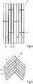
- Fig. 4 shows a part of a floor covering 15, which consists of a plurality of floor panels 1 according to the Fig. 1 to 3 was produced.
- Fig. 4 shows the bottom of the floor covering 15 and a parallel and offset by half each arrangement of the floor panels 1, in the form of a regular ship's floor bandage.
- the locking elements 7a, 7b and 12a, 12b adjacent floor panels are formed so that form on the bottom of the floor covering between adjacent panels grooves 16 between the long sides and grooves 17 between the short sides, while the tread sides 2 adjacent panels almost seamlessly abut each other.
- the grooves 17 serve between adjacent short sides of the impact sound insulation.
- Fig. 5 shows a further embodiment of a floor covering 18 from a further embodiment of inventively embodied floor panels 1 'in herringbone composite, again with a view of the lower sides.
- the recesses in their shape, size (depth, width, length), arrangement and number can be varied.
- two or more continuous recesses may be provided, or a plurality of recesses may be distributed in rows, in a diamond shape, or in another arrangement over the undersides.
- the recesses do not necessarily have to be parallel to the long sides, but can also be arranged along the short sides or randomly.
- the recesses do not necessarily have to be in the form of grooves, but can be designed, for example, as notches, blind holes, cuts or the like.
- the floor panels need not necessarily be provided on all four sides with locking elements, especially in a ship floor laying, for example, it may be sufficient to provide only the long sides with these locking elements.
- the shape and operation of the locking elements can also be changed.
- the invention can be used in floor panels with all common locking systems or to be glued floor panels.
- the invention is also applicable to floor panels of other shapes and dimensions, including standard or standard 120 x 20 cm panels or mitered panels, square or hexagonal or the like.
- the material selection for the floor panel can be adapted to changing uses.
- all embodiments of the floor panels are suitable for all common installation patterns.
Landscapes
- Engineering & Computer Science (AREA)
- Architecture (AREA)
- Civil Engineering (AREA)
- Structural Engineering (AREA)
- Floor Finish (AREA)
Description
- Die Erfindung bezieht sich auf einen Fußbodenbelag mit einer Mehrzahl von Fußbodenpaneelen der im Oberbegriff von Anspruch 1 erläuterten Art.
- Ein derartiger Fußbodenbelag ist aus der
JP-A-09088315 - Die
US 2 088 238 beschreibt einen Fußbodenbelag aus einzelnen Fußbodenpaneelen, die an ihrer Unterseite mit einer oder mehreren Ausnehmungen versehen sind, wobei sich weitere Ausnehmungen beim Zusammenfügen der Fußbodenpaneele ergeben. Diese Ausnehmungen sind jedoch nicht für eine Trittschalldämmung ausgelegt, sondern werden beim Verlegen im Fußbodenbelag mit Kleber verfüllt, der eine gute Schallbrücke bildet. -
JP 2003-147950 -
FR 2 278 876 -
DE 33 39 701 beschreibt eine schalldämmende und schalldämpfende Platte zur Bildung oder zur Verkleidung von Wänden und Decken. Die Platte besteht aus einem erhärteten Gemisch aus Fasern und Bindemittel und weist an ihrer der Schallquelle zugewandten Fläche eine Vielzahl von Löchern auf. Die Löcher verlaufen in einem spitzen Winkel zur Fläche der Platte. Derartige Platten, deren Löcher der Schallquelle, d. h. der Innenseite des Raums, in dem sie verwendet werden, zugewandt sind, sind einerseits für eine Raumschalldämmung ausgelegt und andererseits für Fußböden völlig unbrauchbar, da sich ihre Öffnungen sofort mit Schmutz zusetzen würden. Dies beeinträchtigt sowohl das Erscheinungsbild als auch ihre Wirkung als Schallleitungs-Unterbrecher. -
US 5 879 781 beschreibt ein Fußbodenmaterial mit Schall reduzierenden Eigenschaften. Das Fußbodenpaneel, in Form eines Laminats, hat einen Kern aus Holzmaterial, in den von der Bodenseite her eine Vielzahl von Bohrungen eingebracht wurden, die über die gesamte Bodenfläche verteilt sind. Die Bohrungen werden durch eine rückwärtige Deckschicht abgedeckt und können gegebenenfalls mit Materialien mit hohen Schalldämpfungseigenschaften, wie beispielsweise Gummi, Kork, Schaum oder Filz, gefüllt sein. Das Bodenlaminat enthält Verriegelungseinrichtungen die wiederum so ausgebildet sind, dass sich an der Bodenseite kein Spalt bilden kann, wenn benachbarte Laminatpaneele korrekt mit einander verbunden sind. - Ein aus der
EP 1 264 946 bekanntes Fußbodenpaneel enthält eine Schalldämmung in Form von wenigstens einer Schalldämmschicht, die an der der Trittseite zugewandten Seite des Kerns angeordnet ist. Die Schalldämmschicht besteht aus einem dünnen, weichen, federnd nachgiebigen Material, insbesondere aus Kunststoff und muss bei der Herstellung des Fußbodenpaneels in das Laminat eingearbeitet werden, was relativ aufwendig ist. - Die
WO 99/00242 - In einem weiteren Ausführungsbeispiel sind diejenigen Seiten des Kerns, die den benachbarten, dünneren Platten zugewandt sind, mit Rillen versehen, durch die die Kontaktfläche von Holz zu Holz verringert wird, was eine Schalldämmung bewirken soll. Dadurch wird jedoch auch die kraftübertragende Fläche zwischen den Holzschichten verringert, was im Extremfall zum Abflachen der zwischen den Rillen liegenden Spitzen in Fußbodenbereichen führen kann, die besonders stark begangen werden, so dass sich dort der Fußboden leicht absenkt.
- Weiterhin sind im Kern längsverlaufende Nuten eingearbeitet, und zwar abwechselnd von der Ober- und der Unterseite, wobei sich die Nuten bis über die Hälfte der Dicke des Kerns in diesen Kern hineinerstrecken. Durch diese Nuten soll das Quellen und Schrumpfen des Holzes bei Änderungen der Feuchtigkeit ausgeglichen werden, so dass das sogenannte Arbeiten des Holzes nicht zu Verwerfungen im Fußbodenbelag führt. Diese Nuten erstrecken sich jedoch nicht bis zur Unterseite, sondern sind durch die dünneren Holzplatten abgedeckt, die als Schallbrücken wirken. Außerdem sind die beschriebenen Fußbodenpaneele aus Massivholz für eine Verleimung ausgelegt, wobei die sich zwischen den Paneelen ersteckenden Leimlagen ebenfalls schalldämmend wirken, so dass an eine zusätzliche Schalldämmung geringere Anforderungen zu stellen sind.
- Schließlich ist es gängige Praxis, schallabsorbierende Schichten aus (Nadel-)Filz, Kunststoff, Gummi oder dgl. beim Verlegen unter die Paneele einzubringen oder bei der Herstellung gegebenenfalls mit den Paneelen zu verkleben, was recht aufwändig ist.
-
WO 03/087498 - Der Erfindung liegt somit die Aufgabe zugrunde, ein Fußbodenpaneel mit einer einfach herzustellenden und wirksamen Trittschalldämmung bereitzustellen.
- Die Aufgabe wird durch die in den Ansprüchen 1 und 2 angegebenen Merkmale gelöst.
- Es hat sich herausgestellt, dass es überraschenderweise möglich ist, mit einer einzigen oder einer Reihe hintereinanderliegender, sich von der Unterseite bis in den Kern hineinreichenden Ausnehmungen in Verbindung mit einer durch die Verriegelung selbst gebildeten Ausnehmung eine wirksame Trittschalldämmung zu erreichen, und zwar für Fußbodenpaneele mit mechanischen Verriegelungssystemen, d.h. ohne Leimschicht zwischen den Paneelen. In praktischen Versuchen wurde eine signifikante Reduzierung des Trittschalls um beispielsweise 3dB festgestellt.
- Vorteilhafte Weiterbildungen der Erfindung sind den Unteransprüchen zu entnehmen.
- Ein Ausführungsbeispiel der Erfindung wird nachfolgend anhand der Zeichnungen näher erläutert. Es zeigen:
- Fig. 1
- eine perspektivische Darstellung eines erfindungsgemäßen Fußbodenpaneels,
- Fig. 2
- den Schnitt II-II aus
Fig. 1 , - Fig. 3
- den Schnitt III-III aus
Fig. 1 , - Fig. 4
- einen Teil eines Fußbodenbelags aus den erfindungsgemäßen Fußbodenpaneelen, und
- Fig. 5
- einen Teil eines weiteren Fußbodenbelags aus weiteren erfindungsgemäßen Fußbodenpaneelen.
-
Fig. 1 zeigt in perspektivischer Darstellung ein erstes Ausführungsbeispiel eines erfindungsgemäßen Fußbodenpaneels 1, das eine Trittseite 2 und eine inFig. 1 verdeckte Unterseite 3, die als Auflagefläche auf einem Fußbodenuntergrund dient, sowie einen zwischen der Unterseite 3 und der Trittseite 2 angeordneten Kern 4 aufweist. - Das dargestellte Fußbodenpaneel 1 ist Teil eines Laminatfußbodens, wobei die Trittfläche 2 durch eine Laminatschicht gebildet wird, die trittfest, beschädigungs- und verschmutzungsunempfindlich sowie dekorativ ist. Der Kern 4 besteht aus einem industriell hergestellten Holzfaserwerkstoff, nämlich einer MDF/HDF-Platte . Die Unterseite 3 ist die Unterseite des Kerns 4 aus dem Material des Kerns oder kann durch eine auf den Kern auflaminierte Schutz- oder Ausgleichsschicht (hier nicht gezeichnet) gebildet werden.
- Das hier gezeigte Fußbodenpaneel 1 hat eine rechteckige Form und ist relativ klein, wobei die Breite B zwischen 5 cm bis 15 cm, bevorzugt 8 cm, und die Länge L zwischen 20 cm und 80 cm, bevorzugt 60 cm, beträgt. Das Fußbodenpaneel hat somit zwei gegenüberliegende lange Seiten 5a und 5b sowie zwei gegenüberliegende kurze Seiten 6a bzw. 6b. An wenigstens den langen Seiten 5a, 5b befinden sich korrespondierende, mechanische Verriegelungselemente 7a bzw. 7b, mit denen benachbarte Fußbodenpaneele über eine Rastverbindung verriegelt werden können. Das Verriegelungselement 7a enthält zu diesem Zweck eine Leiste 8 mit einer vorstehenden Nase 8a, die über eine Rille 9 nach innen begrenzt ist. Das Verriegelungselement 7b enthält eine Vertiefung 10 zum Aufnehmen der Leiste 8 mit einer Hinterschneidung 10a zum Aufnehmen der Nase 8a, die nach außen hin durch eine Leiste 11 begrenzt wird, die in der Rille 9 aufgenommen werden kann. Auf diese Weise können benachbarte Fußbodenpaneele mit ihren langen Seiten über eine Schnapp- bzw. Rastverbindung miteinander verriegelt werden, wobei es lediglich erforderlich ist, die beiden Paneele mit ihren langen Seiten im Winkel so aneinander zu setzen, dass die Nase 8a in die Vertiefung 10 eintaucht, und anschließend die beiden Paneele fluchtend und eben miteinander auszurichten, wodurch sich die Nase 8a in die Hinterschneidung 10a bewegt. Dabei sind die Verriegelungselemente 7a, 7b in ihren Abmessungen, insbesondere ihrer Breite b, so aufeinander abgestimmt, dass sich die beiden Paneele parallel zu den kurzen Seiten 6a nicht gegeneinander verschieben können.
- Im dargestellten Ausführungsbeispiel sind auch die beiden kurzen Seiten 6a, 6b mit korrespondierenden Verriegelungselementen 12a, 12b versehen, wobei das Verriegelungselement 12a dem Verriegelungselement 7b entspricht und das Verriegelungselement 12b analog dem Verriegelungselement 7a entspricht, jedoch nicht die Nase aufweist, damit die Paneele mit ihren kurzen Seiten durch einfaches Niederdrücken miteinander verbunden werden können, was die Verlegung erleichtert.
- Die Verbindung über die Verriegelungselemente 7a, 7b und 12a, 12b erfordert keinen Leimauftrag.
- Das erfindungsgemäße Fußbodenpaneel 1 ist mit einer einfach herstellbaren und trotzdem wirksamen Schalldämmung, insbesondere gegen Trittschall, versehen, die in Form wenigstens einer Ausnehmung 13 vorgesehen ist, die sich von der Unterseite 3 in das Paneel hineinerstreckt, wobei die Unterseite 3 außerhalb der Ausnehmung 13 eben und flach ist. Die Schalldämmung wird im dargestellten Ausführungsbeispiel durch eine einzige Ausnehmung 13 bewirkt, die sich in Form einer Nut von einer kurzen Seite 6a durchgehend bis zur zweiten kurzen Seite 6b erstreckt. Die Ausnehmung 13 hat eine Tiefe t, die so bemessen ist, dass sich die Ausnehmung 13 von der Unterseite 3 bis über ein Drittel bis zur Hälfte der Dicke D des Kerns 4 in diesen hineinerstreckt. Die Ausnehmung 13 ist zur Unterseite 3 hin offen und sollte dies auch bleiben. Es ist allenfalls möglich, eine dünne, keine Schallbrücke bildende Schicht auf die Unterseite 3 so aufzubringen, dass die Ausnehmung 13 abgedeckt wird. Die Ausnehmung 13 sollte jedoch auf jeden Fall ihre Schallwellen unterbrechende Funktion nicht einbüßen.
- Die Ausnehmung 13 hat eine Breite s zwischen 1 und 10 mm und erstreckt sich etwa in der Mitte zwischen den langen Seiten 5a, 5b, parallel zu diesen und bis in den Bereich der Verriegelungselemente 12a, 12b der kurzen Seiten 6a, 6b. Dabei kann von der äußeren Leiste des Verriegelungselementes 12a ein kleiner Verbindungssteg 14 stehen bleiben, der den Zusammenhalt verbessert.
-
Fig. 4 zeigt einen Teil eines Fußbodenbelags 15, der aus einer Mehrzahl von Fußbodenpaneelen 1 gemäß denFig. 1 bis 3 hergestellt wurde.Fig. 4 zeigt die Unterseite des Fußbodenbelags 15 und eine parallele und jeweils um die Hälfte versetzte Anordnung der Fußbodenpaneele 1, in Form eines regelmäßigen Schiffsboden-Verbandes. WieFig. 4 zu entnehmen ist, sind die Verriegelungselemente 7a, 7b sowie 12a, 12b benachbarter Fußbodenpaneele so ausgebildet, dass sich auf der Unterseite des Fußbodenbelags zwischen benachbarten Paneelen Nuten 16 zwischen den langen Seiten und Nuten 17 zwischen den kurzen Seiten bilden, während die Trittseiten 2 benachbarter Paneele fast fugenlos aneinander anstoßen. Auf diese Weise werden, bei einer Breite B der Fußbodenpaneele 1 von 8 cm aller 4 cm in Längsrichtung durchlaufende Nuten 13, 16 gebildet, die eine wirksame Trittschalldämmung bieten. Zusätzlich dienen auch die Nuten 17 zwischen benachbarten kurzen Seiten der Trittschalldämmung. -
Fig. 5 zeigt ein weiteres Ausführungsbeispiel eines Fußbodenbelags 18 aus einem weiteren Ausführungsbeispiel von erfindungsgemäß ausgebildeten Fußbodenpaneelen 1' im Fischgrätverbund, wiederum mit Blick auf die Unterseiten 3. - Das Fußbodenpaneel 1' unterscheidet sich vom Fußbodenpaneel 1 lediglich durch eine abweichende Art der Ausnehmung, wobei hier eine Vielzahl einzelner, schlitzförmiger Ausnehmungen 19 in Reihenanordnung hintereinander vorgesehen sind. Ansonsten entspricht die Ausgestaltung des Fußbodenpaneels 1' dem Fußbodenpaneel 1, wobei insbesondere die Reihenanordnung der Ausnehmungen 19 ebenfalls mittig und parallel zwischen den langen Seiten 5a und 5b angeordnet ist und von einer kurzen Seite 6a zur gegenüberliegenden kurzen Seite 6b reicht. Auch bei der Fischgrätanordnung des Bodenbelags 18 bilden sich Nuten 20 zur Trittschalldämmung zwischen den langen und kurzen Seiten.
- Die Erfindung ist durch die Ansprüche bestimmt. Hiernach werden Ausführungsformen beschrieben, welche nicht in dem Schutzbereich der Ansprüche fallen.
- In Abwandlung der beschriebenen und gezeichneten Ausführungsbeispiele können die Ausnehmungen in ihrer Form, Größe (Tiefe, Breite, Länge), Anordnung und Anzahl variiert werden. So können beispielsweise für größere Fußbodenpaneele zwei oder mehr durchlaufende Ausnehmungen vorgesehen sein, oder eine Vielzahl von Ausnehmungen in Reihen, in einer Diamantform oder in einer anderen Anordnung über die Unterseiten verteilt werden. Die Ausnehmungen müssen nicht unbedingt parallel zu den langen Seiten, sondern können auch entlang der kurzen Seiten oder regellos angeordnet sein. Die Ausnehmungen müssen nicht unbedingt als Nuten, sondern können beispielsweise als Kerben, Sacklöcher, Einschnitte oder dgl. ausgebildet sein. Die Fußbodenpaneele müssen nicht unbedingt an allen vier Seiten mit Verriegelungselementen versehen sein, insbesondere bei einer Schiffsboden-Verlegung kann es beispielsweise ausreichen, nur die langen Seiten mit diesen Verriegelungselementen zu versehen. Die Form und Wirkungsweise der Verriegelungselemente kann ebenfalls verändert werden. So kann die Erfindung bei Fußbodenpaneelen mit allen gängigen Verriegelungssystemen oder zu verleimende Fußbodenpaneele eingesetzt werden. Die Erfindung ist weiterhin auf Fußbodenpaneele anderer Formen und Abmessungen anwendbar, einschließlich normal- oder standardgroßer Paneele von 120 x 20 cm oder Paneele mit Gehrungsschnittanschluss, quadratisch oder sechseckig oder dgl.. Auch die Materialauswahl für das Fußbodenpaneel kann an veränderte Einsatzzwecke angepasst werden. Schließlich sind alle Ausführungsbeispiele der Fußbodenpaneele für alle gängigen Verlegungsmuster geeignet.
Claims (4)
- Fußbodenbelag mit einer Mehrzahl von Paneelen (1), die jeweils zwei gegenüber liegende lange Seiten (5a, 5b) und zwei gegenüber liegende kurze Seiten (6a, 6b), korrespondierende, mechanische Verriegelungselemente (7a, 7b; 12a, 12b) an wenigstens zwei Seiten (5a, 5b; 6a, 6b) und einen Kern (4) umfassend eine MDF/HDF-Platte, eine Trittseite (2) umfassend eine trittfeste Laminatschicht, und eine Unterseite (3) aufweisen, wobei die Verriegelungselemente (7a, 7b) an den langen Seiten (5a, 5b) in ihrer Breite (b) so aufeinander abgestimmt sind, dass sich benachbarte Paneele parallel zu den kurzen Seiten nicht gegeneinander verschieben können,
wobei die Paneele ferner mit einer Schalldämmung versehen sind, die von der Unterseite (3) her in den Kern (4) hineinreichende und durch die Verriegelungselemente (7, 12) zwischen benachbarten Paneelen beim Zusammenfügen an der Unterseite (3) gebildete erste Ausnehmungen (16, 17) umfasst, die zur Unterbrechung der Schallfortleitung nach unten hin offen sind,
gekennzeichnet durch
eine einzige zweite Ausnehmung (13), die von einer kurzen Seite (6a) zur gegenüberliegenden kurzen Seite (6b) etwa in der Mitte zwischen den langen Seiten (5a, 5b) durchgehend verläuft und sich von der Unterseite (3) her über ein Drittel bis die Hälfte der Dicke (D) des Kerns (4) in diesen hinein erstreckt und eine Breite (s) von 1 bis 10 mm aufweist. - Fußbodenbelag mit einer Mehrzahl von Paneelen (1'), die jeweils zwei gegenüber liegende lange Seiten (5a, 5b) und zwei gegenüberliegende kurze Seiten (6a, 6b), korrespondierende, mechanische Verriegelungselemente (7a, 7b; 12a, 12b) an wenigstens zwei Seiten (5a, 5b; 6a, 6b) und einen Kern (4) umfassend eine MDF/HDF-Platte, eine Trittseite (2) umfassend eine trittfeste Laminatschicht, und eine Unterseite (3) aufweisen, wobei die Verriegelungselemente (7a, 7b) an den langen Seiten (5a, 5b) in ihrer Breite (b) so aufeinander abgestimmt sind, dass sich benachbarte Paneele parallel zu den kurzen Seiten nicht gegeneinander verschieben können,
wobei die Paneele ferner mit einer Schalldämmung versehen sind, die von der Unterseite (3) her in den Kern (4) hineinreichende und durch die Verriegelungselemente (7, 12) zwischen benachbarten Paneelen beim Zusammenfügen an der Unterseite (3) gebildete erste Ausnehmungen (16, 17) umfasst, die zur Unterbrechung der Schallfortleitung nach unten hin offen sind,
gekennzeichnet durch
eine Vielzahl zueinander beabstandeter zweiter Ausnehmungen (19), die sich von der Unterseite (3) her über ein Drittel bis die Hälfte der Dicke (D) des Kerns (4) in diesen hinein erstrecken und eine Breite (s) von 1 bis 10 mm aufweisen, wobei die Ausnehmungen (19) in einer Reihe angeordnet sind, die von einer kurzen Seite (6a) zur gegenüberliegenden kurzen Seite (6b) etwa in der Mitte zwischen den langen Seiten (5a, 5b) verläuft. - Fußbodenbelag (15), hergestellt aus einer Mehrzahl parallel zueinander verlegter Paneele (1) nach Anspruch 1.
- Fußbodenbelag (18), hergestellt aus einer Mehrzahl im Fischgrätmuster verlegter Paneele (1') nach Anspruch 2.
Priority Applications (4)
| Application Number | Priority Date | Filing Date | Title |
|---|---|---|---|
| EP03027873.3A EP1538276B1 (de) | 2003-12-04 | 2003-12-04 | Fussbodenpaneel |
| ES03027873.3T ES2616862T3 (es) | 2003-12-04 | 2003-12-04 | Panel para suelo |
| US10/991,784 US20050166515A1 (en) | 2003-12-04 | 2004-11-18 | Floor panel |
| PCT/EP2004/013643 WO2005054597A2 (en) | 2003-12-04 | 2004-12-01 | Floor panel |
Applications Claiming Priority (1)
| Application Number | Priority Date | Filing Date | Title |
|---|---|---|---|
| EP03027873.3A EP1538276B1 (de) | 2003-12-04 | 2003-12-04 | Fussbodenpaneel |
Publications (2)
| Publication Number | Publication Date |
|---|---|
| EP1538276A1 EP1538276A1 (de) | 2005-06-08 |
| EP1538276B1 true EP1538276B1 (de) | 2017-02-08 |
Family
ID=34442956
Family Applications (1)
| Application Number | Title | Priority Date | Filing Date |
|---|---|---|---|
| EP03027873.3A Expired - Lifetime EP1538276B1 (de) | 2003-12-04 | 2003-12-04 | Fussbodenpaneel |
Country Status (4)
| Country | Link |
|---|---|
| US (1) | US20050166515A1 (de) |
| EP (1) | EP1538276B1 (de) |
| ES (1) | ES2616862T3 (de) |
| WO (1) | WO2005054597A2 (de) |
Families Citing this family (8)
| Publication number | Priority date | Publication date | Assignee | Title |
|---|---|---|---|---|
| BE1016938A6 (nl) | 2005-03-31 | 2007-10-02 | Flooring Ind Ltd | Werkwijzen voor het vervaardigen en verpakken van vloerpanelen, inrichtingen hierbij aangewend, alsmede vloerpaneel en verpakte set van vloerpanelen. |
| US20130139478A1 (en) | 2005-03-31 | 2013-06-06 | Flooring Industries Limited, Sarl | Methods for packaging floor panels, as well as packed set of floor panels |
| US20070068110A1 (en) * | 2005-09-28 | 2007-03-29 | Bing-Hong Liu | Floor panel with coupling means and methods of making the same |
| DE502005009693D1 (de) * | 2005-12-07 | 2010-07-15 | Berry Finance Nv | Fussbodenpaneel mit einer feuerhemmenden Schicht |
| DE102006007976B4 (de) * | 2006-02-21 | 2007-11-08 | Flooring Technologies Ltd. | Verfahren zur Veredelung einer Bauplatte |
| BE1017157A3 (nl) | 2006-06-02 | 2008-03-04 | Flooring Ind Ltd | Vloerbekleding, vloerelement en werkwijze voor het vervaardigen van vloerelementen. |
| KR101119611B1 (ko) * | 2011-06-01 | 2012-03-06 | 주식회사 대진 | 체결 시공되는 데코타일 |
| BE1024723B1 (nl) * | 2016-11-10 | 2018-06-11 | Ivc Bvba | Vloerpaneel en werkwijze voor het vervaardigen van een vloerpaneel. |
Family Cites Families (18)
| Publication number | Priority date | Publication date | Assignee | Title |
|---|---|---|---|---|
| US2088238A (en) | 1935-06-12 | 1937-07-27 | Harris Mfg Company | Wood flooring |
| US2860385A (en) * | 1956-02-27 | 1958-11-18 | Harold J Cohn | Flooring |
| US3684630A (en) * | 1970-03-09 | 1972-08-15 | Armstrong Cork Co | Cushion floor |
| FR2278876A1 (fr) | 1973-10-09 | 1976-02-13 | Choppe Roger | Procede d'assemblage de dalles divers pour revetement de sol |
| US4449336A (en) * | 1980-06-19 | 1984-05-22 | Kelly Thomas L | Fire barrier reservoir |
| US4416100A (en) * | 1981-09-04 | 1983-11-22 | Troendle, Inc. | Modular wooden floor units and method of manufacture thereof |
| DE3339701A1 (de) | 1983-11-03 | 1985-05-23 | Karl 5249 Hamm Rische | Schalldaemmende und schalldaempfende platte |
| US5103614A (en) * | 1987-05-12 | 1992-04-14 | Eidai Industry Co., Ltd. | Soundproofing woody flooring |
| US5540025A (en) * | 1993-05-29 | 1996-07-30 | Daiken Trade & Industry Co., Ltd. | Flooring material for building |
| JPH0988315A (ja) | 1995-09-26 | 1997-03-31 | Matsushita Electric Works Ltd | 床 材 |
| CA2207633A1 (fr) | 1997-06-26 | 1998-12-26 | Gilles Grenier | Bois resistant aux variations d'humidite |
| US5879781A (en) | 1997-08-20 | 1999-03-09 | The Mead Corporation | Flooring laminate having noise reduction properties |
| JPH11270121A (ja) * | 1998-03-24 | 1999-10-05 | Nippon Paper Industries Co Ltd | 木質直貼り防音床材 |
| US6119423A (en) * | 1998-09-14 | 2000-09-19 | Costantino; John | Apparatus and method for installing hardwood floors |
| SE517183C2 (sv) * | 2000-01-24 | 2002-04-23 | Valinge Aluminium Ab | Låssystem för mekanisk hopfogning av golvskivor, golvskiva försedd med låssystemet och metod för framställning av sådana golvskivor |
| SE522860C2 (sv) * | 2000-03-10 | 2004-03-09 | Pergo Europ Ab | Vertikalt förenade golvelement innefattande en kombination av olika golvelement |
| EP1264946A1 (de) * | 2001-06-05 | 2002-12-11 | Berry Finance Nv | Fussbodenpaneel |
| JP2003147950A (ja) | 2001-11-12 | 2003-05-21 | Matsushita Electric Works Ltd | 防音床材 |
-
2003
- 2003-12-04 ES ES03027873.3T patent/ES2616862T3/es not_active Expired - Lifetime
- 2003-12-04 EP EP03027873.3A patent/EP1538276B1/de not_active Expired - Lifetime
-
2004
- 2004-11-18 US US10/991,784 patent/US20050166515A1/en not_active Abandoned
- 2004-12-01 WO PCT/EP2004/013643 patent/WO2005054597A2/en not_active Ceased
Non-Patent Citations (1)
| Title |
|---|
| None * |
Also Published As
| Publication number | Publication date |
|---|---|
| EP1538276A1 (de) | 2005-06-08 |
| US20050166515A1 (en) | 2005-08-04 |
| WO2005054597A2 (en) | 2005-06-16 |
| WO2005054597A3 (en) | 2007-12-21 |
| ES2616862T3 (es) | 2017-06-14 |
Similar Documents
| Publication | Publication Date | Title |
|---|---|---|
| EP1350904B1 (de) | Fussbodendielen | |
| DE69912950T3 (de) | Bodenplatte | |
| DE69927394T2 (de) | Fussbodensystem mit in vertikaler Richtung zu verbindenen Fussbodenplatten und mit separaten Verbindungsprofilen | |
| DE69926520T2 (de) | Fussbodensystem mit plattenförmigen Fussbodenelementen und separaten Verbindungsprofilen | |
| DE602004011838T2 (de) | Verfahren zur herstellung einer bodenplatte | |
| DE202006020940U1 (de) | Mechanisches Verriegelungssystem für Bodenpaneele | |
| EP1223265A2 (de) | Parkettplatte | |
| CH711305B1 (de) | Fussbodenelement. | |
| DE20222019U1 (de) | Bodenpaneele mit Versiegelung | |
| DE2251762A1 (de) | Fussbodenbelag | |
| EP1524385B1 (de) | Extrudierte Platte, insbesondere für Bodenbelag | |
| EP2227612B1 (de) | Verkleidungspaneel und daraus gebildete verkleidung | |
| DE60312212T2 (de) | Bodenplatte und bodenabdeckung für elastischen boden | |
| DE19538226C2 (de) | Plattenförmiges Trockenestrich-Dämmelement aus Mineralwolle | |
| DE102007054516A1 (de) | Verfahren zum Herstellen einer Bodenbelagsplatte | |
| WO2004018798A2 (de) | Fussboden aus einzelnen elementen | |
| EP1538276A1 (de) | Fussbodenpaneel | |
| DE29609329U1 (de) | Auf einem ebenen Untergrund aufbringbare Folie | |
| DE202008016878U1 (de) | Deckplatte | |
| EP3329066A1 (de) | Wandkonstruktion und verfahren zum montieren | |
| DE102005043721A1 (de) | Fussbodenkonstruktion | |
| WO2009006926A1 (de) | Wandpaneelkonzept 45° | |
| DE20121196U1 (de) | Gebäudeplatte, insbesondere Bodenpaneel | |
| AT405666B (de) | Auf einen ebenen untergrund aufbringbare folie | |
| DE9213183U1 (de) | Verbundplatte mit wenigstens einer Deckschicht aus Holz |
Legal Events
| Date | Code | Title | Description |
|---|---|---|---|
| PUAI | Public reference made under article 153(3) epc to a published international application that has entered the european phase |
Free format text: ORIGINAL CODE: 0009012 |
|
| AK | Designated contracting states |
Kind code of ref document: A1 Designated state(s): AT BE BG CH CY CZ DE DK EE ES FI FR GB GR HU IE IT LI LU MC NL PT RO SE SI SK TR |
|
| AX | Request for extension of the european patent |
Extension state: AL LT LV MK |
|
| 17P | Request for examination filed |
Effective date: 20051207 |
|
| AKX | Designation fees paid |
Designated state(s): AT BE BG CH CY CZ DE DK EE ES FI FR GB GR HU IE IT LI LU MC NL PT RO SE SI SK TR |
|
| GRAP | Despatch of communication of intention to grant a patent |
Free format text: ORIGINAL CODE: EPIDOSNIGR1 |
|
| INTG | Intention to grant announced |
Effective date: 20160512 |
|
| GRAP | Despatch of communication of intention to grant a patent |
Free format text: ORIGINAL CODE: EPIDOSNIGR1 |
|
| INTG | Intention to grant announced |
Effective date: 20160714 |
|
| GRAS | Grant fee paid |
Free format text: ORIGINAL CODE: EPIDOSNIGR3 |
|
| GRAA | (expected) grant |
Free format text: ORIGINAL CODE: 0009210 |
|
| AK | Designated contracting states |
Kind code of ref document: B1 Designated state(s): AT BE BG CH CY CZ DE DK EE ES FI FR GB GR HU IE IT LI LU MC NL PT RO SE SI SK TR |
|
| REG | Reference to a national code |
Ref country code: GB Ref legal event code: FG4D Free format text: NOT ENGLISH |
|
| REG | Reference to a national code |
Ref country code: CH Ref legal event code: EP Ref country code: AT Ref legal event code: REF Ref document number: 866956 Country of ref document: AT Kind code of ref document: T Effective date: 20170215 |
|
| REG | Reference to a national code |
Ref country code: IE Ref legal event code: FG4D Free format text: LANGUAGE OF EP DOCUMENT: GERMAN |
|
| REG | Reference to a national code |
Ref country code: DE Ref legal event code: R096 Ref document number: 50315618 Country of ref document: DE |
|
| REG | Reference to a national code |
Ref country code: SE Ref legal event code: TRGR |
|
| REG | Reference to a national code |
Ref country code: ES Ref legal event code: FG2A Ref document number: 2616862 Country of ref document: ES Kind code of ref document: T3 Effective date: 20170614 Ref country code: NL Ref legal event code: MP Effective date: 20170208 |
|
| PG25 | Lapsed in a contracting state [announced via postgrant information from national office to epo] |
Ref country code: FI Free format text: LAPSE BECAUSE OF FAILURE TO SUBMIT A TRANSLATION OF THE DESCRIPTION OR TO PAY THE FEE WITHIN THE PRESCRIBED TIME-LIMIT Effective date: 20170208 Ref country code: GR Free format text: LAPSE BECAUSE OF FAILURE TO SUBMIT A TRANSLATION OF THE DESCRIPTION OR TO PAY THE FEE WITHIN THE PRESCRIBED TIME-LIMIT Effective date: 20170509 |
|
| PG25 | Lapsed in a contracting state [announced via postgrant information from national office to epo] |
Ref country code: BG Free format text: LAPSE BECAUSE OF FAILURE TO SUBMIT A TRANSLATION OF THE DESCRIPTION OR TO PAY THE FEE WITHIN THE PRESCRIBED TIME-LIMIT Effective date: 20170508 Ref country code: NL Free format text: LAPSE BECAUSE OF FAILURE TO SUBMIT A TRANSLATION OF THE DESCRIPTION OR TO PAY THE FEE WITHIN THE PRESCRIBED TIME-LIMIT Effective date: 20170208 Ref country code: PT Free format text: LAPSE BECAUSE OF FAILURE TO SUBMIT A TRANSLATION OF THE DESCRIPTION OR TO PAY THE FEE WITHIN THE PRESCRIBED TIME-LIMIT Effective date: 20170608 |
|
| PG25 | Lapsed in a contracting state [announced via postgrant information from national office to epo] |
Ref country code: SK Free format text: LAPSE BECAUSE OF FAILURE TO SUBMIT A TRANSLATION OF THE DESCRIPTION OR TO PAY THE FEE WITHIN THE PRESCRIBED TIME-LIMIT Effective date: 20170208 Ref country code: RO Free format text: LAPSE BECAUSE OF FAILURE TO SUBMIT A TRANSLATION OF THE DESCRIPTION OR TO PAY THE FEE WITHIN THE PRESCRIBED TIME-LIMIT Effective date: 20170208 Ref country code: CZ Free format text: LAPSE BECAUSE OF FAILURE TO SUBMIT A TRANSLATION OF THE DESCRIPTION OR TO PAY THE FEE WITHIN THE PRESCRIBED TIME-LIMIT Effective date: 20170208 Ref country code: IT Free format text: LAPSE BECAUSE OF FAILURE TO SUBMIT A TRANSLATION OF THE DESCRIPTION OR TO PAY THE FEE WITHIN THE PRESCRIBED TIME-LIMIT Effective date: 20170208 Ref country code: EE Free format text: LAPSE BECAUSE OF FAILURE TO SUBMIT A TRANSLATION OF THE DESCRIPTION OR TO PAY THE FEE WITHIN THE PRESCRIBED TIME-LIMIT Effective date: 20170208 |
|
| REG | Reference to a national code |
Ref country code: DE Ref legal event code: R097 Ref document number: 50315618 Country of ref document: DE |
|
| PG25 | Lapsed in a contracting state [announced via postgrant information from national office to epo] |
Ref country code: DK Free format text: LAPSE BECAUSE OF FAILURE TO SUBMIT A TRANSLATION OF THE DESCRIPTION OR TO PAY THE FEE WITHIN THE PRESCRIBED TIME-LIMIT Effective date: 20170208 |
|
| PLBE | No opposition filed within time limit |
Free format text: ORIGINAL CODE: 0009261 |
|
| STAA | Information on the status of an ep patent application or granted ep patent |
Free format text: STATUS: NO OPPOSITION FILED WITHIN TIME LIMIT |
|
| 26N | No opposition filed |
Effective date: 20171109 |
|
| REG | Reference to a national code |
Ref country code: FR Ref legal event code: PLFP Year of fee payment: 15 |
|
| PG25 | Lapsed in a contracting state [announced via postgrant information from national office to epo] |
Ref country code: SI Free format text: LAPSE BECAUSE OF FAILURE TO SUBMIT A TRANSLATION OF THE DESCRIPTION OR TO PAY THE FEE WITHIN THE PRESCRIBED TIME-LIMIT Effective date: 20170208 |
|
| REG | Reference to a national code |
Ref country code: CH Ref legal event code: PL |
|
| REG | Reference to a national code |
Ref country code: IE Ref legal event code: MM4A |
|
| PG25 | Lapsed in a contracting state [announced via postgrant information from national office to epo] |
Ref country code: LU Free format text: LAPSE BECAUSE OF NON-PAYMENT OF DUE FEES Effective date: 20171204 |
|
| PG25 | Lapsed in a contracting state [announced via postgrant information from national office to epo] |
Ref country code: IE Free format text: LAPSE BECAUSE OF NON-PAYMENT OF DUE FEES Effective date: 20171204 |
|
| PG25 | Lapsed in a contracting state [announced via postgrant information from national office to epo] |
Ref country code: LI Free format text: LAPSE BECAUSE OF NON-PAYMENT OF DUE FEES Effective date: 20171231 Ref country code: CH Free format text: LAPSE BECAUSE OF NON-PAYMENT OF DUE FEES Effective date: 20171231 |
|
| REG | Reference to a national code |
Ref country code: AT Ref legal event code: MM01 Ref document number: 866956 Country of ref document: AT Kind code of ref document: T Effective date: 20171204 |
|
| PG25 | Lapsed in a contracting state [announced via postgrant information from national office to epo] |
Ref country code: AT Free format text: LAPSE BECAUSE OF NON-PAYMENT OF DUE FEES Effective date: 20171204 |
|
| PG25 | Lapsed in a contracting state [announced via postgrant information from national office to epo] |
Ref country code: MC Free format text: LAPSE BECAUSE OF FAILURE TO SUBMIT A TRANSLATION OF THE DESCRIPTION OR TO PAY THE FEE WITHIN THE PRESCRIBED TIME-LIMIT Effective date: 20170208 Ref country code: HU Free format text: LAPSE BECAUSE OF FAILURE TO SUBMIT A TRANSLATION OF THE DESCRIPTION OR TO PAY THE FEE WITHIN THE PRESCRIBED TIME-LIMIT; INVALID AB INITIO Effective date: 20031204 |
|
| PG25 | Lapsed in a contracting state [announced via postgrant information from national office to epo] |
Ref country code: CY Free format text: LAPSE BECAUSE OF NON-PAYMENT OF DUE FEES Effective date: 20170208 |
|
| PG25 | Lapsed in a contracting state [announced via postgrant information from national office to epo] |
Ref country code: TR Free format text: LAPSE BECAUSE OF FAILURE TO SUBMIT A TRANSLATION OF THE DESCRIPTION OR TO PAY THE FEE WITHIN THE PRESCRIBED TIME-LIMIT Effective date: 20170208 |
|
| PGFP | Annual fee paid to national office [announced via postgrant information from national office to epo] |
Ref country code: FR Payment date: 20211229 Year of fee payment: 19 Ref country code: GB Payment date: 20211229 Year of fee payment: 19 Ref country code: SE Payment date: 20211229 Year of fee payment: 19 Ref country code: DE Payment date: 20211229 Year of fee payment: 19 |
|
| PGFP | Annual fee paid to national office [announced via postgrant information from national office to epo] |
Ref country code: BE Payment date: 20211229 Year of fee payment: 19 |
|
| REG | Reference to a national code |
Ref country code: DE Ref legal event code: R119 Ref document number: 50315618 Country of ref document: DE |
|
| PGFP | Annual fee paid to national office [announced via postgrant information from national office to epo] |
Ref country code: ES Payment date: 20230701 Year of fee payment: 19 |
|
| REG | Reference to a national code |
Ref country code: SE Ref legal event code: EUG |
|
| GBPC | Gb: european patent ceased through non-payment of renewal fee |
Effective date: 20221204 |
|
| REG | Reference to a national code |
Ref country code: BE Ref legal event code: MM Effective date: 20221231 |
|
| PG25 | Lapsed in a contracting state [announced via postgrant information from national office to epo] |
Ref country code: SE Free format text: LAPSE BECAUSE OF NON-PAYMENT OF DUE FEES Effective date: 20221205 Ref country code: GB Free format text: LAPSE BECAUSE OF NON-PAYMENT OF DUE FEES Effective date: 20221204 Ref country code: DE Free format text: LAPSE BECAUSE OF NON-PAYMENT OF DUE FEES Effective date: 20230701 |
|
| PG25 | Lapsed in a contracting state [announced via postgrant information from national office to epo] |
Ref country code: FR Free format text: LAPSE BECAUSE OF NON-PAYMENT OF DUE FEES Effective date: 20221231 Ref country code: BE Free format text: LAPSE BECAUSE OF NON-PAYMENT OF DUE FEES Effective date: 20221231 |
|
| REG | Reference to a national code |
Ref country code: ES Ref legal event code: FD2A Effective date: 20240126 |
|
| PG25 | Lapsed in a contracting state [announced via postgrant information from national office to epo] |
Ref country code: ES Free format text: LAPSE BECAUSE OF NON-PAYMENT OF DUE FEES Effective date: 20221205 |
|
| PG25 | Lapsed in a contracting state [announced via postgrant information from national office to epo] |
Ref country code: ES Free format text: LAPSE BECAUSE OF NON-PAYMENT OF DUE FEES Effective date: 20221205 |