EP1538119B1 - Dispositif pour recevoir une pile auxiliaire pendant l'alimentation en feuilles dans une machine d'imprimerie - Google Patents
Dispositif pour recevoir une pile auxiliaire pendant l'alimentation en feuilles dans une machine d'imprimerie Download PDFInfo
- Publication number
- EP1538119B1 EP1538119B1 EP04105937A EP04105937A EP1538119B1 EP 1538119 B1 EP1538119 B1 EP 1538119B1 EP 04105937 A EP04105937 A EP 04105937A EP 04105937 A EP04105937 A EP 04105937A EP 1538119 B1 EP1538119 B1 EP 1538119B1
- Authority
- EP
- European Patent Office
- Prior art keywords
- fact
- crossbar
- support
- stack
- support elements
- Prior art date
- Legal status (The legal status is an assumption and is not a legal conclusion. Google has not performed a legal analysis and makes no representation as to the accuracy of the status listed.)
- Expired - Lifetime
Links
- 238000007639 printing Methods 0.000 title claims description 12
- 238000006073 displacement reaction Methods 0.000 claims description 2
- 230000005540 biological transmission Effects 0.000 description 6
- 238000007645 offset printing Methods 0.000 description 2
- 239000000725 suspension Substances 0.000 description 2
- 241000252254 Catostomidae Species 0.000 description 1
- 239000000463 material Substances 0.000 description 1
- 230000000284 resting effect Effects 0.000 description 1
Images




Classifications
-
- B—PERFORMING OPERATIONS; TRANSPORTING
- B65—CONVEYING; PACKING; STORING; HANDLING THIN OR FILAMENTARY MATERIAL
- B65H—HANDLING THIN OR FILAMENTARY MATERIAL, e.g. SHEETS, WEBS, CABLES
- B65H1/00—Supports or magazines for piles from which articles are to be separated
- B65H1/26—Supports or magazines for piles from which articles are to be separated with auxiliary supports to facilitate introduction or renewal of the pile
- B65H1/263—Auxiliary supports for keeping the pile in the separation process during introduction of a new pile
-
- B—PERFORMING OPERATIONS; TRANSPORTING
- B65—CONVEYING; PACKING; STORING; HANDLING THIN OR FILAMENTARY MATERIAL
- B65H—HANDLING THIN OR FILAMENTARY MATERIAL, e.g. SHEETS, WEBS, CABLES
- B65H2220/00—Function indicators
- B65H2220/09—Function indicators indicating that several of an entity are present
-
- B—PERFORMING OPERATIONS; TRANSPORTING
- B65—CONVEYING; PACKING; STORING; HANDLING THIN OR FILAMENTARY MATERIAL
- B65H—HANDLING THIN OR FILAMENTARY MATERIAL, e.g. SHEETS, WEBS, CABLES
- B65H2405/00—Parts for holding the handled material
- B65H2405/30—Other features of supports for sheets
- B65H2405/32—Supports for sheets partially insertable - extractable, e.g. upon sliding movement, drawer
- B65H2405/321—Shutter type element, i.e. involving multiple interlinked support elements
-
- B—PERFORMING OPERATIONS; TRANSPORTING
- B65—CONVEYING; PACKING; STORING; HANDLING THIN OR FILAMENTARY MATERIAL
- B65H—HANDLING THIN OR FILAMENTARY MATERIAL, e.g. SHEETS, WEBS, CABLES
- B65H2405/00—Parts for holding the handled material
- B65H2405/30—Other features of supports for sheets
- B65H2405/32—Supports for sheets partially insertable - extractable, e.g. upon sliding movement, drawer
- B65H2405/323—Cantilever finger member, e.g. reciprocating in parallel to plane of handled material
- B65H2405/3231—Cantilever during insertion but supported on both sides of the pile upon full insertion
-
- B—PERFORMING OPERATIONS; TRANSPORTING
- B65—CONVEYING; PACKING; STORING; HANDLING THIN OR FILAMENTARY MATERIAL
- B65H—HANDLING THIN OR FILAMENTARY MATERIAL, e.g. SHEETS, WEBS, CABLES
- B65H2801/00—Application field
- B65H2801/03—Image reproduction devices
- B65H2801/21—Industrial-size printers, e.g. rotary printing press
Definitions
- the invention relates to a device for receiving an auxiliary stack when conveying sheets in a printing machine according to the preamble of claim 1.
- a device for combining a remaining sheet stack and a main sheet pile is described in the feeder of a sheet-fed press.
- the device comprises a support plate for the remaining sheet stack, which has rectangular grooves on its upper side.
- To temporarily carry the rest of the stack rigid, straight, rectangular rods are provided at a distance of the grooves.
- the rods are rigidly attached to a crossbeam.
- the DE 197 38 029 A1 includes a sheet feeder for a printing press with an auxiliary stacking table, in which are arranged parallel to each other and insertable in the plane of a stack rods.
- an elastic rod suspension in the form of a flexible traverse is used. The elastic suspension causes that when removing the auxiliary stacking table from the sheet feeder between the bars a path difference is present.
- a portion of the rods are fixedly secured to a crossbar, while another part of the rods are associated with springs of the crosshead. Each spring is associated with a rod guide in which a rod can slide in the longitudinal direction.
- the crosshead To insert the rods into the grooves, the crosshead is moved by a drive. There are high demands on the dimensions and distances of the grooves and rods and on the positioning system for the traverse. In order to be able to guide the bars as freely as possible into the grooves, a high expenditure on costs and material must be driven.
- the object of the invention is to develop a device for receiving an auxiliary stack when conveying sheets in a printing machine, which allows a reduction of constraining forces in the management of support elements.
- the invention is based on the fact that arranged on a cross member supporting elements for an auxiliary stack in at least two degrees of freedom are hinged to the cross member.
- the invention is particularly advantageously applicable to devices in which articulated links are used as support elements that are movable on a curved path.
- the device requires a small volume.
- the ends of the support members may be secured via joints in recesses of the crossbar.
- the walls of a recess can simultaneously form stops for the movement of a support element.
- a support element can be coupled via a joint with a crossbeam, which allows a movement in four degrees of freedom.
- a universal joint can be provided between the traverse and a support element.
- the support members When a pallet having grooves in which the support members are positioned is used to support a stack, then the support members may be slidably disposed within the crosshead in the direction of movement out of the grooves. In this case, the support elements may have in pairs different border areas for the shift.
- a feeder 1 and a first printing unit 2 of a sheet-fed offset printing machine is shown.
- the printing unit 2 includes an inking unit 3, a dampening unit 4, a forme cylinder 5, a transfer cylinder 6, a printing cylinder 7, a feed cylinder 8 and a transport drum 9.
- the feeder 1 includes a pallet 10, on which a stack 11 is located.
- the pallet 10 is located on a stacking table 12 which is positionable by means of chains 13, 14 of a chain transmission in the vertical direction 15.
- an auxiliary stacking device is provided.
- the auxiliary stacking device consists of a holder 16 for a plurality of parallel arranged support elements 17, a feed device 18 and a guide 19 for the support members 17 and a front support rail 20.
- the holder 16 is connected by means of chains 21 of a chain transmission together with the guide 19 and the feed device 18 in vertical direction can be positioned and by means of a positioning device, not shown in the horizontal direction perpendicular to the plane of the drawing Fig. 1 positionable.
- the support rail 20 can be positioned by means of chains 22 of a chain transmission in the vertical direction 15.
- the pallet 10 has webs and grooves. The stack 11 rests on the webs of the pallet 10. Through the grooves through the support means 17, the support members 17 can be positioned so far that they rest on the support rail 20.
- the stack 11 is guided with the chains 13, 14 corresponding to the printing speed against a suction head 23 with suction pads 24, 25.
- suction pads 24, 25 lead suction air lines 26.
- the suckers 23 are in the horizontal direction 27 reciprocally movable.
- the suction pads 24, 25 are on the stack 11 overhead sheet 28 isolated and promoted by the movement of the sucker 23 on a feeder table 29 against leading 30 marks.
- the sheets 28 are transferred by means of a swing gripper 31 to the feed cylinder 8.
- the sheet 28 is printed.
- the transport drum 9 the transport to other printing units.
- the time for renewing the stack 11 is reached.
- the auxiliary stack 11 is temporarily held on the support elements 17 with a remainder of the sheet 28.
- the holder 16 is positioned with the support members 17 in the vertical and horizontal directions so that the tips 32 of the support members 17 point approximately to the centers of the cross-sectional areas of the pallet grooves.
- the feed device 18 is set with a motor 33 and a gear 34 in operation, so that the attached to a cross member 35 support members 17 pass through the pallet grooves on the support rail 20.
- the support members 17 are made of articulated members 36 which follow outside of the pallet grooves and a guide in the holder 16 of the curved shape of the guide 19.
- the members of the support members 17 are rigid for the load of the auxiliary stack 11.
- the approach of the auxiliary stack 11 to the suction pads 24, 25 is done in the other by vertical drive of the holder 16 and the support rail 20 via the chain transmission on the chains 21, 22. In this case, the auxiliary stack 11 is completely taken up with its weight on the support elements 17.
- the stacking table 12 is lowered with the pallet 10 via the chain drive on the chains 13, 14 until it assumes a lower position for receiving a new main stack.
- the new main stack is brought under the support elements 17 of the auxiliary stack, so that the main stack and auxiliary stack 11 are aligned. Subsequently, the support elements 17 are retracted by means of the feed device 18 in the direction of the guide 19, so that auxiliary stack 11 and the new main stack to a stack 11th unite.
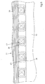
- Fig. 2 shows the support members 17 on the cross member 35.
- the cross member 35 has recesses 37, in which the ends of the support members 17 are attached.
- the support members 17 are retracted in an extended form in grooves 38 of the pallet 10, which is closer in Fig. 3 is shown.
- Both the tips 32 of the support elements 17 and the grooves 38 have chamfers 39, 40th
- FIG. 4 5 two views are shown with details how the cross member 35 is arranged in the guide 19.
- the cross member 35 is guided on both sides with rollers 41, 42 on a roller conveyor 43.
- the cross member 35 is coupled via pins 44, 45 with chains 46, 47.
- the chains 46, 47 slide in the guide 19 and communicate with the gear 34.
- FIGS. 6 and 7 show an articulated connection of a support member 17 to the cross member 35.
- universal joints 48 are arranged in the recesses 37 of the cross member 35.
- the end of the support member 17 is pivotally mounted about the axis of a pin 49.
- the pin 49 is seated on one side of a double-forked connecting piece 50.
- a bolt 55 is provided, the axis of which is parallel to the axis of the pin 49.
- Another pin 51 penetrates the pin 55 in a direction perpendicular to the axis of the pin 49.
- the pin 51 is further held in a bolt 52 with forked ends.
- the cylindrical bolt 52 is rotatably mounted in a bore of the cross member 35.
- a projection 53 of the bolt 52 and a locking ring 54 prevent displacement of the bolt 52 in the axial direction.
- the support member 17 and the connector 50 are pivotable about the axis of the pin 51.
- the pivotal movement of the support member 17 about the axes of the pins 49, 51st and the rotation about the axis of the bolts 52, 55 is limited by the inner walls of the recesses 37.
- FIG. 8 an embodiment is shown in which some of the support members 17 in the cross member 35 have a game x, because the length of the bolt 52 opposite Fig. 6, 7 something is enlarged.
- pulling out begins at support members 17 with clearance x slightly later than support members 17 without play.
- the game x can be provided over the width of an arc 28 in support element pairs 17 symmetrically to the center of the same size.
Landscapes
- Engineering & Computer Science (AREA)
- Mechanical Engineering (AREA)
- Sheets, Magazines, And Separation Thereof (AREA)
- Pile Receivers (AREA)
Claims (9)
- Dispositif pour la réception d'une pile auxiliaire pendant l'alimentation de feuilles dans une machine d'imprimerie,
avec des éléments porteurs disposés sur une traverse pour la pile auxiliaire, caractérisé en ce que
les éléments porteurs (17) sont fixés à la traverse (35) de manière articulée dans au moins deux degrés de liberté. - Dispositif selon la revendication 1, caractérisé en ce que les éléments porteurs (17) se composent d'organes (36) reliés de manière articulée et en ce que la traverse (35) est accouplée de part et d'autres à un entraînement par chaîne (46, 47).
- Dispositif selon la revendication 1, caractérisé en ce que la traverse (35) est mobile sur un rail courbe (19).
- Dispositif selon la revendication 1, caractérisé en ce que la traverse (35) présente des évidements (37) dans lesquels sont prévues des articulations (48) qui sont disposées respectivement entre la traverse (35) et un élément support (17).
- Dispositif selon la revendication 4, caractérisé en ce que des parois d'un évidement (37) forment des butées pour le déplacement d'un élément porteur (17).
- Dispositif selon la revendication 4, caractérisé en ce qu'une articulation (48) permet un déplacement d'un élément porteur (17) dans quatre degrés de liberté.
- Dispositif selon la revendication 1, caractérisé en ce qu'il est prévu une articulation à cardan (48) entre la traverse (35) et un élément porteur (17).
- Dispositif selon la revendication 1, caractérisé en ce que les éléments porteurs (17) sont disposés mobiles dans des limites dans la traverse (35) dans la direction du déplacement depuis des rainures (38) d'une palette (10) sur laquelle repose la pile auxiliaire (11) à recevoir.
- Dispositif selon la revendication 8, caractérisé en ce que les éléments porteurs (17) présentent des zones limites différentes par paire pour le déplacement.
Applications Claiming Priority (2)
| Application Number | Priority Date | Filing Date | Title |
|---|---|---|---|
| DE10358741A DE10358741A1 (de) | 2003-12-04 | 2003-12-04 | Vorrichtung zum Aufnehmen eines Hilfsstapels beim Fördern von Bogen in einer drucktechnischen Maschine |
| DE10358741 | 2003-12-04 |
Publications (3)
| Publication Number | Publication Date |
|---|---|
| EP1538119A2 EP1538119A2 (fr) | 2005-06-08 |
| EP1538119A3 EP1538119A3 (fr) | 2008-04-02 |
| EP1538119B1 true EP1538119B1 (fr) | 2010-09-22 |
Family
ID=34442518
Family Applications (1)
| Application Number | Title | Priority Date | Filing Date |
|---|---|---|---|
| EP04105937A Expired - Lifetime EP1538119B1 (fr) | 2003-12-04 | 2004-11-19 | Dispositif pour recevoir une pile auxiliaire pendant l'alimentation en feuilles dans une machine d'imprimerie |
Country Status (6)
| Country | Link |
|---|---|
| US (1) | US20050218583A1 (fr) |
| EP (1) | EP1538119B1 (fr) |
| JP (1) | JP4739736B2 (fr) |
| CN (1) | CN100534879C (fr) |
| AT (1) | ATE482162T1 (fr) |
| DE (2) | DE10358741A1 (fr) |
Families Citing this family (4)
| Publication number | Priority date | Publication date | Assignee | Title |
|---|---|---|---|---|
| KR20070075717A (ko) * | 2006-01-16 | 2007-07-24 | 삼성전자주식회사 | 표시 장치 및 그 구동 방법 |
| DE102015216829B4 (de) * | 2014-09-17 | 2022-11-24 | Heidelberger Druckmaschinen Ag | Vorrichtung zur Vereinigung eines Hilfsstapels mit einem Hauptstapel |
| CN110526000B (zh) * | 2019-09-11 | 2021-02-02 | 海盐创通技术服务有限公司 | 一种加纸方便的印刷送纸装置 |
| JP7548767B2 (ja) | 2020-10-07 | 2024-09-10 | リョービMhiグラフィックテクノロジー株式会社 | 印刷機におけるノンストップ給紙装置 |
Family Cites Families (10)
| Publication number | Priority date | Publication date | Assignee | Title |
|---|---|---|---|---|
| US2684242A (en) * | 1950-04-14 | 1954-07-20 | Schmidt Lithograph Company | Delivery load changer |
| DE1082279B (de) * | 1957-02-14 | 1960-05-25 | Mabeg Maschb G M B H Nachf Hen | Hilfstisch fuer Bogen verarbeitende Maschinen |
| DE4129164C1 (fr) * | 1991-09-02 | 1993-01-14 | Heidelberger Druckmaschinen Ag, 6900 Heidelberg, De | |
| DE4211353C2 (de) * | 1992-04-04 | 1994-02-03 | Heidelberger Druckmasch Ag | Hilfsstapelträger für eine Bogenstapelhubvorrichtung |
| DE4215791C2 (de) * | 1992-05-13 | 1999-10-21 | Heidelberger Druckmasch Ag | Stapeltisch mit einer Einrichtung zum Erneuern oder Abnehmen eines Stapels während des fortlaufenden Betriebes einer bogenverarbeitenden Maschine |
| DE19520772C1 (de) * | 1995-06-07 | 1996-10-10 | Roland Man Druckmasch | Non-Stop-Bogenanleger für Druckmaschinen mit ein- und ausfahrbaren Gabelstäben |
| DE19649319C2 (de) * | 1996-11-28 | 1999-12-09 | Heidelberger Druckmasch Ag | Vorrichtung zur Handhabung von aus Bogen gebildeten Stapeln |
| DE19738029C2 (de) * | 1997-08-30 | 2000-11-09 | Koenig & Bauer Ag | Non-Stop-Bogenanleger |
| DE10110442A1 (de) * | 2000-03-27 | 2001-10-11 | Heidelberger Druckmasch Ag | Vorrichtung zum Vereinigen eines Bogenstapels mit einem Reststapel einer Bogen verarbeitenden Maschine |
| BR0002821A (pt) * | 2000-05-11 | 2001-12-04 | Net 2 Net Empresa Paulista De | Sistema de interconexão de usuários à redemundial de computadores, internet, sem uso delinhas telefônicas tradicionais ou cabos coaxiaisde televisão a cabo |
-
2003
- 2003-12-04 DE DE10358741A patent/DE10358741A1/de not_active Withdrawn
-
2004
- 2004-11-15 US US10/988,815 patent/US20050218583A1/en not_active Abandoned
- 2004-11-19 DE DE502004011676T patent/DE502004011676D1/de not_active Expired - Lifetime
- 2004-11-19 AT AT04105937T patent/ATE482162T1/de not_active IP Right Cessation
- 2004-11-19 EP EP04105937A patent/EP1538119B1/fr not_active Expired - Lifetime
- 2004-11-25 JP JP2004340700A patent/JP4739736B2/ja not_active Expired - Lifetime
- 2004-12-06 CN CNB2004100979314A patent/CN100534879C/zh not_active Expired - Fee Related
Also Published As
| Publication number | Publication date |
|---|---|
| EP1538119A2 (fr) | 2005-06-08 |
| JP4739736B2 (ja) | 2011-08-03 |
| HK1078301A1 (zh) | 2006-03-10 |
| CN1623876A (zh) | 2005-06-08 |
| EP1538119A3 (fr) | 2008-04-02 |
| DE502004011676D1 (de) | 2010-11-04 |
| JP2005162489A (ja) | 2005-06-23 |
| CN100534879C (zh) | 2009-09-02 |
| ATE482162T1 (de) | 2010-10-15 |
| DE10358741A1 (de) | 2005-07-07 |
| US20050218583A1 (en) | 2005-10-06 |
Similar Documents
| Publication | Publication Date | Title |
|---|---|---|
| DE102004037253B4 (de) | Sleevewechselsystem | |
| EP0321720B1 (fr) | Tête à ventouses pour le margeur d'une machine d'imprimerie | |
| DE102004052020B4 (de) | Druckformmanipulator | |
| EP0470362B1 (fr) | Machine pour traiter des feuilles et dispositif, associé à cette machine, pour transporter des piles de feuilles | |
| EP0450333A1 (fr) | Receveur de feuilles pour machines à imprimer | |
| DE102004041472B4 (de) | Vorrichtung zum Transportieren eines Bedruckstoffbogens | |
| DE3235646A1 (de) | Vorrichtung zur foerderung von gegenstaenden | |
| EP1538119B1 (fr) | Dispositif pour recevoir une pile auxiliaire pendant l'alimentation en feuilles dans une machine d'imprimerie | |
| EP0432412B1 (fr) | Dispositif de sortie de feuilles pour une machine à imprimer des feuilles | |
| EP3851280B1 (fr) | Dispositif de manipulation de plaques d'impression sur une machine d'impression | |
| DE102017205868A1 (de) | Transportsystem für bogenförmige Elemente | |
| EP1530515B1 (fr) | Procede de remplacement d'au moins un bloc d'impression d'une machine a imprimer comportant plusieurs cylindres graves | |
| DE19901699A1 (de) | Verfahren und eine Vorrichtung zur Durchführung des Verfahrens zur Beseitigung von rhythmischen Passerfehlern in Rotationsdruckmaschinen | |
| DE2947564A1 (de) | Einrichtung zum vereinzeln von z.b. papierboegen aus einem stapel | |
| EP1882662A2 (fr) | Système de ralentisseur de feuilles destiné au freinage de feuilles d'impression | |
| EP1228868B1 (fr) | Dispositif de guidage de feuilles | |
| DE4204794C2 (de) | Vorrichtung zum seitlichen Ausrichten von Bogen | |
| EP2296892B1 (fr) | Dispositif et procédé d'accouplement d'un rouleau encreur | |
| DE4315515C2 (de) | Einrichtung zum Verstellen der Sauggreiferposition auf einer Bogenübergabetrommel | |
| DE10246297B4 (de) | Niederhaltereinrichtung in der Bogenanlage | |
| DE2659568C2 (de) | Transporteinrichtung für geschichtete Mehrfach-Blattstapel | |
| DE102009046987B4 (de) | Auslage einer bogenverarbeitenden Maschine mit einem Bogen aufnehmenden Auslagestapel und ein Verfahren zum Stapelwechsel | |
| DE19738029A1 (de) | Non-Stop-Bogenanleger | |
| DE19722356C1 (de) | Auslegevorrichtung zum Stapeln von aus einer Druckmaschine ausgegebenen bogenförmigen Bedruckstoffen | |
| EP3466688A1 (fr) | Unité de transport destinée à transférer un manchon d'impression, dispositif de transport, système de production de produits imprimés ainsi que procédé de recharge |
Legal Events
| Date | Code | Title | Description |
|---|---|---|---|
| PUAI | Public reference made under article 153(3) epc to a published international application that has entered the european phase |
Free format text: ORIGINAL CODE: 0009012 |
|
| AK | Designated contracting states |
Kind code of ref document: A2 Designated state(s): AT BE BG CH CY CZ DE DK EE ES FI FR GB GR HU IE IS IT LI LU MC NL PL PT RO SE SI SK TR |
|
| AX | Request for extension of the european patent |
Extension state: AL HR LT LV MK YU |
|
| PUAL | Search report despatched |
Free format text: ORIGINAL CODE: 0009013 |
|
| AK | Designated contracting states |
Kind code of ref document: A3 Designated state(s): AT BE BG CH CY CZ DE DK EE ES FI FR GB GR HU IE IS IT LI LU MC NL PL PT RO SE SI SK TR |
|
| AX | Request for extension of the european patent |
Extension state: AL HR LT LV MK YU |
|
| 17P | Request for examination filed |
Effective date: 20081002 |
|
| AKX | Designation fees paid |
Designated state(s): AT BE BG CH CY CZ DE DK EE ES FI FR GB GR HU IE IS IT LI LU MC NL PL PT RO SE SI SK TR |
|
| GRAP | Despatch of communication of intention to grant a patent |
Free format text: ORIGINAL CODE: EPIDOSNIGR1 |
|
| GRAS | Grant fee paid |
Free format text: ORIGINAL CODE: EPIDOSNIGR3 |
|
| GRAA | (expected) grant |
Free format text: ORIGINAL CODE: 0009210 |
|
| AK | Designated contracting states |
Kind code of ref document: B1 Designated state(s): AT BE BG CH CY CZ DE DK EE ES FI FR GB GR HU IE IS IT LI LU MC NL PL PT RO SE SI SK TR |
|
| REG | Reference to a national code |
Ref country code: GB Ref legal event code: FG4D Free format text: NOT ENGLISH |
|
| REG | Reference to a national code |
Ref country code: CH Ref legal event code: EP |
|
| REG | Reference to a national code |
Ref country code: IE Ref legal event code: FG4D Free format text: LANGUAGE OF EP DOCUMENT: GERMAN |
|
| REF | Corresponds to: |
Ref document number: 502004011676 Country of ref document: DE Date of ref document: 20101104 Kind code of ref document: P |
|
| PG25 | Lapsed in a contracting state [announced via postgrant information from national office to epo] |
Ref country code: FI Free format text: LAPSE BECAUSE OF FAILURE TO SUBMIT A TRANSLATION OF THE DESCRIPTION OR TO PAY THE FEE WITHIN THE PRESCRIBED TIME-LIMIT Effective date: 20100922 |
|
| PGFP | Annual fee paid to national office [announced via postgrant information from national office to epo] |
Ref country code: FR Payment date: 20101209 Year of fee payment: 7 |
|
| REG | Reference to a national code |
Ref country code: NL Ref legal event code: VDEP Effective date: 20100922 |
|
| PG25 | Lapsed in a contracting state [announced via postgrant information from national office to epo] |
Ref country code: PL Free format text: LAPSE BECAUSE OF FAILURE TO SUBMIT A TRANSLATION OF THE DESCRIPTION OR TO PAY THE FEE WITHIN THE PRESCRIBED TIME-LIMIT Effective date: 20100922 Ref country code: SI Free format text: LAPSE BECAUSE OF FAILURE TO SUBMIT A TRANSLATION OF THE DESCRIPTION OR TO PAY THE FEE WITHIN THE PRESCRIBED TIME-LIMIT Effective date: 20100922 |
|
| PG25 | Lapsed in a contracting state [announced via postgrant information from national office to epo] |
Ref country code: GR Free format text: LAPSE BECAUSE OF FAILURE TO SUBMIT A TRANSLATION OF THE DESCRIPTION OR TO PAY THE FEE WITHIN THE PRESCRIBED TIME-LIMIT Effective date: 20101223 Ref country code: SE Free format text: LAPSE BECAUSE OF FAILURE TO SUBMIT A TRANSLATION OF THE DESCRIPTION OR TO PAY THE FEE WITHIN THE PRESCRIBED TIME-LIMIT Effective date: 20100922 |
|
| PGFP | Annual fee paid to national office [announced via postgrant information from national office to epo] |
Ref country code: GB Payment date: 20101213 Year of fee payment: 7 |
|
| REG | Reference to a national code |
Ref country code: IE Ref legal event code: FD4D |
|
| PG25 | Lapsed in a contracting state [announced via postgrant information from national office to epo] |
Ref country code: IE Free format text: LAPSE BECAUSE OF FAILURE TO SUBMIT A TRANSLATION OF THE DESCRIPTION OR TO PAY THE FEE WITHIN THE PRESCRIBED TIME-LIMIT Effective date: 20100922 |
|
| BERE | Be: lapsed |
Owner name: HEIDELBERGER DRUCKMASCHINEN A.G. Effective date: 20101130 |
|
| PG25 | Lapsed in a contracting state [announced via postgrant information from national office to epo] |
Ref country code: IS Free format text: LAPSE BECAUSE OF FAILURE TO SUBMIT A TRANSLATION OF THE DESCRIPTION OR TO PAY THE FEE WITHIN THE PRESCRIBED TIME-LIMIT Effective date: 20110122 Ref country code: NL Free format text: LAPSE BECAUSE OF FAILURE TO SUBMIT A TRANSLATION OF THE DESCRIPTION OR TO PAY THE FEE WITHIN THE PRESCRIBED TIME-LIMIT Effective date: 20100922 Ref country code: EE Free format text: LAPSE BECAUSE OF FAILURE TO SUBMIT A TRANSLATION OF THE DESCRIPTION OR TO PAY THE FEE WITHIN THE PRESCRIBED TIME-LIMIT Effective date: 20100922 Ref country code: IT Free format text: LAPSE BECAUSE OF FAILURE TO SUBMIT A TRANSLATION OF THE DESCRIPTION OR TO PAY THE FEE WITHIN THE PRESCRIBED TIME-LIMIT Effective date: 20100922 Ref country code: CZ Free format text: LAPSE BECAUSE OF FAILURE TO SUBMIT A TRANSLATION OF THE DESCRIPTION OR TO PAY THE FEE WITHIN THE PRESCRIBED TIME-LIMIT Effective date: 20100922 Ref country code: SK Free format text: LAPSE BECAUSE OF FAILURE TO SUBMIT A TRANSLATION OF THE DESCRIPTION OR TO PAY THE FEE WITHIN THE PRESCRIBED TIME-LIMIT Effective date: 20100922 Ref country code: PT Free format text: LAPSE BECAUSE OF FAILURE TO SUBMIT A TRANSLATION OF THE DESCRIPTION OR TO PAY THE FEE WITHIN THE PRESCRIBED TIME-LIMIT Effective date: 20110124 Ref country code: RO Free format text: LAPSE BECAUSE OF FAILURE TO SUBMIT A TRANSLATION OF THE DESCRIPTION OR TO PAY THE FEE WITHIN THE PRESCRIBED TIME-LIMIT Effective date: 20100922 |
|
| PG25 | Lapsed in a contracting state [announced via postgrant information from national office to epo] |
Ref country code: MC Free format text: LAPSE BECAUSE OF NON-PAYMENT OF DUE FEES Effective date: 20101130 |
|
| REG | Reference to a national code |
Ref country code: CH Ref legal event code: PL |
|
| PG25 | Lapsed in a contracting state [announced via postgrant information from national office to epo] |
Ref country code: CH Free format text: LAPSE BECAUSE OF NON-PAYMENT OF DUE FEES Effective date: 20101130 Ref country code: ES Free format text: LAPSE BECAUSE OF FAILURE TO SUBMIT A TRANSLATION OF THE DESCRIPTION OR TO PAY THE FEE WITHIN THE PRESCRIBED TIME-LIMIT Effective date: 20110102 Ref country code: LI Free format text: LAPSE BECAUSE OF NON-PAYMENT OF DUE FEES Effective date: 20101130 |
|
| PLBE | No opposition filed within time limit |
Free format text: ORIGINAL CODE: 0009261 |
|
| STAA | Information on the status of an ep patent application or granted ep patent |
Free format text: STATUS: NO OPPOSITION FILED WITHIN TIME LIMIT |
|
| 26N | No opposition filed |
Effective date: 20110623 |
|
| PG25 | Lapsed in a contracting state [announced via postgrant information from national office to epo] |
Ref country code: BE Free format text: LAPSE BECAUSE OF NON-PAYMENT OF DUE FEES Effective date: 20101130 Ref country code: DK Free format text: LAPSE BECAUSE OF FAILURE TO SUBMIT A TRANSLATION OF THE DESCRIPTION OR TO PAY THE FEE WITHIN THE PRESCRIBED TIME-LIMIT Effective date: 20100922 |
|
| REG | Reference to a national code |
Ref country code: DE Ref legal event code: R097 Ref document number: 502004011676 Country of ref document: DE Effective date: 20110623 |
|
| REG | Reference to a national code |
Ref country code: AT Ref legal event code: MM01 Ref document number: 482162 Country of ref document: AT Kind code of ref document: T Effective date: 20101119 |
|
| PG25 | Lapsed in a contracting state [announced via postgrant information from national office to epo] |
Ref country code: AT Free format text: LAPSE BECAUSE OF NON-PAYMENT OF DUE FEES Effective date: 20101119 |
|
| GBPC | Gb: european patent ceased through non-payment of renewal fee |
Effective date: 20111119 |
|
| REG | Reference to a national code |
Ref country code: FR Ref legal event code: ST Effective date: 20120731 |
|
| PG25 | Lapsed in a contracting state [announced via postgrant information from national office to epo] |
Ref country code: CY Free format text: LAPSE BECAUSE OF FAILURE TO SUBMIT A TRANSLATION OF THE DESCRIPTION OR TO PAY THE FEE WITHIN THE PRESCRIBED TIME-LIMIT Effective date: 20100922 |
|
| PG25 | Lapsed in a contracting state [announced via postgrant information from national office to epo] |
Ref country code: LU Free format text: LAPSE BECAUSE OF NON-PAYMENT OF DUE FEES Effective date: 20101119 Ref country code: BG Free format text: LAPSE BECAUSE OF FAILURE TO SUBMIT A TRANSLATION OF THE DESCRIPTION OR TO PAY THE FEE WITHIN THE PRESCRIBED TIME-LIMIT Effective date: 20100922 Ref country code: HU Free format text: LAPSE BECAUSE OF FAILURE TO SUBMIT A TRANSLATION OF THE DESCRIPTION OR TO PAY THE FEE WITHIN THE PRESCRIBED TIME-LIMIT Effective date: 20110323 |
|
| PG25 | Lapsed in a contracting state [announced via postgrant information from national office to epo] |
Ref country code: TR Free format text: LAPSE BECAUSE OF FAILURE TO SUBMIT A TRANSLATION OF THE DESCRIPTION OR TO PAY THE FEE WITHIN THE PRESCRIBED TIME-LIMIT Effective date: 20100922 Ref country code: GB Free format text: LAPSE BECAUSE OF NON-PAYMENT OF DUE FEES Effective date: 20111119 |
|
| PG25 | Lapsed in a contracting state [announced via postgrant information from national office to epo] |
Ref country code: FR Free format text: LAPSE BECAUSE OF NON-PAYMENT OF DUE FEES Effective date: 20111130 |
|
| PG25 | Lapsed in a contracting state [announced via postgrant information from national office to epo] |
Ref country code: BG Free format text: LAPSE BECAUSE OF FAILURE TO SUBMIT A TRANSLATION OF THE DESCRIPTION OR TO PAY THE FEE WITHIN THE PRESCRIBED TIME-LIMIT Effective date: 20101222 |
|
| P01 | Opt-out of the competence of the unified patent court (upc) registered |
Effective date: 20230425 |
|
| PGFP | Annual fee paid to national office [announced via postgrant information from national office to epo] |
Ref country code: DE Payment date: 20231130 Year of fee payment: 20 |
|
| REG | Reference to a national code |
Ref country code: DE Ref legal event code: R071 Ref document number: 502004011676 Country of ref document: DE |