EP1537970A2 - Dispositif d'ébarbage - Google Patents
Dispositif d'ébarbage Download PDFInfo
- Publication number
- EP1537970A2 EP1537970A2 EP04028701A EP04028701A EP1537970A2 EP 1537970 A2 EP1537970 A2 EP 1537970A2 EP 04028701 A EP04028701 A EP 04028701A EP 04028701 A EP04028701 A EP 04028701A EP 1537970 A2 EP1537970 A2 EP 1537970A2
- Authority
- EP
- European Patent Office
- Prior art keywords
- frame
- plastering device
- contour
- plastering
- cutter
- Prior art date
- Legal status (The legal status is an assumption and is not a legal conclusion. Google has not performed a legal analysis and makes no representation as to the accuracy of the status listed.)
- Granted
Links
- 238000003801 milling Methods 0.000 claims abstract description 12
- 239000011324 bead Substances 0.000 claims description 26
- 238000005520 cutting process Methods 0.000 claims description 24
- 238000003754 machining Methods 0.000 claims description 13
- 238000003466 welding Methods 0.000 claims description 12
- 238000012545 processing Methods 0.000 claims description 11
- 239000000463 material Substances 0.000 abstract 2
- 238000000034 method Methods 0.000 description 9
- 239000011505 plaster Substances 0.000 description 6
- 238000013461 design Methods 0.000 description 5
- 230000002349 favourable effect Effects 0.000 description 3
- 239000000523 sample Substances 0.000 description 3
- 230000001419 dependent effect Effects 0.000 description 2
- 238000004519 manufacturing process Methods 0.000 description 2
- 238000005070 sampling Methods 0.000 description 2
- 238000002679 ablation Methods 0.000 description 1
- 238000013459 approach Methods 0.000 description 1
- 239000002131 composite material Substances 0.000 description 1
- 230000008094 contradictory effect Effects 0.000 description 1
- 238000011161 development Methods 0.000 description 1
- 230000000694 effects Effects 0.000 description 1
- 238000009472 formulation Methods 0.000 description 1
- 230000001771 impaired effect Effects 0.000 description 1
- 238000005304 joining Methods 0.000 description 1
- 239000002184 metal Substances 0.000 description 1
- 239000000203 mixture Substances 0.000 description 1
- 230000007935 neutral effect Effects 0.000 description 1
- 230000003287 optical effect Effects 0.000 description 1
- 238000003825 pressing Methods 0.000 description 1
- 238000010926 purge Methods 0.000 description 1
- 230000000284 resting effect Effects 0.000 description 1
- 238000004826 seaming Methods 0.000 description 1
- 238000012549 training Methods 0.000 description 1
Images


Classifications
-
- B—PERFORMING OPERATIONS; TRANSPORTING
- B23—MACHINE TOOLS; METAL-WORKING NOT OTHERWISE PROVIDED FOR
- B23C—MILLING
- B23C3/00—Milling particular work; Special milling operations; Machines therefor
- B23C3/12—Trimming or finishing edges, e.g. deburring welded corners
- B23C3/128—Trimming or finishing edges of doors and windows
-
- B—PERFORMING OPERATIONS; TRANSPORTING
- B29—WORKING OF PLASTICS; WORKING OF SUBSTANCES IN A PLASTIC STATE IN GENERAL
- B29C—SHAPING OR JOINING OF PLASTICS; SHAPING OF MATERIAL IN A PLASTIC STATE, NOT OTHERWISE PROVIDED FOR; AFTER-TREATMENT OF THE SHAPED PRODUCTS, e.g. REPAIRING
- B29C37/00—Component parts, details, accessories or auxiliary operations, not covered by group B29C33/00 or B29C35/00
- B29C37/02—Deburring or deflashing
- B29C37/04—Deburring or deflashing of welded articles, e.g. deburring or deflashing in combination with welding
-
- B—PERFORMING OPERATIONS; TRANSPORTING
- B29—WORKING OF PLASTICS; WORKING OF SUBSTANCES IN A PLASTIC STATE IN GENERAL
- B29L—INDEXING SCHEME ASSOCIATED WITH SUBCLASS B29C, RELATING TO PARTICULAR ARTICLES
- B29L2031/00—Other particular articles
- B29L2031/001—Profiled members, e.g. beams, sections
- B29L2031/003—Profiled members, e.g. beams, sections having a profiled transverse cross-section
- B29L2031/005—Profiled members, e.g. beams, sections having a profiled transverse cross-section for making window frames
-
- Y—GENERAL TAGGING OF NEW TECHNOLOGICAL DEVELOPMENTS; GENERAL TAGGING OF CROSS-SECTIONAL TECHNOLOGIES SPANNING OVER SEVERAL SECTIONS OF THE IPC; TECHNICAL SUBJECTS COVERED BY FORMER USPC CROSS-REFERENCE ART COLLECTIONS [XRACs] AND DIGESTS
- Y10—TECHNICAL SUBJECTS COVERED BY FORMER USPC
- Y10T—TECHNICAL SUBJECTS COVERED BY FORMER US CLASSIFICATION
- Y10T409/00—Gear cutting, milling, or planing
- Y10T409/30—Milling
- Y10T409/304144—Means to trim edge
-
- Y—GENERAL TAGGING OF NEW TECHNOLOGICAL DEVELOPMENTS; GENERAL TAGGING OF CROSS-SECTIONAL TECHNOLOGIES SPANNING OVER SEVERAL SECTIONS OF THE IPC; TECHNICAL SUBJECTS COVERED BY FORMER USPC CROSS-REFERENCE ART COLLECTIONS [XRACs] AND DIGESTS
- Y10—TECHNICAL SUBJECTS COVERED BY FORMER USPC
- Y10T—TECHNICAL SUBJECTS COVERED BY FORMER US CLASSIFICATION
- Y10T409/00—Gear cutting, milling, or planing
- Y10T409/30—Milling
- Y10T409/3042—Means to remove scale or raised surface imperfection
-
- Y—GENERAL TAGGING OF NEW TECHNOLOGICAL DEVELOPMENTS; GENERAL TAGGING OF CROSS-SECTIONAL TECHNOLOGIES SPANNING OVER SEVERAL SECTIONS OF THE IPC; TECHNICAL SUBJECTS COVERED BY FORMER USPC CROSS-REFERENCE ART COLLECTIONS [XRACs] AND DIGESTS
- Y10—TECHNICAL SUBJECTS COVERED BY FORMER USPC
- Y10T—TECHNICAL SUBJECTS COVERED BY FORMER US CLASSIFICATION
- Y10T409/00—Gear cutting, milling, or planing
- Y10T409/30—Milling
- Y10T409/306664—Milling including means to infeed rotary cutter toward work
- Y10T409/306776—Axially
- Y10T409/307168—Plural cutters
Definitions
- the invention relates to a plastering device for welded together Plastic profiles existing frame or Frame parts, for windows, doors or the like, wherein the Plaster a rotating, metal cutting tool which, for the removal of the at the weld of the Plastic profiles protruding weld bead is used.
- Plastering devices described in the introduction are used the at the weld as a result of a butt welding resulting, outwardly projecting bead to remove.
- mitring is used cut plastic profiles for example to a Window or door frame or the like welded. Because the Plastic profiles are mitred, also runs the plane of the weld under a corresponding miter angle. Be plastic profiles for example in a right Angle welded together, the miter is 45 ° to the neighboring, welded together frame parts.
- the European patent specification 350 832 known is an outside corner plastering device for window frames or the like.
- a metal-cutting Tool is used here a circular saw blade.
- a sensing device is provided which with a Control is connected.
- the probe has one with the circular saw blade and relative to this, to axially movable Button on, which touches the frame.
- the push buttons cause a deflection in the frame level and perpendicular thereto in a radial or axial Movement of the circular saw blade switched.
- buttons the contour scanned and a circular saw blade due to the position of the Button controlled.
- buttons are in connection with a Arrangement that possesses a considerable mass. In case of an unintentional Approaching the entire arrangement, the Under certain circumstances, buttons can easily be damaged. Furthermore is to note that the sampling has to be done permanently, ie even during chip-removing machining and flying around If necessary, swarf into the gap between probe and profile and possibly falsify the sampling result, which, of course, may also be editing fails.
- the invention has set itself the task of a plastering device as described above, to improve to that effect, that the processing result when processing the weld bead is improved.
- the invention is based on a Plastering device as described in the beginning and proposes in that a contour milling cutter is provided as a tool whose contour the surface profile of the plastic profile in the weld area equivalent.
- the invention proposes that instead of a circular saw blade a contour cutter is used.
- the contour cutter is the same designed that the contour of the surface of the Plastic profiles in the weld area corresponds and thus optimally adapted. This takes into account that in Welding area the plastic profiles dull, mitred welded together and the surface course in the Weld area not necessarily the cross section of the plastic profile equivalent.
- the tool is exactly the adapted surface course, thereby automatically a very high optical quality of the weld seaming arises, the with the circular saw blades due to the finite Width of the circular saw blades can not be achieved.
- the two plastic profiles to be welded together already create a level between themselves, the following Frame level.
- the level veaji at least by two welded together plastic profiles respectively Frame parts or frame is defined.
- frame also Frame parts, for example, made of only two plastic profiles welded, for example, because these elements are then behind in conjunction with other frame parts or frame to connect are.
- frame is therefore under the framework also Parts of the frame, at least consisting of two together welded plastic profiles understood.
- the invention is preferred for removing the weld bead on the outside corner of two angularly welded plastic profiles used. But this is not the invention.
- the invention is also at two blunt, not angled welded plastic profiles on both sides the plastic profile used.
- the visible Frame area of the rollover is in the miter area optimally processed the invention.
- the contour of the contour cutter corresponds to the desired surface course the plastic profile.
- the contour can be one follow the continuous line.
- the invention is provided that the contour cutter along has its gradations of rotation axis. These gradations can each be formed in equal stages. According to a variant of the invention, the gradations are different chosen big. This provides the opportunity to Contour milling cutter the different surface course of the Adapt plastic profiles. Increase projections on the contour milling cutter the shape design. Create projections on the cutter For example, depressions or incisions on the profile.
- a continuous course can be a straight or curved one Track follow, with the straight line relative to the axis of rotation is arranged parallel or at an angle.
- the curved one Track can be a circle, a curve or a curved one Follow the line.
- Other than here listed courses are not excluded for the surface of the contour cutter.
- the surface of Contour cutter For processing the plastic profile is the surface of Contour cutter provided with cutting edges. At least two cutting edges circulate on flight circles with different Diameter the axis of rotation of the contour cutter. These two Cutting is according to an embodiment of the invention to two Disks of different diameters arranged. Of the Contour milling cutter is according to a further embodiment of the invention from a variety of slices, each at least wear a cutting edge. The edges themselves are partly straight or curved. Together they form the surface contour of the router with its gradations, tabs or curved lines. An advantage of such a contour cutter lies in the fact that the individual discs may differ can be assembled. It is also possible if the cutting edge is worn, the corresponding disc easy to replace. This shortens downtime during production the machine.
- the contour cutter is not made of individual Put together slices, but from a one-piece, rotational, provided with gradations or projections Form body.
- the cutting edges are on arranged around its circumference. At least every level is at least assigned a cutting edge.
- the projections are also through Cutting formed, the width of which may be narrower is, than that of the rest of the cutting.
- Verputzvorraum two angled, preferred has right-angled stops and the plastic profiles the frame ever abut a stop.
- the frame rests on a working table and the machining table two angled, preferably at right angles has arranged stops and the plastic profiles of the Frame abut each stop.
- the Verputzvorraum with respect to the location of the table Stops exactly set and on the arrangement of additional Attacks on the plastering can at this Variant be waived.
- the invention proposes that the plastering device a hold-down, which is substantially rectangular acts at the frame level. Especially in combination with the two angularly arranged attacks is achieved by that the plastering device with respect to the three spatial coordinates in relation to the weld seam area to be worked is exactly positioned. In this case, preferably the act both attacks at the frame level or in one plane the this is parallel, the hold-down acts like a stop at right angles. Optionally, the hold-down also serves for exact pressing of the frame on a surface.
- a hold-down is provided which is substantially perpendicular to the frame level.
- the invention offers in principle two alternatives.
- the Arrangement of the stops or the hold-down are in the first variant of the plastering device and in the another variant arranged on the processing table. At long last But it depends on the exact alignment of the attacks and of the hold-down with respect to the contour milling cutter for a fully satisfactory Work result.
- the advantage of the arrangement of Stops and the hold on the plastering is especially in that it depends on the exact tension of the frame on the working table does not arrive, since the plastering device through the three points, the two attacks and the Hold down, the respective processing position for ablation the welding bead itself searches, finds and processes exactly. If necessary, but in the attacks are appropriate Sensors for the exact concern of the frame to the Attacks provided, even with the other variant one highest machining quality to achieve.
- the axis of rotation of the contour cutter perpendicular to the Frame level is oriented. Such a design allows it to arrange the rotary drive above the frame where this does not bother. It is of course possible, the axis of rotation of the contour cutter also at an angle or parallel to the Orient the frame plane, the contour cutter is then accordingly trained differently.
- the plastering device For an exact positioning of the plastering device is provided that these are both at right angles to the frame plane as well is movable parallel to the frame plane. Especially if the Plaster equipped with stops and hold-down is, it depends on the exact position of the processed Do not weld, because the plastering due to the guide through the stops and the hold down the exactly meets the respective machining position. A mobility with respect to the frame plane and at right angles to it is here One way another way is to do the Plastering device along other oriented axes in space to move. This too is part of the invention.
- plastering device in the direction the axis of rotation is movable, this being in a Variant of the invention also at the same time perpendicular to Frame level is.
- the position of the contour cutter with respect to the attacks or the hold-down while adjustable, in use the plastering device is set but. Due to the adjustability concerning the attacks or the hold-down the contour cutter is in its machining position with regard to the edges of the profile or their top surfaces, So those surfaces or edges, the cooperate with the stop or hold-down, aligned to achieve an optimal machining result.
- the contour cutter is movable relative to the hold-down.
- the hold-down is used in particular, the frame especially before the actual to fix machining.
- the contour cutter is then perpendicular to the frame plane, the effective direction of the blank holder, movable and then has a corresponding stop on to work off the weld bead exactly fitting. thats why it favorable that the contour cutter on the plastering is movable, in particular positionable arranged.
- the contour cutter So is relative to the plastering in one variant according to the invention movable or in another Variant determined in this regard and learns its positioning and movement solely by the movement of the plasterer throughout.
- the invention therefore shows several variants, such as the invention Plaster used with the contour cutter can be.
- a significant advantage is that according to the invention First, the frame comes to rest on the attacks, the Downholder fixed the frame and afterwards the contour cutter wears off the weld bead. Since the stop or the Hold-down is formed over a large area, they do not work as a button to scan the exact contour, but put the Position of Verputzvoriques with respect to the processed Welding bead stuck. This is cleverly done this definition before the actual machining, causing the danger that a pinched chip will cause the exact positioning of the frame and thus also the exact processing impaired, greatly minimized.
- an air purge for example, by appropriate air nozzles be provided to further reduce this risk.
- the object of the invention is also a Kunststoffrahmenverputzmaschine solved that for removing protruding Welding beads are provided, which are attached to the Forming a weld of welded plastic profiles, wherein the Kunststoffrahmenverputzmaschine a plastering device used as described.
- the plastering device is part of a more complex plastic frame plastering machine, how to process or rework the Welding beads after welding the plastic profiles too a frame is used.
- the invention is therefore not only can be realized in a single device, but achieved in particular in combination with other elements advantages, as the simple Design is susceptible to interference and therefore a reliable Machine leads and another because of the fast Processing leads to higher performance.
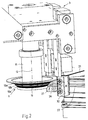
- the plastering device 3 consists of a machine set on (not shown) movable arm, which at its lower, the frame 2 end facing stops 31, 32, a hold-down 35, and configured as a contour cutter 10 tool 1 carries.
- the drive shaft 11 is, for example via a Belt drive rotated by a drive motor.
- the plastic profiles 21, 22 are angled, in particular at right angles welded. These were first mitred cut and welded to the weld 23. Due to the Joining process in the production of the frame 2 creates a outwardly bulging welding bead 24 along the Weld 23, which should be removed as optically neutral as possible. In particular for the outer corner region 27, the inventive Plaster provided, although this on it is not limited in its application.
- the plastering device is in two perpendicular to each other oriented directions 33, 34 movable.
- pneumatic working cylinders are preferably provided, if necessary, at the same time as a damper at Approaching the stops / hold-downs to serve the frame can.
- the drive can also be different, for example by Electric motors and the like can be realized.
- the plasterer carries at its lower end two angled mutually arranged stops 31, 32.
- the angular arrangement the stops 31, 32 corresponds to the angle as the plastic profiles 21, 22 are welded in the frame 2.
- the arrangement of the contour cutter 10 with respect to the Hold-down 35 and the two stops 31, 32 chosen so that when the hold-down 35 and the stops 31, 32 on the Frame or interact with the plastic profiles, So abut on these, the contour cutter 10 exactly the protruding weld bead 24 executes.
- this position is naturally adjustable accordingly to achieve the desired work result.
- the hold-down 35 acts as further stop in the direction of movement of the movement component 33rd
- the at an angle, usually half the connection angle the two plastic profiles runs corresponds to the outer Contour or surface profile 26 of the profiles 21, 22 in the weld area not the contour of the profile cross-section.
- the design of the contour cutter 10 is however created that they the surface profile 26 of the plastic profile 21, 22nd in the weld area 23 corresponds. This will be an optimal one Abtrag the above the weld 23 projecting weld bead 24, without further damaging the surface.
- the contour of the contour cutter 10, the surface course 26 of the plastic profile 21, 22 the weld seam area is equivalent to an arrangement of cutting edges on the circumference a basic body forming the contour cutter 10 is formed.
- the Base body has according to the surface profile 26 of the Plastic profiles 21, 22 at its circumference gradations 10a and / or projections 10b, so that the body about his Length is different thickness.
- At least every section of the Basic body is assigned a cutting edge, with the cutting edge can have a straight or curved edge.
- a straight edge of the cutting edge generated in the outer corner region 27 of the Kunststoffprofiles 21, 22 also a straight edge and a curved cutting a curved edge.
- each disc carries at least one Cutting edge, which processes the plastic profile 21, 22.
- the cutting edges are the cutting edges over the entire circumference of the Basic body or the discs arranged so that a continuous Removal of the weld bead 24 is guaranteed.
- a drive motor is provided for the contour cutter 10.
- the drive motor leaves the contour cutter 10 around in this example vertically extending, or at right angles to the frame plane Rotate standing rotation axis 12.
Landscapes
- Engineering & Computer Science (AREA)
- Mechanical Engineering (AREA)
- Physics & Mathematics (AREA)
- Thermal Sciences (AREA)
- Milling Processes (AREA)
- Processing And Handling Of Plastics And Other Materials For Molding In General (AREA)
- Joining Of Corner Units Of Frames Or Wings (AREA)
- Perforating, Stamping-Out Or Severing By Means Other Than Cutting (AREA)
- Electrical Discharge Machining, Electrochemical Machining, And Combined Machining (AREA)
- Control And Other Processes For Unpacking Of Materials (AREA)
- Confectionery (AREA)
- Undergarments, Swaddling Clothes, Handkerchiefs Or Underwear Materials (AREA)
Priority Applications (1)
| Application Number | Priority Date | Filing Date | Title |
|---|---|---|---|
| PL04028701T PL1537970T3 (pl) | 2003-12-04 | 2004-12-03 | Urządzenie do obróbki |
Applications Claiming Priority (2)
| Application Number | Priority Date | Filing Date | Title |
|---|---|---|---|
| DE20318942U | 2003-12-04 | ||
| DE20318942U DE20318942U1 (de) | 2003-12-04 | 2003-12-04 | Verputzvorrichtung |
Publications (3)
| Publication Number | Publication Date |
|---|---|
| EP1537970A2 true EP1537970A2 (fr) | 2005-06-08 |
| EP1537970A3 EP1537970A3 (fr) | 2006-11-15 |
| EP1537970B1 EP1537970B1 (fr) | 2010-04-14 |
Family
ID=34442560
Family Applications (1)
| Application Number | Title | Priority Date | Filing Date |
|---|---|---|---|
| EP04028701A Active EP1537970B1 (fr) | 2003-12-04 | 2004-12-03 | Dispositif d'ébarbage |
Country Status (6)
| Country | Link |
|---|---|
| US (1) | US20050141974A1 (fr) |
| EP (1) | EP1537970B1 (fr) |
| AT (1) | ATE464168T1 (fr) |
| CA (1) | CA2488998A1 (fr) |
| DE (2) | DE20318942U1 (fr) |
| PL (1) | PL1537970T3 (fr) |
Cited By (2)
| Publication number | Priority date | Publication date | Assignee | Title |
|---|---|---|---|---|
| CN103302357A (zh) * | 2013-05-29 | 2013-09-18 | 皮丕军 | 一种三头倒角机及其控制程序 |
| CN111036968A (zh) * | 2019-12-30 | 2020-04-21 | 武昌船舶重工集团有限公司 | 一种焊缝清根加工设备 |
Families Citing this family (6)
| Publication number | Priority date | Publication date | Assignee | Title |
|---|---|---|---|---|
| DE102005062133A1 (de) * | 2005-12-23 | 2007-06-28 | Willi Stürtz Maschinenbau GmbH | Verfahren zum Bearbeiten von Fensterrahmen |
| US7784161B2 (en) * | 2006-03-27 | 2010-08-31 | Rotox Gmbh | Device for machining the corner area of a frame welded together out of profiled pieces |
| ITMO20060146A1 (it) * | 2006-05-10 | 2007-11-11 | Emmegi Spa | Macchina utensile |
| EP2431006A1 (fr) * | 2010-09-16 | 2012-03-21 | 3M Innovative Properties Company | Procédé de fabrication d'une restauration dentaire |
| DE102019123144A1 (de) * | 2019-08-29 | 2021-03-04 | Rotox Besitz- Und Verwaltungsgesellschaft Mbh | Vorrichtung zum Bearbeiten von aus Profilstücken geschweißten Fenster- oder Türrahmen |
| BE1028581B1 (nl) * | 2020-09-04 | 2022-04-04 | Sobinco Fa | Gereedschap voor het bewerken van de vleugel van een raam of deur |
Citations (4)
| Publication number | Priority date | Publication date | Assignee | Title |
|---|---|---|---|---|
| DE7821618U1 (de) | 1978-07-19 | 1979-04-05 | Radermacher, Richard, 5451 Horhausen | Vorrichtung zum glaetten von eckverschweissten rahmen-eckprofilen von kunststoff-tueren und -fenstern |
| EP0350832A1 (fr) | 1988-07-12 | 1990-01-17 | Bernhard Eisenbach | Dispositif pour chanfreiner les coins exterieurs de châssis de fenêtre ou similaires |
| DE4018145A1 (de) | 1990-06-06 | 1991-12-12 | Bernd Eisenbach | Verputzvorrichtung fuer fensterrahmen o. dgl. |
| DE9305046U1 (de) | 1993-04-02 | 1993-09-09 | Lemuth Praezisionsteile Gmbh | Vorrichtung zum Putzen der beim Verschweißen von Kunststoffprofilen entstehenden Schweißwülste |
Family Cites Families (17)
| Publication number | Priority date | Publication date | Assignee | Title |
|---|---|---|---|---|
| US783946A (en) * | 1903-10-01 | 1905-02-28 | Richard K Gregory | Machine for making laths. |
| US1630173A (en) * | 1926-11-06 | 1927-05-24 | Dumont Joseph | Double carving cutter |
| US2751942A (en) * | 1952-04-10 | 1956-06-26 | Porter Cable Machine Co | Cutter arbor shaft for portable power operated tools |
| US3237275A (en) * | 1963-12-12 | 1966-03-01 | Burton E Middleton | Cutting tools |
| US3708129A (en) * | 1971-01-07 | 1973-01-02 | Munson Mill Machinery Co | Cutter machine |
| US3986543A (en) * | 1975-07-21 | 1976-10-19 | Kimball International, Inc. | Rotary cutter knife |
| DE3020739C2 (de) * | 1980-05-31 | 1986-08-14 | Bernhard 6259 Brechen Eisenbach | Vorrichtung zum Entfernen von überstehenden Schweißraupen o.dgl. |
| DE3711487A1 (de) * | 1986-11-12 | 1988-10-13 | Bernhard Eisenbach | Vorrichtung zum verputzen von fenster- oder tuerrahmen |
| DE3727136A1 (de) * | 1987-08-14 | 1989-02-23 | Urban Maschinenbau | Verfahren und vorrichtung zur bearbeitung der eckverbindungen von rahmen aus kunststoffprofilen |
| DE4018290A1 (de) * | 1990-06-07 | 1991-12-12 | Bernd Eisenbach | Vorrichtung zum bearbeiten von fensterrahmen o. dgl. |
| DE9106839U1 (fr) * | 1990-11-28 | 1991-09-26 | Willi Stuertz Maschinenbau Gmbh, 5466 Neustadt, De | |
| CA2119308C (fr) * | 1994-03-17 | 1996-12-24 | Walter Louis Grassi | Machine pour nettoyer les coins soudes |
| DE19724699A1 (de) * | 1997-06-12 | 1998-12-17 | Bernhard Eisenbach | Verputzvorrichtung für Fenster- oder Türrahmen |
| US5996659A (en) * | 1998-01-09 | 1999-12-07 | Burgess; Michael | Matched pair of plywood edge-banding router bits |
| US6164351A (en) * | 2000-01-05 | 2000-12-26 | Triangle Pacific Corporation | Precision-balanced cutter head and method |
| DE20109451U1 (de) * | 2001-04-12 | 2002-08-22 | Urban Gmbh & Co Maschb Kg | Vorrichtung zum Bearbeiten von Kunststoffprofilen für Fensterrahmen o.dgl. |
| US7219706B2 (en) * | 2002-09-06 | 2007-05-22 | Key Knife, Inc. | Apparatus having adjustable saws for wood cutting |
-
2003
- 2003-12-04 DE DE20318942U patent/DE20318942U1/de not_active Expired - Lifetime
-
2004
- 2004-12-02 US US11/001,095 patent/US20050141974A1/en not_active Abandoned
- 2004-12-03 AT AT04028701T patent/ATE464168T1/de not_active IP Right Cessation
- 2004-12-03 EP EP04028701A patent/EP1537970B1/fr active Active
- 2004-12-03 DE DE502004011025T patent/DE502004011025D1/de active Active
- 2004-12-03 PL PL04028701T patent/PL1537970T3/pl unknown
- 2004-12-03 CA CA002488998A patent/CA2488998A1/fr not_active Abandoned
Patent Citations (4)
| Publication number | Priority date | Publication date | Assignee | Title |
|---|---|---|---|---|
| DE7821618U1 (de) | 1978-07-19 | 1979-04-05 | Radermacher, Richard, 5451 Horhausen | Vorrichtung zum glaetten von eckverschweissten rahmen-eckprofilen von kunststoff-tueren und -fenstern |
| EP0350832A1 (fr) | 1988-07-12 | 1990-01-17 | Bernhard Eisenbach | Dispositif pour chanfreiner les coins exterieurs de châssis de fenêtre ou similaires |
| DE4018145A1 (de) | 1990-06-06 | 1991-12-12 | Bernd Eisenbach | Verputzvorrichtung fuer fensterrahmen o. dgl. |
| DE9305046U1 (de) | 1993-04-02 | 1993-09-09 | Lemuth Praezisionsteile Gmbh | Vorrichtung zum Putzen der beim Verschweißen von Kunststoffprofilen entstehenden Schweißwülste |
Cited By (3)
| Publication number | Priority date | Publication date | Assignee | Title |
|---|---|---|---|---|
| CN103302357A (zh) * | 2013-05-29 | 2013-09-18 | 皮丕军 | 一种三头倒角机及其控制程序 |
| CN103302357B (zh) * | 2013-05-29 | 2016-07-06 | 陈晓慧 | 一种三头倒角机的控制方法 |
| CN111036968A (zh) * | 2019-12-30 | 2020-04-21 | 武昌船舶重工集团有限公司 | 一种焊缝清根加工设备 |
Also Published As
| Publication number | Publication date |
|---|---|
| DE20318942U1 (de) | 2005-04-14 |
| DE502004011025D1 (de) | 2010-05-27 |
| US20050141974A1 (en) | 2005-06-30 |
| CA2488998A1 (fr) | 2005-06-04 |
| ATE464168T1 (de) | 2010-04-15 |
| EP1537970A3 (fr) | 2006-11-15 |
| EP1537970B1 (fr) | 2010-04-14 |
| PL1537970T3 (pl) | 2010-08-31 |
Similar Documents
| Publication | Publication Date | Title |
|---|---|---|
| DE102010061321A1 (de) | Verfahren zum Fräsen einer Ausnehmung in einem Werkstück und Werkstück mit einer Ausnehmung | |
| EP1537970B1 (fr) | Dispositif d'ébarbage | |
| DE102016104806A1 (de) | Verfahren zum Verbinden von Profilstücken | |
| EP3674065A1 (fr) | Procédé et dispositif de soudage de barres profilées | |
| EP1543906A1 (fr) | Unité d'usinage pour le traitement des joints d'angle de cadres en profilés soudés | |
| DE202017102951U1 (de) | Verputzvorrichtung | |
| EP0909602B1 (fr) | Dispositif à ébarber pour châssis de fenêtres ou portes | |
| EP1800783A1 (fr) | Table de coupe et procédé de coupe de sections de profilés | |
| DE2415006C3 (de) | Verfahren zur Herstellung von Fensterrahmen mit Glashalteleiste aus Holz und Vorrichtung zur Durchführung des Verfahrens | |
| DE3137819C2 (de) | Vorrichtung zum Abstechen von Schweißgraten | |
| DE3422101C2 (fr) | ||
| DE3813852C2 (fr) | ||
| EP3736113B1 (fr) | Dispositif et procédé de fabrication d'un élément | |
| DE19905414C2 (de) | Vorrichtung zum Schneiden und Einkerben von Profilen | |
| EP1430996B1 (fr) | Unité d'usinage pour enlever des bavures de soudage des joints d'angle de cadres en profilés en matière plastique soudés | |
| EP0978339B1 (fr) | Dispositif de coupe des profilés de fenêtres ou portes | |
| EP1297923B2 (fr) | Unité d'usinage pour enlever des bavures de soudage des joints d'angle de cadres de fenêtre ou porte en profilés en matière plastique soudés | |
| DE4409813A1 (de) | Vorrichtung zum Zuschneiden von stabförmigen Werkstücken, insbesondere von Glassprossen für Fenster oder Türen | |
| DE2722283C2 (de) | Schneidwerkzeug zum Einschneiden einer Nut | |
| DE4107946A1 (de) | Verfahren und vorrichtung zum fraesen von werkstuecken aus holz oder holzaehnlichem material | |
| DE3036630C2 (de) | Vorrichtung zum Abtragen der Schweißwülste an Eckverbindungen | |
| DE2236087C3 (de) | Vorrichtung zum Bearbeiten der Stoßsteilen von aus Profilen stumpfgeschweißten Teile | |
| DE2628681A1 (de) | Verfahren und vorrichtung zur nachbearbeitung der eckverbindungen von fenster- bzw. tuerrahmen | |
| DE3310307A1 (de) | Vorrichtung zum verputzen der schweissraupe an fensterrahmen od. dgl. | |
| DE19856088A1 (de) | Verfahren zum Herstellen von Fensterrahmen |
Legal Events
| Date | Code | Title | Description |
|---|---|---|---|
| PUAI | Public reference made under article 153(3) epc to a published international application that has entered the european phase |
Free format text: ORIGINAL CODE: 0009012 |
|
| AK | Designated contracting states |
Kind code of ref document: A2 Designated state(s): AT BE BG CH CY CZ DE DK EE ES FI FR GB GR HU IE IS IT LI LT LU MC NL PL PT RO SE SI SK TR |
|
| AX | Request for extension of the european patent |
Extension state: AL BA HR LV MK YU |
|
| PUAL | Search report despatched |
Free format text: ORIGINAL CODE: 0009013 |
|
| AK | Designated contracting states |
Kind code of ref document: A3 Designated state(s): AT BE BG CH CY CZ DE DK EE ES FI FR GB GR HU IE IS IT LI LT LU MC NL PL PT RO SE SI SK TR |
|
| AX | Request for extension of the european patent |
Extension state: AL BA HR LV MK YU |
|
| 17P | Request for examination filed |
Effective date: 20070505 |
|
| 17Q | First examination report despatched |
Effective date: 20070606 |
|
| AKX | Designation fees paid |
Designated state(s): AT BE BG CH CY CZ DE DK EE ES FI FR GB GR HU IE IS IT LI LT LU MC NL PL PT RO SE SI SK TR |
|
| GRAP | Despatch of communication of intention to grant a patent |
Free format text: ORIGINAL CODE: EPIDOSNIGR1 |
|
| GRAS | Grant fee paid |
Free format text: ORIGINAL CODE: EPIDOSNIGR3 |
|
| GRAA | (expected) grant |
Free format text: ORIGINAL CODE: 0009210 |
|
| AK | Designated contracting states |
Kind code of ref document: B1 Designated state(s): AT BE BG CH CY CZ DE DK EE ES FI FR GB GR HU IE IS IT LI LT LU MC NL PL PT RO SE SI SK TR |
|
| REG | Reference to a national code |
Ref country code: GB Ref legal event code: FG4D Free format text: NOT ENGLISH |
|
| REG | Reference to a national code |
Ref country code: CH Ref legal event code: EP |
|
| REG | Reference to a national code |
Ref country code: IE Ref legal event code: FG4D Free format text: LANGUAGE OF EP DOCUMENT: GERMAN |
|
| REF | Corresponds to: |
Ref document number: 502004011025 Country of ref document: DE Date of ref document: 20100527 Kind code of ref document: P |
|
| REG | Reference to a national code |
Ref country code: NL Ref legal event code: VDEP Effective date: 20100414 |
|
| REG | Reference to a national code |
Ref country code: PL Ref legal event code: T3 |
|
| LTIE | Lt: invalidation of european patent or patent extension |
Effective date: 20100414 |
|
| PG25 | Lapsed in a contracting state [announced via postgrant information from national office to epo] |
Ref country code: LT Free format text: LAPSE BECAUSE OF FAILURE TO SUBMIT A TRANSLATION OF THE DESCRIPTION OR TO PAY THE FEE WITHIN THE PRESCRIBED TIME-LIMIT Effective date: 20100414 Ref country code: SE Free format text: LAPSE BECAUSE OF FAILURE TO SUBMIT A TRANSLATION OF THE DESCRIPTION OR TO PAY THE FEE WITHIN THE PRESCRIBED TIME-LIMIT Effective date: 20100414 Ref country code: NL Free format text: LAPSE BECAUSE OF FAILURE TO SUBMIT A TRANSLATION OF THE DESCRIPTION OR TO PAY THE FEE WITHIN THE PRESCRIBED TIME-LIMIT Effective date: 20100414 Ref country code: ES Free format text: LAPSE BECAUSE OF FAILURE TO SUBMIT A TRANSLATION OF THE DESCRIPTION OR TO PAY THE FEE WITHIN THE PRESCRIBED TIME-LIMIT Effective date: 20100725 |
|
| REG | Reference to a national code |
Ref country code: IE Ref legal event code: FD4D |
|
| PG25 | Lapsed in a contracting state [announced via postgrant information from national office to epo] |
Ref country code: IS Free format text: LAPSE BECAUSE OF FAILURE TO SUBMIT A TRANSLATION OF THE DESCRIPTION OR TO PAY THE FEE WITHIN THE PRESCRIBED TIME-LIMIT Effective date: 20100814 Ref country code: FI Free format text: LAPSE BECAUSE OF FAILURE TO SUBMIT A TRANSLATION OF THE DESCRIPTION OR TO PAY THE FEE WITHIN THE PRESCRIBED TIME-LIMIT Effective date: 20100414 Ref country code: SI Free format text: LAPSE BECAUSE OF FAILURE TO SUBMIT A TRANSLATION OF THE DESCRIPTION OR TO PAY THE FEE WITHIN THE PRESCRIBED TIME-LIMIT Effective date: 20100414 |
|
| PG25 | Lapsed in a contracting state [announced via postgrant information from national office to epo] |
Ref country code: CY Free format text: LAPSE BECAUSE OF FAILURE TO SUBMIT A TRANSLATION OF THE DESCRIPTION OR TO PAY THE FEE WITHIN THE PRESCRIBED TIME-LIMIT Effective date: 20100421 Ref country code: GR Free format text: LAPSE BECAUSE OF FAILURE TO SUBMIT A TRANSLATION OF THE DESCRIPTION OR TO PAY THE FEE WITHIN THE PRESCRIBED TIME-LIMIT Effective date: 20100715 |
|
| PG25 | Lapsed in a contracting state [announced via postgrant information from national office to epo] |
Ref country code: PT Free format text: LAPSE BECAUSE OF FAILURE TO SUBMIT A TRANSLATION OF THE DESCRIPTION OR TO PAY THE FEE WITHIN THE PRESCRIBED TIME-LIMIT Effective date: 20100816 Ref country code: DK Free format text: LAPSE BECAUSE OF FAILURE TO SUBMIT A TRANSLATION OF THE DESCRIPTION OR TO PAY THE FEE WITHIN THE PRESCRIBED TIME-LIMIT Effective date: 20100414 Ref country code: IE Free format text: LAPSE BECAUSE OF FAILURE TO SUBMIT A TRANSLATION OF THE DESCRIPTION OR TO PAY THE FEE WITHIN THE PRESCRIBED TIME-LIMIT Effective date: 20100414 Ref country code: EE Free format text: LAPSE BECAUSE OF FAILURE TO SUBMIT A TRANSLATION OF THE DESCRIPTION OR TO PAY THE FEE WITHIN THE PRESCRIBED TIME-LIMIT Effective date: 20100414 |
|
| PLBE | No opposition filed within time limit |
Free format text: ORIGINAL CODE: 0009261 |
|
| STAA | Information on the status of an ep patent application or granted ep patent |
Free format text: STATUS: NO OPPOSITION FILED WITHIN TIME LIMIT |
|
| PG25 | Lapsed in a contracting state [announced via postgrant information from national office to epo] |
Ref country code: SK Free format text: LAPSE BECAUSE OF FAILURE TO SUBMIT A TRANSLATION OF THE DESCRIPTION OR TO PAY THE FEE WITHIN THE PRESCRIBED TIME-LIMIT Effective date: 20100414 Ref country code: RO Free format text: LAPSE BECAUSE OF FAILURE TO SUBMIT A TRANSLATION OF THE DESCRIPTION OR TO PAY THE FEE WITHIN THE PRESCRIBED TIME-LIMIT Effective date: 20100414 |
|
| 26N | No opposition filed |
Effective date: 20110117 |
|
| PG25 | Lapsed in a contracting state [announced via postgrant information from national office to epo] |
Ref country code: MC Free format text: LAPSE BECAUSE OF NON-PAYMENT OF DUE FEES Effective date: 20101231 |
|
| REG | Reference to a national code |
Ref country code: CH Ref legal event code: PL |
|
| PG25 | Lapsed in a contracting state [announced via postgrant information from national office to epo] |
Ref country code: LI Free format text: LAPSE BECAUSE OF NON-PAYMENT OF DUE FEES Effective date: 20101231 Ref country code: CH Free format text: LAPSE BECAUSE OF NON-PAYMENT OF DUE FEES Effective date: 20101231 |
|
| PG25 | Lapsed in a contracting state [announced via postgrant information from national office to epo] |
Ref country code: AT Free format text: LAPSE BECAUSE OF NON-PAYMENT OF DUE FEES Effective date: 20101203 |
|
| REG | Reference to a national code |
Ref country code: AT Ref legal event code: MM01 Ref document number: 464168 Country of ref document: AT Kind code of ref document: T Effective date: 20101203 |
|
| PG25 | Lapsed in a contracting state [announced via postgrant information from national office to epo] |
Ref country code: BG Free format text: LAPSE BECAUSE OF FAILURE TO SUBMIT A TRANSLATION OF THE DESCRIPTION OR TO PAY THE FEE WITHIN THE PRESCRIBED TIME-LIMIT Effective date: 20100414 Ref country code: HU Free format text: LAPSE BECAUSE OF FAILURE TO SUBMIT A TRANSLATION OF THE DESCRIPTION OR TO PAY THE FEE WITHIN THE PRESCRIBED TIME-LIMIT Effective date: 20101015 Ref country code: LU Free format text: LAPSE BECAUSE OF NON-PAYMENT OF DUE FEES Effective date: 20101203 |
|
| PGFP | Annual fee paid to national office [announced via postgrant information from national office to epo] |
Ref country code: CZ Payment date: 20121126 Year of fee payment: 9 |
|
| PGFP | Annual fee paid to national office [announced via postgrant information from national office to epo] |
Ref country code: IT Payment date: 20121222 Year of fee payment: 9 Ref country code: PL Payment date: 20121019 Year of fee payment: 9 Ref country code: TR Payment date: 20121203 Year of fee payment: 9 Ref country code: GB Payment date: 20121218 Year of fee payment: 9 |
|
| PGFP | Annual fee paid to national office [announced via postgrant information from national office to epo] |
Ref country code: BE Payment date: 20121217 Year of fee payment: 9 Ref country code: FR Payment date: 20130123 Year of fee payment: 9 |
|
| PG25 | Lapsed in a contracting state [announced via postgrant information from national office to epo] |
Ref country code: BG Free format text: LAPSE BECAUSE OF FAILURE TO SUBMIT A TRANSLATION OF THE DESCRIPTION OR TO PAY THE FEE WITHIN THE PRESCRIBED TIME-LIMIT Effective date: 20100714 |
|
| BERE | Be: lapsed |
Owner name: URBAN G.M.B.H. & CO. MASCHINENBAU KG Effective date: 20131231 |
|
| GBPC | Gb: european patent ceased through non-payment of renewal fee |
Effective date: 20131203 |
|
| PG25 | Lapsed in a contracting state [announced via postgrant information from national office to epo] |
Ref country code: CZ Free format text: LAPSE BECAUSE OF NON-PAYMENT OF DUE FEES Effective date: 20131203 |
|
| REG | Reference to a national code |
Ref country code: FR Ref legal event code: ST Effective date: 20140829 |
|
| PG25 | Lapsed in a contracting state [announced via postgrant information from national office to epo] |
Ref country code: BE Free format text: LAPSE BECAUSE OF NON-PAYMENT OF DUE FEES Effective date: 20131231 |
|
| PG25 | Lapsed in a contracting state [announced via postgrant information from national office to epo] |
Ref country code: FR Free format text: LAPSE BECAUSE OF NON-PAYMENT OF DUE FEES Effective date: 20131231 Ref country code: GB Free format text: LAPSE BECAUSE OF NON-PAYMENT OF DUE FEES Effective date: 20131203 |
|
| PG25 | Lapsed in a contracting state [announced via postgrant information from national office to epo] |
Ref country code: PL Free format text: LAPSE BECAUSE OF NON-PAYMENT OF DUE FEES Effective date: 20131203 |
|
| REG | Reference to a national code |
Ref country code: PL Ref legal event code: LAPE |
|
| PG25 | Lapsed in a contracting state [announced via postgrant information from national office to epo] |
Ref country code: IT Free format text: LAPSE BECAUSE OF NON-PAYMENT OF DUE FEES Effective date: 20131231 |
|
| PG25 | Lapsed in a contracting state [announced via postgrant information from national office to epo] |
Ref country code: TR Free format text: LAPSE BECAUSE OF NON-PAYMENT OF DUE FEES Effective date: 20131203 |
|
| PG25 | Lapsed in a contracting state [announced via postgrant information from national office to epo] |
Ref country code: IT Free format text: LAPSE BECAUSE OF NON-PAYMENT OF DUE FEES Effective date: 20131203 |
|
| REG | Reference to a national code |
Ref country code: DE Ref legal event code: R082 Ref document number: 502004011025 Country of ref document: DE Representative=s name: PATENTANWAELTE OLBRICHT, BUCHHOLD, KEULERTZ PA, DE |
|
| REG | Reference to a national code |
Ref country code: DE Ref legal event code: R082 Ref document number: 502004011025 Country of ref document: DE Representative=s name: PATENTANWAELTE OLBRICHT, BUCHHOLD, KEULERTZ PA, DE |
|
| PGFP | Annual fee paid to national office [announced via postgrant information from national office to epo] |
Ref country code: DE Payment date: 20231231 Year of fee payment: 20 |