EP1537970A2 - Deburring device - Google Patents
Deburring device Download PDFInfo
- Publication number
- EP1537970A2 EP1537970A2 EP04028701A EP04028701A EP1537970A2 EP 1537970 A2 EP1537970 A2 EP 1537970A2 EP 04028701 A EP04028701 A EP 04028701A EP 04028701 A EP04028701 A EP 04028701A EP 1537970 A2 EP1537970 A2 EP 1537970A2
- Authority
- EP
- European Patent Office
- Prior art keywords
- frame
- plastering device
- contour
- plastering
- cutter
- Prior art date
- Legal status (The legal status is an assumption and is not a legal conclusion. Google has not performed a legal analysis and makes no representation as to the accuracy of the status listed.)
- Granted
Links
- 238000003801 milling Methods 0.000 claims abstract description 12
- 239000011324 bead Substances 0.000 claims description 26
- 238000005520 cutting process Methods 0.000 claims description 24
- 238000003754 machining Methods 0.000 claims description 13
- 238000003466 welding Methods 0.000 claims description 12
- 238000012545 processing Methods 0.000 claims description 11
- 239000000463 material Substances 0.000 abstract 2
- 238000000034 method Methods 0.000 description 9
- 239000011505 plaster Substances 0.000 description 6
- 238000013461 design Methods 0.000 description 5
- 230000002349 favourable effect Effects 0.000 description 3
- 239000000523 sample Substances 0.000 description 3
- 230000001419 dependent effect Effects 0.000 description 2
- 238000004519 manufacturing process Methods 0.000 description 2
- 238000005070 sampling Methods 0.000 description 2
- 238000002679 ablation Methods 0.000 description 1
- 238000013459 approach Methods 0.000 description 1
- 239000002131 composite material Substances 0.000 description 1
- 230000008094 contradictory effect Effects 0.000 description 1
- 238000011161 development Methods 0.000 description 1
- 230000000694 effects Effects 0.000 description 1
- 238000009472 formulation Methods 0.000 description 1
- 230000001771 impaired effect Effects 0.000 description 1
- 238000005304 joining Methods 0.000 description 1
- 239000002184 metal Substances 0.000 description 1
- 239000000203 mixture Substances 0.000 description 1
- 230000007935 neutral effect Effects 0.000 description 1
- 230000003287 optical effect Effects 0.000 description 1
- 238000003825 pressing Methods 0.000 description 1
- 238000010926 purge Methods 0.000 description 1
- 230000000284 resting effect Effects 0.000 description 1
- 238000004826 seaming Methods 0.000 description 1
- 238000012549 training Methods 0.000 description 1
Images


Classifications
-
- B—PERFORMING OPERATIONS; TRANSPORTING
- B23—MACHINE TOOLS; METAL-WORKING NOT OTHERWISE PROVIDED FOR
- B23C—MILLING
- B23C3/00—Milling particular work; Special milling operations; Machines therefor
- B23C3/12—Trimming or finishing edges, e.g. deburring welded corners
- B23C3/128—Trimming or finishing edges of doors and windows
-
- B—PERFORMING OPERATIONS; TRANSPORTING
- B29—WORKING OF PLASTICS; WORKING OF SUBSTANCES IN A PLASTIC STATE IN GENERAL
- B29C—SHAPING OR JOINING OF PLASTICS; SHAPING OF MATERIAL IN A PLASTIC STATE, NOT OTHERWISE PROVIDED FOR; AFTER-TREATMENT OF THE SHAPED PRODUCTS, e.g. REPAIRING
- B29C37/00—Component parts, details, accessories or auxiliary operations, not covered by group B29C33/00 or B29C35/00
- B29C37/02—Deburring or deflashing
- B29C37/04—Deburring or deflashing of welded articles, e.g. deburring or deflashing in combination with welding
-
- B—PERFORMING OPERATIONS; TRANSPORTING
- B29—WORKING OF PLASTICS; WORKING OF SUBSTANCES IN A PLASTIC STATE IN GENERAL
- B29L—INDEXING SCHEME ASSOCIATED WITH SUBCLASS B29C, RELATING TO PARTICULAR ARTICLES
- B29L2031/00—Other particular articles
- B29L2031/001—Profiled members, e.g. beams, sections
- B29L2031/003—Profiled members, e.g. beams, sections having a profiled transverse cross-section
- B29L2031/005—Profiled members, e.g. beams, sections having a profiled transverse cross-section for making window frames
-
- Y—GENERAL TAGGING OF NEW TECHNOLOGICAL DEVELOPMENTS; GENERAL TAGGING OF CROSS-SECTIONAL TECHNOLOGIES SPANNING OVER SEVERAL SECTIONS OF THE IPC; TECHNICAL SUBJECTS COVERED BY FORMER USPC CROSS-REFERENCE ART COLLECTIONS [XRACs] AND DIGESTS
- Y10—TECHNICAL SUBJECTS COVERED BY FORMER USPC
- Y10T—TECHNICAL SUBJECTS COVERED BY FORMER US CLASSIFICATION
- Y10T409/00—Gear cutting, milling, or planing
- Y10T409/30—Milling
- Y10T409/304144—Means to trim edge
-
- Y—GENERAL TAGGING OF NEW TECHNOLOGICAL DEVELOPMENTS; GENERAL TAGGING OF CROSS-SECTIONAL TECHNOLOGIES SPANNING OVER SEVERAL SECTIONS OF THE IPC; TECHNICAL SUBJECTS COVERED BY FORMER USPC CROSS-REFERENCE ART COLLECTIONS [XRACs] AND DIGESTS
- Y10—TECHNICAL SUBJECTS COVERED BY FORMER USPC
- Y10T—TECHNICAL SUBJECTS COVERED BY FORMER US CLASSIFICATION
- Y10T409/00—Gear cutting, milling, or planing
- Y10T409/30—Milling
- Y10T409/3042—Means to remove scale or raised surface imperfection
-
- Y—GENERAL TAGGING OF NEW TECHNOLOGICAL DEVELOPMENTS; GENERAL TAGGING OF CROSS-SECTIONAL TECHNOLOGIES SPANNING OVER SEVERAL SECTIONS OF THE IPC; TECHNICAL SUBJECTS COVERED BY FORMER USPC CROSS-REFERENCE ART COLLECTIONS [XRACs] AND DIGESTS
- Y10—TECHNICAL SUBJECTS COVERED BY FORMER USPC
- Y10T—TECHNICAL SUBJECTS COVERED BY FORMER US CLASSIFICATION
- Y10T409/00—Gear cutting, milling, or planing
- Y10T409/30—Milling
- Y10T409/306664—Milling including means to infeed rotary cutter toward work
- Y10T409/306776—Axially
- Y10T409/307168—Plural cutters
Definitions
- the invention relates to a plastering device for welded together Plastic profiles existing frame or Frame parts, for windows, doors or the like, wherein the Plaster a rotating, metal cutting tool which, for the removal of the at the weld of the Plastic profiles protruding weld bead is used.
- Plastering devices described in the introduction are used the at the weld as a result of a butt welding resulting, outwardly projecting bead to remove.
- mitring is used cut plastic profiles for example to a Window or door frame or the like welded. Because the Plastic profiles are mitred, also runs the plane of the weld under a corresponding miter angle. Be plastic profiles for example in a right Angle welded together, the miter is 45 ° to the neighboring, welded together frame parts.
- the European patent specification 350 832 known is an outside corner plastering device for window frames or the like.
- a metal-cutting Tool is used here a circular saw blade.
- a sensing device is provided which with a Control is connected.
- the probe has one with the circular saw blade and relative to this, to axially movable Button on, which touches the frame.
- the push buttons cause a deflection in the frame level and perpendicular thereto in a radial or axial Movement of the circular saw blade switched.
- buttons the contour scanned and a circular saw blade due to the position of the Button controlled.
- buttons are in connection with a Arrangement that possesses a considerable mass. In case of an unintentional Approaching the entire arrangement, the Under certain circumstances, buttons can easily be damaged. Furthermore is to note that the sampling has to be done permanently, ie even during chip-removing machining and flying around If necessary, swarf into the gap between probe and profile and possibly falsify the sampling result, which, of course, may also be editing fails.
- the invention has set itself the task of a plastering device as described above, to improve to that effect, that the processing result when processing the weld bead is improved.
- the invention is based on a Plastering device as described in the beginning and proposes in that a contour milling cutter is provided as a tool whose contour the surface profile of the plastic profile in the weld area equivalent.
- the invention proposes that instead of a circular saw blade a contour cutter is used.
- the contour cutter is the same designed that the contour of the surface of the Plastic profiles in the weld area corresponds and thus optimally adapted. This takes into account that in Welding area the plastic profiles dull, mitred welded together and the surface course in the Weld area not necessarily the cross section of the plastic profile equivalent.
- the tool is exactly the adapted surface course, thereby automatically a very high optical quality of the weld seaming arises, the with the circular saw blades due to the finite Width of the circular saw blades can not be achieved.
- the two plastic profiles to be welded together already create a level between themselves, the following Frame level.
- the level veaji at least by two welded together plastic profiles respectively Frame parts or frame is defined.
- frame also Frame parts, for example, made of only two plastic profiles welded, for example, because these elements are then behind in conjunction with other frame parts or frame to connect are.
- frame is therefore under the framework also Parts of the frame, at least consisting of two together welded plastic profiles understood.
- the invention is preferred for removing the weld bead on the outside corner of two angularly welded plastic profiles used. But this is not the invention.
- the invention is also at two blunt, not angled welded plastic profiles on both sides the plastic profile used.
- the visible Frame area of the rollover is in the miter area optimally processed the invention.
- the contour of the contour cutter corresponds to the desired surface course the plastic profile.
- the contour can be one follow the continuous line.
- the invention is provided that the contour cutter along has its gradations of rotation axis. These gradations can each be formed in equal stages. According to a variant of the invention, the gradations are different chosen big. This provides the opportunity to Contour milling cutter the different surface course of the Adapt plastic profiles. Increase projections on the contour milling cutter the shape design. Create projections on the cutter For example, depressions or incisions on the profile.
- a continuous course can be a straight or curved one Track follow, with the straight line relative to the axis of rotation is arranged parallel or at an angle.
- the curved one Track can be a circle, a curve or a curved one Follow the line.
- Other than here listed courses are not excluded for the surface of the contour cutter.
- the surface of Contour cutter For processing the plastic profile is the surface of Contour cutter provided with cutting edges. At least two cutting edges circulate on flight circles with different Diameter the axis of rotation of the contour cutter. These two Cutting is according to an embodiment of the invention to two Disks of different diameters arranged. Of the Contour milling cutter is according to a further embodiment of the invention from a variety of slices, each at least wear a cutting edge. The edges themselves are partly straight or curved. Together they form the surface contour of the router with its gradations, tabs or curved lines. An advantage of such a contour cutter lies in the fact that the individual discs may differ can be assembled. It is also possible if the cutting edge is worn, the corresponding disc easy to replace. This shortens downtime during production the machine.
- the contour cutter is not made of individual Put together slices, but from a one-piece, rotational, provided with gradations or projections Form body.
- the cutting edges are on arranged around its circumference. At least every level is at least assigned a cutting edge.
- the projections are also through Cutting formed, the width of which may be narrower is, than that of the rest of the cutting.
- Verputzvorraum two angled, preferred has right-angled stops and the plastic profiles the frame ever abut a stop.
- the frame rests on a working table and the machining table two angled, preferably at right angles has arranged stops and the plastic profiles of the Frame abut each stop.
- the Verputzvorraum with respect to the location of the table Stops exactly set and on the arrangement of additional Attacks on the plastering can at this Variant be waived.
- the invention proposes that the plastering device a hold-down, which is substantially rectangular acts at the frame level. Especially in combination with the two angularly arranged attacks is achieved by that the plastering device with respect to the three spatial coordinates in relation to the weld seam area to be worked is exactly positioned. In this case, preferably the act both attacks at the frame level or in one plane the this is parallel, the hold-down acts like a stop at right angles. Optionally, the hold-down also serves for exact pressing of the frame on a surface.
- a hold-down is provided which is substantially perpendicular to the frame level.
- the invention offers in principle two alternatives.
- the Arrangement of the stops or the hold-down are in the first variant of the plastering device and in the another variant arranged on the processing table. At long last But it depends on the exact alignment of the attacks and of the hold-down with respect to the contour milling cutter for a fully satisfactory Work result.
- the advantage of the arrangement of Stops and the hold on the plastering is especially in that it depends on the exact tension of the frame on the working table does not arrive, since the plastering device through the three points, the two attacks and the Hold down, the respective processing position for ablation the welding bead itself searches, finds and processes exactly. If necessary, but in the attacks are appropriate Sensors for the exact concern of the frame to the Attacks provided, even with the other variant one highest machining quality to achieve.
- the axis of rotation of the contour cutter perpendicular to the Frame level is oriented. Such a design allows it to arrange the rotary drive above the frame where this does not bother. It is of course possible, the axis of rotation of the contour cutter also at an angle or parallel to the Orient the frame plane, the contour cutter is then accordingly trained differently.
- the plastering device For an exact positioning of the plastering device is provided that these are both at right angles to the frame plane as well is movable parallel to the frame plane. Especially if the Plaster equipped with stops and hold-down is, it depends on the exact position of the processed Do not weld, because the plastering due to the guide through the stops and the hold down the exactly meets the respective machining position. A mobility with respect to the frame plane and at right angles to it is here One way another way is to do the Plastering device along other oriented axes in space to move. This too is part of the invention.
- plastering device in the direction the axis of rotation is movable, this being in a Variant of the invention also at the same time perpendicular to Frame level is.
- the position of the contour cutter with respect to the attacks or the hold-down while adjustable, in use the plastering device is set but. Due to the adjustability concerning the attacks or the hold-down the contour cutter is in its machining position with regard to the edges of the profile or their top surfaces, So those surfaces or edges, the cooperate with the stop or hold-down, aligned to achieve an optimal machining result.
- the contour cutter is movable relative to the hold-down.
- the hold-down is used in particular, the frame especially before the actual to fix machining.
- the contour cutter is then perpendicular to the frame plane, the effective direction of the blank holder, movable and then has a corresponding stop on to work off the weld bead exactly fitting. thats why it favorable that the contour cutter on the plastering is movable, in particular positionable arranged.
- the contour cutter So is relative to the plastering in one variant according to the invention movable or in another Variant determined in this regard and learns its positioning and movement solely by the movement of the plasterer throughout.
- the invention therefore shows several variants, such as the invention Plaster used with the contour cutter can be.
- a significant advantage is that according to the invention First, the frame comes to rest on the attacks, the Downholder fixed the frame and afterwards the contour cutter wears off the weld bead. Since the stop or the Hold-down is formed over a large area, they do not work as a button to scan the exact contour, but put the Position of Verputzvoriques with respect to the processed Welding bead stuck. This is cleverly done this definition before the actual machining, causing the danger that a pinched chip will cause the exact positioning of the frame and thus also the exact processing impaired, greatly minimized.
- an air purge for example, by appropriate air nozzles be provided to further reduce this risk.
- the object of the invention is also a Kunststoffrahmenverputzmaschine solved that for removing protruding Welding beads are provided, which are attached to the Forming a weld of welded plastic profiles, wherein the Kunststoffrahmenverputzmaschine a plastering device used as described.
- the plastering device is part of a more complex plastic frame plastering machine, how to process or rework the Welding beads after welding the plastic profiles too a frame is used.
- the invention is therefore not only can be realized in a single device, but achieved in particular in combination with other elements advantages, as the simple Design is susceptible to interference and therefore a reliable Machine leads and another because of the fast Processing leads to higher performance.
- the plastering device 3 consists of a machine set on (not shown) movable arm, which at its lower, the frame 2 end facing stops 31, 32, a hold-down 35, and configured as a contour cutter 10 tool 1 carries.
- the drive shaft 11 is, for example via a Belt drive rotated by a drive motor.
- the plastic profiles 21, 22 are angled, in particular at right angles welded. These were first mitred cut and welded to the weld 23. Due to the Joining process in the production of the frame 2 creates a outwardly bulging welding bead 24 along the Weld 23, which should be removed as optically neutral as possible. In particular for the outer corner region 27, the inventive Plaster provided, although this on it is not limited in its application.
- the plastering device is in two perpendicular to each other oriented directions 33, 34 movable.
- pneumatic working cylinders are preferably provided, if necessary, at the same time as a damper at Approaching the stops / hold-downs to serve the frame can.
- the drive can also be different, for example by Electric motors and the like can be realized.
- the plasterer carries at its lower end two angled mutually arranged stops 31, 32.
- the angular arrangement the stops 31, 32 corresponds to the angle as the plastic profiles 21, 22 are welded in the frame 2.
- the arrangement of the contour cutter 10 with respect to the Hold-down 35 and the two stops 31, 32 chosen so that when the hold-down 35 and the stops 31, 32 on the Frame or interact with the plastic profiles, So abut on these, the contour cutter 10 exactly the protruding weld bead 24 executes.
- this position is naturally adjustable accordingly to achieve the desired work result.
- the hold-down 35 acts as further stop in the direction of movement of the movement component 33rd
- the at an angle, usually half the connection angle the two plastic profiles runs corresponds to the outer Contour or surface profile 26 of the profiles 21, 22 in the weld area not the contour of the profile cross-section.
- the design of the contour cutter 10 is however created that they the surface profile 26 of the plastic profile 21, 22nd in the weld area 23 corresponds. This will be an optimal one Abtrag the above the weld 23 projecting weld bead 24, without further damaging the surface.
- the contour of the contour cutter 10, the surface course 26 of the plastic profile 21, 22 the weld seam area is equivalent to an arrangement of cutting edges on the circumference a basic body forming the contour cutter 10 is formed.
- the Base body has according to the surface profile 26 of the Plastic profiles 21, 22 at its circumference gradations 10a and / or projections 10b, so that the body about his Length is different thickness.
- At least every section of the Basic body is assigned a cutting edge, with the cutting edge can have a straight or curved edge.
- a straight edge of the cutting edge generated in the outer corner region 27 of the Kunststoffprofiles 21, 22 also a straight edge and a curved cutting a curved edge.
- each disc carries at least one Cutting edge, which processes the plastic profile 21, 22.
- the cutting edges are the cutting edges over the entire circumference of the Basic body or the discs arranged so that a continuous Removal of the weld bead 24 is guaranteed.
- a drive motor is provided for the contour cutter 10.
- the drive motor leaves the contour cutter 10 around in this example vertically extending, or at right angles to the frame plane Rotate standing rotation axis 12.
Abstract
Description
Die Erfindung betrifft eine Verputzvorrichtung für aus zusammengeschweißten Kunststoffprofilen bestehende Rahmen oder Rahmenteile, für Fenster, Türen oder dergleichen, wobei die Verputzvorrichtung ein rotierendes, spanabhebendes Werkzeug aufweist, welches zum Abtragen der an der Schweißnaht des Kunststoffprofiles überstehenden Schweißraupe dient.The invention relates to a plastering device for welded together Plastic profiles existing frame or Frame parts, for windows, doors or the like, wherein the Plaster a rotating, metal cutting tool which, for the removal of the at the weld of the Plastic profiles protruding weld bead is used.
Eingangs beschriebene Verputzvorrichtungen werden dafür eingesetzt, die an der Schweißnaht in Folge eines Stumpfschweißvorganges entstandenen, nach außen überstehende Schweißraupe zu entfernen. In einem Stumpfschweißen werden dabei die auf Gehrung geschnittenen Kunststoffprofile zum Beispiel zu einem Fenster- oder Türrahmen oder dergleichen verschweißt. Da die Kunststoffprofile auf Gehrung geschnitten sind, verläuft auch die Ebene der Schweißnaht unter einem entsprechenden Gehrungswinkel. Werden Kunststoffprofile zum Beispiel in einem rechten Winkel miteinander verschweißt, so beträgt die Gehrung 45° zu dem benachtbarten, miteinander verschweißten Rahmenteilen.Plastering devices described in the introduction are used the at the weld as a result of a butt welding resulting, outwardly projecting bead to remove. In butt welding, mitring is used cut plastic profiles for example to a Window or door frame or the like welded. Because the Plastic profiles are mitred, also runs the plane of the weld under a corresponding miter angle. Be plastic profiles for example in a right Angle welded together, the miter is 45 ° to the neighboring, welded together frame parts.
Im Stand der Technik ist zum Beispiel die europäische Patentschrift 350 832 bekannt. Hier ist eine Außeneckverputzvorrichtung für Fensterrahmen oder dergleichen beschrieben. Als spanabhebendes Werkzeug wird hier ein Kreissägeblatt eingesetzt. Des Weiteren ist eine Tastvorrichtung vorgesehen, die mit einer Steuerung verbunden ist. Die Tastvorrichtung weist dazu einen mit dem Kreissägeblatt und relativ zu diesem, dazu axial bewegbaren Taster auf, der den Rahmen antastet. Dazu tastet der Taster die Fensterrahmen an einer Taststelle an, die in der Ebene des Kreissägeblattes liegt und gegenüber der Bearbeitungsstelle seitlich zum Fensterrahmen hin versetzt ist. Hierdurch wird durch die Taster eine Auslenkung in der Rahmenebene und senkrecht hierzu in eine radiale beziehungsweise axiale Bewegung des Kreissägeblattes geschaltet.For example, in the prior art is the European patent specification 350 832 known. Here is an outside corner plastering device for window frames or the like. As a metal-cutting Tool is used here a circular saw blade. Furthermore, a sensing device is provided which with a Control is connected. The probe has one with the circular saw blade and relative to this, to axially movable Button on, which touches the frame. For that scans the Taster the window frames at a tactile point in the Level of the circular saw blade lies and opposite the processing point offset laterally to the window frame. hereby the push buttons cause a deflection in the frame level and perpendicular thereto in a radial or axial Movement of the circular saw blade switched.
Letztendlich wird im Stand der Technik mit Tastern die Kontur abgetastet und ein Kreissägenblatt aufgrund der Stellung der Taster gesteuert.Finally, in the prior art with buttons the contour scanned and a circular saw blade due to the position of the Button controlled.
Eine solche Vorgehensweise ist vielleicht noch bei verhältnismäßig groben Profilkonturen einsetzbar, da natürlich die endliche Breite des Kreissägeblattes sowie auch die endliche Breite der Taster die Genauigkeit der Bearbeitung letztendlich definieren. Filigranere Profile werden allerdings mit dieser Vorgehensweise optisch beschädigt oder der Schweißwulst nicht vollständig entfernt. Dies ist nicht erwünscht.Such an approach may still be proportionate coarse profile contours used, since of course the finite Width of the circular saw blade as well as the finite Width of the buttons the accuracy of the machining ultimately define. However, filigree profiles are with this Procedure visually damaged or the weld bead not completely removed. This is not wanted.
Des Weiteren ist zu beachten, daß die Abtastung nicht tatsächlich an der Schweißraupe erfolgt, sondern seitlich versetzt. Dies führt dazu, daß nicht tatsächlich der Oberflächenbeziehungsweise Konturverlauf im Gehrungsbereich erfaßt wird, sondern ein Konturverlauf der seitlich daneben liegt und gegebenenfalls zum Beispiel der Querschnittsfläche (einem rechtwinkligen Schnitt) entspricht. Hieraus resultieren Maßungenauigkeiten.It should also be noted that the sample is not actually takes place at the weld bead, but laterally offset. This results in not actually the surface relationship Contour profile is detected in the miter area, but a contour of the side lies next to it and, where appropriate for example, the cross-sectional area (a right-angled Section) corresponds. This results in dimensional inaccuracies.
Letztendlich ist auch die Ausgestaltung mit den Tastern widersprüchlich, da für ein möglichst exaktes Ergebnis die Taster sehr klein und filigran ausgebildet sein müssen, um den Konturenverlauf optimal zu folgen, auf der anderen Seite aber zu beachten ist, daß die Taster in Verbindung stehen mit einer Anordnung, die eine erhebliche Masse besitzt. Bei einem unbeabsichtigten Heranfahren der gesamten Anordnung können die Taster unter Umständen leicht Schaden nehmen. Des Weiteren ist zu beachten, daß die Abtastung permanent zu erfolgen hat, also auch während der spanablösenden Bearbeitung und herumfliegende Späne gegebenenfalls in den Spalt zwischen Taster und Profil gelangen können, und so das Abtastergebnis möglicherweise verfälschen, wodurch natürlich auch die Bearbeitung möglicherweise mißlingt.Finally, the design with the buttons is contradictory, because for as exact a result as possible the buttons must be very small and filigree to the contour optimal to follow, but on the other hand too note that the buttons are in connection with a Arrangement that possesses a considerable mass. In case of an unintentional Approaching the entire arrangement, the Under certain circumstances, buttons can easily be damaged. Furthermore is to note that the sampling has to be done permanently, ie even during chip-removing machining and flying around If necessary, swarf into the gap between probe and profile and possibly falsify the sampling result, which, of course, may also be editing fails.
Die Erfindung hat es sich zur Aufgabe gemacht, eine Verputzvorrichtung wie eingangs beschrieben, dahingehend zu verbessern, daß das Bearbeitungsergebnis beim Abarbeiten der Schweißraupe verbessert wird.The invention has set itself the task of a plastering device as described above, to improve to that effect, that the processing result when processing the weld bead is improved.
Zur Lösung dieser Aufgabe geht die Erfindung aus von einer Verputzvorrichtung wie eingangs beschrieben und schlägt vor, daß als Werkzeug ein Konturfräser vorgesehen ist, dessen Kontur dem Oberflächenverlauf des Kunststoffprofiles im Schweißnahtbereich entspricht.To solve this problem, the invention is based on a Plastering device as described in the beginning and proposes in that a contour milling cutter is provided as a tool whose contour the surface profile of the plastic profile in the weld area equivalent.
Die Erfindung schlägt vor, daß anstelle eines Kreissägeblattes ein Konturfräser eingesetzt wird. Dabei ist der Konturfräser so ausgestaltet, daß dessen Kontur dem Oberflächenverlauf des Kunststoffprofiles im Schweißnahtbereich entspricht und somit optimal angepaßt ist. Hierbei wird berücksichtigt, daß im Schweißnahtbereich die Kunststoffprofile stumpf, unter Gehrung miteinander verschweißt sind und der Oberflächenverlauf im Schweißnahtbereich nicht unbedingt dem Querschnitt des Kunststoffprofiles entspricht. Somit wird das Werkzeug exakt dem gewünschten Oberflächenverlauf angepaßt, wodurch automatisch eine sehr hohe, optische Güte der Schweißnahtbearbeitung entsteht, die mit den Kreissägeblättern aufgrund der endlichen Breite der Kreissägeblätter nicht erreichtbar ist.The invention proposes that instead of a circular saw blade a contour cutter is used. The contour cutter is the same designed that the contour of the surface of the Plastic profiles in the weld area corresponds and thus optimally adapted. This takes into account that in Welding area the plastic profiles dull, mitred welded together and the surface course in the Weld area not necessarily the cross section of the plastic profile equivalent. Thus, the tool is exactly the adapted surface course, thereby automatically a very high optical quality of the weld seaming arises, the with the circular saw blades due to the finite Width of the circular saw blades can not be achieved.
Es folgt unmittelbar eine Verbesserung des Ergebnisses beim Einsatz der erfindungsgemäßen Verputzvorrichtung.It immediately follows an improvement in the result Use of the plastering device according to the invention.
Die beiden miteinander zu verschweißenden Kunststoffprofile spannen zwischen sich bereits eine Ebene auf, die hinterher der Rahmenebene entsprechen wird. Im Sinne der Erfindung wird daher als Rahmenebene die Ebene vestanden, die zumindest durch zwei miteinander verschweißten Kunststoffprofilen beziehungsweise Rahmenteile beziehungsweise Rahmen definiert ist.The two plastic profiles to be welded together already create a level between themselves, the following Frame level. For the purposes of the invention is therefore as a frame level, the level vestanden, at least by two welded together plastic profiles respectively Frame parts or frame is defined.
Natürlich versteht die Erfindung unter dem Begriff Rahmen auch Rahmenteile, die zum Beispiel aus nur zwei Kunststoffprofilen verschweißt sind, zum Beispiel weil diese Elemente dann hinterher im Verbund mit anderen Rahmenteilen oder Rahmen zu Verbinden sind. Im Sinne der Erfindung wird daher unter Rahmen auch Teile des Rahmens, zumindest bestehend aus zwei miteinander verschweißten Kunststoffprofilen verstanden. Of course, the invention understands the term frame also Frame parts, for example, made of only two plastic profiles welded, for example, because these elements are then behind in conjunction with other frame parts or frame to connect are. For the purposes of the invention is therefore under the framework also Parts of the frame, at least consisting of two together welded plastic profiles understood.
Die Erfindung wird dabei bevorzugt zum Abtragen der Schweißraupe am Außeneck zweier winklig verschweißter Kunststoffprofile eingesetzt. Hierauf ist die Erfindung aber nicht festgelegt. Die Erfindung ist auch bei zwei stumpf, nicht winklig miteinander verschweißten Kunststoffprofilen auf beiden Seiten des Kunststoffprofiles einsetzbar. Insbesondere der sichtbare Rahmenbereich des Überschlages wird im Gehrungsbereich durch die Erfindung optimal bearbeitet.The invention is preferred for removing the weld bead on the outside corner of two angularly welded plastic profiles used. But this is not the invention. The invention is also at two blunt, not angled welded plastic profiles on both sides the plastic profile used. In particular, the visible Frame area of the rollover is in the miter area optimally processed the invention.
Die Kontur des Konturfräsers entspricht dem gewünschten Oberflächenverlauf des Kunststoffprofiles. Die Kontur kann einer kontinuierlich verlaufenden Linie folgen. Nach einer Ausführung der Erfindung ist jedoch vorgesehen, daß der Konturfräser entlang seiner Rotationsachse Abstufungen aufweist. Diese Abstufungen können jeweils in gleich großen Stufen gebildet sein. Nach einer Variante der Erfindung sind die Abstufungen unterschiedlich groß gewählt. Dies bietet die Möglichkeit, den Konturfräser dem unterschiedlichen Oberflächenverlauf der Kunststoffprofile anzupassen. Vorsprünge am Konturfräser erhöhen die Formgestaltung. Vorsprünge an dem Fräser erzeugen beispielsweise Vertiefungen bzw. Einschnitte an dem Profil.The contour of the contour cutter corresponds to the desired surface course the plastic profile. The contour can be one follow the continuous line. After an execution However, the invention is provided that the contour cutter along has its gradations of rotation axis. These gradations can each be formed in equal stages. According to a variant of the invention, the gradations are different chosen big. This provides the opportunity to Contour milling cutter the different surface course of the Adapt plastic profiles. Increase projections on the contour milling cutter the shape design. Create projections on the cutter For example, depressions or incisions on the profile.
Nicht nur ein kontinuierlicher oder stufenförmiger Verlauf der Oberfläche des Konturfräsers ist möglich, sondern auch die Kombination von kontinuierlichem und stufenförmigem Verlauf. Ein kontinuierlicher Verlauf kann einer geraden oder gekrümmten Bahn folgen, wobei die Gerade gegenüber der Rotationsachse parallel oder in einem Winkel angeordnet ist. Die gekrümmte Bahn kann einem Kreis, einer Kurve oder einer geschwungenen Linie folgen. Auch andere als hier aufgeführte Verläufe sind für die Oberfläche des Konturfräsers nicht ausgeschlossen.Not just a continuous or stepped course of Surface of the router is possible, but also the Combination of continuous and stepped course. A continuous course can be a straight or curved one Track follow, with the straight line relative to the axis of rotation is arranged parallel or at an angle. The curved one Track can be a circle, a curve or a curved one Follow the line. Other than here listed courses are not excluded for the surface of the contour cutter.
Zur Bearbeitung des Kunststoffprofiles ist die Oberfläche des Konturfräsers mit spanabhebenden Schneiden versehen. Zumindest zwei Schneiden umlaufen auf Flugkreisen mit unterschiedlichem Durchmesser die Rotationsachse des Konturfräsers. Diese beiden Schneiden sind nach einer Ausführung der Erfindung auf zwei Scheiben mit unterschiedlichen Durchmessern angeordnet. Der Konturfräser besteht nach einer weiteren Ausführung der Erfindung aus einer Vielzahl von Scheiben, die jeweils zumindest eine Schneide tragen. Die Schneiden selbst sind zum Teil gerade oder gekrümmt ausgebildet. Zusammen bilden sie die Oberflächenkontur des Fräsers mit seinen Abstufungen, Vorsprüngen oder gekrümmten Linien. Ein Vorteil eines derartigen Konturfräsers liegt darin, daß die einzelnen Scheiben gegebenenfalls unterschiedlich zusammengesetzt werden können. Auch ist es möglich, bei einem Verschleiß der Schneide, die entsprechende Scheibe leicht auszuwechseln. Dies verkürzt während der Fertigung Ausfallzeiten der Maschine.For processing the plastic profile is the surface of Contour cutter provided with cutting edges. At least two cutting edges circulate on flight circles with different Diameter the axis of rotation of the contour cutter. These two Cutting is according to an embodiment of the invention to two Disks of different diameters arranged. Of the Contour milling cutter is according to a further embodiment of the invention from a variety of slices, each at least wear a cutting edge. The edges themselves are partly straight or curved. Together they form the surface contour of the router with its gradations, tabs or curved lines. An advantage of such a contour cutter lies in the fact that the individual discs may differ can be assembled. It is also possible if the cutting edge is worn, the corresponding disc easy to replace. This shortens downtime during production the machine.
Ebenfalls ist vorgesehen, den Konturfräser nicht aus einzelnen Scheiben zusammenzustellen, sondern aus einem einstückigen, rotatorischen, mit Abstufungen oder Vorsprüngen versehenen Grundkörper auszubilden. Die spanabhebenden Schneiden sind an seinem Umfang angeordnet. Zumindest jeder Stufe ist wenigstens eine Schneide zugeordnet. Die Vorsprünge sind ebenfalls durch Schneiden gebildet, wobei deren Breite gegebenenfalls schmaler ist, als die der übrigen Schneiden.It is also provided that the contour cutter is not made of individual Put together slices, but from a one-piece, rotational, provided with gradations or projections Form body. The cutting edges are on arranged around its circumference. At least every level is at least assigned a cutting edge. The projections are also through Cutting formed, the width of which may be narrower is, than that of the rest of the cutting.
In einer bevorzugten Ausgestaltung der Erfindung ist vorgesehen, daß die Verputzvorrichtung zwei winklig, bevorzugt rechtwinklig angeordnete Anschläge aufweist und die Kunststoffprofile des Rahmens je an einem Anschlag anliegen.In a preferred embodiment of the invention is provided that the Verputzvorrichtung two angled, preferred has right-angled stops and the plastic profiles the frame ever abut a stop.
Üblicherweise werden rechtwinklige Rahmen hergestellt, die mit der Verputzvorrichtung noch zu behandeln sind. Es ist aber auch möglich, jeden beliebigen anderen Winkel in einem Rahmen zu verarbeiten und dann hinterher beim Abtragen der vorstehenden Schweißraupe die Erfindung einzusetzen, wobei dann die Verputzvorrichtung zwei winklig angeordnete Anschläge aufweist, die einen Winkel miteinander einschließen, der üblicherweise dem doppelten Gehrungswinkel entspricht. Der Anschlag ist dabei so großflächig ausgebildet, daß dieser sicher und satt an dem jeweiligen Kunststoffprofil anliegt. Dabei ist der Anschlag entsprechend groß ausgestaltet, damit dieser, auch wenn die Verputzvorrichtung mit einem gewissen Impuls an das Kunststoffprofil herangeführt wird, der Anschlag maßgenau bleibt und nicht beschädigt wird. Dabei stellt der Anschlag die relative Lage des Konturfräsers zur zum bearbeitenden Bereich bereits ein.Usually, rectangular frames are made with the the plastering are still to be treated. It is also possible to any other angle in a frame too process and then afterwards when removing the above Welding bead to use the invention, in which case the plastering device having two angularly arranged stops, the enclose an angle with each other, usually the double miter angle corresponds. The attack is like this formed over a large area, that this safe and full on the respective plastic profile is applied. Here is the stop designed accordingly large, so this, even if the Plaster with a certain impulse to the plastic profile is introduced, the stop remains accurate and not damaged. The attack represents the relative Position of the contour cutter to the area to be machined already one.
Neben der Variante, daß die Verputzvorrichtung die Anschläge trägt, ist gemäß einer weiteren erfindungsgemäßen Variante vorgesehen, daß der Rahmen auf einem Bearbeitungstisch aufliegt und der Bearbeitungstisch zwei winklig, bevorzugt rechtwinklig angeordnete Anschläge aufweist und die Kunststoffprofile des Rahmens je an einem Anschlag anliegen. In dieser Variante ist die Verputzvorrichtung bezüglich der Lage der am Tisch befindlichen Anschläge exakt eingestellt und auf die Anordnung zusätzlicher Anschläge an der Verputzvorrichtung kann bei dieser Variante verzichtet werden.In addition to the variant that the plastering the attacks carries, is according to another variant of the invention provided that the frame rests on a working table and the machining table two angled, preferably at right angles has arranged stops and the plastic profiles of the Frame abut each stop. In this variant is the Verputzvorrichtung with respect to the location of the table Stops exactly set and on the arrangement of additional Attacks on the plastering can at this Variant be waived.
Des Weiteren schlägt die Erfindung vor, daß die Verputzvorrichtung einen Niederhalter aufweist, der im Wesentlichen rechtwinklig zur Rahmenebene wirkt. Insbesondere in Kombination mit den beiden winklig angeordneten Anschlägen wird dadurch erreicht, daß die Verputzvorrichtung bezüglich der drei Raumkoordinaten im Verhältnis zu dem zu bearbeitenden Schweißnahtbereich exakt positionierbar ist. Dabei wirken bevorzugt die beiden Anschläge in der Rahmenebene oder in einer Ebene die hierzu parallel ist, der Niederhalter wirkt hierzu anschlagartig rechtwinklig. Gegebenenfalls dient der Niederhalter auch zum exakten Aufdrücken des Rahmen auf einer Oberfläche.Furthermore, the invention proposes that the plastering device a hold-down, which is substantially rectangular acts at the frame level. Especially in combination with the two angularly arranged attacks is achieved by that the plastering device with respect to the three spatial coordinates in relation to the weld seam area to be worked is exactly positioned. In this case, preferably the act both attacks at the frame level or in one plane the this is parallel, the hold-down acts like a stop at right angles. Optionally, the hold-down also serves for exact pressing of the frame on a surface.
Alternativ hierzu ist wiederum vorgesehen, daß an dem Bearbeitungstisch ein Niederhalter vorgesehen ist, der im Wesentlichen rechtwinklig zur Rahmenebene wirkt.Alternatively, it is again provided that on the machining table a hold-down is provided which is substantially perpendicular to the frame level.
Die Erfindung bietet hier prinzipiell zwei Alternativen. Die Anordnung der Anschläge beziehungsweise des Niederhalters sind bei der ersten Variante an der Verputzvorrichtung und bei der anderen Variante an dem Bearbeitungstisch angeordnet. Letztendlich kommt es aber auf die genaue Ausrichtung der Anschläge und des Niederhalters bezüglich des Konturfräsers für ein vollbefriedigendes Arbeitsergebnis an. Der Vorteil der Anordnung der Anschläge und des Niederhalters an der Verputzvorrichtung liegt insbesondere darin, daß es auf die genaue Spannung des Rahmens auf dem Bearbeitungstisch nicht ankommt, da die Verputzvorrichtung durch die drei Punkte, den beiden Anschlägen und den Niederhalter, sich die jeweilige Bearbeitungsposition zum Abtragen der Schweißraupe selber exakt sucht, findet und bearbeitet. Gegebenenfalls sind aber in den Anschlägen entsprechende Sensoren für das exakte Anliegen des Rahmens an den Anschlägen vorgesehen, um auch bei der anderen Variante eine höchste Bearbeitungsqualität zu erreichen.The invention offers in principle two alternatives. The Arrangement of the stops or the hold-down are in the first variant of the plastering device and in the another variant arranged on the processing table. At long last But it depends on the exact alignment of the attacks and of the hold-down with respect to the contour milling cutter for a fully satisfactory Work result. The advantage of the arrangement of Stops and the hold on the plastering is especially in that it depends on the exact tension of the frame on the working table does not arrive, since the plastering device through the three points, the two attacks and the Hold down, the respective processing position for ablation the welding bead itself searches, finds and processes exactly. If necessary, but in the attacks are appropriate Sensors for the exact concern of the frame to the Attacks provided, even with the other variant one highest machining quality to achieve.
In einer bevorzugten Anordnung der Erfindung ist vorgesehen, daß die Rotationsachse des Konturfräsers rechtwinklig zur Rahmenebene orientiert ist. Eine solche Ausgestaltung erlaubt es, den Rotationsantrieb über dem Rahmen anzuordnen, wo dieser nicht stört. Dabei ist es natürlich möglich, die Rotationsachse des Konturfräsers auch winklig beziehungsweise parallel zur Rahmenebene zu orientieren, der Konturfräser ist dann entsprechend anders ausgebildet.In a preferred arrangement of the invention is provided that the axis of rotation of the contour cutter perpendicular to the Frame level is oriented. Such a design allows it to arrange the rotary drive above the frame where this does not bother. It is of course possible, the axis of rotation of the contour cutter also at an angle or parallel to the Orient the frame plane, the contour cutter is then accordingly trained differently.
Für eine exakte Positionierung der Verputzvorrichtung ist vorgesehen, daß diese sowohl rechtwinklig zur Rahmenebene wie auch parallel zur Rahmenebene bewegbar ist. Insbesondere wenn die Verputzvorrichtung mit Anschlägen und Niederhalter ausgestattet ist, kommt es auf die genaue Position der zu bearbeitenden Schweißverbindung nicht an, weil die Verputzvorrichtung aufgrund der Führung durch die Anschläge und den Niederhalter die jeweilige Bearbeitungsposition exakt trifft. Eine Beweglichkeit bezüglich der Rahmenebene und rechtwinklig hierzu ist dabei eine Möglichkeit, eine andere Möglichkeit besteht darin, die Verputzvorrichtung entlang anderer orientierter Achsen im Raum zu bewegen. Auch dies zählt zur Erfindung.For an exact positioning of the plastering device is provided that these are both at right angles to the frame plane as well is movable parallel to the frame plane. Especially if the Plaster equipped with stops and hold-down is, it depends on the exact position of the processed Do not weld, because the plastering due to the guide through the stops and the hold down the exactly meets the respective machining position. A mobility with respect to the frame plane and at right angles to it is here One way another way is to do the Plastering device along other oriented axes in space to move. This too is part of the invention.
Dabei ist es von Vorteil, daß die Verputzvorrichtung in Richtung der Rotationsachse bewegbar ist, wobei dies in einer Variante der Erfindung auch gleichzeitig rechtwinklig zur Rahmenebene ist.It is advantageous that the plastering device in the direction the axis of rotation is movable, this being in a Variant of the invention also at the same time perpendicular to Frame level is.
In einer bevorzugten Ausgestaltung der Erfindung ist vorgesehen, daß die Lage des Konturfräsers bezüglich der Anschläge beziehungsweise dem Niederhalter zwar einstellbar, im Einsatz der Verputzvorrichtung aber festgelegt ist. Durch die Einstellbarkeit bezüglich der Anschläge beziehungsweise des Niederhalters wird der Konturfräser in seiner Bearbeitungsposition bezüglich der Kanten des Profiles beziehungsweise deren Deckflächen, also denjenigen Flächen beziehungsweise Kanten, die mit dem Anschlag beziehungsweise Niederhalter zusammenwirken, ausgerichtet, um ein optimales Bearbeitungsergebnis zu erreichen.In a preferred embodiment of the invention is provided that the position of the contour cutter with respect to the attacks or the hold-down while adjustable, in use the plastering device is set but. Due to the adjustability concerning the attacks or the hold-down the contour cutter is in its machining position with regard to the edges of the profile or their top surfaces, So those surfaces or edges, the cooperate with the stop or hold-down, aligned to achieve an optimal machining result.
In einer weiteren Variante nach der Erfindung ist vorgesehen, daß der Konturfräser relativ zu dem Niederhalter bewegbar ist. Bei dieser erfindungsgemäßen Variante dient der Niederhalter insbesondere dazu, den Rahmen insbesondere vor der eigentlichen spanabhebenden Bearbeitung zu fixieren. Der Konturfräser ist dann rechtwinklig zur Rahmenebene, der Wirkrichtung des Niederhalters, beweglich und weist dann einen entsprechenden Anschlag auf, um die Schweißwulst exakt passend abzuarbeiten. Daher ist es günstig, daß der Konturfräser auf der Verputzvorrichtung bewegbar, insbesondere positionierbar angeordnet ist. Der Konturfräser ist also relativ zur Verputzvorrichtung in einer erfindungsgemäßen Variante bewegbar oder aber in einer anderen Variante diesbezüglich festgelegt und erfährt seine Positionierung und Bewegung allein durch die Bewegung der Verputzvorrichtung im Ganzen.In a further variant according to the invention, it is provided that the contour cutter is movable relative to the hold-down. In this variant of the invention, the hold-down is used in particular, the frame especially before the actual to fix machining. The contour cutter is then perpendicular to the frame plane, the effective direction of the blank holder, movable and then has a corresponding stop on to work off the weld bead exactly fitting. thats why it favorable that the contour cutter on the plastering is movable, in particular positionable arranged. The contour cutter So is relative to the plastering in one variant according to the invention movable or in another Variant determined in this regard and learns its positioning and movement solely by the movement of the plasterer throughout.
Eine eleganten Weise den Niederhalter sowohl als Fixierelement des Rahmens wie auch als Anschlag für die Bewegung des Konturfräsers in Richtung auf die abzutragende Schweißraupe besteht darin, daß der Niederhalter an der Verputzvorrichtung federgelagert gehalten ist. Durch die Federkraft wird der Rahmen durch die Niederhalter zunächst festgehalten, wobei hierbei gegebenenfalls noch keine Bearbeitung durch den Konturfräser erfolgt. Die Beweglichkeit des Niederhalters ist aber begrenzt, wobei der am Endanschlag der federgelagerten Bewegung des Niederhalters die tiefste Bearbeitungsposition des Konturfräsers auf dem Rahmen entspricht.An elegant way of holding down both as a fixing element of the frame as well as a stop for the movement of the contour cutter exists in the direction of the bead to be removed in that the hold-down on the plastering device spring-mounted is held. Due to the spring force of the frame through the hold-down first held, in which case, if necessary no machining by the contour cutter he follows. The mobility of the hold-down is limited, being at the end stop of the spring-loaded movement of the hold-down the lowest processing position of the contour cutter on the frame.
Die Erfindung zeigt daher mehrere Varianten, wie die erfindungsgemäße Verputzvorrichtung mit dem Konturfräser eingesetzt werden kann.The invention therefore shows several variants, such as the invention Plaster used with the contour cutter can be.
Ein wesentlicher Vorteil liegt darin, daß gemäß der Erfindung zunächst der Rahmen an den Anschlägen zu liegen kommt, der Niederhalter den Rahmen fixiert und hernach der Konturfräser die Schweißraupe abträgt. Da der Anschlag beziehungsweise der Niederhalter großflächig ausgebildet ist, wirken diese nicht als Taster zur Abtastung der genauen Kontur, sondern legen die Position der Verputzvorrichtung bezüglich der zu bearbeitenden Schweißraupe fest. Dabei erfolgt geschickterweise diese Festlegung vor der eigentlichen spanabhebenden Bearbeitung, wodurch die Gefahr, daß ein eingeklemmter Span die genaue Positionierung des Rahmens beeinträchtigt und so auch die exakte Bearbeitung beeinträchtigt, stark minimiert ist. A significant advantage is that according to the invention First, the frame comes to rest on the attacks, the Downholder fixed the frame and afterwards the contour cutter wears off the weld bead. Since the stop or the Hold-down is formed over a large area, they do not work as a button to scan the exact contour, but put the Position of Verputzvorrichtung with respect to the processed Welding bead stuck. This is cleverly done this definition before the actual machining, causing the danger that a pinched chip will cause the exact positioning of the frame and thus also the exact processing impaired, greatly minimized.
Natürlich kann in einer weiteren erfindungsgemäßen Variante eine Luftspülung zum Beispiel durch entsprechende Luftdüsen vorgesehen sein, um diese Gefahr weiterhin zu reduzieren.Of course, in another variant of the invention an air purge, for example, by appropriate air nozzles be provided to further reduce this risk.
Gemäß diesem Beispiel ist auch vorgesehen, daß die Anschläge sowohl an der Verputzvorrichtung wie auch auf dem Maschinentisch angeordnet sind.According to this example, it is also provided that the attacks both on the plastering device as well as on the machine table are arranged.
Bei einer anderen, ebenfalls erfindungsgemäßen Variante wird vorgeschlagen, daß die Verputzvorrichtung zunächst in einer Richtung parallel zur Rahmenebene bewegbar ist, um die an der Verputzvorrichtung angeordenten Anschläge an den Kunststoffprofilen des Rahmens zur Anlage zu bringen und hernach die Verputzvorrichtung rechtwinklig zur Rahmenebene bewegbar ist und der Konturfräser die Schweißraupe abträgt, bis der Niederhalter auf dem Rahmen aufliegt. In dieser sehr einfachen aber effektiven und auch kostengünstigen Ausgestaltung der Erfindung, werden alle Vorteile der Erfindung realisiert. Ein zuverlässiges Arbeitsergebnis wird erreicht, wobei es auf die exakte Position des Rahmens auf dem Bearbeitungstisch nicht ankommt, da die Verputzvorrichtung durch die Beweglichkeit so positioniert wird, daß beide Anschläge an dem Kunststoffprofil anliegen.In another variant according to the invention also becomes proposed that the plastering device initially in a Direction parallel to the frame plane is movable to the at the Plaster angeordenten attacks on the plastic profiles of the frame to plant and afterwards the Verputzvorrichtung is perpendicular to the frame plane movable and the contour cutter removes the weld bead until the hold down resting on the frame. In this very simple though effective and cost-effective embodiment of the invention, All the advantages of the invention are realized. A reliable one Work result is achieved, whereby it on the exact position of the frame on the machining table is not arrives, since the Verputzvorrichtung by the mobility so is positioned that both stops on the plastic profile issue.
Die erfindungsgemäße Aufgabe wird auch von einer Kunststoffrahmenverputzmaschine gelöst, die für das Entfernen von überstehenden Schweißraupen vorgesehen ist, die sich an der Schweißnaht von zusammengeschweißten Kunststoffprofilen bildet, wobei die Kunststoffrahmenverputzmaschine eine Verputzvorrichtung wie beschrieben verwendet. Die Verputzvorrichtung ist dabei Teil einer komplexeren Kunststoffrahmenverputzmaschine, wie sie zum Abarbeiten beziehungsweise Nacharbeiten der Schweißwülste nach dem Verschweißen der Kunststoffprofile zu einem Rahmen eingesetzt wird. Die Erfindung ist daher nicht nur in einem Einzelgerät realisierbar, sondern erreicht insbesondere im Verbund mit anderen Elemente Vorteile, da die einfache Ausgestaltung störunanfällig ist und daher zu einer zuverlässigen Maschine führt und zum anderen aufgrund der schnellen Bearbeitung zu höheren Leistungen führt.The object of the invention is also a Kunststoffrahmenverputzmaschine solved that for removing protruding Welding beads are provided, which are attached to the Forming a weld of welded plastic profiles, wherein the Kunststoffrahmenverputzmaschine a plastering device used as described. The plastering device is part of a more complex plastic frame plastering machine, how to process or rework the Welding beads after welding the plastic profiles too a frame is used. The invention is therefore not only can be realized in a single device, but achieved in particular in combination with other elements advantages, as the simple Design is susceptible to interference and therefore a reliable Machine leads and another because of the fast Processing leads to higher performance.
Die Erfindung ist schematisch in der Zeichnung dargestellt. Es zeigen:
- Fig. 1, 2
- je in einer dreidimensionalen Ansicht die Erfindung im Einsatz und
- Fig. 3
- in einer weiteren dreidimensionalen Ansicht die Erfindung vor dem Einsatz.
- Fig. 1, 2
- each in a three-dimensional view of the invention in use and
- Fig. 3
- in a further three-dimensional view of the invention before use.
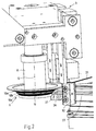
In Fig. 1 ist die erfindungsgemäße Verputzvorrichtung 3 im
Einsatz gezeigt. Eine im Schweißnahtbereich 23 befindliche
Schweißraupe 24 ist bei der hier gezeigten Stellung bereits
abgearbeitet.In Fig. 1, the
Die Verputzvorrichtung 3 besteht aus einem an einem Maschinengestellt
(nicht gezeigt) bewegbaren Arm, der an seinem unteren,
dem Rahmen 2 zugewandten Ende Anschläge 31, 32, einen Niederhalter
35, sowie das als Konturfräser 10 ausgestaltete Werkzeug
1 trägt. Die Antriebswelle 11 wird zum Beispiel über einen
Riemenantrieb durch einen Antriebsmotor in Rotation versetzt.The
Es wird nachfolgend oftmals von einem Rahmen 2 gesprochen,
wobei dieser auch als Rahmenteil 2 in gleichen Sinne auszulegen
ist, da die Erfindung bereits bei zwei miteinander verbundenen
Kunststoffprofilen 21, 22 einsetzbar ist. Der Übersichtlichkeit
halber ist aber nur der hier interessierende Eckbereich gezeigt,
die Erfindung ist aber sowohl auf einen Rahmen 2 wie
auch auf Rahmenteile anwendbar. It is often referred to below as a
Die Kunststoffprofile 21, 22 sind winklig, insbesondere rechtwinklig
verschweißt. Hierzu wurden diese zunächst auf Gehrung
geschnitten und an der Schweißnaht 23 verschweißt. Aufgrund des
Fügeprozesses bei der Herstellung des Rahmens 2 entsteht eine
sich nach außen herauswölbende Schweißraupe 24 entlang der
Schweißnaht 23, die möglichst optisch neutral zu entfernen ist.
Insbesondere für den Außeneckbereich 27 wird die erfindungsgemäße
Verputzvorrichtung vorgesehen, wenngleich diese hierauf
nicht in ihrer Anwendung beschränkt ist.The plastic profiles 21, 22 are angled, in particular at right angles
welded. These were first mitred
cut and welded to the
In Fig. 3 ist zunächst die Anordnung vor der Bearbeitung gezeigt.
Im Schweißnahtbereich 23 befindet sich zumindest im
Außeneckbereich 27 die abzuarbeitende Schweißraupe 24.In Fig. 3, first, the arrangement is shown prior to processing.
In the
Die Verputzvorrichtung ist in zwei rechtwinklig zueinander
orientierten Richtungen 33, 34 bewegbar. Günstigerweise ist
eine Bewegungskomponente hierbei parallel (Pfeil 34) zur durch
den Rahmen 2 beziehungsweise durch die Kunststoffprofile 21, 22
zusammengesetzten Rahmenteile definierte Rahmenebene und die
andere Bewegungskomponente hierzu rechtwinklig (angedeutet
durch den Pfeil 33). Für die Bewegung in die beiden Richtungen
33, 34 sind bevorzugt pneumatisch wirkende Arbeitszylinder vorgesehen,
die gegebenenfalls auch gleichzeitig als Dämpfer beim
Heranfahren der Anschläge/Niederhalter an den Rahmen dienen
können. Der Antrieb kann aber auch anders, zum Beispiel durch
Elektromotoren und dergleichen realisiert werden.The plastering device is in two perpendicular to each other
oriented
Die Verputzvorrichtung trägt an ihrem unteren Ende zwei winklig
zueinander angeordnete Anschläge 31, 32. Die winklige Anordnung
der Anschläge 31, 32 entspricht dabei dem Winkel wie die Kunststoffprofile
21, 22 im Rahmen 2 verschweißt sind.The plasterer carries at its lower end two angled
mutually arranged stops 31, 32. The angular arrangement
the
Zunächst wird die Verputzvorrichtung entlang des Pfeiles 34,
also parallel zur Rahmenebene herangeführt, bis beide Anschläge
31, 32 mit dem jeweiligen Kunststoffprofilen 21, 22 zur Anlage
kommen. Günstigerweise wird dabei eine Richtung der Bewegungskomponente
34 gewählt, die sowohl eine Annäherung des ersten
Anschlages 31 wie auch des zweiten Anschlages 32 an den Rahmen
2 ergeben. Zum Beispiel wird die Bewegungskomponente 34
parallel zur Gehrungsfläche beziehungsweise Schweißnaht 23
vorgesehen.First, the Verputzvorrichtung along the
Liegen die Anschläge 31, 32 an den Kunststoffprofilen 21, 22
an, so ist in der Regel die Verputzvorrichtung 3 noch zu hoch
und daher der Konturfräser 10 noch nicht im Eingriff am Rahmen.
Im zweiten Schritt wird dann eine Bewegung entlang der Bewegungskomponente
33 (rechtwinklig zur ersten Bewegungskomponente
34) durchgeführt, also die Verputzvorrichtung 3 abgesenkt, bis
der Niederhalter 35 auf der Rahmenoberfläche 25 aufliegt.If the stops 31, 32 on the plastic profiles 21, 22nd
on, so the
Dabei ist die Anordnung des Konturfräsers 10 bezüglich des
Niederhalters 35 sowie den beiden Anschlägen 31, 32 so gewählt,
daß wenn der Niederhalter 35 und die Anschläge 31, 32 auf den
Rahmen beziehungsweise mit den Kunststoffprofilen zusammenwirken,
also an diesen anliegen, der Konturfräser 10 exakt die
vorstehende Schweißraupe 24 abarbeitet. Hierzu ist vorgesehen,
daß diese Position natürlich entsprechend einstellbar ist, um
das gewünschte Arbeitsergebnis zu erreichen.In this case, the arrangement of the
Bei dieser Vorgehensweise wirkt der Niederhalter 35 als weiterer Anschlag in Richtung der Bewegung der Bewegungskomponente 33.In this procedure, the hold-down 35 acts as further stop in the direction of movement of the movement component 33rd
Da die Schweißnaht 23 entlang der Gehrungsfläche verläuft, die
in einem Winkel, in der Regel dem hälftigen Verbindungswinkel
der beiden Kunststoffprofile verläuft, entspricht die äußere
Kontur beziehungsweise Oberflächenverlauf 26 der Profile 21, 22
im Schweißnahtbereich nicht der Kontur des Profilquerschnittes.
Die Ausgestaltung der Konturfräsers 10 ist aber so geschaffen,
daß sie dem Oberflächenverlauf 26 des Kunststoffprofiles 21, 22
im Schweißnahtbereich 23 entspricht. Dadurch wird ein optimales
Abtragen der über die Schweißnaht 23 vorstehenden Schweißraupe
24 erreicht, ohne die Oberfläche weiter zu verletzen.Since the
Der Konturenverlauf des Konturfräsers 10, der dem Oberflächenverlauf
26 des Kunststoffprofiles 21, 22 dem Schweißnahtbereich
entspricht, wird durch eine Anordnung von Schneiden am Umfang
eines den Konturfräser 10 bildenden Grundkörpers gebildet. Der
Grundkörper weist entsprechend dem Oberflächenverlauf 26 des
Kunststoffprofiles 21, 22 an seinem Umfang Abstufungen 10a
und/oder Vorsprüngen 10b auf, so das der Grundkörper über seine
Länge unterschiedlich dick ist. Zumindest jedem Abschnitt des
Grundkörpers ist eine Schneide zugeordnet, wobei die Schneide
dabei eine gerade oder gekrümmte Kante aufweisen kann. Eine
gerade Kante der Schneide erzeugt im Außeneckbereich 27 des
Kunststoffprofiles 21, 22 ebenfalls eine gerade Kante und eine
gekrümmte Schneide eine gewölbte Kante. Mit der Ausbildung der
Schneiden kann die Kontur der Außeneckverbindung 27 exakt
profiliert werden.The contour of the
Nach einer nicht dargestellten Variante der Erfindung ist der
Grundkörper aus einzelnen Scheiben unterschiedlichen Durchmessers
zusammengesetzt. Jede Scheibe trägt zumindest eine
Schneide, die das Kunststoffprofil 21, 22 bearbeitet. Vorteilhafterweise
sind die Schneiden über den gesamten Umfang des
Grundkörpers bzw. der Scheiben angeordnet, so daß ein kontinuierliches
Abtragen der Schweißraupe 24 gewährleistet ist.According to a variant of the invention, not shown is the
Basic body of individual disks of different diameters
composed. Each disc carries at least one
Cutting edge, which processes the
Es ist vorgesehen, daß an der Verputzvorrichtung 3 ein Antriebsmotor
für den Konturfräser 10 vorgesehen ist. Der Antriebsmotor
läßt den Konturfräser 10 um die in diesem Beispiel
vertikal verlaufende, beziehungsweise rechtwinklig zur Rahmenebene
stehende Rotationsachse 12 rotieren.It is envisaged that on the
Die jetzt mit der Anmeldung und später eingereichten Ansprüche sind Versuche zur Formulierung ohne Präjudiz für die Erzielung weitergehenden Schutzes.The now with the application and later claims are attempts to formulate without prejudice to the achievement further protection.
Sollte sich hier bei näherer Prüfung, insbesondere auch des einschlägigen Standes der Technik, ergeben, daß das eine oder andere Merkmal für das Ziel der Erfindung zwar günstig, nicht aber entscheidend wichtig ist, so wird selbstverständlich schon jetzt eine Formulierung angestrebt, die ein solches Merkmal, insbesondere im Hauptanspruch, nicht mehr aufweist.Should be here on closer examination, especially the pertinent art, that the one or other feature for the aim of the invention, although favorable, not but it is crucial, so it goes without saying now seeking a formulation that is such a feature especially in the main claim, no longer has.
Die in den abhängigen Ansprüchen angeführten Rückbeziehungen weisen auf die weitere Ausbildung des Gegenstandes des Hauptanspruches durch die Merkmale des jeweiligen Unteranspruches hin. Jedoch sind diese nicht als ein Verzicht auf die Erzielung eines selbständigen, gegenständlichen Schutzes für die Merkmale der rückbezogenen Unteransprüche zu verstehen.The relationships given in the dependent claims point to the further development of the subject of the main claim by the features of the respective subclaim out. However, these are not as a waiver of achievement an independent, objective protection for the characteristics to understand the dependent claims.
Merkmale, die bislang nur in der Beschreibung offenbart wurden, können im Laufe des Verfahrens als von erfindungswesentlicher Bedeutung, zum Beispiel zur Abgrenzung vom Stand der Technik beansprucht werden.Features that have so far been disclosed only in the specification, can in the course of the process as essential to the invention Meaning, for example, to differentiate from the prior art be claimed.
Merkmale, die nur in der Beschreibung offenbart wurden, oder auch Einzelmerkmale aus Ansprüchen, die eine Mehrzahl von Merkmalen umfassen, können jederzeit zur Abgrenzung vom Stande der Technik in den ersten Anspruch übernommen werden, und zwar auch dann, wenn solche Merkmale im Zusammenhang mit anderen Merkmalen erwähnt wurden beziehungsweise im Zusammenhang mit anderen Merkmalen besonders günstige Ergebnisse erreichen.Features that have been disclosed only in the description, or also individual features from claims that have a plurality of features can always be used to differentiate from the state of Technique can be adopted in the first claim, and indeed then, if such features are related to other characteristics mentioned or in connection with others Characteristics achieve particularly favorable results.
Claims (10)
Priority Applications (1)
| Application Number | Priority Date | Filing Date | Title |
|---|---|---|---|
| PL04028701T PL1537970T3 (en) | 2003-12-04 | 2004-12-03 | Deburring device |
Applications Claiming Priority (2)
| Application Number | Priority Date | Filing Date | Title |
|---|---|---|---|
| DE20318942U DE20318942U1 (en) | 2003-12-04 | 2003-12-04 | trimming device |
| DE20318942U | 2003-12-04 |
Publications (3)
| Publication Number | Publication Date |
|---|---|
| EP1537970A2 true EP1537970A2 (en) | 2005-06-08 |
| EP1537970A3 EP1537970A3 (en) | 2006-11-15 |
| EP1537970B1 EP1537970B1 (en) | 2010-04-14 |
Family
ID=34442560
Family Applications (1)
| Application Number | Title | Priority Date | Filing Date |
|---|---|---|---|
| EP04028701A Active EP1537970B1 (en) | 2003-12-04 | 2004-12-03 | Deburring device |
Country Status (6)
| Country | Link |
|---|---|
| US (1) | US20050141974A1 (en) |
| EP (1) | EP1537970B1 (en) |
| AT (1) | ATE464168T1 (en) |
| CA (1) | CA2488998A1 (en) |
| DE (2) | DE20318942U1 (en) |
| PL (1) | PL1537970T3 (en) |
Cited By (2)
| Publication number | Priority date | Publication date | Assignee | Title |
|---|---|---|---|---|
| CN103302357A (en) * | 2013-05-29 | 2013-09-18 | 皮丕军 | Triple-head chamfering machine and control program thereof |
| CN111036968A (en) * | 2019-12-30 | 2020-04-21 | 武昌船舶重工集团有限公司 | Weld joint back chipping processing equipment |
Families Citing this family (6)
| Publication number | Priority date | Publication date | Assignee | Title |
|---|---|---|---|---|
| DE102005062133A1 (en) * | 2005-12-23 | 2007-06-28 | Willi Stürtz Maschinenbau GmbH | Method for editing window frames |
| US7784161B2 (en) * | 2006-03-27 | 2010-08-31 | Rotox Gmbh | Device for machining the corner area of a frame welded together out of profiled pieces |
| ITMO20060146A1 (en) * | 2006-05-10 | 2007-11-11 | Emmegi Spa | MACHINE TOOL |
| EP2431006A1 (en) * | 2010-09-16 | 2012-03-21 | 3M Innovative Properties Company | A method of making a dental restoration |
| DE102019123144A1 (en) * | 2019-08-29 | 2021-03-04 | Rotox Besitz- Und Verwaltungsgesellschaft Mbh | Device for processing window or door frames welded from profile pieces |
| BE1028581B1 (en) * | 2020-09-04 | 2022-04-04 | Sobinco Fa | Tool for machining the sash of a window or door |
Citations (4)
| Publication number | Priority date | Publication date | Assignee | Title |
|---|---|---|---|---|
| DE7821618U1 (en) | 1978-07-19 | 1979-04-05 | Radermacher, Richard, 5451 Horhausen | DEVICE FOR SMOOTHING CORNER-WELDED FRAME CORNER PROFILES OF PLASTIC DOORS AND WINDOWS |
| EP0350832A1 (en) | 1988-07-12 | 1990-01-17 | Bernhard Eisenbach | Outside corner-dressing device for window frames or the like |
| DE4018145A1 (en) | 1990-06-06 | 1991-12-12 | Bernd Eisenbach | Plastics window frame weld cleaner - has tool support with contour miller and milling tools set according to the frame profile |
| DE9305046U1 (en) | 1993-04-02 | 1993-09-09 | Lemuth Praezisionsteile Gmbh | Device for cleaning the welding beads created when welding plastic profiles |
Family Cites Families (17)
| Publication number | Priority date | Publication date | Assignee | Title |
|---|---|---|---|---|
| US783946A (en) * | 1903-10-01 | 1905-02-28 | Richard K Gregory | Machine for making laths. |
| US1630173A (en) * | 1926-11-06 | 1927-05-24 | Dumont Joseph | Double carving cutter |
| US2751942A (en) * | 1952-04-10 | 1956-06-26 | Porter Cable Machine Co | Cutter arbor shaft for portable power operated tools |
| US3237275A (en) * | 1963-12-12 | 1966-03-01 | Burton E Middleton | Cutting tools |
| US3708129A (en) * | 1971-01-07 | 1973-01-02 | Munson Mill Machinery Co | Cutter machine |
| US3986543A (en) * | 1975-07-21 | 1976-10-19 | Kimball International, Inc. | Rotary cutter knife |
| DE3020739C2 (en) * | 1980-05-31 | 1986-08-14 | Bernhard 6259 Brechen Eisenbach | Device for removing protruding weld beads or the like. |
| DE3711487A1 (en) * | 1986-11-12 | 1988-10-13 | Bernhard Eisenbach | Removal of welding bead from window frames - involves machine with cutting tools mounted on vertical slides |
| DE3727136A1 (en) * | 1987-08-14 | 1989-02-23 | Urban Maschinenbau | METHOD AND DEVICE FOR MACHINING THE CORNER CONNECTIONS OF FRAME FROM PLASTIC PROFILES |
| DE4018290A1 (en) * | 1990-06-07 | 1991-12-12 | Bernd Eisenbach | DEVICE FOR MACHINING WINDOW FRAMES OR THE LIKE |
| DE9106839U1 (en) * | 1990-11-28 | 1991-09-26 | Willi Stuertz Maschinenbau Gmbh, 5466 Neustadt, De | |
| CA2119308C (en) * | 1994-03-17 | 1996-12-24 | Walter Louis Grassi | Corner cleaning machine |
| DE19724699A1 (en) * | 1997-06-12 | 1998-12-17 | Bernhard Eisenbach | Dressing tool arrangement for cleaning up the beads at the corners of welded profiles forming windows and doors |
| US5996659A (en) * | 1998-01-09 | 1999-12-07 | Burgess; Michael | Matched pair of plywood edge-banding router bits |
| US6164351A (en) * | 2000-01-05 | 2000-12-26 | Triangle Pacific Corporation | Precision-balanced cutter head and method |
| DE20109451U1 (en) * | 2001-04-12 | 2002-08-22 | Urban Gmbh & Co Maschb Kg | Device for processing plastic profiles for window frames or the like. |
| US7219706B2 (en) * | 2002-09-06 | 2007-05-22 | Key Knife, Inc. | Apparatus having adjustable saws for wood cutting |
-
2003
- 2003-12-04 DE DE20318942U patent/DE20318942U1/en not_active Expired - Lifetime
-
2004
- 2004-12-02 US US11/001,095 patent/US20050141974A1/en not_active Abandoned
- 2004-12-03 DE DE502004011025T patent/DE502004011025D1/en active Active
- 2004-12-03 EP EP04028701A patent/EP1537970B1/en active Active
- 2004-12-03 PL PL04028701T patent/PL1537970T3/en unknown
- 2004-12-03 AT AT04028701T patent/ATE464168T1/en not_active IP Right Cessation
- 2004-12-03 CA CA002488998A patent/CA2488998A1/en not_active Abandoned
Patent Citations (4)
| Publication number | Priority date | Publication date | Assignee | Title |
|---|---|---|---|---|
| DE7821618U1 (en) | 1978-07-19 | 1979-04-05 | Radermacher, Richard, 5451 Horhausen | DEVICE FOR SMOOTHING CORNER-WELDED FRAME CORNER PROFILES OF PLASTIC DOORS AND WINDOWS |
| EP0350832A1 (en) | 1988-07-12 | 1990-01-17 | Bernhard Eisenbach | Outside corner-dressing device for window frames or the like |
| DE4018145A1 (en) | 1990-06-06 | 1991-12-12 | Bernd Eisenbach | Plastics window frame weld cleaner - has tool support with contour miller and milling tools set according to the frame profile |
| DE9305046U1 (en) | 1993-04-02 | 1993-09-09 | Lemuth Praezisionsteile Gmbh | Device for cleaning the welding beads created when welding plastic profiles |
Cited By (3)
| Publication number | Priority date | Publication date | Assignee | Title |
|---|---|---|---|---|
| CN103302357A (en) * | 2013-05-29 | 2013-09-18 | 皮丕军 | Triple-head chamfering machine and control program thereof |
| CN103302357B (en) * | 2013-05-29 | 2016-07-06 | 陈晓慧 | A kind of control method of three bevelers |
| CN111036968A (en) * | 2019-12-30 | 2020-04-21 | 武昌船舶重工集团有限公司 | Weld joint back chipping processing equipment |
Also Published As
| Publication number | Publication date |
|---|---|
| DE502004011025D1 (en) | 2010-05-27 |
| PL1537970T3 (en) | 2010-08-31 |
| CA2488998A1 (en) | 2005-06-04 |
| EP1537970B1 (en) | 2010-04-14 |
| ATE464168T1 (en) | 2010-04-15 |
| US20050141974A1 (en) | 2005-06-30 |
| EP1537970A3 (en) | 2006-11-15 |
| DE20318942U1 (en) | 2005-04-14 |
Similar Documents
| Publication | Publication Date | Title |
|---|---|---|
| DE102010061321A1 (en) | Method for milling a recess in a workpiece and workpiece with a recess | |
| EP1537970B1 (en) | Deburring device | |
| DE102016104806A1 (en) | Method for connecting profile pieces | |
| EP3674065A1 (en) | Method and device for welding profile bars | |
| EP1543906A1 (en) | Machining unit for treatment of corner joints of frames of welded profiles | |
| DE202017102951U1 (en) | trimming device | |
| EP0909602B1 (en) | Cleaning device for window or door frames | |
| EP1800783A1 (en) | Cutting table and method for cutting profile sections | |
| DE2415006C3 (en) | Process for the production of window frames with glass retaining bead made of wood and device for carrying out the process | |
| DE3137819C2 (en) | Device for cutting off weld burrs | |
| DE3422101C2 (en) | ||
| DE3813852C2 (en) | ||
| DE19905414C2 (en) | Device for cutting and notching profiles | |
| EP1430996B1 (en) | Machining unit for deburring corner joints of frames of welded plastic profiles | |
| EP0978339B1 (en) | Device for cutting profiles for windows or doors | |
| EP1297923B2 (en) | Machining unit for deburring of corner joints of window or door frames of welded plastic profiles | |
| DE4409813A1 (en) | Apparatus for cutting to size bar-shaped workpieces, in particular glazing bars for windows or doors | |
| DE2722283C2 (en) | Cutting tool for cutting a groove | |
| DE4107946A1 (en) | Method of milling cross grain or end grain of timber batten widths - involves pair of cutter heads at right angles to work piece, traversing first from one side and then other | |
| EP4350113A2 (en) | Device and method for the production of an element | |
| DE3036630C2 (en) | Device for removing the weld beads at corner connections | |
| DE2236087C3 (en) | Device for processing the butt parts of parts butt-welded from profiles | |
| DE2628681A1 (en) | Corner joints for window or door frames - with removal of beads at corners from both sides of frame | |
| DE3310307A1 (en) | Device for trimming the welding bead on window frames or the like | |
| DE19856088A1 (en) | Window frame production process, involving milling in groove using disk milling tool |
Legal Events
| Date | Code | Title | Description |
|---|---|---|---|
| PUAI | Public reference made under article 153(3) epc to a published international application that has entered the european phase |
Free format text: ORIGINAL CODE: 0009012 |
|
| AK | Designated contracting states |
Kind code of ref document: A2 Designated state(s): AT BE BG CH CY CZ DE DK EE ES FI FR GB GR HU IE IS IT LI LT LU MC NL PL PT RO SE SI SK TR |
|
| AX | Request for extension of the european patent |
Extension state: AL BA HR LV MK YU |
|
| PUAL | Search report despatched |
Free format text: ORIGINAL CODE: 0009013 |
|
| AK | Designated contracting states |
Kind code of ref document: A3 Designated state(s): AT BE BG CH CY CZ DE DK EE ES FI FR GB GR HU IE IS IT LI LT LU MC NL PL PT RO SE SI SK TR |
|
| AX | Request for extension of the european patent |
Extension state: AL BA HR LV MK YU |
|
| 17P | Request for examination filed |
Effective date: 20070505 |
|
| 17Q | First examination report despatched |
Effective date: 20070606 |
|
| AKX | Designation fees paid |
Designated state(s): AT BE BG CH CY CZ DE DK EE ES FI FR GB GR HU IE IS IT LI LT LU MC NL PL PT RO SE SI SK TR |
|
| GRAP | Despatch of communication of intention to grant a patent |
Free format text: ORIGINAL CODE: EPIDOSNIGR1 |
|
| GRAS | Grant fee paid |
Free format text: ORIGINAL CODE: EPIDOSNIGR3 |
|
| GRAA | (expected) grant |
Free format text: ORIGINAL CODE: 0009210 |
|
| AK | Designated contracting states |
Kind code of ref document: B1 Designated state(s): AT BE BG CH CY CZ DE DK EE ES FI FR GB GR HU IE IS IT LI LT LU MC NL PL PT RO SE SI SK TR |
|
| REG | Reference to a national code |
Ref country code: GB Ref legal event code: FG4D Free format text: NOT ENGLISH |
|
| REG | Reference to a national code |
Ref country code: CH Ref legal event code: EP |
|
| REG | Reference to a national code |
Ref country code: IE Ref legal event code: FG4D Free format text: LANGUAGE OF EP DOCUMENT: GERMAN |
|
| REF | Corresponds to: |
Ref document number: 502004011025 Country of ref document: DE Date of ref document: 20100527 Kind code of ref document: P |
|
| REG | Reference to a national code |
Ref country code: NL Ref legal event code: VDEP Effective date: 20100414 |
|
| REG | Reference to a national code |
Ref country code: PL Ref legal event code: T3 |
|
| LTIE | Lt: invalidation of european patent or patent extension |
Effective date: 20100414 |
|
| PG25 | Lapsed in a contracting state [announced via postgrant information from national office to epo] |
Ref country code: LT Free format text: LAPSE BECAUSE OF FAILURE TO SUBMIT A TRANSLATION OF THE DESCRIPTION OR TO PAY THE FEE WITHIN THE PRESCRIBED TIME-LIMIT Effective date: 20100414 Ref country code: SE Free format text: LAPSE BECAUSE OF FAILURE TO SUBMIT A TRANSLATION OF THE DESCRIPTION OR TO PAY THE FEE WITHIN THE PRESCRIBED TIME-LIMIT Effective date: 20100414 Ref country code: NL Free format text: LAPSE BECAUSE OF FAILURE TO SUBMIT A TRANSLATION OF THE DESCRIPTION OR TO PAY THE FEE WITHIN THE PRESCRIBED TIME-LIMIT Effective date: 20100414 Ref country code: ES Free format text: LAPSE BECAUSE OF FAILURE TO SUBMIT A TRANSLATION OF THE DESCRIPTION OR TO PAY THE FEE WITHIN THE PRESCRIBED TIME-LIMIT Effective date: 20100725 |
|
| REG | Reference to a national code |
Ref country code: IE Ref legal event code: FD4D |
|
| PG25 | Lapsed in a contracting state [announced via postgrant information from national office to epo] |
Ref country code: IS Free format text: LAPSE BECAUSE OF FAILURE TO SUBMIT A TRANSLATION OF THE DESCRIPTION OR TO PAY THE FEE WITHIN THE PRESCRIBED TIME-LIMIT Effective date: 20100814 Ref country code: FI Free format text: LAPSE BECAUSE OF FAILURE TO SUBMIT A TRANSLATION OF THE DESCRIPTION OR TO PAY THE FEE WITHIN THE PRESCRIBED TIME-LIMIT Effective date: 20100414 Ref country code: SI Free format text: LAPSE BECAUSE OF FAILURE TO SUBMIT A TRANSLATION OF THE DESCRIPTION OR TO PAY THE FEE WITHIN THE PRESCRIBED TIME-LIMIT Effective date: 20100414 |
|
| PG25 | Lapsed in a contracting state [announced via postgrant information from national office to epo] |
Ref country code: CY Free format text: LAPSE BECAUSE OF FAILURE TO SUBMIT A TRANSLATION OF THE DESCRIPTION OR TO PAY THE FEE WITHIN THE PRESCRIBED TIME-LIMIT Effective date: 20100421 Ref country code: GR Free format text: LAPSE BECAUSE OF FAILURE TO SUBMIT A TRANSLATION OF THE DESCRIPTION OR TO PAY THE FEE WITHIN THE PRESCRIBED TIME-LIMIT Effective date: 20100715 |
|
| PG25 | Lapsed in a contracting state [announced via postgrant information from national office to epo] |
Ref country code: PT Free format text: LAPSE BECAUSE OF FAILURE TO SUBMIT A TRANSLATION OF THE DESCRIPTION OR TO PAY THE FEE WITHIN THE PRESCRIBED TIME-LIMIT Effective date: 20100816 Ref country code: DK Free format text: LAPSE BECAUSE OF FAILURE TO SUBMIT A TRANSLATION OF THE DESCRIPTION OR TO PAY THE FEE WITHIN THE PRESCRIBED TIME-LIMIT Effective date: 20100414 Ref country code: IE Free format text: LAPSE BECAUSE OF FAILURE TO SUBMIT A TRANSLATION OF THE DESCRIPTION OR TO PAY THE FEE WITHIN THE PRESCRIBED TIME-LIMIT Effective date: 20100414 Ref country code: EE Free format text: LAPSE BECAUSE OF FAILURE TO SUBMIT A TRANSLATION OF THE DESCRIPTION OR TO PAY THE FEE WITHIN THE PRESCRIBED TIME-LIMIT Effective date: 20100414 |
|
| PLBE | No opposition filed within time limit |
Free format text: ORIGINAL CODE: 0009261 |
|
| STAA | Information on the status of an ep patent application or granted ep patent |
Free format text: STATUS: NO OPPOSITION FILED WITHIN TIME LIMIT |
|
| PG25 | Lapsed in a contracting state [announced via postgrant information from national office to epo] |
Ref country code: SK Free format text: LAPSE BECAUSE OF FAILURE TO SUBMIT A TRANSLATION OF THE DESCRIPTION OR TO PAY THE FEE WITHIN THE PRESCRIBED TIME-LIMIT Effective date: 20100414 Ref country code: RO Free format text: LAPSE BECAUSE OF FAILURE TO SUBMIT A TRANSLATION OF THE DESCRIPTION OR TO PAY THE FEE WITHIN THE PRESCRIBED TIME-LIMIT Effective date: 20100414 |
|
| 26N | No opposition filed |
Effective date: 20110117 |
|
| PG25 | Lapsed in a contracting state [announced via postgrant information from national office to epo] |
Ref country code: MC Free format text: LAPSE BECAUSE OF NON-PAYMENT OF DUE FEES Effective date: 20101231 |
|
| REG | Reference to a national code |
Ref country code: CH Ref legal event code: PL |
|
| PG25 | Lapsed in a contracting state [announced via postgrant information from national office to epo] |
Ref country code: LI Free format text: LAPSE BECAUSE OF NON-PAYMENT OF DUE FEES Effective date: 20101231 Ref country code: CH Free format text: LAPSE BECAUSE OF NON-PAYMENT OF DUE FEES Effective date: 20101231 |
|
| PG25 | Lapsed in a contracting state [announced via postgrant information from national office to epo] |
Ref country code: AT Free format text: LAPSE BECAUSE OF NON-PAYMENT OF DUE FEES Effective date: 20101203 |
|
| REG | Reference to a national code |
Ref country code: AT Ref legal event code: MM01 Ref document number: 464168 Country of ref document: AT Kind code of ref document: T Effective date: 20101203 |
|
| PG25 | Lapsed in a contracting state [announced via postgrant information from national office to epo] |
Ref country code: BG Free format text: LAPSE BECAUSE OF FAILURE TO SUBMIT A TRANSLATION OF THE DESCRIPTION OR TO PAY THE FEE WITHIN THE PRESCRIBED TIME-LIMIT Effective date: 20100414 Ref country code: HU Free format text: LAPSE BECAUSE OF FAILURE TO SUBMIT A TRANSLATION OF THE DESCRIPTION OR TO PAY THE FEE WITHIN THE PRESCRIBED TIME-LIMIT Effective date: 20101015 Ref country code: LU Free format text: LAPSE BECAUSE OF NON-PAYMENT OF DUE FEES Effective date: 20101203 |
|
| PGFP | Annual fee paid to national office [announced via postgrant information from national office to epo] |
Ref country code: CZ Payment date: 20121126 Year of fee payment: 9 |
|
| PGFP | Annual fee paid to national office [announced via postgrant information from national office to epo] |
Ref country code: IT Payment date: 20121222 Year of fee payment: 9 Ref country code: PL Payment date: 20121019 Year of fee payment: 9 Ref country code: TR Payment date: 20121203 Year of fee payment: 9 Ref country code: GB Payment date: 20121218 Year of fee payment: 9 |
|
| PGFP | Annual fee paid to national office [announced via postgrant information from national office to epo] |
Ref country code: BE Payment date: 20121217 Year of fee payment: 9 Ref country code: FR Payment date: 20130123 Year of fee payment: 9 |
|
| PG25 | Lapsed in a contracting state [announced via postgrant information from national office to epo] |
Ref country code: BG Free format text: LAPSE BECAUSE OF FAILURE TO SUBMIT A TRANSLATION OF THE DESCRIPTION OR TO PAY THE FEE WITHIN THE PRESCRIBED TIME-LIMIT Effective date: 20100714 |
|
| BERE | Be: lapsed |
Owner name: URBAN G.M.B.H. & CO. MASCHINENBAU KG Effective date: 20131231 |
|
| GBPC | Gb: european patent ceased through non-payment of renewal fee |
Effective date: 20131203 |
|
| PG25 | Lapsed in a contracting state [announced via postgrant information from national office to epo] |
Ref country code: CZ Free format text: LAPSE BECAUSE OF NON-PAYMENT OF DUE FEES Effective date: 20131203 |
|
| REG | Reference to a national code |
Ref country code: FR Ref legal event code: ST Effective date: 20140829 |
|
| PG25 | Lapsed in a contracting state [announced via postgrant information from national office to epo] |
Ref country code: BE Free format text: LAPSE BECAUSE OF NON-PAYMENT OF DUE FEES Effective date: 20131231 |
|
| PG25 | Lapsed in a contracting state [announced via postgrant information from national office to epo] |
Ref country code: FR Free format text: LAPSE BECAUSE OF NON-PAYMENT OF DUE FEES Effective date: 20131231 Ref country code: GB Free format text: LAPSE BECAUSE OF NON-PAYMENT OF DUE FEES Effective date: 20131203 |
|
| PG25 | Lapsed in a contracting state [announced via postgrant information from national office to epo] |
Ref country code: PL Free format text: LAPSE BECAUSE OF NON-PAYMENT OF DUE FEES Effective date: 20131203 |
|
| REG | Reference to a national code |
Ref country code: PL Ref legal event code: LAPE |
|
| PG25 | Lapsed in a contracting state [announced via postgrant information from national office to epo] |
Ref country code: IT Free format text: LAPSE BECAUSE OF NON-PAYMENT OF DUE FEES Effective date: 20131231 |
|
| PG25 | Lapsed in a contracting state [announced via postgrant information from national office to epo] |
Ref country code: TR Free format text: LAPSE BECAUSE OF NON-PAYMENT OF DUE FEES Effective date: 20131203 |
|
| PG25 | Lapsed in a contracting state [announced via postgrant information from national office to epo] |
Ref country code: IT Free format text: LAPSE BECAUSE OF NON-PAYMENT OF DUE FEES Effective date: 20131203 |
|
| REG | Reference to a national code |
Ref country code: DE Ref legal event code: R082 Ref document number: 502004011025 Country of ref document: DE Representative=s name: PATENTANWAELTE OLBRICHT, BUCHHOLD, KEULERTZ PA, DE |
|
| REG | Reference to a national code |
Ref country code: DE Ref legal event code: R082 Ref document number: 502004011025 Country of ref document: DE Representative=s name: PATENTANWAELTE OLBRICHT, BUCHHOLD, KEULERTZ PA, DE |
|
| PGFP | Annual fee paid to national office [announced via postgrant information from national office to epo] |
Ref country code: DE Payment date: 20231231 Year of fee payment: 20 |