EP1536634B1 - Optical apparatus and camera system - Google Patents
Optical apparatus and camera system Download PDFInfo
- Publication number
- EP1536634B1 EP1536634B1 EP04257301.4A EP04257301A EP1536634B1 EP 1536634 B1 EP1536634 B1 EP 1536634B1 EP 04257301 A EP04257301 A EP 04257301A EP 1536634 B1 EP1536634 B1 EP 1536634B1
- Authority
- EP
- European Patent Office
- Prior art keywords
- preset
- zoom
- drive
- speed
- section
- Prior art date
- Legal status (The legal status is an assumption and is not a legal conclusion. Google has not performed a legal analysis and makes no representation as to the accuracy of the status listed.)
- Expired - Lifetime
Links
- 230000003287 optical effect Effects 0.000 title claims description 82
- 238000012545 processing Methods 0.000 claims description 38
- 230000001360 synchronised effect Effects 0.000 claims description 10
- 238000000034 method Methods 0.000 description 30
- 230000006870 function Effects 0.000 description 16
- 238000001514 detection method Methods 0.000 description 14
- 238000006243 chemical reaction Methods 0.000 description 9
- 238000011156 evaluation Methods 0.000 description 5
- 238000010586 diagram Methods 0.000 description 4
- 230000004044 response Effects 0.000 description 4
- 238000003384 imaging method Methods 0.000 description 2
- 230000001419 dependent effect Effects 0.000 description 1
- 238000011161 development Methods 0.000 description 1
- 230000018109 developmental process Effects 0.000 description 1
- 238000012986 modification Methods 0.000 description 1
- 230000004048 modification Effects 0.000 description 1
Images


Classifications
-
- H—ELECTRICITY
- H04—ELECTRIC COMMUNICATION TECHNIQUE
- H04N—PICTORIAL COMMUNICATION, e.g. TELEVISION
- H04N23/00—Cameras or camera modules comprising electronic image sensors; Control thereof
- H04N23/60—Control of cameras or camera modules
- H04N23/66—Remote control of cameras or camera parts, e.g. by remote control devices
- H04N23/663—Remote control of cameras or camera parts, e.g. by remote control devices for controlling interchangeable camera parts based on electronic image sensor signals
-
- H—ELECTRICITY
- H04—ELECTRIC COMMUNICATION TECHNIQUE
- H04N—PICTORIAL COMMUNICATION, e.g. TELEVISION
- H04N23/00—Cameras or camera modules comprising electronic image sensors; Control thereof
- H04N23/60—Control of cameras or camera modules
- H04N23/67—Focus control based on electronic image sensor signals
Definitions
- the present invention relates to an optical apparatus (lens apparatus) and a camera system usable in television cameras or video cameras or the like, and more particularly, to an optical apparatus and a camera system having a zoom lens system etc. which are usable in an ENC camera etc.
- an image-taking method in which a zoom lens unit is moved with a predetermined, constant speed corresponse to a predetermined zoom magnification for image-taking.
- an image-taking method having the following function. That is, an arbitrary zoom position is stored in memory in advance as a preset position and an arbitrary zoom lens drive speed is stored in memory in advance as a preset speed.
- a switch is turned on during image-taking, a zoom lens unit is moved to the preset position with the preset speed.
- this preset function is referred to as "position preset zoom control”.
- an image-taking method in which a zoom lens unit is moved in a predetermined zoom direction with a predetermined speed for image-taking.
- an image-taking method having the following function. That is, an arbitrary zoom lens drive direction is stored in memory in advance as a preset direction, an arbitrary zoom lens drive speed is stored in memory in advance as a preset speed, and when a switch is turned on during image-taking, the zoom lens unit is moved in the preset direction with the preset speed.
- this preset function is referred to as "speed preset zoom control”.
- position preset zoom control and "speed preset zoom control”
- a preset position, a preset speed, and a preset direction must be stored in a storage section.
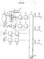
- a storing method and an operation method of the preset position, speed, and direction will be explained in reference to FIG. 6 .
- reference numeral 1 denotes a zoom control switch which is controlled by user
- reference numeral 2 denotes an instruction signal generating section which generates an instruction signal to instruct a drive direction and a drive speed (which may be replaced by a drive amount and a drive position) proportional to an operation amount of the zoom control switch 1 in order to electrically drive a zoom lens optical system 7 which will be described below.
- Reference numeral 3 denotes a zoom speed variable volume which varies the drive speed of the below-described zoom lens optical system 7 in response to the operation amount of the zoom control switch 1
- reference numeral 4 denotes an instruction signal calculation section which performs signal level and shift conversion for inputting the instruction signal into a below-mentioned A/D converter 5
- reference numeral 5 denotes the A/D converter which converts an analog signal outputted from the instruction signal calculation section 4 to a digital signal.
- Reference numeral 6 denotes a CPU which is responsible for the drive of a preset function
- reference character 6a denotes a storage section (memory), installed in the CPU 6, which can store the preset position, the preset speed, etc.
- reference numeral 7 denotes a zoom lens optical system which performs zooming of a lens apparatus.
- Reference numeral 8 denotes a D/A converter which converts a digital signal from the CPU 6 as the instruction signal outputted for driving the zoom lens optical system 7 to an analog signal
- reference numeral 9 denotes the instruction signal calculation section which performs signal level and shift conversion of the instruction signal outputted from the D/A converter 8.
- Reference numeral 10 denotes an instruction signal switching section which switches the drive of the zoom lens optical system 7 from the zoom control switch 1, or from the CPU 6, reference numeral 11 denotes an electric power amplifier which drives a below-mentioned motor 12, reference numeral 12 denotes the motor which drives the zoom lens optical system 7, and reference numeral 13 denotes a speed signal detection section which outputs a speed signal in accordance with a drive speed of the zoom lens optical system 7.
- Reference numeral 14 denotes a speed signal calculation section which performs signal level and shift conversion for inputting the speed signal into a below-mentioned A/D converter 15, and reference numeral 15 denotes an A/D converter which converts an analog signal outputted from the speed signal calculation section 14 to a digital signal.
- Reference numeral 16 denotes a position signal detection section which outputs a position signal corresponding to a position of the zoom lens optical system 7
- reference numeral 17 denotes a position signal calculation section which performs signal level and shift conversion for inputting a position signal into a below-mentioned A/D converter 18.
- Reference numeral 18 denotes an A/D converter which converts an analog signal outputted from the position signal calculation section 17 to a digital signal
- reference numeral 20 denotes a position preset zoom switch which instructs the start or end of the preset drive of position preset zoom.
- Reference numeral 22 denotes a speed preset zoom switch which instructs the start or end of the preset drive of speed preset zoom
- reference numeral 24 denotes a memory switch which instructs the memory information regarding the preset position, preset speed and preset direction of the various functions mentioned above.
- the memory setting procedure of the preset position will be explained.
- the position required for the zoom lens optical system 7 can be detected by inputting the output from the position signal detection section 16 into the CPU 6 via the position signal calculation section 17 and the A/D converter 18.
- an image-taker moves in advance the zoom lens optical system 7 to a desired preset position. Then, while the memory switch is on, the position of the zoom lens optical system 7 (the actual position detected via the position signal detection section 16) at the time when the position preset zoom switch 20 is switched from OFF to ON is stored in the CPU 6 as a preset position.
- the actual drive speed required for the zoom lens optical system 7 can be detected by inputting the output from the speed detection section 13 into the CPU 6 via the speed signal calculation section 14 and the A/D converter 15.
- the user operates the zoom control switch 1. While the zoom lens optical system 7 is in operation with a preset speed prepared in advance, the drive speed of the zoom lens optical system 7 (the actual drive speed of the zoom lens optical system 7 detected via the speed signal detection section 13) at the time when the memory switch 24 is switched from OFF to ON is stored in the CPU 6 as a preset speed.
- the user operates the zoom control switch 1. While the zoom lens optical system 7 is in operation with a preset speed prepared in advance and in a preset direction prepared in advance, the drive speed and direction of the zoom lens optical system 7 (actual drive speed and actual drive direction of the zoom lens optical system 7 detected via the A/D converter 15) at the time when the memory switch is switched from OFF to ON are stored in the CPU 6 as a preset speed and a preset direction.
- the present position of the zoom lens optical system 7 is detected by inputting the output from the position signal detection section 16 into the CPU 6 via the position signal calculation section 17 and the A/D converter 18 and compared with a stored preset position.
- the instruction signal from the CPU 6, which is calculated so as to drive with the preset speed is inputted into the electric power amplifier 11 via the D/A converter 8, the instruction signal calculation section 9, and the A side of the instruction signal switching section 10, and after amplified to a predetermined level by the electric power amplifier 11, it is inputted into the motor 12.
- the motor 12 starts driving, and the zoom lens optical system 7 also starts driving. And, when the position of the zoom lens optical system 7 coincides with the preset position, the drive stops.
- the document EP 1 286 196 relates to a lens driving method for an imaging device as well as a corresponding imaging device and a corresponding camera.
- the focus point position of the object image at the zoom position of the target magnification is calculated.
- the mutual relation value between the tracking curve and the focus point position is calculated and the position of the focus lens is controlled so that the mutual relation value is kept with respect to the tracking curve when zoom-in is carried out. Accordingly, an object image in focus can be picked up at all times even during zooming.
- the document US 2001/055481 discloses an optical device including an optical member, a driving member for driving the optical member, a storage member for storing preset information about driving of the optical member, an information write device for writing the preset information in the storage member from the outside of the optical device, and a control member for performing driving control of the driving member.
- the control member performs preset driving control of the driving member on the basis of the preset information stored in the storage member.
- the document US 2003/030920 relates to a zoom lens control apparatus which has a first lens unit for executing magnification operation, and a second lens unit for correcting variations in image plane along with magnification operation of the first lens unit and serving as a focusing function, and drives the second lens unit on the basis of a focus adjustment signal, including a first setting circuit which sets a first moving range for the second lens unit along with movement of the first lens unit, and a second setting circuit which sets a second moving range different from the moving range for the second lens unit along with movement of the first lens unit.
- an object of the present invention is to solve the above-mentioned problems and to provide an optical apparatus and a camera system which allow the preset image-taking without requiring focusing adjustment for objects at different distances even when a preset function is used for image-taking.
- an optical apparatus as defined in claim 1.
- a camera system as defined in claim 3.
- Embodiment 1 of the present invention a combined structure of preset operation and auto focus (AF) according to the present invention described above is used to perform auto focus during "position preset zoom control".
- FIG. 1 shows a block diagram of a lens apparatus (optical apparatus) according to the present embodiments.
- reference numeral 1 denotes a zoom control switch which is controlled by the user
- reference numeral 2 denotes an instruction signal generating section which generates an instruction signal to instruct a drive direction and a drive speed (which may be replaced by a drive amount or a drive position) proportional to the drive amount of the zoom control switch 1.
- Reference numeral 3 denotes a zoom speed variable volume which varies the drive speed of a below-mentioned zoom lens optical system 7 in response to the drive amount of the zoom control switch 1
- reference numeral 4 denotes an instruction signal calculation section which performs signal level and shift conversion for inputting an instruction signal into a below-mentioned A/D conversion 5
- reference numeral 5 denotes the A/D converter which converts an analog signal outputted from the instruction signal calculation section 4 into a digital signal.
- Reference numeral 6 denotes CPU which is responsible for preset function drive
- reference character 6a installed in the CPU 6
- reference numeral 7 denotes a zoom lens optical system which performs zooming of the lens apparatus.
- Reference numeral 8 denotes a D/A converter which converts a digital instruction signal outputted from the CPU 6 for driving the zoom lens optical system 7 into an analog signal
- reference numeral 9 denotes an instruction signal calculation section which performs signal level and shift conversion of the instruction signal outputted from the D/A converter 8.
- Reference numeral 10 denotes an instruction signal switching section which switches the drive operation of the zoom lens optical system between the zoom control switch 1 and the CPU 6
- reference numeral 11 denotes an electric power amplifier which drives a below-mentioned motor 12
- reference numeral 12 denotes a motor which drives the zoom lens optical system 7
- reference numeral 13 denotes a speed signal detection section which outputs a speed signal in accordance with the drive speed of the zoom lens optical system 7.
- Reference numeral 14 denotes a speed signal calculation section which performs signal level and shift conversion for inputting the velocity signal into a below-mentioned A/D converter 15, and reference numeral 15 denotes the A/D converter which converts an analog signal outputted from the speed signal calculation section 14 into a digital signal.
- Reference numeral 16 denotes a position signal detection section which outputs a position signal in response to the position of the zoom optical system
- reference numeral 17 denotes a position signal calculation section which performs signal level and shift conversion for inputting the position signal into a below-mentioned A/D converter 18.
- Reference numeral 18 denotes an A/D converter which converts an analog signal outputted from the position signal calculation section 17 into a digital signal
- reference numeral 19 denotes a preset drive display section which judges visually whether "position reset zoom drive” or "speed preset zoom drive” is in operation or not.
- Reference numeral 20 denotes a position preset zoom switch which indicates the start or end of the preset drive of position preset zoom
- reference numeral 21 denotes a preset mode switching section which selects a drive speed of the zoom lens optical system 7 during preset driving from the preset speed or the maximum speed.
- Reference numeral 22 denotes a speed preset zoom switch which indicates the start or end of the preset drive of speed preset zoom
- reference numeral 24 denotes a memory switch which indicates the memory information of a preset position, a preset speed, and a preset direction of the various functions mentioned above.
- Reference numeral 28 denotes an auto focus switch which indicates the start or end of the auto focus drive (focusing), and reference numeral 29 denotes a camera which outputs image information.
- Reference numeral 30 denotes a synchronized signal detection section which generates a reference signal, wherein the reference signal is used to perform image signal processing by detecting a horizontal synchronized signal and a vertical synchronized signal from the image signal outputted from the camera.
- reference numeral 31 denotes an auto focus processing section which, by using the reference signal outputted from the synchronized signal detection section 30, generates a motor control signal for maximizing the sharpness evaluation value by extracting a sharpness evaluation value from the image signal outputted from the camera 29.
- Reference numeral 32 denotes an auto focus control section which drives the motor 33 by using the motor control signal from the auto focus processing section 31
- reference numeral 33 denotes a motor which drives a below-mentioned focus lens optical system 34
- 34 denotes the focus lens optical system which performs focusing adjustment.
- preset drive a drive which performs auto focus during "position preset zoom control" (hereinafter referred to simply as preset drive) according to the present embodiment will be explained.
- Control during this preset drive is performed as follows.
- An instruction signal outputted from the CPU 6 is inputted into the motor 12 via the D/A converter 8, the instruction signal calculation section 9, the B side of the instruction signal switching section 10, and the electric power amplifier 11.
- the zoom lens optical system 7 is driven up to the preset position set in advance with the maximum speed or with a preset speed set in advance.
- AF processing is performed by the synchronized signal detection section 30 and the auto focus processing section 31, and after the control signal is inputted into the motor 33 via the auto focus control section 32, the focus lens optical system 34 is driven, and when the focus lens optical system 34 is an in-focus state, focusing operation is completed.
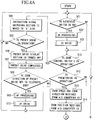
- Step 401 determine whether the auto focus switch 28 is turned on (Step 402).
- Step 411 When the auto focus switch 28 is not ON, proceed to Step 411.
- Step 402 When the auto focus switch 28 is ON, proceed to Step 402 and perform AF processing.
- the AF processing based on an image signal outputted from the camera 29 connected to the lens apparatus, generates a reference signal for image signal processing by detecting a horizontal synchronized signal and a vertical synchronized signal by the synchronized signal detection section 30. Further, the auto focus processing section 31, using the reference signal for image signal processing, generates a motor control signal so as to maximize the sharpness evaluation value by extracting a sharpness evaluation value from the image signal outputted from the camera 29. And, proceed to Step 403 and perform the AF drive.
- the auto focus control section 32 drives the motor 33 by using the motor control signal from the auto focus processing section 31. As a result, the sharpness evaluation value becomes maximum. In other words, the focus lens optical system 34 is driven so as to be in-focus (focusing). When focusing adjustment is completed, the AF drive is finished. Then, proceed to Step 411. In Step 411, determine whether the zoom control switch 1 is in operation or not. When the zoom control switch 1 is in operation, in order to control the zoom lens optical system 7 by the zoom control switch 1, switch the instruction signal switching section 10 to the A side (Step 404).
- Step 405 determine whether the preset drive is in operation or not.
- Step 405 determines whether the preset drive is not in operation.
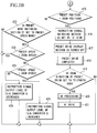
- Step 405 When the preset drive is in operation in Step 405, turn off the preset drive display section 19 (Step 406), and finish (stop) the preset drive (Step 407). Accordingly, in this case, it can be said that the preset drive is suspended partway. And, successively, determine whether the zoom direction of the preset drive is in the TELE direction or not (Step 408). When the zoom direction is in the TELE direction, perform the AF processing (Step 409). And, when focusing is achieved at the in-focus after AF driving, finish the AF drive (Step 410). An explanation on AF portion is omitted, as described before. And, return to the step to determine whether the auto focus switch is ON (Step 401). When the zoom direction is in the WIDE direction, also return to the step to determine whether the auto focus switch is ON (Step 401).
- Step 411 determine whether the preset drive is in operation (Step 412). When the preset drive is not in operation, then proceed to Step 427.
- Step 412 when the preset drive is determine to be in operation, obtain the speed of the zoom lens optical system 7 from the A/D converter 15 (Step 413), and further obtain the position of the zoom lens optical system 7 from the A/D converter 18 (Step 414).
- Step 415 check whether the zoom position obtained in Step 414 and a preset position stored in the storage section 6a in advance are equal (Step 415).
- Step 416 switch the instruction signal switching section 10 to the A side
- Step 417 turn off the preset drive display section 19
- Step 418 finish the preset drive
- Step 419 determines whether the zoom direction of the preset drive is in the TELE direction (Step 419).
- Step 420 perform the AF processing
- Step 431 finish the AF drive
- Step 415 when the zoom position and the preset position are not equal, using the preset mode switching section 21, determine which mode is selected between the maximum speed mode and the preset speed mode (Step 422).
- the preset speed mode refers to the mode in which the drive speed is set to the preset speed stored in the storage section 6a during preset driving
- the maximum speed mode refers to the mode in which the driving speed is set to the maximum speed attainable for the lens during preset driving.
- Step 423 determine whether the speed obtained in Step 413 and the preset speed stored in the storage section 6a in advance are equal or not (for example, whether the zoom speed is within a predetermined and allowed range with respect to the preset speed or not) (Step 423).
- Step 424 determine whether the preset speed is faster than the zoom speed or not.
- the preset speed increases the instruction signal output to the D/A converter 8 (Step 426).
- the preset speed is slower than the zoom speed, reduce the instruction signal output to the D/A converter 8 (Step 425).
- the preset speed mode is not selected, and when the zoom speed and the preset speed are equal, leave as they are and proceed to the next Step 427.
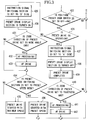
- Step 427 determine whether the position preset zoom switch 20 is switched from OFF to ON or not.
- Step 427 determines whether the position preset zoom switch 20 is switched from OFF to ON or not.
- Step 428 determines whether the preset drive is in operation or not.
- Step 428 switch the instruction signal switching section 10 to the B side (Step 429), and turn on the preset drive display section 19 (Step 430). And, determine whether the zoom direction of the preset drive is in the WIDE direction or not (Step 431).
- Step 434 by using the preset mode switching section 21, determine whether the preset speed mode is selected or not. When the preset speed mode is not selected (maximum speed mode), start the preset drive with the maximum speed which can be driven. Also, when the preset speed mode is selected, start the preset drive with the preset speed (Step 436).
- Step 415 when the zoom lens optical system 7 reaches to the preset position (Step 415), switch the instruction signal switching section 10 to the A side (step 416), turn off the preset drive display section 19 (Step 417), and finish the preset drive (Step 418).
- Step 419 When the zoom direction is in the TELE direction (Step 419), perform the AF processing (Step 420). And, when focusing is achieved at the in-focus after AF driving, finish the AF drive (Step 421).
- An explanation on the drive of AF portion is omitted, as described before.
- Step 428 when the preset drive is in operation in Step 428, switch the instruction signal switching section 10 to the A side (Step 437), turn off the preset drive display section 19 (Step 438), and finish the preset drive (Step 439).
- Step 440 determine whether the zoom direction of the preset drive is in the TELE direction.
- Step 441 When the zoom direction is in the TELE direction, perform the AF processing (Step 441). And, when focusing is achieved at the in-focus after zoom driving, finish the AF drive (Step 442).
- An explanation on the drive of AF portion is omitted, as described before. And, return to the step to determine whether the auto focus switch 28 is ON or not (Step 401)
- AF is able to offer precise preset image-taking of two arbitrarily different points just by performing focusing adjustment (focusing) without focusing adjustment by the user. Therefore, during the time of image-taking by using television cameras or video cameras, it is possible to broaden a range of image-taking methods, and to realize more significant preset functions further.
- the AF processing and AF drive are switched depending on the zoom direction of zoom preset drive, but, before the start of preset drive, they may be performed indiscriminately after reaching to a position stored in a position preset position memory.
- only preset processing may be performed immediately after preset driving, and, after reaching to the position stored in the position preset position memory, the AF drive may be performed. Or it may be performed in the midst of an active drive to the position stored in the position preset position memory.
- the AF processing is performed in the midst of an active drive to the position stored in the position preset position memory, and the AF drive may be performed after the completion of the preset drive.
- Embodiment 2 of the present invention by using a combined structure of the above-described preset drive and auto focus (AF) of the present invention, the auto focus is performed during "speed preset zoom control".
- FIG. 1 shows a block diagram of a lens apparatus (optical apparatus) according to the present embodiment. An explanation on each structural element is omitted, as explained in Embodiment 1.
- preset drive the drive to perform the auto focus during "speed preset zoom control" (hereinafter, referred to simply as preset drive) according to the present embodiment will be explained.
- This control during the preset drive is performed as follows. That is, an instruction signal outputted from CPU 6 is inputted into a motor 12 via a D/A converter 8, an instruction signal calculation section 9, a B side of a instruction signal switching section 10, and an electric power amplifier 11, and then the zoom lens optical system 7 is driven with a maximum speed or a preset speed set in advance. After this, by performing the AF processing by a synchronized signal detection section 30 and by inputting a control signal into a motor 33 via an auto focus processing section 31 and an auto focus control section 32, a focus lens optical system 34 is driven and when focusing is achieved at the in-focus is completed.
- Step 501 determines whether an auto focus switch 28 is ON or not (Step 501). When the auto focus switch 28 is not ON, proceed to Step 511. When the auto focus switch 28 is ON, proceed to Step 502 and perform the AF processing. And, when focusing is achieved at the in-focus after AF driving, finish the AF drive (Step 503). An explanation on the drive of AF portion is omitted, as described before.
- Step 511 determine whether the zoom control switch 1 is in operation or not.
- the zoom control switch 1 in order to perform the control of the zoom lens optical system 7 from the zoom control switch 1, switch the instruction signal switching section 10 to the A side (Step 504).
- Step 505 determine whether the preset drive is in operation or not.
- Step 505 determines whether the preset drive is not in operation.
- Step 505 When the preset drive is in operation in Step 505, turn off a preset drive display section 19 (Step 506), and finish (stop) the preset drive (Step 507). Therefore, in this case, it is to be said that the preset drive is suspended partway. And, successively, determine whether the zoom direction of the preset drive is in the TELE direction (Step 508). When the zoom direction is in the TELE direction, perform the AF processing (Step 509). And, when focusing is achieved at the in-focus after AF driving, finish the AF drive (Step 510). An explanation on the drive of AF portion is omitted, as described before. And, return to the step to determine whether the auto focus switch is ON or not (Step 501). When the zoom direction is in the WIDE direction, also return to the step to determine whether the auto focus switch is ON or not (Step 501).
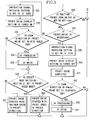
- Step 511 determine whether the preset drive is in operation or not (Step 512). When the preset drive is not in operation, proceed to Step 529.
- Step 512 When the preset drive is determine to be in operation in Step 512, obtain the speed and direction information of the zoom lens optical system 7 from the A/D converter 15 (Step 513), and further obtain the position information of the zoom lens optical system 7 from the A/D converter 18 (Step 514). Next, determine whether the zoom position obtained in Step 514 has reached to the edge position of the movable range of the lens apparatus or not (Step 515). When the position has reached to the end position of the movable range, switch the instruction signal switching section 10 to the A side (Step 516), turn off the preset drive display section 19 (Step 517), and finish the preset drive (Step 518).
- Step 519 determine whether the zoom direction of the preset drive is in the TELE direction or not.
- Step 520 perform the AF processing
- Step 521 finish the AF drive
- An explanation on the drive of AF portion is omitted, as described before.
- Step 523 determines whether the zoom position obtained in Step 513 and the preset speed stored in the memory 6a in advance by using the flow chart shown in FIGS. 4A and 4B described above are equal or not (for example, whether the zoom speed is in a predetermined and allowable range with respect to the preset speed) (Step 523). Conversely, when the preset speed mode is not selected (maximum speed mode), go to Step 529.
- Step 523 when the zoom speed and the preset speed are not equal, determine whether the preset speed is faster than the zoom speed or not (Step 524). When the preset speed is faster than the zoom speed, increase the instruction signal output into the D/A converter 8 (Step 526). Also, when the preset speed is slower than the zoom speed, reduce the instruction signal output into the D/A converter 8 (Step 525).
- Step 529 when the AF drive is finished, and when the zoom direction is in the WIDE direction in Step 519, then leave as they are, and go to Step 529.
- Step 529 determine whether the speed preset zoom switch 22 is switched from OFF to ON or not.
- Step 529 determines whether the speed preset zoom switch 22 is switched from OFF to ON or not.
- Step 530 determines whether the preset drive is in operation or not.
- Step 531 switch the instruction signal switching section 10 to the B side (Step 531), and turn on the preset drive display section 19 (Step 532).
- Step 533 determines whether the zoom direction of the preset drive is in the WIDE direction or not (Step 533).
- Step 534 perform the AF processing
- Step 535 finish the AF drive
- Step 536 by using the preset mode switching section 21, determine whether the preset speed mode is selected or not.
- the preset speed mode is not selected (maximum speed mode)
- start the preset drive with the maximum drivable speed toward the preset direction (Step 537).
- start the preset drive with the preset speed toward the preset direction (Step 538).
- Step 515 switch the instruction signal switching section 10 to the A side (Step 516), turn off the preset drive display section 19 (Step 517), finish the preset drive (Step 518), and when the zoom direction is in the TELE direction (Step 519), perform the AF processing (Step 520). And, when focusing is achieved at the in-focus after AF driving, finish the AF drive (Step 521). An explanation on the drive of AF portion is omitted, as described before.
- Step 530 when the preset drive is determined to be in operation in Step 530, switch the instruction signal switching section 10 to the A side (Step 539), turn off the preset drive display section 19 (Step 540), and finish the preset drive (Step 541).
- Step 542 determine whether the zoom direction of the preset drive is in the TELE direction or not (Step 542).
- Step 543 When the zoom direction is in the TELE direction, perform the AF processing (Step 543).
- Step 544 finish the AF drive (Step 544).
- An explanation on the drive of AF portion is omitted, as described before. And, return to the step to determine whether the auto focus switch 28 is ON or not (Step 501).
- AF is able to provide precise preset image-taking for two arbitrarily different points just by performing focusing adjustment (focusing) without focusing adjustment performed by the user. Therefore, during the time of image-taking by using television cameras or video cameras, it is possible to broaden a range of image-taking methods and to realize more significant preset functions further.
- the AF processing and AF drive are switched depending on the zoom direction of zoom preset drive, but, they may be performed indiscriminately immediately after the start of preset drive, or after reaching to the edge of the zoom movable range.
- only the AF processing may be performed immediately after the start of preset drive, and, the AF drive may be performed after reaching to the edge of the zoom movable range, or in the midst of the active drive toward the edge of the zoom movable range.
- the AF processing may be performed in the midst of the active drive to the edge of the zoom movable range and the AF drive may be performed after the completion of the preset drive.
Landscapes
- Engineering & Computer Science (AREA)
- Multimedia (AREA)
- Signal Processing (AREA)
- Lens Barrels (AREA)
- Studio Devices (AREA)
- Automatic Focus Adjustment (AREA)
Applications Claiming Priority (2)
| Application Number | Priority Date | Filing Date | Title |
|---|---|---|---|
| JP2003394189 | 2003-11-25 | ||
| JP2003394189A JP4478438B2 (ja) | 2003-11-25 | 2003-11-25 | 光学装置およびカメラシステム |
Publications (3)
| Publication Number | Publication Date |
|---|---|
| EP1536634A2 EP1536634A2 (en) | 2005-06-01 |
| EP1536634A3 EP1536634A3 (en) | 2009-12-30 |
| EP1536634B1 true EP1536634B1 (en) | 2017-06-21 |
Family
ID=34463778
Family Applications (1)
| Application Number | Title | Priority Date | Filing Date |
|---|---|---|---|
| EP04257301.4A Expired - Lifetime EP1536634B1 (en) | 2003-11-25 | 2004-11-24 | Optical apparatus and camera system |
Country Status (3)
| Country | Link |
|---|---|
| US (1) | US7511758B2 (enExample) |
| EP (1) | EP1536634B1 (enExample) |
| JP (1) | JP4478438B2 (enExample) |
Families Citing this family (1)
| Publication number | Priority date | Publication date | Assignee | Title |
|---|---|---|---|---|
| JP2006197320A (ja) * | 2005-01-14 | 2006-07-27 | Elmo Co Ltd | 資料提示装置 |
Family Cites Families (14)
| Publication number | Priority date | Publication date | Assignee | Title |
|---|---|---|---|---|
| JPH01293771A (ja) * | 1988-05-20 | 1989-11-27 | Victor Co Of Japan Ltd | オートフォーカス方式 |
| JP2728943B2 (ja) * | 1989-07-08 | 1998-03-18 | キヤノン株式会社 | レンズ制御装置 |
| JP3271150B2 (ja) * | 1992-03-30 | 2002-04-02 | ソニー株式会社 | レンズ位置調整装置及び方法 |
| KR0147572B1 (ko) * | 1992-10-09 | 1998-09-15 | 김광호 | 자동 줌잉을 위한 피사체 추적방법 및 그 장치 |
| KR100197609B1 (ko) * | 1996-07-27 | 1999-06-15 | 윤종용 | 비데오카메라의 줌(zoom)기능 수행방법 및 그 장치 |
| JP3420542B2 (ja) | 1999-10-28 | 2003-06-23 | キヤノン株式会社 | 光学装置、光学装置駆動ユニットおよびカメラシステム |
| US7079182B1 (en) | 1999-10-28 | 2006-07-18 | Canon Kabushiki Kaisha | Optical apparatus, optical apparatus driving unit and camera system |
| JP2001258017A (ja) * | 2000-03-14 | 2001-09-21 | Canon Inc | 監視カメラシステム及びその制御方法 |
| JP3450795B2 (ja) * | 2000-04-05 | 2003-09-29 | キヤノン株式会社 | 光学装置、光学装置駆動ユニット、情報書込装置、プリセット情報設定システムおよびカメラシステム |
| JP2002094865A (ja) * | 2000-09-12 | 2002-03-29 | Matsushita Electric Ind Co Ltd | 画像認証装置 |
| JP4986346B2 (ja) * | 2001-08-09 | 2012-07-25 | パナソニック株式会社 | 撮像装置のレンズ駆動方法及び撮像装置並びにカメラシステム |
| JP4669170B2 (ja) * | 2001-08-10 | 2011-04-13 | キヤノン株式会社 | ズームレンズ制御装置、ズームレンズ制御方法、及びプログラム |
| JP3673773B2 (ja) * | 2002-06-21 | 2005-07-20 | キヤノン株式会社 | 光学装置、光学装置駆動ユニットおよびカメラシステム |
| JP3673774B2 (ja) * | 2002-06-21 | 2005-07-20 | キヤノン株式会社 | 光学装置、光学装置駆動ユニットおよびカメラシステム |
-
2003
- 2003-11-25 JP JP2003394189A patent/JP4478438B2/ja not_active Expired - Fee Related
-
2004
- 2004-11-22 US US10/996,215 patent/US7511758B2/en active Active
- 2004-11-24 EP EP04257301.4A patent/EP1536634B1/en not_active Expired - Lifetime
Also Published As
| Publication number | Publication date |
|---|---|
| EP1536634A2 (en) | 2005-06-01 |
| US20050110891A1 (en) | 2005-05-26 |
| JP4478438B2 (ja) | 2010-06-09 |
| EP1536634A3 (en) | 2009-12-30 |
| JP2005156849A (ja) | 2005-06-16 |
| US7511758B2 (en) | 2009-03-31 |
Similar Documents
| Publication | Publication Date | Title |
|---|---|---|
| CN1402076B (zh) | 变焦透镜控制装置 | |
| CN109729262B (zh) | 透镜控制设备和方法以及包括透镜控制设备的摄像设备 | |
| JPH0654366B2 (ja) | ズ−ミング方法およびズ−ミング装置 | |
| JP2963006B2 (ja) | カメラ装置 | |
| JP4986346B2 (ja) | 撮像装置のレンズ駆動方法及び撮像装置並びにカメラシステム | |
| JP2003051980A (ja) | オートフォーカス装置及び撮像装置並びにカメラシステム | |
| US5742435A (en) | Video-camera imaging-system zoom lens barrel | |
| EP1536634B1 (en) | Optical apparatus and camera system | |
| EP1369727B1 (en) | Optical driving unit, optical apparatus and camera system | |
| JP2001051183A (ja) | レンズ装置 | |
| JP2752291B2 (ja) | フォーカス制御装置 | |
| JP4981343B2 (ja) | 雲台システム | |
| JP3915104B2 (ja) | レンズの制御方法 | |
| JP2006195060A (ja) | オートフォーカス装置 | |
| JP3609730B2 (ja) | レンズ装置 | |
| JPH05191701A (ja) | 撮影装置あるいはレンズ位置制御装置 | |
| JP5574729B2 (ja) | レンズ制御装置、その制御方法及びプログラム | |
| KR100860793B1 (ko) | 매뉴얼 포커스를 이용한 포커스 가변형 카메라 시스템 | |
| JPH0943483A (ja) | レンズ制御装置及びそのレンズ位置調整方法 | |
| JPH0662300A (ja) | レンズ制御装置 | |
| JP3673773B2 (ja) | 光学装置、光学装置駆動ユニットおよびカメラシステム | |
| JP3213477B2 (ja) | オートフォーカスビデオカメラ | |
| JPH0783445B2 (ja) | 撮像装置 | |
| JP3673774B2 (ja) | 光学装置、光学装置駆動ユニットおよびカメラシステム | |
| KR100515205B1 (ko) | 줌카메라의 주밍 속도 제어 방법 |
Legal Events
| Date | Code | Title | Description |
|---|---|---|---|
| PUAI | Public reference made under article 153(3) epc to a published international application that has entered the european phase |
Free format text: ORIGINAL CODE: 0009012 |
|
| AK | Designated contracting states |
Kind code of ref document: A2 Designated state(s): AT BE BG CH CY CZ DE DK EE ES FI FR GB GR HU IE IS IT LI LU MC NL PL PT RO SE SI SK TR |
|
| AX | Request for extension of the european patent |
Extension state: AL HR LT LV MK YU |
|
| PUAL | Search report despatched |
Free format text: ORIGINAL CODE: 0009013 |
|
| AK | Designated contracting states |
Kind code of ref document: A3 Designated state(s): AT BE BG CH CY CZ DE DK EE ES FI FR GB GR HU IE IS IT LI LU MC NL PL PT RO SE SI SK TR |
|
| AX | Request for extension of the european patent |
Extension state: AL HR LT LV MK YU |
|
| 17P | Request for examination filed |
Effective date: 20100630 |
|
| AKX | Designation fees paid |
Designated state(s): DE FR GB |
|
| 17Q | First examination report despatched |
Effective date: 20100824 |
|
| GRAP | Despatch of communication of intention to grant a patent |
Free format text: ORIGINAL CODE: EPIDOSNIGR1 |
|
| INTG | Intention to grant announced |
Effective date: 20170116 |
|
| GRAS | Grant fee paid |
Free format text: ORIGINAL CODE: EPIDOSNIGR3 |
|
| GRAA | (expected) grant |
Free format text: ORIGINAL CODE: 0009210 |
|
| AK | Designated contracting states |
Kind code of ref document: B1 Designated state(s): DE FR GB |
|
| REG | Reference to a national code |
Ref country code: GB Ref legal event code: FG4D |
|
| REG | Reference to a national code |
Ref country code: DE Ref legal event code: R096 Ref document number: 602004051422 Country of ref document: DE |
|
| REG | Reference to a national code |
Ref country code: DE Ref legal event code: R097 Ref document number: 602004051422 Country of ref document: DE |
|
| PLBE | No opposition filed within time limit |
Free format text: ORIGINAL CODE: 0009261 |
|
| STAA | Information on the status of an ep patent application or granted ep patent |
Free format text: STATUS: NO OPPOSITION FILED WITHIN TIME LIMIT |
|
| 26N | No opposition filed |
Effective date: 20180322 |
|
| GBPC | Gb: european patent ceased through non-payment of renewal fee |
Effective date: 20171124 |
|
| REG | Reference to a national code |
Ref country code: FR Ref legal event code: ST Effective date: 20180731 |
|
| PG25 | Lapsed in a contracting state [announced via postgrant information from national office to epo] |
Ref country code: FR Free format text: LAPSE BECAUSE OF NON-PAYMENT OF DUE FEES Effective date: 20171130 |
|
| PG25 | Lapsed in a contracting state [announced via postgrant information from national office to epo] |
Ref country code: GB Free format text: LAPSE BECAUSE OF NON-PAYMENT OF DUE FEES Effective date: 20171124 |
|
| PGFP | Annual fee paid to national office [announced via postgrant information from national office to epo] |
Ref country code: DE Payment date: 20200130 Year of fee payment: 16 |
|
| REG | Reference to a national code |
Ref country code: DE Ref legal event code: R119 Ref document number: 602004051422 Country of ref document: DE |
|
| PG25 | Lapsed in a contracting state [announced via postgrant information from national office to epo] |
Ref country code: DE Free format text: LAPSE BECAUSE OF NON-PAYMENT OF DUE FEES Effective date: 20210601 |