EP1535867B1 - Dispositif et procédé d'avance pour des balles ou des bottes de tabac - Google Patents
Dispositif et procédé d'avance pour des balles ou des bottes de tabac Download PDFInfo
- Publication number
- EP1535867B1 EP1535867B1 EP04019870A EP04019870A EP1535867B1 EP 1535867 B1 EP1535867 B1 EP 1535867B1 EP 04019870 A EP04019870 A EP 04019870A EP 04019870 A EP04019870 A EP 04019870A EP 1535867 B1 EP1535867 B1 EP 1535867B1
- Authority
- EP
- European Patent Office
- Prior art keywords
- tobacco
- pusher
- slide
- guide
- conveying direction
- Prior art date
- Legal status (The legal status is an assumption and is not a legal conclusion. Google has not performed a legal analysis and makes no representation as to the accuracy of the status listed.)
- Expired - Lifetime
Links
- 241000208125 Nicotiana Species 0.000 title claims abstract description 91
- 235000002637 Nicotiana tabacum Nutrition 0.000 title claims abstract description 91
- 238000000034 method Methods 0.000 title claims abstract description 12
- 230000001174 ascending effect Effects 0.000 claims 1
- 230000032258 transport Effects 0.000 description 39
- 230000001747 exhibiting effect Effects 0.000 description 5
- 238000011144 upstream manufacturing Methods 0.000 description 2
- 230000001419 dependent effect Effects 0.000 description 1
- 238000012986 modification Methods 0.000 description 1
- 230000004048 modification Effects 0.000 description 1
Images

Classifications
-
- B—PERFORMING OPERATIONS; TRANSPORTING
- B65—CONVEYING; PACKING; STORING; HANDLING THIN OR FILAMENTARY MATERIAL
- B65G—TRANSPORT OR STORAGE DEVICES, e.g. CONVEYORS FOR LOADING OR TIPPING, SHOP CONVEYOR SYSTEMS OR PNEUMATIC TUBE CONVEYORS
- B65G47/00—Article or material-handling devices associated with conveyors; Methods employing such devices
- B65G47/74—Feeding, transfer, or discharging devices of particular kinds or types
- B65G47/82—Rotary or reciprocating members for direct action on articles or materials, e.g. pushers, rakes, shovels
-
- B—PERFORMING OPERATIONS; TRANSPORTING
- B65—CONVEYING; PACKING; STORING; HANDLING THIN OR FILAMENTARY MATERIAL
- B65G—TRANSPORT OR STORAGE DEVICES, e.g. CONVEYORS FOR LOADING OR TIPPING, SHOP CONVEYOR SYSTEMS OR PNEUMATIC TUBE CONVEYORS
- B65G25/00—Conveyors comprising a cyclically-moving, e.g. reciprocating, carrier or impeller which is disengaged from the load during the return part of its movement
- B65G25/04—Conveyors comprising a cyclically-moving, e.g. reciprocating, carrier or impeller which is disengaged from the load during the return part of its movement the carrier or impeller having identical forward and return paths of movement, e.g. reciprocating conveyors
- B65G25/08—Conveyors comprising a cyclically-moving, e.g. reciprocating, carrier or impeller which is disengaged from the load during the return part of its movement the carrier or impeller having identical forward and return paths of movement, e.g. reciprocating conveyors having impellers, e.g. pushers
- B65G25/10—Conveyors comprising a cyclically-moving, e.g. reciprocating, carrier or impeller which is disengaged from the load during the return part of its movement the carrier or impeller having identical forward and return paths of movement, e.g. reciprocating conveyors having impellers, e.g. pushers with impeller pivotally mounted on a reciprocating bar
Definitions
- the present invention relates to a device according to the preamble of claim 1 or 2 and a method according to the preamble of claim 11 or 12 for transporting several tobacco leaf layers exhibiting tobacco bales and for transporting tobacco containers, such as boxes, boxes, containers and other containers of a upstream to a downstream device, for example, from a tobacco bale receiving station to a stripping station for stripping a plurality of tobacco leaf layers exhibiting tobacco bales or to a Slicestation for slicing several tobacco leaf layers exhibiting tobacco bales.
- tobacco is regularly delivered in tobacco bales consisting of dry and compressed tobacco leaves.
- these bales of tobacco preferably in their individual tobacco leaves, must be separated.
- the individual tobacco leaves must be separated from each other or the tobacco bales are stripped. This is preferably done parallel to the levels of the tobacco leaf layers in the tobacco bales. In this way it is possible to uniformly feed tobacco with the help of individual tobacco leaves a release device for the tobacco. In addition, it is possible to uniformly feed the tobacco bales substantially across the levels of tobacco leaves to Slicen and the release device with geslicetem tobacco.
- a plurality of tobacco packs such as cartons, boxes, containers, trays and other containers, are also transported from a device to a downstream device.
- EP 03017071.6 (Application number) is a device for transporting several tobacco leaf layers containing tobacco bales along a ground transport path from an upstream tobacco bale receiving station to a stripping station with a first slider and a second slider for pushing a tobacco bale relative to the ground and one between the two slides to a transfer position switched fuser known.
- Both slides each comprise a pair of sliding plates which can be pivoted in and out and are each guided via a slide in a common guide, which comprises two guide rails and extends in the transport direction over the transfer position.
- the first slider pushes the tobacco bale along the transport path into the transfer position up to the fixing unit, which temporarily fixes the tobacco bale in the transfer position.
- the second slider takes over the tobacco bales and pushes them along the transport route to the stripping station.
- a tobacco bale is transported over a first section of the transport path by a first slider and a second section of the transport path of a second slide sections, so that always involved in the transport of a tobacco bale along its transport path from a task end to a discharge end two slides ,
- Object of the present invention is compared to the known device or to the known method an alternative device and an alternative method for transporting several tobacco leaf layers exhibiting tobacco bales and for transporting tobacco containers indicate.
- the proposed devices and the proposed methods enable a continuous transport of successive tobacco bales and successive tobacco packages along the transport path.
- a transfer or takeover of the tobacco bale along the transport path from the first slide to the second slide can thus be omitted.
- the other slide can still guarantee transport.
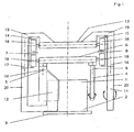
- the sliding plates 4, 5 are spaced from each other transversely to the transport direction attached to a first carriage 6.
- the first carriage 6 is reciprocated in a transport direction formed by a pair of rails 7, 8 first guide in the transport direction and forth.
- the sliding plates 4, 5 are received in the first carriage 6 in each case about the pivot axis 9, 10 and swing out.
- the device further comprises a second slide formed by two slide plates 11, 12.
- the slide plates 11, 12 are spaced from each other transversely to the transport direction attached to a second carriage 13.
- the second carriage 13 is guided back and forth in the transport direction in a direction formed by a pair of rails 14, 15 second guide.
- the sliding plates 11, 12 are received in the second carriage 13 respectively about the pivot axis 16, 17 and swung out.
- the first guide formed by the pair of rails 7, 8 and the second guide formed by the pair of rails 14, 15 are arranged transversely to the transport direction at a distance from each other above the bottom 3 and parallel adjacent in the transport direction.
- the carriages 6, 13 are movably received via rollers 18 in the pairs of rails 7, 8, 14, 15.
- the second carriage 13 forms two of the first carriage 6 laterally overlapping and angled in the bottom direction arms 19, which carry the provided with angled arms 20 slide plates 11, 12.
- the carriage 6, 13 are provided by means not shown motors in as well as counter to the transport direction movable.
- the sliding plates 4, 5, 11, 12 are by means of Not shown adjustment provided pivotably about their respective pivot axes.
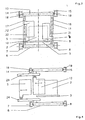
- the distance of the pivot axes 9, 10 of the first slider 4, 5 is transverse to the transport direction less than the distance of the pivot axes 16, 17 of the second slider 11, 12, so that the second carriage 13 can be moved past the first carriage 6, when the Sliders 11 and 12 are pivoted in the rest position.
- Fig. 1 the sliding plates 5 and 12 are shown in the left half in the pivoted working position and the sliding plates 4 and 11 in the right half in the rest position. During transport, the sliding plates 4, 5 and / or the sliding plates 11 and 12, however, pivoted in pairs, as shown in Fig. 2.
- a first tobacco bale 2 is abandoned at the task end A and the first slide 4, 5 moved to task end A, which engages behind the first tobacco bale 2 after pivoting the sliding plates 4, 5 and relative to the bottom 3 along the transport path A, B up the discharge end B pushes.
- the second slide 11, 12 is moved past the first slider 4, 5 pushing the first tobacco bale 2 past the feed end A against the transport direction.
- the second slider 11, 12 engages by means of pivoting the slide plates 11, 12 the second tobacco bales and pushes it relative to the bottom 3 along the transport path A, B to the discharge end B, while the first slider 4, 5 against the transport direction to the task end A, on which the second tobacco balls 2 sliding second slider 11, 12 over, with back in the rest position pivoted sliding plates 4, 5, is moved back.
- the second slide 11, 12 can be moved back past the first slide 4, 5 in order to transport another tobacco bale.
- a first guide 7, 8 is arranged below the base 3 and a second guide 14, 15 above the base 3.
- the pivot axes 9, 10 of the first slider 4, 5 and the pivot axes 16, 17 of the second slider 11, 12 are arranged in alignment in the transport direction, so that on a pivot axis 9 with pivot axis 16 and the other pivot axis 10 is aligned with pivot axis 17.
- Each sliding plate 4, 5, 11, 12 has a recess 21, 22.
- the recesses 21 and 22 correspond to the cross-sectional area of the respective other slide 4, 5, 11, 12 in its rest position, to ensure a reliable and collision-free passage.
- the recesses 21 of the sliding plates 4, 5 and the recesses 22 of the sliding plates 11, 12 are pairwise mirror-symmetrical.
- the sliding plates 4 and 12 are shown in Figureschwenktem and the sliding plates 5 and 11 in the rest position, which differs from the same working position in pairs.
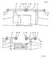
- Fig. 4 shows a further embodiment of slides 5, 12 in which the slides 4, 11 are not shown, since they are formed corresponding point-symmetrical.
- the slides 5, 12 are translationally on and extendable attached to the respective carriage 6, 13.
- For translational retraction and extension adjustment 23, 24 are provided.
- Fig. 5 shows a further embodiment of sliders 4, 12 which are pivotally provided about the pivot axes 9 and 17.
- the first slide comprises a single slide plate 4 and the second slide a single slide plate 12.
- the first guide 7, 8 and the second guide 14, 15 are arranged in a common plane above the bottom 3, which advantageously dirt in the Let guides avoid.
- FIG. 6 shows a further embodiment of slides 4, 12, in which again the first guide 7, 8 and the second guide 14, 15 are arranged in a common plane above the floor 3.
- the sliding plates 4, 12 are formed tooth-like interlocking to a largely closed contact surface for the tobacco bale to build.
- a horizontal pivoting possibility of the sliding plates 4 and 12 is provided here around the horizontally arranged pivot axes 25 and 26, if a vertical pivoting is to be dispensed with.
Landscapes
- Engineering & Computer Science (AREA)
- Mechanical Engineering (AREA)
- Manufacture Of Tobacco Products (AREA)
- Wrapping Of Specific Fragile Articles (AREA)
- Preliminary Treatment Of Fibers (AREA)
- Manufacturing Of Cigar And Cigarette Tobacco (AREA)
- Specific Conveyance Elements (AREA)
Claims (14)
- Dispositif pour le transport de balles de tabac (2) présentant plusieurs bottes de tabac (1), comportant un fond (3) pour la réception des balles de tabac (2), une première coulisse qui est fixée sur un premier chariot (6), le premier chariot (6) étant guidé dans un premier guidage dans le sens de transport de façon à pouvoir se déplacer dans les deux sens, et une deuxième coulisse qui est fixée sur un deuxième chariot (13), le deuxième chariot (13) étant guidé dans un deuxième guidage dans le sens de transport de façon à pouvoir se déplacer dans les deux sens, caractérisé en ce que le premier guidage pour le premier chariot (6) est constitué d'une paire de rails (7, 8) et le deuxième guidage pour le deuxième chariot (13), d'une paire de rails (14, 15), et en ce que les paires de rails (7, 8 ; 14, 15) sont disposées à distance l'une de l'autre transversalement au sens de transport et en ce qu'elles sont disposées en étant adjacentes, parallèles en continu dans le sens de transport, et en ce que des plaques coulissantes (4, 5) de la première coulisse et des plaques coulissantes (11, 12) de la deuxième coulisse sont respectivement mobiles autour d'un axe de pivotement (9, 10 et 16, 17) perpendiculaire au sens de transport des chariots (6, 13).
- Dispositif pour le transport de balles de tabac (2) présentant plusieurs bottes de tabac (1), comportant un fond (3) pour la réception des balles de tabac (2), une première coulisse qui est fixée sur un premier chariot (6), le premier chariot (6) étant guidé dans un premier guidage dans le sens de transport de façon à pouvoir se déplacer dans les deux sens, et une deuxième coulisse qui est fixée sur un deuxième chariot (13), le deuxième chariot (13) étant guidé dans un deuxième guidage dans le sens de transport de façon à pouvoir se déplacer dans les deux sens, caractérisé en ce que le premier guidage pour le premier chariot (6) est constitué d'une paire de rails (7, 8) et le deuxième guidage pour le deuxième chariot (13), d'une paire de rails (14, 15) et en ce que les paires de rails (7, 8 ; 14, 15) sont disposées à distance l'une de l'autre transversalement au sens de transport et en ce qu'elles sont disposées en étant adjacentes, parallèles en continu dans le sens de transport, et en ce que des plaques coulissantes (4, 5) de la première coulisse et des plaques coulissantes (11, 12) de la deuxième coulisse sont respectivement fixées sur le chariot respectif (6, 13) de manière à pouvoir entrer et sortir de façon translatoire.
- Dispositif selon la revendication 1 ou 2, caractérisé en ce qu'au moins une plaque coulissante (4, 5, 11, 12) est réalisée de façon à pouvoir se déplacer dans les deux sens d'une position de repos à une position de travail.
- Dispositif selon l'une des revendications 1 à 3, caractérisé en ce que le premier guidage et le deuxième guidage sont disposés sur ou sous le fond (3).
- Dispositif selon l'une des revendications 1 à 4, caractérisé en ce que le premier guidage (7, 8) et le deuxième guidage (14, 15) sont disposés dans un plan commun sur ou sous le fond (3).
- Dispositif selon l'une des revendications 1 à 3, caractérisé en ce que le premier guidage est disposé sur le fond (3) et le deuxième guidage sous le fond (3).
- Dispositif selon la revendication 1, caractérisé en ce que l'axe de pivotement (9, 10) de la première coulisse et l'axe de pivotement (16, 17) de la deuxième coulisse sont disposés selon un alignement dans le sens de transport et en ce que chaque plaque coulissante (4, 5, 11, 12) présente un évidement (21, 22) qui correspond, à peu près, de façon privilégiée à 100 à 250 %, de façon particulièrement privilégiée à 120 à 200 %, de la surface de la section transversale de l'autre plaque coulissante respective (4, 5, 11, 12) en position de repos.
- Dispositif selon la revendication 1 ou 7, caractérisé en ce que la distance entre les axes de pivotement (9, 10) des premières plaques coulissantes (4, 5) est plus petite transversalement au sens de transport que la distance entre les axes de pivotement (16, 17) des deuxièmes plaques coulissantes (11, 12).
- Dispositif selon l'une des revendications 1 à 8, caractérisé en ce que le fond (3) est réalisé par une bande transporteuse.
- Dispositif selon l'une des revendications 1 à 9, caractérisé en ce que le fond (3) est disposé en remontant dans le sens de transport, de façon privilégiée avec une pente de 1 à 20 degrés, de façon particulièrement privilégiée de 3 à 15 degrés.
- Procédé pour le transport de deux balles de tabac (2) successives présentant plusieurs bottes de tabac (1), le long d'un parcours de transport (A, B) avec une extrémité d'alimentation (A) et une extrémité de déchargement (B), dans lequel les balles de tabac (2) sont chargées l'une après l'autre à l'extrémité d'alimentation (A) du parcours de transport (A, B) sur un fond (3) s'étendant le long du parcours de transport (A, B) et sont transportées de l'extrémité d'alimentation (A) vers l'extrémité de déchargement (B) du parcours de transport (A, B), les balles de tabac (2) étant déplacées à l'aide d'une première coulisse qui est fixée sur un premier chariot (6), et d'une deuxième coulisse qui est fixée sur un deuxième chariot (13), et les chariots (6, 13) étant guidés dans des premier et deuxième guidages correspondants, caractérisé en ce qu'une première balle de tabac (2) est chargée à l'extrémité d'alimentation (A), en ce que des plaques coulissantes (4, 5) de la première coulisse sont déplacées vers l'extrémité d'alimentation (A), saisissent la première balle de tabac (2) par derrière et les font glisser par rapport au fond (3) le long du parcours de transport (A, B) jusqu'à l'extrémité de déchargement (B), en ce qu'une deuxième balle de tabac (2) est chargée à l'extrémité d'alimentation (A) et en ce que des plaques coulissantes (11, 12) de la deuxième coulisse sont déplacées vers l'extrémité d'alimentation (A), dans le sens inverse du sens de transport, en passant devant les première plaques coulissantes (4, 5) poussant la première balle de tabac (2), saisissent la deuxième balle de tabac (2) par derrière et les font glisser par rapport au fond (3) le long du parcours de transport (A, B) jusqu'à l'extrémité de déchargement (B), tandis que les plaques coulissantes (4, 5) de la première coulisse sont redéplacées vers l'extrémité d'alimentation (A) dans le sens inverse du sens de transport en passant devant les plaques coulissantes (11, 12), de la deuxième coulisse, poussant la deuxième balle de tabac (2), les chariots (6, 13) étant respectivement déplacés, de façon adjacente, parallèle en continu, le long d'une paire de rails (7, 8 et 14, 15) et les plaques coulissantes (4, 5 ; 11, 12) affectées aux chariots (6, 13) étant engagées et sorties en pivotant autour des axes de pivotement (9, 10 et 16, 17) verticaux pour la saisie par derrière des balles de tabac (2) et pour l'occupation d'une position de repos.
- Procédé pour le transport de deux balles de tabac (2) successives présentant plusieurs bottes de tabac (1), le long d'un parcours de transport (A, B) avec une extrémité d'alimentation (A) et une extrémité de déchargement (B), dans lequel les balles de tabac (2) sont chargées l'une après l'autre à l'extrémité d'alimentation (A) du parcours de transport (A, B) sur un fond (3) s'étendant le long du parcours de transport (A, B) et sont transportées de l'extrémité d'alimentation (A) vers l'extrémité de déchargement (B) du parcours de transport (A, B), les balles de tabac (2) étant déplacées à l'aide d'une première coulisse qui est fixée sur un premier chariot (6), et d'une deuxième coulisse qui est fixée sur un deuxième chariot (13), et les chariots (6, 13) étant guidés dans des premier et deuxième guidages correspondants, caractérisé en ce qu'une première balle de tabac (2) est chargée à l'extrémité d'alimentation (A), en ce que des plaques coulissantes (4, 5) de la première coulisse sont déplacées vers l'extrémité d'alimentation (A), saisissent la première balle de tabac (2) par derrière et les font glisser par rapport au fond (3) le long du parcours de transport (A, B) jusqu'à l'extrémité de déchargement (B), en ce qu'une deuxième balle de tabac (2) est chargée à l'extrémité d'alimentation (A) et en ce que des plaques coulissantes (11, 12) de la deuxième coulisse sont déplacées vers l'extrémité d'alimentation (A) dans le sens inverse du sens de transport en passant devant les première plaques coulissantes (4, 5) poussant la première balle de tabac (2), saisissent la deuxième balle de tabac (2) par derrière et les font glisser par rapport au fond (3) le long du parcours de transport (A, B) jusqu'à l'extrémité de déchargement (B), tandis que les plaques coulissantes (4, 5) de la première coulisse sont redéplacées vers l'extrémité d'alimentation (A) dans le sens inverse du sens de transport en passant devant les plaques coulissantes (11, 12), de la deuxième coulisse, poussant la deuxième balle de tabac (2), les chariots (6, 13) étant respectivement déplacés, de façon adjacente, parallèle en continu, le long d'une paire de rails (7, 8 et 14, 15) et les plaques coulissantes (4, 5 ; 11, 12) affectées aux chariots (6, 13) étant déplacées vers l'intérieur et vers l'extérieur de façon translatoire pour la saisie par derrière des balles de tabac (2) et pour l'occupation d'une position de repos.
- Procédé selon la revendication 11 ou 12, caractérisé en ce que les plaques coulissantes (4, 5, 11, 12) sont respectivement en position de repos pendant qu'elles sont redéplacées vers l'extrémité d'alimentation (A) dans le sens inverse de transport.
- Procédé selon l'une des revendications 11 à 13, caractérisé en ce que les chariots (6, 13) sont entraînés et déplacés isolément à l'aide de moteurs.
Applications Claiming Priority (2)
| Application Number | Priority Date | Filing Date | Title |
|---|---|---|---|
| DE10355391A DE10355391B4 (de) | 2003-11-25 | 2003-11-25 | Transportvorrichtung und -verfahren für Tabakballen und -gebinde |
| DE10355391 | 2003-11-25 |
Publications (2)
| Publication Number | Publication Date |
|---|---|
| EP1535867A1 EP1535867A1 (fr) | 2005-06-01 |
| EP1535867B1 true EP1535867B1 (fr) | 2007-08-08 |
Family
ID=34442307
Family Applications (1)
| Application Number | Title | Priority Date | Filing Date |
|---|---|---|---|
| EP04019870A Expired - Lifetime EP1535867B1 (fr) | 2003-11-25 | 2004-08-21 | Dispositif et procédé d'avance pour des balles ou des bottes de tabac |
Country Status (4)
| Country | Link |
|---|---|
| EP (1) | EP1535867B1 (fr) |
| CN (1) | CN1621328A (fr) |
| AT (1) | ATE369308T1 (fr) |
| DE (2) | DE10355391B4 (fr) |
Families Citing this family (4)
| Publication number | Priority date | Publication date | Assignee | Title |
|---|---|---|---|---|
| CN100460298C (zh) * | 2006-01-25 | 2009-02-11 | 云南昆船设计研究院 | 一种走行补货装置 |
| DE102011007233B4 (de) * | 2011-04-12 | 2019-11-07 | Winkler und Dünnebier Süßwarenmaschinen GmbH | Transportvorrichtung mit einer mehrere Transportabschnitte aufweisenden Transportstrecke für einen abschnittsweisen Transport durch Mitnehmer |
| ITBO20120517A1 (it) * | 2012-09-25 | 2014-03-26 | Corima Internat Machinery S R L | Macchina per aprire confezioni di coperchi |
| ITBO20120516A1 (it) * | 2012-09-25 | 2014-03-26 | Corima Internat Machinery S R L | Macchina per aprire confezioni di coperchi |
Family Cites Families (6)
| Publication number | Priority date | Publication date | Assignee | Title |
|---|---|---|---|---|
| DE8418005U1 (de) * | 1984-06-14 | 1984-10-04 | Wilh. Quester Maschinenfabrik GmbH, 5030 Hürth | Beschickungsvorrichtung |
| DE9306508U1 (de) * | 1993-04-30 | 1993-07-01 | Paper Converting Machine Gmbh, 6707 Schifferstadt | Vorrichtung zum Transport von Produkten |
| GB9318196D0 (en) * | 1993-09-02 | 1993-10-20 | British American Tobacco Co | Cutting tobacco blanes |
| DE10048255B4 (de) * | 2000-09-29 | 2004-03-18 | Federal-Mogul Wiesbaden Gmbh & Co. Kg | Transportvorrichtung |
| DE10214684A1 (de) * | 2002-03-28 | 2003-10-09 | Bielomatik Leuze & Co | Fördereinrichtung und Verfahren zur Überführung von Stapeln aus Papier oder dgl. auf einen Abtransportförderer |
| EP1502511A3 (fr) * | 2003-07-28 | 2005-04-13 | Hauni Maschinenbau AG | Delamination de balles de tabac |
-
2003
- 2003-11-25 DE DE10355391A patent/DE10355391B4/de not_active Expired - Fee Related
-
2004
- 2004-08-21 AT AT04019870T patent/ATE369308T1/de not_active IP Right Cessation
- 2004-08-21 EP EP04019870A patent/EP1535867B1/fr not_active Expired - Lifetime
- 2004-08-21 DE DE502004004558T patent/DE502004004558D1/de not_active Expired - Fee Related
- 2004-11-24 CN CN200410095392.0A patent/CN1621328A/zh active Pending
Non-Patent Citations (1)
| Title |
|---|
| None * |
Also Published As
| Publication number | Publication date |
|---|---|
| DE502004004558D1 (de) | 2007-09-20 |
| DE10355391B4 (de) | 2005-10-20 |
| ATE369308T1 (de) | 2007-08-15 |
| CN1621328A (zh) | 2005-06-01 |
| DE10355391A1 (de) | 2005-06-30 |
| EP1535867A1 (fr) | 2005-06-01 |
Similar Documents
| Publication | Publication Date | Title |
|---|---|---|
| DE1817869C3 (de) | Forderanordnung fur den Transport von Filterstaben, Zigaretten oder anderen stabformigen Artikeln der tabakverarbeiten den Industrie Ausscheidung aus 1815317 | |
| DE3232039A1 (de) | Vorrichtung zum befoerdern von sortiertem, gestapeltem gut | |
| DE2745298C2 (de) | Vorrichtung zum Fördern und Verteilen von Gegenständen | |
| DE69422661T2 (de) | Verfahren und Vorrichtung zum Einwickeln von Gegenständen | |
| DE2125991A1 (de) | Verfahren und Vorrichtung zum Transport gestapelter flacher Gegenstände in Aufeinanderfolge zu einem Auffangen | |
| DE4036214C2 (fr) | ||
| DE69718374T2 (de) | Verfahren und Vorrichtung zum geordneten Abführen von ungeordnet zugeführten Produkten | |
| WO2021037610A1 (fr) | Dispositif et procédé pour transporter et trier des colis | |
| EP3332930A1 (fr) | Dispositif d'alimentation, machine de revêtement ainsi que dispositif de stockage | |
| EP1574459B1 (fr) | Dispositif et procédé pour le transfert de produits parallélépipèdiques dans une certaine position | |
| DE69802760T2 (de) | Verfahren und Vorrichtung zum Zuführen von Zuschnitten zu einer Verwendungsmaschine | |
| EP1169249A1 (fr) | Procede et dispositif pour transporter des produits en vrac | |
| EP0558035B1 (fr) | Dispositif pour empiler des coupelles, notamment des coupelles de vaisselles | |
| DE2500786A1 (de) | Foerderanlage | |
| DE2603165A1 (de) | Foerderanlage mit foerderstiften fuer werkstuecke mit oeffnungen | |
| EP1535867B1 (fr) | Dispositif et procédé d'avance pour des balles ou des bottes de tabac | |
| EP1302419B1 (fr) | Procédé et dispositif d' application définie de produits sur une chaîne transporteuse en forme d' éventail | |
| DE602004012046T2 (de) | Vorrichtung zur Verbindung einer Verpackungsmaschine, insbesondere einer Blisterherstellungsmaschine, mit einem Zuführförderer für eine Einschachtelmaschine | |
| EP0043403B1 (fr) | Dispositif pour la délivrance ordonnée d'objets ou de groupes d'objets amenés successivement | |
| EP1318958A1 (fr) | Procede et dispositif d'apport d'objets reguliers a une station de travail | |
| DE3808157A1 (de) | Muenzen-stapelvorrichtung | |
| WO1995000397A1 (fr) | Dispositif de transport intermittent de recipients | |
| EP2949439B1 (fr) | Dispositif de traitement et procédé de traitement | |
| DE19619583C2 (de) | Vorrichtung zum Beladen von Transportbehältern mit stabförmigen Werkstücken, insbesondere Profilrohre | |
| DE19534954A1 (de) | Hochspeicher für Werkstücke und Verfahren zum Betreiben eines Hochspeichers |
Legal Events
| Date | Code | Title | Description |
|---|---|---|---|
| PUAI | Public reference made under article 153(3) epc to a published international application that has entered the european phase |
Free format text: ORIGINAL CODE: 0009012 |
|
| AK | Designated contracting states |
Kind code of ref document: A1 Designated state(s): AT BE BG CH CY CZ DE DK EE ES FI FR GB GR HU IE IT LI LU MC NL PL PT RO SE SI SK TR |
|
| AX | Request for extension of the european patent |
Extension state: AL HR LT LV MK |
|
| 17P | Request for examination filed |
Effective date: 20051126 |
|
| AKX | Designation fees paid |
Designated state(s): AT BE BG CH CY CZ DE DK EE ES FI FR GB GR HU IE IT LI LU MC NL PL PT RO SE SI SK TR |
|
| RAP1 | Party data changed (applicant data changed or rights of an application transferred) |
Owner name: HAUNI PRIMARY GMBH |
|
| 17Q | First examination report despatched |
Effective date: 20060120 |
|
| RAP1 | Party data changed (applicant data changed or rights of an application transferred) |
Owner name: HAUNI PRIMARY GMBH |
|
| GRAP | Despatch of communication of intention to grant a patent |
Free format text: ORIGINAL CODE: EPIDOSNIGR1 |
|
| GRAS | Grant fee paid |
Free format text: ORIGINAL CODE: EPIDOSNIGR3 |
|
| GRAA | (expected) grant |
Free format text: ORIGINAL CODE: 0009210 |
|
| AK | Designated contracting states |
Kind code of ref document: B1 Designated state(s): AT BE BG CH CY CZ DE DK EE ES FI FR GB GR HU IE IT LI LU MC NL PL PT RO SE SI SK TR |
|
| REG | Reference to a national code |
Ref country code: GB Ref legal event code: FG4D Free format text: NOT ENGLISH |
|
| REG | Reference to a national code |
Ref country code: CH Ref legal event code: EP |
|
| REG | Reference to a national code |
Ref country code: IE Ref legal event code: FG4D Free format text: LANGUAGE OF EP DOCUMENT: GERMAN |
|
| REF | Corresponds to: |
Ref document number: 502004004558 Country of ref document: DE Date of ref document: 20070920 Kind code of ref document: P |
|
| GBT | Gb: translation of ep patent filed (gb section 77(6)(a)/1977) |
Effective date: 20071003 |
|
| PG25 | Lapsed in a contracting state [announced via postgrant information from national office to epo] |
Ref country code: ES Free format text: LAPSE BECAUSE OF FAILURE TO SUBMIT A TRANSLATION OF THE DESCRIPTION OR TO PAY THE FEE WITHIN THE PRESCRIBED TIME-LIMIT Effective date: 20071119 Ref country code: BG Free format text: LAPSE BECAUSE OF FAILURE TO SUBMIT A TRANSLATION OF THE DESCRIPTION OR TO PAY THE FEE WITHIN THE PRESCRIBED TIME-LIMIT Effective date: 20071108 Ref country code: FI Free format text: LAPSE BECAUSE OF FAILURE TO SUBMIT A TRANSLATION OF THE DESCRIPTION OR TO PAY THE FEE WITHIN THE PRESCRIBED TIME-LIMIT Effective date: 20070808 |
|
| BERE | Be: lapsed |
Owner name: HAUNI PRIMARY G.M.B.H. Effective date: 20070831 |
|
| PG25 | Lapsed in a contracting state [announced via postgrant information from national office to epo] |
Ref country code: PL Free format text: LAPSE BECAUSE OF FAILURE TO SUBMIT A TRANSLATION OF THE DESCRIPTION OR TO PAY THE FEE WITHIN THE PRESCRIBED TIME-LIMIT Effective date: 20070808 |
|
| REG | Reference to a national code |
Ref country code: IE Ref legal event code: FD4D |
|
| EN | Fr: translation not filed | ||
| PG25 | Lapsed in a contracting state [announced via postgrant information from national office to epo] |
Ref country code: DK Free format text: LAPSE BECAUSE OF FAILURE TO SUBMIT A TRANSLATION OF THE DESCRIPTION OR TO PAY THE FEE WITHIN THE PRESCRIBED TIME-LIMIT Effective date: 20070808 Ref country code: GR Free format text: LAPSE BECAUSE OF FAILURE TO SUBMIT A TRANSLATION OF THE DESCRIPTION OR TO PAY THE FEE WITHIN THE PRESCRIBED TIME-LIMIT Effective date: 20071109 Ref country code: MC Free format text: LAPSE BECAUSE OF NON-PAYMENT OF DUE FEES Effective date: 20070831 |
|
| PG25 | Lapsed in a contracting state [announced via postgrant information from national office to epo] |
Ref country code: IE Free format text: LAPSE BECAUSE OF FAILURE TO SUBMIT A TRANSLATION OF THE DESCRIPTION OR TO PAY THE FEE WITHIN THE PRESCRIBED TIME-LIMIT Effective date: 20070808 Ref country code: CZ Free format text: LAPSE BECAUSE OF FAILURE TO SUBMIT A TRANSLATION OF THE DESCRIPTION OR TO PAY THE FEE WITHIN THE PRESCRIBED TIME-LIMIT Effective date: 20070808 Ref country code: SK Free format text: LAPSE BECAUSE OF FAILURE TO SUBMIT A TRANSLATION OF THE DESCRIPTION OR TO PAY THE FEE WITHIN THE PRESCRIBED TIME-LIMIT Effective date: 20070808 Ref country code: PT Free format text: LAPSE BECAUSE OF FAILURE TO SUBMIT A TRANSLATION OF THE DESCRIPTION OR TO PAY THE FEE WITHIN THE PRESCRIBED TIME-LIMIT Effective date: 20080108 |
|
| PLBE | No opposition filed within time limit |
Free format text: ORIGINAL CODE: 0009261 |
|
| STAA | Information on the status of an ep patent application or granted ep patent |
Free format text: STATUS: NO OPPOSITION FILED WITHIN TIME LIMIT |
|
| PG25 | Lapsed in a contracting state [announced via postgrant information from national office to epo] |
Ref country code: RO Free format text: LAPSE BECAUSE OF FAILURE TO SUBMIT A TRANSLATION OF THE DESCRIPTION OR TO PAY THE FEE WITHIN THE PRESCRIBED TIME-LIMIT Effective date: 20070808 Ref country code: SE Free format text: LAPSE BECAUSE OF FAILURE TO SUBMIT A TRANSLATION OF THE DESCRIPTION OR TO PAY THE FEE WITHIN THE PRESCRIBED TIME-LIMIT Effective date: 20071108 |
|
| 26N | No opposition filed |
Effective date: 20080509 |
|
| PG25 | Lapsed in a contracting state [announced via postgrant information from national office to epo] |
Ref country code: BE Free format text: LAPSE BECAUSE OF NON-PAYMENT OF DUE FEES Effective date: 20070831 |
|
| PGFP | Annual fee paid to national office [announced via postgrant information from national office to epo] |
Ref country code: DE Payment date: 20080826 Year of fee payment: 5 Ref country code: NL Payment date: 20080827 Year of fee payment: 5 |
|
| PG25 | Lapsed in a contracting state [announced via postgrant information from national office to epo] |
Ref country code: AT Free format text: LAPSE BECAUSE OF NON-PAYMENT OF DUE FEES Effective date: 20070821 |
|
| PGFP | Annual fee paid to national office [announced via postgrant information from national office to epo] |
Ref country code: IT Payment date: 20080826 Year of fee payment: 5 |
|
| PGFP | Annual fee paid to national office [announced via postgrant information from national office to epo] |
Ref country code: GB Payment date: 20080826 Year of fee payment: 5 |
|
| PG25 | Lapsed in a contracting state [announced via postgrant information from national office to epo] |
Ref country code: EE Free format text: LAPSE BECAUSE OF FAILURE TO SUBMIT A TRANSLATION OF THE DESCRIPTION OR TO PAY THE FEE WITHIN THE PRESCRIBED TIME-LIMIT Effective date: 20070808 |
|
| REG | Reference to a national code |
Ref country code: CH Ref legal event code: PL |
|
| PG25 | Lapsed in a contracting state [announced via postgrant information from national office to epo] |
Ref country code: FR Free format text: LAPSE BECAUSE OF NON-PAYMENT OF DUE FEES Effective date: 20070831 |
|
| PG25 | Lapsed in a contracting state [announced via postgrant information from national office to epo] |
Ref country code: LI Free format text: LAPSE BECAUSE OF NON-PAYMENT OF DUE FEES Effective date: 20080831 Ref country code: SI Free format text: LAPSE BECAUSE OF FAILURE TO SUBMIT A TRANSLATION OF THE DESCRIPTION OR TO PAY THE FEE WITHIN THE PRESCRIBED TIME-LIMIT Effective date: 20070808 Ref country code: CH Free format text: LAPSE BECAUSE OF NON-PAYMENT OF DUE FEES Effective date: 20080831 |
|
| PG25 | Lapsed in a contracting state [announced via postgrant information from national office to epo] |
Ref country code: CY Free format text: LAPSE BECAUSE OF FAILURE TO SUBMIT A TRANSLATION OF THE DESCRIPTION OR TO PAY THE FEE WITHIN THE PRESCRIBED TIME-LIMIT Effective date: 20070808 |
|
| PG25 | Lapsed in a contracting state [announced via postgrant information from national office to epo] |
Ref country code: LU Free format text: LAPSE BECAUSE OF NON-PAYMENT OF DUE FEES Effective date: 20070821 |
|
| PG25 | Lapsed in a contracting state [announced via postgrant information from national office to epo] |
Ref country code: HU Free format text: LAPSE BECAUSE OF FAILURE TO SUBMIT A TRANSLATION OF THE DESCRIPTION OR TO PAY THE FEE WITHIN THE PRESCRIBED TIME-LIMIT Effective date: 20080209 Ref country code: TR Free format text: LAPSE BECAUSE OF FAILURE TO SUBMIT A TRANSLATION OF THE DESCRIPTION OR TO PAY THE FEE WITHIN THE PRESCRIBED TIME-LIMIT Effective date: 20070808 |
|
| REG | Reference to a national code |
Ref country code: NL Ref legal event code: V1 Effective date: 20100301 |
|
| GBPC | Gb: european patent ceased through non-payment of renewal fee |
Effective date: 20090821 |
|
| PG25 | Lapsed in a contracting state [announced via postgrant information from national office to epo] |
Ref country code: NL Free format text: LAPSE BECAUSE OF NON-PAYMENT OF DUE FEES Effective date: 20100301 Ref country code: DE Free format text: LAPSE BECAUSE OF NON-PAYMENT OF DUE FEES Effective date: 20100302 |
|
| PG25 | Lapsed in a contracting state [announced via postgrant information from national office to epo] |
Ref country code: GB Free format text: LAPSE BECAUSE OF NON-PAYMENT OF DUE FEES Effective date: 20090821 |
|
| PG25 | Lapsed in a contracting state [announced via postgrant information from national office to epo] |
Ref country code: IT Free format text: LAPSE BECAUSE OF NON-PAYMENT OF DUE FEES Effective date: 20090821 |