EP1535833B1 - Anzeigeeinrichtung des Trimmwinkels eines Aussenbordmotors - Google Patents
Anzeigeeinrichtung des Trimmwinkels eines Aussenbordmotors Download PDFInfo
- Publication number
- EP1535833B1 EP1535833B1 EP04025199A EP04025199A EP1535833B1 EP 1535833 B1 EP1535833 B1 EP 1535833B1 EP 04025199 A EP04025199 A EP 04025199A EP 04025199 A EP04025199 A EP 04025199A EP 1535833 B1 EP1535833 B1 EP 1535833B1
- Authority
- EP
- European Patent Office
- Prior art keywords
- trim angle
- outboard motor
- offset value
- section
- indicating
- Prior art date
- Legal status (The legal status is an assumption and is not a legal conclusion. Google has not performed a legal analysis and makes no representation as to the accuracy of the status listed.)
- Expired - Lifetime
Links
- 238000001514 detection method Methods 0.000 claims abstract description 38
- 238000010276 construction Methods 0.000 description 2
- 238000010586 diagram Methods 0.000 description 2
- 239000000498 cooling water Substances 0.000 description 1
- 230000006866 deterioration Effects 0.000 description 1
- 238000006073 displacement reaction Methods 0.000 description 1
Images



Classifications
-
- B—PERFORMING OPERATIONS; TRANSPORTING
- B63—SHIPS OR OTHER WATERBORNE VESSELS; RELATED EQUIPMENT
- B63H—MARINE PROPULSION OR STEERING
- B63H20/00—Outboard propulsion units, e.g. outboard motors or Z-drives; Arrangements thereof on vessels
- B63H20/08—Means enabling movement of the position of the propulsion element, e.g. for trim, tilt or steering; Control of trim or tilt
-
- B—PERFORMING OPERATIONS; TRANSPORTING
- B63—SHIPS OR OTHER WATERBORNE VESSELS; RELATED EQUIPMENT
- B63H—MARINE PROPULSION OR STEERING
- B63H20/00—Outboard propulsion units, e.g. outboard motors or Z-drives; Arrangements thereof on vessels
- B63H20/08—Means enabling movement of the position of the propulsion element, e.g. for trim, tilt or steering; Control of trim or tilt
- B63H20/10—Means enabling trim or tilt, or lifting of the propulsion element when an obstruction is hit; Control of trim or tilt
Definitions
- the invention relates to a trim angle indicating system for an outboard motor having a detector for detecting a trim angle value of an outboard motor, and a trim angle indicating device for indicating the trim angle value.
- a conventional outboard motor is known to be mounted to the rear of a hull to be rotationally movable in accordance with the running state of the boat.
- the trim angle of the outboard motor is indicated in a trim angle indicating section located at a boat operating section.
- an indicating device for indicating the trim angle of the outboard motor generally has a detector for detecting the trim angle of the outboard motor, and the trim angle indicating section for indicating the trim angle based on the detection value detected by the detector.
- the detector and the trim angle indicating section are connected together by a transmitting means.
- a swivel bracket is secured to the outboard motor, while a clamp bracket is secured to the hull.
- the outboard motor is mounted on the hull to be rotationally movable in a way such that both the brackets are connected together to be rotationally movable by a tilt shaft.
- the detector has a base and a detecting section disposed on the base for free rotational movement, for example.
- the detector is mounted in a way such that the clamp bracket and the swivel bracket are connected with the base and the detecting section, respectively, and the detecting section moves in relative relation to the base, in connection with the relative movement of the swivel bracket to the clamp bracket.
- Such detector is adapted such that the value of voltage changes in accordance with the angle of rotation of the detecting section in relation to the base, and the trim angle is detected based on such value of voltage. If the base and the detecting section are misaligned with the respective brackets or the like of the outboard motor, deviation occurs in the value of the trim angle of the outboard motor. Thus, the detector is aligned with the outboard motor with good accuracy and then mounted to the brackets, and further adjustments are made after the mounting work as necessary to the angle at which the detector is mounted, as it is described, for example, in JP-B-Hei 7-64312 .
- the base and the detecting section of the detector are required to be secured to movable parts such as the brackets for supporting the outboard motor to be rotationally movable, which requires time and effort.
- the indicator for indicating the trim angle is located at the boat operating section, adjustment work is required to be done by two workers, a worker who adjusts the sensor located at the outboard motor and another worker who checks the indicator and gives instructions, which requires time and effort. Therefore, usually misalignment occurs, which results in the problem that the trim angle is more and more often incorrectly indicated.
- an object of the invention to provide an improved trim angle indicating system for an outboard motor capable of indicating the trim angle of the outboard motor with good accuracy, in particular when misalignment of the detector and/or deviation in the detection value occur.
- this object is solved in an inventive manner by providing a correction processing section configured to correct the detected trim angle value in accordance with a reference position of the outboard motor.
- the trim angle indicating system further comprises an offset value setting section configured to set a detected trim angle value which is detected by the detector when the outboard motor is placed at the reference position, as an offset value.
- the correction processing section is configured to determine a corrected detection value on the basis of a currently detected trim angle value and the offset value set by the offset value section.
- the trim angle indicating device is configured to indicate the corrected trim angle value provided by the correction processing section.
- the system is configured to provide a trim angle indication mode during which a trim angle value is indicated by the indicating device and to provide an offset value setting operation during which an offset value is determined.
- the detector is mounted to the outboard motor and is connected to the trim angle indicating section via a network.
- the offset value setting section and/or the correction processing section are disposed in the outboard motor and/or in the trim angle indicating device.
- switches for causing the offset value setting section to start an offset value setting operation are disposed in the trim angle indicating device.
- the offset value is set by the offset value setting section.
- a switch is provided configured to be activated when the outboard motor is brought to the reference position.
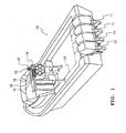
- Figs. 1 through 6 show an embodiment of the invention.
- reference numeral 10 denotes a boat having at the rear of its hull plural outboard motors 11.
- the boat 10 has an inboard network system.
- a network cable 13 of the inboard network system is connected to the four outboard motors 11 of this embodiment.
- indicating devices 15 for indicating various information on the outboard motors, a steering device 16, a remote control 17 and the like for controlling the boat, and various intelligent devices (not shown).
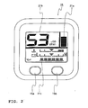
- the indicating device 15 of the boat operating section 14 is provided with a trim angle indicating section 21 a for indicating the trim angle of the outboard motor 11, an engine speed indicating section 21 b for indicating engine speed, an engine condition indicating section 21c for indicating engine conditions such as cooling water temperature and hydraulic pressure, and the like, as shown in Fig. 2 .
- the indicating device 15 is also provided with input switches 15a, 15b for various input control such as switching between normal mode and setting mode.
- one outboard motor 11 corresponds to one indicating device 15.
- the trim angle of the outboard motor 11 detected by a detector 31 which is disposed in the outboard motor 11 is indicated in the corresponding trim angle indicating section 21 a.
- a trim angle correction indicating system 20 is provided for indicating the trim angle with good accuracy.
- the outboard motor 11 is mounted on the hull, as shown in Fig. 3 . More specifically, the outboard motor 11 is mounted on the hull 10a to be rotationally movable in a way such that a clamp bracket 23 secured to the hull 10a and a swivel bracket 25 secured to the outboard motor 11 are connected together by a tilt shaft 27 so that the swivel bracket 25 rotationally moves in relation to the clamp bracket 23. As shown in Fig. 4 and Fig.
- the detector 31 is mounted in a way such that a base 32 of the detector 31 is secured to the clamp bracket 23 and a detecting section 33 disposed on the base 32 for free rotational movement is connected to the swivel bracket 25 through a linkage 34.
- the linkage 34 moves between the original position and the position shown in Fig. 4 by phantom lines, in accordance with the rotational movement of the swivel bracket 25, so that the detecting section 33 rotationally moves.
- the outboard motor 11 In the outboard motor 11, the lowest position at which the outboard motor 11 is placed when raised vertically, the full trim-in position, is set as a reference position, as shown in Fig. 3 by solid lines.
- a stopper (not shown) is disposed for stopping the rotational movement of the outboard motor 11 when the outboard motor 11 is brought to the reference position and the swivel bracket 25 comes in contact with the stopper.
- the detecting section 33 of the detector 31 rotationally moves in relation to the base 32 and a contact point 37 moves toward a resistance plate 36 inside the detector, as shown in Fig. 3 to Fig. 5 .
- the value of resistance changes in accordance with the displacement of the swivel bracket 25 in relation to the clamp bracket 23, and the value of voltage corresponding to the trim angle of the outboard motor 11 is obtained from the detector 31 as a detection value.
- the detection value is transmitted to an ECU (engine control unit) (not shown) of the outboard motor 11.
- the trim angle correction indicating system 20 for an outboard motor of this embodiment indicates the trim angle of the outboard motor 11 in the trim angle indicating section 21 a, based on the detection value obtained from such detector 31.
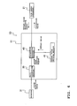
- the ECU of the outboard motor 11 has a unit converting section 39 for converting the detection value obtained from the detector 31 to a trim position signal, an offset value setting section 41 for setting a predetermined offset value, and a correction processing section 43 for correcting the trim position signal of the detection value based on the offset value to provide a correction value.
- the correction value is sent to the trim angle indicating section 21 a via the network cable 13, and then the trim angle of the outboard motor 11 is indicated based on the correction value.
- the predetermined offset value is set as the detection value obtained from the detector 31 when the outboard motor 11 is placed at the reference position, and converted to the trim position signal.
- the trim position signal is a signal capable of being sent via the inboard network system and indicating the trim angle when inputted in the trim angle indicating section 21 a.
- the indicating device 15 having the trim angle indicating section 21 a is provided with the switches 15a, 15b as an offset value obtaining instruction section for generating the signal to cause the offset value setting section 41 to set an offset value. Controlling from the indicating device 15 allows the offset value to be set when the outboard motor 11 is placed at the reference position.
- the trim angle correction indicating system 20 for an outboard motor in order to mechanically specify the reference position of the outboard motor 11 during its rotational movement, it is determined that the outboard motor 11 is brought to the reference position, when its rotational movement is stopped at a specified position for a specified period of time, thereby causing the offset value setting section 41 to set the offset value.
- trim angle correction indicating system 20 for an outboard motor with the foregoing configuration, the trim angle of the outboard motor 11 is indicated in the trim angle indicating section 21 a as follows.
- the operator first controls the switches 15a, 15b of the indicating device 15 to switch to the mode for causing the offset value setting section 41 to set an offset value, and then an offset value obtaining signal is sent from an indicator 21 to the ECU of the outboard motor 11 via the network cable 13, as shown in Fig. 6 . Then, when the outboard motor 11 is rotationally moved to be raised while the system is in that state, the outboard motor 11 comes in contact with the stopper and stops, so that it is placed at the reference position. Thereafter, any further rotational movement of the outboard motor 11 is prevented, and the detection value obtained from the detector 31 is held at a constant value and does not change.
- detecting the specified time elapsed when no detection value changes during the rotational movement of the outboard motor 11, indicates that the outboard motor 11 is placed at the reference position.
- the detection value then obtained from the detector 31 is converted to a trim position signal by the unit converting section 39, which is then automatically set as an offset value by the offset value setting section 41.
- the stopper may be provided with a switch, for example, which is activated for detection when the outboard motor 11 is brought to the reference position.
- the operator then controls the switches 15a, 15b of the indicating device 15 to switch to the normal detection mode, so that the trim angle of the outboard motor 11 is detected by the detector 31.
- the detection value detected by the detector 31 is sent to the ECU of the outboard motor 11 and converted to a trim position signal by the unit converting section 39.
- the trim position signal is then corrected based on the offset value set by the offset value setting section 41 by the correction processing section 43 computing the difference between the two values, for example, so that a correction value is obtained.
- the correction value is sent to the trim angle indicating section 21 a via the network cable 13, and the trim angle of the outboard motor 11 is indicated in the trim angle indicating section 21 a.
- the offset value setting section 41 sets the detection value obtained from the detector 31 when the outboard motor 11 is placed at the reference position, as an offset value.
- the correction processing section 43 corrects the detection value obtained from the detector 31 by using the offset value. Based on the correction value thereby obtained, the trim angle of the outboard motor 11 is indicated in the trim angle indicating section 21 a. Therefore, the occurrence of misalignment of the detector 31 and deviation in the detection value obtained from the detector 31 due to its change over time can be compensated by the offset value. Correcting the detection value obtained from the detector 31 by using the offset value provides the correction value with such misalignment and deviation compensated.
- the trim angle of the outboard motor 11 can be indicated in the trim angle indicating section 21 a with good accuracy, if it is determined based on the correction value.
- the detecting section 33, the offset value setting section 41, and the correction processing section 43 are all disposed in the outboard motor 11. Therefore, misalignment, deviation in detection value, and the like which occur only at the outboard motor 11 can be compensated at the outboard motor 11 so that an accurate correction value is obtained therefrom.
- the accurate correction value is always sent to the trim angle indicating section 21 a. Therefore, there is no need to make an adjustment that compensates such misalignment and deviation which occur at the outboard motor 11 in the trim angle indicating section 21 a, and the trim angle indicating section 21a can be made with a simple construction.
- the detector 31 and the trim angle indicating section 21 a are connected together via the network cable 13 in such a manner as described, removal and replacement of the indicating device 15 having the trim angle indicating section 21 a is facilitated. Since the offset value is set at the outboard motor 11 side, there is no need for the operator to control to reset the offset value when the indicating device 15 is replaced, which allows easy replacement.
- the switches 15a, 15b for causing the offset value setting operation to start are located in the indicating device 15 having the trim angle indicating section 21 a. Therefore, the operator can give an offset value setting instruction while operating the boat, which provides good operability.
- the system is configured such that it has the stopper for stopping the rotational movement of the outboard motor 11 at the reference position, and when the rotational movement of the outboard motor 11 is stopped at the reference position for a specified period of time, an offset value is set by the offset value setting section 41. This facilitates automatically detecting that the outboard motor 11 is placed at the reference position and setting the offset value.
- the offset value setting section 41 and the correction processing section 43 are both disposed in the outboard motor 11.
- the offset value setting section 41 and the correction processing section 43 can be disposed at the trim angle indicating section 21 a side, as shown in Fig. 7 .
- the detection value is transmitted from the detector 31 to the ECU of the outboard motor 11, where the detection value is converted to a trim position signal by the unit converting device 39, and then the trim position signal is sent via the network cable 13.
- the trim position signal is then corrected by use of the offset value set at the trim angle indicating section 21 a side, to determine the correction value, and the trim angle is indicated in the trim angle indicating section 21 a based on the correction value.
- the invention provides a trim angle (correction) indicating system for an outboard motor capable of indicating the trim angle of the outboard motor with good accuracy, in particular also when misalignment of the detector and deviation in detection value occur.
- a trim angle correction indicating system for an outboard motor having a detector for detecting the trim angle of an outboard motor, and a trim angle indicating section for indicating the trim angle detected by the detector, comprising: an offset value setting section for setting the detection value detected by the detector when the outboard motor is placed at a reference position, as an offset value; and a correction processing section for correcting the detection value detected by the detector based on the offset value set by the offset value setting section, in which the trim angle of the outboard motor is indicated in the trim angle indicating section based on the correction value provided by the correction processing section correcting the detection value.
- the detector mounted to the outboard motor and the trim angle indicating section are connected together via a network, and the offset value setting section and the correction processing section are disposed in the outboard motor.
- switches for causing the offset value setting section to start offset value setting operation are disposed in the trim angle indicating section.
- a stopper is provided for stopping the rotational movement of the outboard motor at the reference position, in which when the rotational movement of the outboard motor is stopped at the reference position for a specified period of time, the offset value is set by the offset value setting section.
- the offset value setting section sets the detection value obtained from the detector when the outboard motor is placed at the reference position, as the offset value.
- the correction processing section corrects the detection value obtained from the detector by using the offset value. Based on the correction value thereby obtained, the trim angle of the outboard motor is indicated in the trim angle indicating section. Therefore, the occurrence of misalignment of the detector and deviation in detection value obtained from the detector due to its change over time can be compensated by the offset value. Correcting the detection value obtained from the detector by using the offset value provides the correction value with such misalignment and deviation compensated.
- the trim angle of the outboard motor can be indicated in the trim angle indicating section with good accuracy, if it is determined based on the correction value.
- the detecting section, the offset value setting section, and the correction processing section are all disposed in the outboard motor. Therefore, an accurate correction value with misalignment, deviation in detection value, and the like which occur at the outboard motor compensated can be obtained from the outboard motor. Thus, the accurate correction value is always sent to the trim angle indicating section. Therefore, there is no need to make an adjustment that compensates such misalignment and deviation which occur at the outboard motor in the trim angle indicating section, and the trim angle indicating section can be made with a simple construction.
- the trim angle indicating section is separated from the network for replacement, since the offset value is set at the outboard motor side, there is no need for the operator to control to reset the offset value, which allows easy replacement of the trim angle indicating section.
- the switches for causing the offset value setting operation to start are disposed in the trim angle indicating section. Therefore, the operator can give an offset value setting instruction while operating the boat, which provides good operability.
- the system is configured such that it has the stopper for stopping the rotational movement of the outboard motor at the reference position, and when the rotational movement of the outboard motor is stopped at the reference position for a specified period of time, the offset value is set by the offset value setting section. This allows automatically detecting that the outboard motor is placed at the reference position and setting the offset value.
- a trim angle correction indicating system 20 for an outboard motor having a detector 31 for detecting the trim angle of an outboard motor 11, and a trim angle indicating section 21 a for indicating the trim angle detected by the detector 31, comprising: an offset value setting section 41 for setting the detection value detected by the detector 31 when the outboard motor 11 is placed at a reference position, as an offset value; and a correction processing section 43 for correcting the detection value detected by the detector 31 based on the offset value set by the offset value setting section 41, in which the trim angle of the outboard motor 11 is indicated in the trim angle indicating section 21 a based on the correction value provided by the correction processing section 43 correcting the detection value.
Landscapes
- Chemical & Material Sciences (AREA)
- Engineering & Computer Science (AREA)
- Combustion & Propulsion (AREA)
- Mechanical Engineering (AREA)
- Ocean & Marine Engineering (AREA)
- Transmission And Conversion Of Sensor Element Output (AREA)
- Instrument Panels (AREA)
- Measurement Of Length, Angles, Or The Like Using Electric Or Magnetic Means (AREA)
- Control Of Electric Motors In General (AREA)
- Fittings On The Vehicle Exterior For Carrying Loads, And Devices For Holding Or Mounting Articles (AREA)
- Length Measuring Devices With Unspecified Measuring Means (AREA)
- Control Of Position Or Direction (AREA)
Claims (10)
- Trimmwinkel- Anzeigesystem für einen Außenbordmotor mit einem Erfasser (31) zum Erfassen eines Trimmwinkelwertes eines Außenbordmotors (11) und einer Trimmwinkel- Anzeigevorrichtung (15) zum Anzeigen des Trimmwinkelwertes, gekennzeichnet durch das Aufweisen eines Korrekturverarbeitungsabschnittes (43), konfiguriert, den erfassten Trimmwinkelwert in Übereinstimmung mit einer Referenzposition des Außenbordmotors (11) zu korrigieren.
- Trimmwinkel- Anzeigesystem nach Anspruch 1, gekennzeichnet durch außerdem aufweisend eines Versatzwert- Festlegungsabschnitt (41), konfiguriert, einen erfassten Trimmwinkelwert, der durch den Erfasser (31) erfasst wird, als einen Versatzwert festzulegen, wenn der Außenbordmotor (11) in der Referenzposition platziert ist.
- Trimmwinkel- Anzeigesystem nach Anspruch 2, dadurch gekennzeichnet, dass der Korrekturverarbeitungsabschnitt (43) konfiguriert ist, einen korrigierten Erfassungswert auf der Grundlage eines momentan erfassten Trimmwinkelwertes und des Versatzwertes, festgelegt durch den Versatzwert- Festlegungsabschnitt (41), festzulegen.
- Trimmwinkel- Anzeigesystem nach zumindest einem der Ansprüche 1 bis 3, dadurch gekennzeichnet, dass die Trimmwinkel- Anzeigevorrichtung (15) konfiguriert ist, den korrigierten Trimmwinkelwert, geschaffen durch den Korrekturverarbeitungsabschnitt (43), anzuzeigen.
- Trimmwinkel- Anzeigesystem nach zumindest einem der Ansprüche 1 bis 4, dadurch gekennzeichnet, dass das System konfiguriert ist, einen Trimmwinkel-Anzeigemodus zu schaffen, währenddessen ein Trimmwinkelwert durch die Anzeigevorrichtung (15) angezeigt wird, und einen Versatzwert- Festlegungsvorgang zu schaffen, währenddessen ein Versatzwert festgelegt wird.
- Trimmwinkel- Anzeigesystem nach zumindest einem der Ansprüche 1 bis 5, dadurch gekennzeichnet, dass der Erfasser (31) an dem Außenbordmotor (11) montiert ist und mit dem Trimmwinkel- Anzeigeabschnitt (21 a) über ein Netzwerk verbunden ist.
- Trimmwinkel- Anzeigesystem nach zumindest einem der Ansprüche 1 bis 6, dadurch gekennzeichnet, dass der Versatzwert- Festlegungsabschnitt (41) und / oder der Korrekturverarbeitungsabschnitt (43) in dem Außenbordmotor (11) und / oder in der Trimmwinkel- Anzeigevorrichtung (15) angeordnet sind.
- Trimmwinkel- Anzeigesystem nach zumindest einem der Ansprüche 2 bis 7, dadurch gekennzeichnet, dass Schalter (15a, 15b), um den Versatzwert- Festlegungsabschnitt (41) zu veranlassen, einen Versatzwert- Festlegungsvorgang zu starten, in der Trimmwinkel- Anzeigevorrichtung (15) angeordnet sind.
- Trimmwinkel- Anzeigesystem nach zumindest einem der Ansprüche 2 bis 8, gekennzeichnet durch einen Anschlag, konfiguriert, eine Drehbewegung des Außenbordmotors (11) in der Referenzposition zu begrenzen, wobei vorzugsweise, wenn die Drehbewegung des Außenbordmotors (11) in der Referenzposition für einen bestimmten Zeitraum gestoppt ist, der Versatzwert durch den Versatzwert-Festlegungsabschnitt (41) festgelegt wird.
- Trimmwinkel- Anzeigesystem nach zumindest einem der Ansprüche 1 bis 9, dadurch gekennzeichnet, dass ein Schalter vorgesehen ist, konfiguriert, um aktiviert zu sein, wenn der Außenbordmotor (11) in die Referenzposition gebracht wird.
Applications Claiming Priority (2)
| Application Number | Priority Date | Filing Date | Title |
|---|---|---|---|
| JP2003400615A JP4319016B2 (ja) | 2003-11-28 | 2003-11-28 | 船外機用トリム角補正表示装置 |
| JP2003400615 | 2003-11-28 |
Publications (3)
| Publication Number | Publication Date |
|---|---|
| EP1535833A2 EP1535833A2 (de) | 2005-06-01 |
| EP1535833A3 EP1535833A3 (de) | 2008-08-13 |
| EP1535833B1 true EP1535833B1 (de) | 2009-12-30 |
Family
ID=34463905
Family Applications (1)
| Application Number | Title | Priority Date | Filing Date |
|---|---|---|---|
| EP04025199A Expired - Lifetime EP1535833B1 (de) | 2003-11-28 | 2004-10-22 | Anzeigeeinrichtung des Trimmwinkels eines Aussenbordmotors |
Country Status (5)
| Country | Link |
|---|---|
| US (1) | US7059922B2 (de) |
| EP (1) | EP1535833B1 (de) |
| JP (1) | JP4319016B2 (de) |
| AT (1) | ATE453567T1 (de) |
| DE (1) | DE602004024859D1 (de) |
Families Citing this family (22)
| Publication number | Priority date | Publication date | Assignee | Title |
|---|---|---|---|---|
| US7571032B2 (en) * | 2004-01-06 | 2009-08-04 | Yamaha Hatsudoki Kabushiki Kaisha | Display device for watercraft |
| JP4327617B2 (ja) | 2004-01-29 | 2009-09-09 | ヤマハ発動機株式会社 | 船舶推進装置のステアリング制御方法 |
| JP2006001432A (ja) * | 2004-06-18 | 2006-01-05 | Yamaha Marine Co Ltd | 小型船舶用ステアリング装置 |
| JP4938271B2 (ja) | 2005-09-02 | 2012-05-23 | ヤマハ発動機株式会社 | 船舶の操舵方法及び操舵装置 |
| JP2007050823A (ja) * | 2005-08-19 | 2007-03-01 | Yamaha Marine Co Ltd | 小型船舶の挙動制御装置 |
| JP4658742B2 (ja) * | 2005-09-02 | 2011-03-23 | ヤマハ発動機株式会社 | 小型船舶のステアリング装置 |
| JP4673187B2 (ja) | 2005-10-25 | 2011-04-20 | ヤマハ発動機株式会社 | 多機掛け推進機の制御装置 |
| JP4732860B2 (ja) * | 2005-11-04 | 2011-07-27 | ヤマハ発動機株式会社 | 船外機用電動式操舵装置 |
| EP1999011B1 (de) * | 2006-03-16 | 2013-07-10 | CPAC Systems AB | Schiffsantriebssteuersystem und solch ein schiffsantriebssteuersystem enthaltendes schiff |
| JP5132132B2 (ja) * | 2006-11-17 | 2013-01-30 | ヤマハ発動機株式会社 | 船舶用操舵装置及び船舶 |
| JP2008126775A (ja) * | 2006-11-17 | 2008-06-05 | Yamaha Marine Co Ltd | 船舶用転舵装置、及び船舶 |
| JP4884177B2 (ja) * | 2006-11-17 | 2012-02-29 | ヤマハ発動機株式会社 | 船舶用操舵装置及び船舶 |
| CN101342940B (zh) * | 2007-12-29 | 2010-06-30 | 上海海事大学 | 一种水面自行载体的推进器的变位装置 |
| JP5062023B2 (ja) * | 2008-05-09 | 2012-10-31 | スズキ株式会社 | 船外機の傾斜角制御装置 |
| JP5737986B2 (ja) * | 2011-02-08 | 2015-06-17 | 朝日電装株式会社 | チルト位置検知装置 |
| US9376193B1 (en) | 2011-05-31 | 2016-06-28 | Brp Us Inc. | Marine outboard engine angular position limitation system and method |
| US10214273B1 (en) * | 2018-02-01 | 2019-02-26 | Brunswick Corporation | System and method for controlling propulsion of a marine vessel |
| US11372411B1 (en) | 2019-08-08 | 2022-06-28 | Brunswick Corporation | Marine steering system and method |
| US12065230B1 (en) | 2022-02-15 | 2024-08-20 | Brunswick Corporation | Marine propulsion control system and method with rear and lateral marine drives |
| US12110088B1 (en) | 2022-07-20 | 2024-10-08 | Brunswick Corporation | Marine propulsion system and method with rear and lateral marine drives |
| US12258115B2 (en) | 2022-07-20 | 2025-03-25 | Brunswick Corporation | Marine propulsion system and joystick control method |
| US12134454B1 (en) | 2022-07-20 | 2024-11-05 | Brunswick Corporation | Marine propulsion system and method with single rear drive and lateral marine drive |
Family Cites Families (13)
| Publication number | Priority date | Publication date | Assignee | Title |
|---|---|---|---|---|
| US3641965A (en) * | 1970-10-05 | 1972-02-15 | Brunswick Corp | Trim indicator system |
| SE451446B (sv) * | 1983-09-20 | 1987-10-12 | Volvo Penta Ab | Trimindikator for batar med utombordspropellerdrev |
| US5352137A (en) * | 1985-05-18 | 1994-10-04 | Sanshin Kogyo Kabushiki Kaisha | Automatic position controller for marine propulsions |
| JPH0631073B2 (ja) * | 1985-10-02 | 1994-04-27 | 三信工業株式会社 | 船舶用推進ユニツトのトリム角制御装置 |
| JPH0627977B2 (ja) | 1986-09-08 | 1994-04-13 | ヤマハ発動機株式会社 | 船舶推進機のトリム角表示装置 |
| JPS63301196A (ja) * | 1987-05-29 | 1988-12-08 | Sanshin Ind Co Ltd | 船舶の姿勢制御装置 |
| JPH0764312B2 (ja) | 1987-07-09 | 1995-07-12 | 三信工業株式会社 | 船舶推進機の傾斜角検出器調整方法 |
| JPH02237893A (ja) * | 1989-03-10 | 1990-09-20 | Showa Mfg Co Ltd | ボート用推進ユニットのトリム角制御方法 |
| JP2759485B2 (ja) | 1989-04-14 | 1998-05-28 | 三信工業株式会社 | 船舶推進機のトリム検出装置 |
| JPH04325740A (ja) * | 1991-04-26 | 1992-11-16 | Mitsubishi Electric Corp | 船外機用内燃機関制御装置 |
| US5167546A (en) * | 1991-08-14 | 1992-12-01 | Outboard Marine Corporation | Automatic trim system |
| US5647780A (en) * | 1995-06-07 | 1997-07-15 | Yamaha Hatsudoki Kabushiki Kaisha | Vertically adjustable stern drive for watercraft |
| JP2000130244A (ja) * | 1998-10-26 | 2000-05-09 | Sanshin Ind Co Ltd | エンジン回転数表示装置 |
-
2003
- 2003-11-28 JP JP2003400615A patent/JP4319016B2/ja not_active Expired - Lifetime
-
2004
- 2004-10-20 US US10/969,642 patent/US7059922B2/en not_active Expired - Lifetime
- 2004-10-22 DE DE602004024859T patent/DE602004024859D1/de not_active Expired - Lifetime
- 2004-10-22 EP EP04025199A patent/EP1535833B1/de not_active Expired - Lifetime
- 2004-10-22 AT AT04025199T patent/ATE453567T1/de not_active IP Right Cessation
Also Published As
| Publication number | Publication date |
|---|---|
| US20050118894A1 (en) | 2005-06-02 |
| EP1535833A2 (de) | 2005-06-01 |
| ATE453567T1 (de) | 2010-01-15 |
| US7059922B2 (en) | 2006-06-13 |
| DE602004024859D1 (de) | 2010-02-11 |
| EP1535833A3 (de) | 2008-08-13 |
| JP2005161905A (ja) | 2005-06-23 |
| JP4319016B2 (ja) | 2009-08-26 |
Similar Documents
| Publication | Publication Date | Title |
|---|---|---|
| EP1535833A2 (de) | Anzeigeeinrichtung des Trimmwinkels eines Aussenbordmotors | |
| US10155578B1 (en) | Method and system for controlling a marine drive during shift sensor fault | |
| US6587765B1 (en) | Electronic control system for marine vessels | |
| US4861291A (en) | Marine engine protection device | |
| JP2980943B2 (ja) | 舶用推進機の遠隔制御シフト装置 | |
| EP1094380B1 (de) | Winkelmesseinrichtung | |
| US8165736B2 (en) | Control device for watercrafts | |
| US5982131A (en) | Control device for motor driving system | |
| US8229608B2 (en) | Outboard motor control apparatus | |
| US6327976B1 (en) | Method for detecting a rotation angle position of moveable cylinder of a printing machine | |
| JP2005297578A (ja) | 輪転印刷機 | |
| US5094637A (en) | Trim detecting device for marine propulsion device | |
| CN113452294A (zh) | 一种机械式车速表的车速指示控制方法、系统及汽车 | |
| JP5218033B2 (ja) | スニップシャーのクランク軸の零調方法 | |
| US6321592B1 (en) | Method and apparatus for calibrating a position sensor used in engine control | |
| US4841859A (en) | Side lay control apparatus for sheet-fed printing press | |
| US4855733A (en) | Inclination detector adjusting device for vessel propulsion unit | |
| JP2652836B2 (ja) | 印刷装置のインキ制御装置 | |
| US20250263117A1 (en) | Steering Device and Method for Operating the Steering Device | |
| JP4814193B2 (ja) | エンジンの電子ガバナ | |
| KR100250030B1 (ko) | 스티어링 중립 보정장치 | |
| JPH07170775A (ja) | 位置調整機構のモータ制御方法およびモータ制御装置 | |
| KR0149352B1 (ko) | 엔진 냉각수온 감지장치 고장 판정시 감지신호 보상방법 | |
| JPH02121867A (ja) | プリンタ装置 | |
| JPH1034889A (ja) | インキ壺の原点位置調整装置 |
Legal Events
| Date | Code | Title | Description |
|---|---|---|---|
| PUAI | Public reference made under article 153(3) epc to a published international application that has entered the european phase |
Free format text: ORIGINAL CODE: 0009012 |
|
| AK | Designated contracting states |
Kind code of ref document: A2 Designated state(s): AT BE BG CH CY CZ DE DK EE ES FI FR GB GR HU IE IT LI LU MC NL PL PT RO SE SI SK TR |
|
| AX | Request for extension of the european patent |
Extension state: AL HR LT LV MK |
|
| PUAL | Search report despatched |
Free format text: ORIGINAL CODE: 0009013 |
|
| AK | Designated contracting states |
Kind code of ref document: A3 Designated state(s): AT BE BG CH CY CZ DE DK EE ES FI FR GB GR HU IE IT LI LU MC NL PL PT RO SE SI SK TR |
|
| AX | Request for extension of the european patent |
Extension state: AL HR LT LV MK |
|
| 17P | Request for examination filed |
Effective date: 20090113 |
|
| AKX | Designation fees paid |
Designated state(s): AT BE BG CH CY CZ DE DK EE ES FI FR GB GR HU IE IT LI LU MC NL PL PT RO SE SI SK TR |
|
| GRAP | Despatch of communication of intention to grant a patent |
Free format text: ORIGINAL CODE: EPIDOSNIGR1 |
|
| GRAS | Grant fee paid |
Free format text: ORIGINAL CODE: EPIDOSNIGR3 |
|
| GRAA | (expected) grant |
Free format text: ORIGINAL CODE: 0009210 |
|
| AK | Designated contracting states |
Kind code of ref document: B1 Designated state(s): AT BE BG CH CY CZ DE DK EE ES FI FR GB GR HU IE IT LI LU MC NL PL PT RO SE SI SK TR |
|
| REG | Reference to a national code |
Ref country code: GB Ref legal event code: FG4D |
|
| REG | Reference to a national code |
Ref country code: CH Ref legal event code: EP |
|
| REG | Reference to a national code |
Ref country code: IE Ref legal event code: FG4D |
|
| REF | Corresponds to: |
Ref document number: 602004024859 Country of ref document: DE Date of ref document: 20100211 Kind code of ref document: P |
|
| PG25 | Lapsed in a contracting state [announced via postgrant information from national office to epo] |
Ref country code: FI Free format text: LAPSE BECAUSE OF FAILURE TO SUBMIT A TRANSLATION OF THE DESCRIPTION OR TO PAY THE FEE WITHIN THE PRESCRIBED TIME-LIMIT Effective date: 20091230 Ref country code: SE Free format text: LAPSE BECAUSE OF FAILURE TO SUBMIT A TRANSLATION OF THE DESCRIPTION OR TO PAY THE FEE WITHIN THE PRESCRIBED TIME-LIMIT Effective date: 20091230 |
|
| REG | Reference to a national code |
Ref country code: NL Ref legal event code: VDEP Effective date: 20091230 |
|
| PG25 | Lapsed in a contracting state [announced via postgrant information from national office to epo] |
Ref country code: SI Free format text: LAPSE BECAUSE OF FAILURE TO SUBMIT A TRANSLATION OF THE DESCRIPTION OR TO PAY THE FEE WITHIN THE PRESCRIBED TIME-LIMIT Effective date: 20091230 Ref country code: PL Free format text: LAPSE BECAUSE OF FAILURE TO SUBMIT A TRANSLATION OF THE DESCRIPTION OR TO PAY THE FEE WITHIN THE PRESCRIBED TIME-LIMIT Effective date: 20091230 |
|
| PG25 | Lapsed in a contracting state [announced via postgrant information from national office to epo] |
Ref country code: AT Free format text: LAPSE BECAUSE OF FAILURE TO SUBMIT A TRANSLATION OF THE DESCRIPTION OR TO PAY THE FEE WITHIN THE PRESCRIBED TIME-LIMIT Effective date: 20091230 |
|
| PG25 | Lapsed in a contracting state [announced via postgrant information from national office to epo] |
Ref country code: BG Free format text: LAPSE BECAUSE OF FAILURE TO SUBMIT A TRANSLATION OF THE DESCRIPTION OR TO PAY THE FEE WITHIN THE PRESCRIBED TIME-LIMIT Effective date: 20100330 Ref country code: EE Free format text: LAPSE BECAUSE OF FAILURE TO SUBMIT A TRANSLATION OF THE DESCRIPTION OR TO PAY THE FEE WITHIN THE PRESCRIBED TIME-LIMIT Effective date: 20091230 Ref country code: ES Free format text: LAPSE BECAUSE OF FAILURE TO SUBMIT A TRANSLATION OF THE DESCRIPTION OR TO PAY THE FEE WITHIN THE PRESCRIBED TIME-LIMIT Effective date: 20100410 Ref country code: NL Free format text: LAPSE BECAUSE OF FAILURE TO SUBMIT A TRANSLATION OF THE DESCRIPTION OR TO PAY THE FEE WITHIN THE PRESCRIBED TIME-LIMIT Effective date: 20091230 Ref country code: RO Free format text: LAPSE BECAUSE OF FAILURE TO SUBMIT A TRANSLATION OF THE DESCRIPTION OR TO PAY THE FEE WITHIN THE PRESCRIBED TIME-LIMIT Effective date: 20091230 Ref country code: PT Free format text: LAPSE BECAUSE OF FAILURE TO SUBMIT A TRANSLATION OF THE DESCRIPTION OR TO PAY THE FEE WITHIN THE PRESCRIBED TIME-LIMIT Effective date: 20100430 |
|
| REG | Reference to a national code |
Ref country code: FR Ref legal event code: TP |
|
| PG25 | Lapsed in a contracting state [announced via postgrant information from national office to epo] |
Ref country code: BE Free format text: LAPSE BECAUSE OF FAILURE TO SUBMIT A TRANSLATION OF THE DESCRIPTION OR TO PAY THE FEE WITHIN THE PRESCRIBED TIME-LIMIT Effective date: 20091230 Ref country code: SK Free format text: LAPSE BECAUSE OF FAILURE TO SUBMIT A TRANSLATION OF THE DESCRIPTION OR TO PAY THE FEE WITHIN THE PRESCRIBED TIME-LIMIT Effective date: 20091230 Ref country code: CZ Free format text: LAPSE BECAUSE OF FAILURE TO SUBMIT A TRANSLATION OF THE DESCRIPTION OR TO PAY THE FEE WITHIN THE PRESCRIBED TIME-LIMIT Effective date: 20091230 |
|
| PG25 | Lapsed in a contracting state [announced via postgrant information from national office to epo] |
Ref country code: CY Free format text: LAPSE BECAUSE OF FAILURE TO SUBMIT A TRANSLATION OF THE DESCRIPTION OR TO PAY THE FEE WITHIN THE PRESCRIBED TIME-LIMIT Effective date: 20091230 Ref country code: GR Free format text: LAPSE BECAUSE OF FAILURE TO SUBMIT A TRANSLATION OF THE DESCRIPTION OR TO PAY THE FEE WITHIN THE PRESCRIBED TIME-LIMIT Effective date: 20100331 |
|
| PLBE | No opposition filed within time limit |
Free format text: ORIGINAL CODE: 0009261 |
|
| STAA | Information on the status of an ep patent application or granted ep patent |
Free format text: STATUS: NO OPPOSITION FILED WITHIN TIME LIMIT |
|
| 26N | No opposition filed |
Effective date: 20101001 |
|
| PG25 | Lapsed in a contracting state [announced via postgrant information from national office to epo] |
Ref country code: DK Free format text: LAPSE BECAUSE OF FAILURE TO SUBMIT A TRANSLATION OF THE DESCRIPTION OR TO PAY THE FEE WITHIN THE PRESCRIBED TIME-LIMIT Effective date: 20091230 |
|
| PG25 | Lapsed in a contracting state [announced via postgrant information from national office to epo] |
Ref country code: IT Free format text: LAPSE BECAUSE OF FAILURE TO SUBMIT A TRANSLATION OF THE DESCRIPTION OR TO PAY THE FEE WITHIN THE PRESCRIBED TIME-LIMIT Effective date: 20091230 |
|
| PG25 | Lapsed in a contracting state [announced via postgrant information from national office to epo] |
Ref country code: MC Free format text: LAPSE BECAUSE OF NON-PAYMENT OF DUE FEES Effective date: 20101031 |
|
| REG | Reference to a national code |
Ref country code: CH Ref legal event code: PL |
|
| PG25 | Lapsed in a contracting state [announced via postgrant information from national office to epo] |
Ref country code: LI Free format text: LAPSE BECAUSE OF NON-PAYMENT OF DUE FEES Effective date: 20101031 Ref country code: CH Free format text: LAPSE BECAUSE OF NON-PAYMENT OF DUE FEES Effective date: 20101031 |
|
| PG25 | Lapsed in a contracting state [announced via postgrant information from national office to epo] |
Ref country code: IE Free format text: LAPSE BECAUSE OF NON-PAYMENT OF DUE FEES Effective date: 20101022 |
|
| PG25 | Lapsed in a contracting state [announced via postgrant information from national office to epo] |
Ref country code: HU Free format text: LAPSE BECAUSE OF FAILURE TO SUBMIT A TRANSLATION OF THE DESCRIPTION OR TO PAY THE FEE WITHIN THE PRESCRIBED TIME-LIMIT Effective date: 20100701 Ref country code: LU Free format text: LAPSE BECAUSE OF NON-PAYMENT OF DUE FEES Effective date: 20101022 |
|
| PG25 | Lapsed in a contracting state [announced via postgrant information from national office to epo] |
Ref country code: TR Free format text: LAPSE BECAUSE OF FAILURE TO SUBMIT A TRANSLATION OF THE DESCRIPTION OR TO PAY THE FEE WITHIN THE PRESCRIBED TIME-LIMIT Effective date: 20091230 |
|
| REG | Reference to a national code |
Ref country code: FR Ref legal event code: PLFP Year of fee payment: 12 |
|
| REG | Reference to a national code |
Ref country code: FR Ref legal event code: PLFP Year of fee payment: 13 |
|
| REG | Reference to a national code |
Ref country code: FR Ref legal event code: PLFP Year of fee payment: 14 |
|
| REG | Reference to a national code |
Ref country code: FR Ref legal event code: PLFP Year of fee payment: 15 |
|
| PGFP | Annual fee paid to national office [announced via postgrant information from national office to epo] |
Ref country code: GB Payment date: 20231020 Year of fee payment: 20 |
|
| PGFP | Annual fee paid to national office [announced via postgrant information from national office to epo] |
Ref country code: FR Payment date: 20231023 Year of fee payment: 20 Ref country code: DE Payment date: 20231020 Year of fee payment: 20 |
|
| REG | Reference to a national code |
Ref country code: DE Ref legal event code: R071 Ref document number: 602004024859 Country of ref document: DE |
|
| REG | Reference to a national code |
Ref country code: GB Ref legal event code: PE20 Expiry date: 20241021 |
|
| PG25 | Lapsed in a contracting state [announced via postgrant information from national office to epo] |
Ref country code: GB Free format text: LAPSE BECAUSE OF EXPIRATION OF PROTECTION Effective date: 20241021 |
|
| PG25 | Lapsed in a contracting state [announced via postgrant information from national office to epo] |
Ref country code: GB Free format text: LAPSE BECAUSE OF EXPIRATION OF PROTECTION Effective date: 20241021 |