EP1535713B1 - Kontinuierliches Formen von Befestigungsprodukten und dergleichen sowie auf diese Weise hergestellte Produkte - Google Patents
Kontinuierliches Formen von Befestigungsprodukten und dergleichen sowie auf diese Weise hergestellte Produkte Download PDFInfo
- Publication number
- EP1535713B1 EP1535713B1 EP05000856A EP05000856A EP1535713B1 EP 1535713 B1 EP1535713 B1 EP 1535713B1 EP 05000856 A EP05000856 A EP 05000856A EP 05000856 A EP05000856 A EP 05000856A EP 1535713 B1 EP1535713 B1 EP 1535713B1
- Authority
- EP
- European Patent Office
- Prior art keywords
- roll
- mold
- pressure
- nip
- load
- Prior art date
- Legal status (The legal status is an assumption and is not a legal conclusion. Google has not performed a legal analysis and makes no representation as to the accuracy of the status listed.)
- Expired - Lifetime
Links
Images






Classifications
-
- A—HUMAN NECESSITIES
- A44—HABERDASHERY; JEWELLERY
- A44B—BUTTONS, PINS, BUCKLES, SLIDE FASTENERS, OR THE LIKE
- A44B18/00—Fasteners of the touch-and-close type; Making such fasteners
- A44B18/0046—Fasteners made integrally of plastics
- A44B18/0049—Fasteners made integrally of plastics obtained by moulding processes
-
- A—HUMAN NECESSITIES
- A44—HABERDASHERY; JEWELLERY
- A44B—BUTTONS, PINS, BUCKLES, SLIDE FASTENERS, OR THE LIKE
- A44B18/00—Fasteners of the touch-and-close type; Making such fasteners
- A44B18/0046—Fasteners made integrally of plastics
- A44B18/0061—Male or hook elements
-
- B—PERFORMING OPERATIONS; TRANSPORTING
- B29—WORKING OF PLASTICS; WORKING OF SUBSTANCES IN A PLASTIC STATE IN GENERAL
- B29C—SHAPING OR JOINING OF PLASTICS; SHAPING OF MATERIAL IN A PLASTIC STATE, NOT OTHERWISE PROVIDED FOR; AFTER-TREATMENT OF THE SHAPED PRODUCTS, e.g. REPAIRING
- B29C43/00—Compression moulding, i.e. applying external pressure to flow the moulding material; Apparatus therefor
- B29C43/22—Compression moulding, i.e. applying external pressure to flow the moulding material; Apparatus therefor of articles of indefinite length
- B29C43/222—Compression moulding, i.e. applying external pressure to flow the moulding material; Apparatus therefor of articles of indefinite length characterised by the shape of the surface
-
- B—PERFORMING OPERATIONS; TRANSPORTING
- B29—WORKING OF PLASTICS; WORKING OF SUBSTANCES IN A PLASTIC STATE IN GENERAL
- B29C—SHAPING OR JOINING OF PLASTICS; SHAPING OF MATERIAL IN A PLASTIC STATE, NOT OTHERWISE PROVIDED FOR; AFTER-TREATMENT OF THE SHAPED PRODUCTS, e.g. REPAIRING
- B29C43/00—Compression moulding, i.e. applying external pressure to flow the moulding material; Apparatus therefor
- B29C43/32—Component parts, details or accessories; Auxiliary operations
- B29C43/44—Compression means for making articles of indefinite length
- B29C43/46—Rollers
-
- B—PERFORMING OPERATIONS; TRANSPORTING
- B29—WORKING OF PLASTICS; WORKING OF SUBSTANCES IN A PLASTIC STATE IN GENERAL
- B29C—SHAPING OR JOINING OF PLASTICS; SHAPING OF MATERIAL IN A PLASTIC STATE, NOT OTHERWISE PROVIDED FOR; AFTER-TREATMENT OF THE SHAPED PRODUCTS, e.g. REPAIRING
- B29C48/00—Extrusion moulding, i.e. expressing the moulding material through a die or nozzle which imparts the desired form; Apparatus therefor
- B29C48/03—Extrusion moulding, i.e. expressing the moulding material through a die or nozzle which imparts the desired form; Apparatus therefor characterised by the shape of the extruded material at extrusion
- B29C48/07—Flat, e.g. panels
- B29C48/08—Flat, e.g. panels flexible, e.g. films
-
- B—PERFORMING OPERATIONS; TRANSPORTING
- B29—WORKING OF PLASTICS; WORKING OF SUBSTANCES IN A PLASTIC STATE IN GENERAL
- B29C—SHAPING OR JOINING OF PLASTICS; SHAPING OF MATERIAL IN A PLASTIC STATE, NOT OTHERWISE PROVIDED FOR; AFTER-TREATMENT OF THE SHAPED PRODUCTS, e.g. REPAIRING
- B29C48/00—Extrusion moulding, i.e. expressing the moulding material through a die or nozzle which imparts the desired form; Apparatus therefor
- B29C48/25—Component parts, details or accessories; Auxiliary operations
- B29C48/30—Extrusion nozzles or dies
- B29C48/35—Extrusion nozzles or dies with rollers
-
- B—PERFORMING OPERATIONS; TRANSPORTING
- B29—WORKING OF PLASTICS; WORKING OF SUBSTANCES IN A PLASTIC STATE IN GENERAL
- B29C—SHAPING OR JOINING OF PLASTICS; SHAPING OF MATERIAL IN A PLASTIC STATE, NOT OTHERWISE PROVIDED FOR; AFTER-TREATMENT OF THE SHAPED PRODUCTS, e.g. REPAIRING
- B29C48/00—Extrusion moulding, i.e. expressing the moulding material through a die or nozzle which imparts the desired form; Apparatus therefor
- B29C48/25—Component parts, details or accessories; Auxiliary operations
- B29C48/92—Measuring, controlling or regulating
-
- B—PERFORMING OPERATIONS; TRANSPORTING
- B29—WORKING OF PLASTICS; WORKING OF SUBSTANCES IN A PLASTIC STATE IN GENERAL
- B29C—SHAPING OR JOINING OF PLASTICS; SHAPING OF MATERIAL IN A PLASTIC STATE, NOT OTHERWISE PROVIDED FOR; AFTER-TREATMENT OF THE SHAPED PRODUCTS, e.g. REPAIRING
- B29C59/00—Surface shaping of articles, e.g. embossing; Apparatus therefor
- B29C59/02—Surface shaping of articles, e.g. embossing; Apparatus therefor by mechanical means, e.g. pressing
- B29C59/022—Surface shaping of articles, e.g. embossing; Apparatus therefor by mechanical means, e.g. pressing characterised by the disposition or the configuration, e.g. dimensions, of the embossments or the shaping tools therefor
- B29C59/025—Fibrous surfaces with piles or similar fibres substantially perpendicular to the surface
-
- B—PERFORMING OPERATIONS; TRANSPORTING
- B29—WORKING OF PLASTICS; WORKING OF SUBSTANCES IN A PLASTIC STATE IN GENERAL
- B29C—SHAPING OR JOINING OF PLASTICS; SHAPING OF MATERIAL IN A PLASTIC STATE, NOT OTHERWISE PROVIDED FOR; AFTER-TREATMENT OF THE SHAPED PRODUCTS, e.g. REPAIRING
- B29C43/00—Compression moulding, i.e. applying external pressure to flow the moulding material; Apparatus therefor
- B29C43/32—Component parts, details or accessories; Auxiliary operations
- B29C43/44—Compression means for making articles of indefinite length
- B29C43/46—Rollers
- B29C2043/461—Rollers the rollers having specific surface features
-
- B—PERFORMING OPERATIONS; TRANSPORTING
- B29—WORKING OF PLASTICS; WORKING OF SUBSTANCES IN A PLASTIC STATE IN GENERAL
- B29C—SHAPING OR JOINING OF PLASTICS; SHAPING OF MATERIAL IN A PLASTIC STATE, NOT OTHERWISE PROVIDED FOR; AFTER-TREATMENT OF THE SHAPED PRODUCTS, e.g. REPAIRING
- B29C43/00—Compression moulding, i.e. applying external pressure to flow the moulding material; Apparatus therefor
- B29C43/32—Component parts, details or accessories; Auxiliary operations
- B29C43/44—Compression means for making articles of indefinite length
- B29C43/46—Rollers
- B29C2043/461—Rollers the rollers having specific surface features
- B29C2043/465—Rollers the rollers having specific surface features having one or more cavities, e.g. for forming distinct products
-
- B—PERFORMING OPERATIONS; TRANSPORTING
- B29—WORKING OF PLASTICS; WORKING OF SUBSTANCES IN A PLASTIC STATE IN GENERAL
- B29C—SHAPING OR JOINING OF PLASTICS; SHAPING OF MATERIAL IN A PLASTIC STATE, NOT OTHERWISE PROVIDED FOR; AFTER-TREATMENT OF THE SHAPED PRODUCTS, e.g. REPAIRING
- B29C43/00—Compression moulding, i.e. applying external pressure to flow the moulding material; Apparatus therefor
- B29C43/32—Component parts, details or accessories; Auxiliary operations
- B29C43/44—Compression means for making articles of indefinite length
- B29C43/48—Endless belts
- B29C2043/486—Endless belts cooperating with rollers or drums
-
- B—PERFORMING OPERATIONS; TRANSPORTING
- B29—WORKING OF PLASTICS; WORKING OF SUBSTANCES IN A PLASTIC STATE IN GENERAL
- B29C—SHAPING OR JOINING OF PLASTICS; SHAPING OF MATERIAL IN A PLASTIC STATE, NOT OTHERWISE PROVIDED FOR; AFTER-TREATMENT OF THE SHAPED PRODUCTS, e.g. REPAIRING
- B29C48/00—Extrusion moulding, i.e. expressing the moulding material through a die or nozzle which imparts the desired form; Apparatus therefor
- B29C48/03—Extrusion moulding, i.e. expressing the moulding material through a die or nozzle which imparts the desired form; Apparatus therefor characterised by the shape of the extruded material at extrusion
- B29C48/12—Articles with an irregular circumference when viewed in cross-section, e.g. window profiles
-
- B—PERFORMING OPERATIONS; TRANSPORTING
- B29—WORKING OF PLASTICS; WORKING OF SUBSTANCES IN A PLASTIC STATE IN GENERAL
- B29C—SHAPING OR JOINING OF PLASTICS; SHAPING OF MATERIAL IN A PLASTIC STATE, NOT OTHERWISE PROVIDED FOR; AFTER-TREATMENT OF THE SHAPED PRODUCTS, e.g. REPAIRING
- B29C48/00—Extrusion moulding, i.e. expressing the moulding material through a die or nozzle which imparts the desired form; Apparatus therefor
- B29C48/03—Extrusion moulding, i.e. expressing the moulding material through a die or nozzle which imparts the desired form; Apparatus therefor characterised by the shape of the extruded material at extrusion
- B29C48/13—Articles with a cross-section varying in the longitudinal direction, e.g. corrugated pipes
-
- B—PERFORMING OPERATIONS; TRANSPORTING
- B29—WORKING OF PLASTICS; WORKING OF SUBSTANCES IN A PLASTIC STATE IN GENERAL
- B29C—SHAPING OR JOINING OF PLASTICS; SHAPING OF MATERIAL IN A PLASTIC STATE, NOT OTHERWISE PROVIDED FOR; AFTER-TREATMENT OF THE SHAPED PRODUCTS, e.g. REPAIRING
- B29C59/00—Surface shaping of articles, e.g. embossing; Apparatus therefor
- B29C59/02—Surface shaping of articles, e.g. embossing; Apparatus therefor by mechanical means, e.g. pressing
- B29C59/04—Surface shaping of articles, e.g. embossing; Apparatus therefor by mechanical means, e.g. pressing using rollers or endless belts
-
- B—PERFORMING OPERATIONS; TRANSPORTING
- B29—WORKING OF PLASTICS; WORKING OF SUBSTANCES IN A PLASTIC STATE IN GENERAL
- B29L—INDEXING SCHEME ASSOCIATED WITH SUBCLASS B29C, RELATING TO PARTICULAR ARTICLES
- B29L2031/00—Other particular articles
- B29L2031/727—Fastening elements
- B29L2031/729—Hook and loop-type fasteners
Definitions
- This invention relates to a method for making continuous fastener products and the like.
- the abrasive sheet article includes a substrate having first and second major surfaces, a coated abrasive on the first major surface, and a plurality of hooking stems on the second major surface.
- the coated abrasive may comprise a plurality of precisely shaped composites comprising a plurality of abrasive grains dispersed in a binder.
- the hooking stems are adapted to hook engaging structures on an opposed surface to releasably affix the abrasive member to the surface.
- Document US 3,756,760 discloses a molten sheet finishing roll having a rigid, metal inner core, a layer of resilient material about the periphery of the core, and a relatively thin, hard, machinable, yet flexible, metal shell encasing the resilient layer which permits the roll to compensate for deviations from uniform thickness of the sheet material such that continuous contact is maintained between the surface of the sheet material and the outer surface of the shell, resulting in a uniform finish being impressed into the sheet material.
- Fastener products such as hook components of hook-and-loop fasteners
- a continuous molding method employing a cylindrical mold roll which has fastener-shaped cavities formed in its periphery.
- the mold roll is formed of an axially compressed stack of ring-form mold plates.
- molten polymer from an extruder is introduced into a pressure zone in which the molten polymer is forced under high pressure into the fastener cavities of the cooled mold roll, to form fastener elements (e.g. hooks) integrally molded with a base layer.
- the pressure zone is a nip formed by a mold roll and an adjacent pressure roll. In other configurations the pressure zone is formed between a conforming stationary pressure head and a mold roll.
- mold rolls of about 10 inch diameter and 12 inches in axial length have been employed.
- the mold roll has limited bending resistance.
- the molding region of the mold roll is made long to produce a wide product, or if the pressure of the resin is increased, the tendency of the mold roll to bend away from the pressure zone under the extreme molding pressure can cause small separations between adjacent mold plates and undesirable base layer thickness variation across the width of the product (i.e. gap variation along the length of the molding region).
- nonuniform geometry of the pressure zone can produce detrimental nonuniformity in the pressure distribution across the pressure zone, which can lead to incomplete filling of some of the mold cavities.
- a method of continuously molding fastener elements on one broad side of a sheet product opposite another broad side having surface features, e.g., raised or indented portions comprises providing an apparatus that includes a mold roll, resiliently deformable pressure roll, and an extruder die, all as described above, passing a sheet product having the surface features through the nip with the molten resin such that the resilient surface of the pressure roll conforms in the vicinity of the features to protect the features as they pass through the nip.
- the method also includes forming fastener elements integral with a base web on a broad side of the sheet product.
- an abrasive sheet product having molded fastener elements on one side and abrasive particles on the other side is formed by the in situ laminating method just described, in which the surface features comprise abrasive particles.
- the surface features comprise a decorative texture such as an enclosed pattern or decorative fibers as in grass cloth.
- the sheet product comprises a wall covering covered on its back side with fastener elements.
- Various aspects of the invention disclosed here enable cost-effective commercialization of molded fastener products of extremely wide widths and products having many very small fastener elements.
- fastener products with very thin base layer thicknesses held to very close dimensional tolerances can be produced in a practical manner.
- the contact from loading systems that are provided according to the invention in the form of load rolls or load belts are advantageously employed to extract heat from the back of the base layer of the product, to enable production of thicker base layers or to produce a product with a given base thickness at a much higher production speed than has previously been possible.
- an extruder 4 delivers a wide extrusion of molten polymer 100 into the nip (i.e. into the pressure zone) between an elongated mold roll 1 and a pressure roll 2.
- the polymer is forced into fastener-shaped cavities 102 by the pressure of the nip, forming a base layer with integral fastener elements.
- the fastener elements are, in some cases, fully-formed elements capable of snagging loops as molded. In other cases, the fastener elements are preform elements that are intended to be subjected to a post-forming operation to form completed fastener elements.
- the post-forming operation in some cases, forms flat top portions on hook or post preforms.
- the fastener elements are very small to engage small loops or fibers on a surface, and typically are arranged on the web base with a density of 500 to 2,000 fastener elements per square inch.
- the fastener product 5 is carried on the chilled mold roll 1 a distance sufficient to solidify the fastener elements before removing the elements from their mold cavities 102.
- a take-off roll 6 is employed to peel the fastener product 5 from mold roll 1.
- the nip pressure is controlled by actuators (not shown) that force pressure roll 2 against mold roll 1.
- engage we mean that the load roll 3 either directly contacts the load roll surface or resin or other product layer on the surface of the load roll, with a substantial contact force.
- the force exerted by load roll 3 against mold roll 1 is controlled by a control system 7.
- Control system 7 varies the position of the load roll to control the load applied to mold roll 1 to result in a more uniform product base layer thickness, and to protect against accidental contact between the mold roll and pressure roll.
- the load applied by the load roll to mold roll 1 is preferably about the same as the load applied against the mold roll by pressure roll 2.
- load roll 3 (a support roll) has a resilient external layer of thickness t (shown exaggerated in the figure), such as 0.5 inch of urethane elastomer.
- the compliance of the relatively soft external layer of load roll 3 results in a relatively wide contact area 106 between load roll 3 and mold roll 1 and lower average contact pressures than the pressure in the nip between mold roll 1 and pressure roll 2. It also provides more uniform load distribution along the axis of the roll, compensating for small radial deflections of rolls 1 and 2.
- the relatively low contact pressure avoids damage to the delicate mold surface (e.g. coining or fatigue in the region of the mold cavities) that would result from high pressure, direct contact with a hard load roll.
- Load roll 3 is preferably constructed and arranged to provide a reaction load substantially equal to the bending load from the pressure zone, thereby maintaining the straightness of mold roll 1, and the uniformity of the gap along the length of the rolls.
- Control system 7 responds to the thickness of the base layer of the product while on the mold roll, as measured by thickness sensor 13, and adjusts the reaction load applied by load roll 3 accordingly.
- sensor 13 is replaced by a means to measure the distance between rolls 1 and 2.
- Fig. 1 Also shown in Fig. 1 , in dashed lines, is an alternative placement for the take-off roll, shown as take-off roll 6a.
- the product as it cools is carried by mold roll 1 through a second nip between the mold roll and load roll 3, and is subsequently peeled away by take-off roll 6a as fastener product 5a.
- This alternative embodiment is especially useful when longer cooling times are desired, as it enables the cooling fastener product to be carried by chilled mold roll 1 for a longer time to conduct more heat from the product. Leaving the product in the mold cavities during contact with load roll 3 also can provide important protection to the mold cavities from damage when high loading pressures are employed, as with rolls having a hard outer layer.
- load roll 3 is cooled, e.g. by controlled flow of coolant through its interior, additional heat is advantageously extracted from the back side of the product as it passes through the second nip.
- the relatively wide contact area between mold roll 1 and load roll 3 can help to promote this heat transfer.
- passing the cooling product through the nip between mold roll 1 and load roll 3' enables, in another embodiment, the use of a non-conformable load roll 3'.
- the presence of the resin in the cavities and between the load roll and the mold roll provides important protection to the surface of the mold roll and the mold cavities.
- the features of the surface of the mold roll e.g. mold cavities 102
- these high contact stresses can, for instance, deform the mold roll surface plastically such as by coining or flattening the tips of some of the fastener-shaped cavities.
- thickness sensor 13 is adapted to detect an interruption in the flow of product.
- Control system 7 is adapted to respond by quickly unloading load roll 3', thereby avoiding direct contact load against a bare mold roll.
- axis of load roll 3 or 3' was substantially in the plane of the axes of mold roll 1 and pressure roll 2, all three axes being substantially parallel.
- FIG. 2 another embodiment has two load rolls 3a and 3b that are generally opposite the pressure zone between mold roll 1 and the pressure roll, but whose axes are out of the plane of the mold roll and pressure roll.
- Load rolls 3a and 3b are shown to be preferably arranged in a symmetric or balanced manner about the plane defined by the axis of the upper rolls.
- the axes of load rolls 3a and 3b are parallel with each other and substantially parallel with the axes of the upper rolls. This double load roll arrangement advantageously results in an even larger net contact area against mold roll 1 and even lower average contact pressure.
- one embodiment of the control system employs manual adjustment by the operator of the pressure applied by load roll 3.
- a release paper is passed with the extruded polymer through the nip between mold roll 1 and pressure roll 2, the paper covering cavities 102 so that the initial melt from the extruder does not enter the cavities.
- the release paper continues to pass through the nip until the surface of mold roll 1 and cavities 102 reach an appropriate operating temperature and speed. At this point, because of the presence of the release paper covering the cavities, the product 5 or 5a has no fastener elements.
- fastener product 5 or 5a has useful, fully-formed fastener elements integrally molded with the base layer, although the uniformity of the product is affected by the longitudinal bending of mold roll 1, resulting in a base layer that is typically thicker in the middle of the product than on the edges. While measuring the thickness of the base layer (e.g. by thickness sensor 13), the loads applied by pressure roll 2 and load roll 3 are increased until a desirable product is produced.
- the load applied by pressure roll 2 is adjusted to produce the desired average or mean product base thickness, and the load applied by load roll 3 is adjusted to reduce base thickness variation across the width of the product.
- the mold roll may be two feet or longer in length and the load applied by the pressure rolls may be as much as 1600 pounds or more per lineal inch of mold nip.
- Thickness sensor 13 is, in the presently preferred embodiment, a magnetic reluctance sensor placed, as shown, to detect base layer thickness near the pressure zone.
- sensor 13 in the form, e.g., of a beta-gauge may be placed downstream of the mold apparatus. In some situations it is desirable to use a scanning sensor 13 that traverses the width of the product and measures variation in base thickness across the width.
- a stationary thickness sensor 13 measuring the thickness at one point along the width of the product may provide sufficient control feedback, due to the pressure nip gap remaining even. If the pressure roll is approximately as flexible as the mold roll, more load must be applied by the load roll to compensate for the bending of the pressure roll to maintain an even nip gap by bowing the middle of the mold roll toward the bowed pressure roll.
- the stacked plate structure of the mold roll limits the amount of forced curvature that can be tolerated before adjacent plates of the mold roll begin to separate and cause molding flash. Extreme axial loading of the mold roll (e.g. by tie rods) can extend this limit and increase the amount of mold roll curvature that can be tolerated.
- pressure roll 2 is more readily constructed to be rigid in bending to address this condition than is the mold roll.
- Fig. 3 shows a way to cool the molding system.
- heat is continuously extracted. Due to the relatively low thermal transfer characteristics of most durable, highly compliant materials (as compared to metals), in most instances it is preferable to transfer heat directly from the load roll surface rather than transfer it through the outer compliant layer of the load roll to an internal cooling system. Cooling the load roll also reduces the amount of heat that otherwise has to diffuse through the tooling rings or disks of the mold roll to be extracted by a heat removal means such as circulated water in the core of the mold roll.
- conformable load roll 3 has a stiff, relatively non-conformable core 72 (preferably steel), a compliant layer 74 (preferably an elastomer), and an outer sleeve 76 which is formed of an elastically deformable material with a hard surface, preferably either hard polymer or metal.
- the overall diameter of load roll 3 is about 12 inches and compliant layer 74 has a thickness t of about 0.5 inch.
- a suitable material for compliant layer 74 is urethane, due to its stability, its ability to be sized by grinding, and its relatively low cost. For higher temperatures, silicone rubber is also acceptable.
- Outer sleeve 76 preferably has a smooth exterior and has a high thermal conductivity to remove heat either out of the back side of a product with a relatively thick base layer or directly out of the mold roll itself. Under some temperature and speed conditions, sleeve 76 may be omitted.
- an added material 9 is introduced to a second nip between mold roll 1 and load roll 3 to form a laminate product 5c with molded fastener elements on one side and added material 9 on the other. It is advantageous that this is done on the mold roll while the fastener elements remain protected from laminating pressure by remaining in their respective cavities. Preceding the laminating action the back side of the fastener product is re-softened, if necessary, by a heat source 10 to enhance the adherence of the base layer to the added material 9 in the second nip.
- Added material 9 is introduced with the molded fastener product into the second nip, which in some embodiments is defined by a compliant load roll 3.
- the molded product is carried around a substantial arc of the mold roll and cools to the appropriate temperature to set the bond to the added material.
- the resulting laminate is removed from the mold roll by a take-off roll 6a.
- the laminate is formed with the base layer advantageously in a heat-softened, clean condition, resulting in a sound bond.
- the freshly molded base layer provides a very good surface for adhering the added material to form a laminate.
- the product base layer is substantially supported between fastener elements by the surface of the mold roll, allowing higher local laminating pressures to be employed without deforming the fastener elements. This arrangement enables the laminating of fastener products with relatively thick added materials that are very difficult to pass through the pressure zone (i.e. between mold roll 1 and pressure roll 2) without disrupting the molding process.
- Fig. 7 The embodiment of Fig. 7 is similar to that of Fig. 6 except that the load roll 3 that provides the nip where lamination is performed is a hard roll instead of a compliant one.
- laminate products examples include carpets and wall coverings.
- the second nip laminate nip
- the second nip may be maintained at more suitable temperatures and/or pressures to prevent damaging such products that would not reliably withstand passage through the molding nip.
- the conformability of load roll 3 helps to protect relatively delicate surface formations (of, e.g., a wall covering) from undesirable deformation during laminating.
- other methods of bonding added material 9 to form a laminate material 11 with a molded fastener product include the application of an adhesive with an applicator 12.
- Suitable methods for applying the adhesive include spraying it directly on added material 9 or the back side of the unlaminated base layer prior to the laminating nip, coating the side of added material 9 with a film layer of adhesive in a previous process, rolling, doctoring and the like.
- Fig. 9 shows a variation to the lamination method employing a belt 172 that carries added material 9 into and through the laminating nip between load roll 3 and mold roll 1.
- Belt 172 provides extra support for the added material on the way into the nip and also can provide either heating or cooling, depending upon whether the belt is heated or cooled.
- the belt surface is metallic and of different consistency from the compliant layer on the load roll. This machine and process is useful for laminating heavy web materials such as floor mat material and the like.
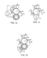
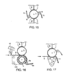
- Figs. 10-17 illustrate other configurations, equally as useful as those thus far described, that employ a pressure head 8 fed by an extruder or other source of pressurized molten polymer resin to both introduce the molten resin that will form the molded fastener product and to apply the pressure necessary to force the resin into the fastener-shaped mold cavities.
- a pressure head 8 fed by an extruder or other source of pressurized molten polymer resin to both introduce the molten resin that will form the molded fastener product and to apply the pressure necessary to force the resin into the fastener-shaped mold cavities.
- other components of the systems that employ a pressure head 8 are essentially the same as those employing a pressure roll 2.
- These additional figures show that the novel features described with reference to a system with a pressure roll apply equally as well to a system with the pressure head 8.
- Pressure head 8 in Figs. 10-17 comprises an extruder nozzle assembly fed by an extruder (not shown). In nozzle throat 8a a sheet form flow of polymer is produced, which is applied to the mold roll 1. Shoe surfaces 8b of the nozzle assembly that conform to the curvature of the roll serve to maintain the extruder pressure against the roll and to define the gap with the mold roll that defines the thickness of the base layer of the product. Pressure head 8 thus forces the polymer into the mold cavities in mold roll 1 and forms a sheet-form film or base layer of polymer on the surface of the mold roll. As in the previous embodiments, the polymer is forced into the mold cavities to form fastener elements or the like under the high pressure of the pressure zone.
- the pressure zone forces tend to bend the mold roll away from the pressure head and are resisted by the methods described above (with, e.g. a compliant load roll 3 as in Fig. 10 or a belt system 108 as in Fig. 11 ) to maintain an even gap for forming the base layer of the fastener product.
- an arrangement for controlling the gap between mold roll 1 and pressure head 8 actively adjusts the shape and position of the pressure head relative to the mold roll. This can be done, for instance, in response to thickness sensor 13.
- the axis of mold roll 1 is supported on suitable bearings (not shown) in a load frame 60.
- An extension 60a of load frame 60 supports a head loading system 180 (e.g. a number of hydraulic cylinders or ball screw actuators arranged along the length of the pressure head).
- Molten polymer resin is supplied by a melt source or extruder 61 to head 8 under pressure.
- Head loading system 180 loads head 8, by shafts 62, against mold roll 1 through a film of molten resin, thereby maintaining a controllably constant gap between mold roll 1 and head 8 for forming the base layer of the fastener product 5.
- other means of bending pressure head 8 include a number of tie bolts between the molding head and frame 60, arranged along the length of the pressure head, that are axially adjusted either by rotating a threaded member or by controlled thermal expansion (i.e. changing the net length of the tie bolts by changing their temperature). Adjusting the lengths of individual tie bolts induces bending moments in pressure head 8 that causes its curved surface 182 to also bend along its length to conform to the curvature of the mold roll.
- mold roll 1 Under some circumstances it is desirable for mold roll 1 to be slightly elastically bent away from pressure head 8 (or pressure roll 2) by pressure zone forces to increase the axial compression between the stacked mold plates that form the mold roll in the vicinity of the high pressure zone. This can reduce the tendency of the molten resin to form flash between the mold plates. In these instances it is advantageous to have some intentional bending of the mold roll away from the pressure source, and to force the pressure mechanism (e.g., pressure head 8 or pressure roll 2) to follow that curvature in order to maintain the uniformity of the gap and of the product.
- pressure mechanism e.g., pressure head 8 or pressure roll 2
- the load system 180 comprised of several loading rods 62 distributed along the length of the pressure head, forces head 8 toward mold roll 1 near its midspan to compensate for the curvature of the mold roll.
- Rods 62 are individually controlled by a control system to locally force pressure head 8 toward or away from mold roll 1 to maintain the desired gap. This technique is particularly useful to mold extremely wide widths of product by compensating for the increased bending of relatively longer rolls subjected to higher overall mold pressure forces.
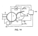
- controller 182 controls the relative positions of load roll 3 and pressure head 8 with respect to mold roll 1. Displacement transducers 184 and 186 and thickness sensor 13 provide feedback. In the embodiment shown, controller 182 controls force F 2 which loads frame 188, to which both mold roll 1 and load roll 3 are mounted, toward head 8. In addition, controller 182 controls force F 1 which forces load roll 3 against mold roll 1.
- a particularly advantageous embodiment employs two relatively stiff pressure heads 8 supplying molten resin to two pressure zones on opposite sides of a single mold roll 1. This produces two continuous streams of product 5 and 5' that are peeled from mold roll 1 by take-off rolls 6 and 6', respectively. For the reasons already described, extremely wide widths of a thin, even product are thus moldable, due to the balance of forces acting on relatively long mold roll 1.
- Figs. 18-20 illustrate some of the web base thickness profiles that can be maintained by the apparatus and method of the present invention, shown in cross-section across a portion of the length of the mold roll.
- fastener product 5 has a base web 200 and multiple upstanding fastener elements 202. Maintaining the thickness of the mold gap that forms base web 200 along its length produces a product 5 with a base web 200 of generally consistent thickness t.
- tapered regions 204 are provided in the predetermined profile of base web 200.
- grooves 206 or other indentations are formed in base web 200, as shown in Fig. 20 .
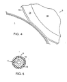
- a compliant pressure roll 2' is employed to protect surface features on the surface of a sheet material 210 introduced to the molding nip between pressure roll 2' and mold roll 1. These surface features would tend to be damaged by being passed through a nip formed by two non-conformable rolls. Hard surface features can also damage non-conformable roll surfaces.
- This arrangement is particularly useful, according to the invention, for continuous molding of fastener elements on one side of a sandpaper product having surface features consisting of grains of sand or other abrasive particles adhered to one broad surface of the paper.
- Fig. 22 looking in the direction of the flow of material through the mold nip between compliant pressure roll 2' and mold roll 1, illustrates the deformation of the surface of the pressure roll in the vicinity of abrasive grains 212 as a sandpaper product 214 is passed through the nip.
- Abrasive grains 212 are quite small in most commercial sandpapers, which have grades from 30 to over 600 for fine polishing applications.
- the compliant surface of pressure roll 2' preferably of an elastomeric material of 60 to 70 durometer for use with a medium-grit sandpaper, conforms to encapsulate the grains 212 and distribute pressure around the grains.
- the resulting abrasive product is "in situ laminated" to fastener elements such as hooks for hook to loop fastening.
- fastener elements such as hooks for hook to loop fastening.
- the resin of the base web is laminated to the back of the sandpaper to provide a means for fastening the sandpaper to a sanding block or other sanding device.
Landscapes
- Engineering & Computer Science (AREA)
- Mechanical Engineering (AREA)
- Manufacturing & Machinery (AREA)
- Moulds For Moulding Plastics Or The Like (AREA)
- Slide Fasteners, Snap Fasteners, And Hook Fasteners (AREA)
- Casting Or Compression Moulding Of Plastics Or The Like (AREA)
- Extrusion Moulding Of Plastics Or The Like (AREA)
Claims (10)
- Verfahren zum kontinuierlichen Formen von Befestigerelementen (202) auf einer Breitseite eines Bogenerzeugnisses gegenüberliegend bzw. entgegengesetzt zu einer weiteren Breitseite mit Oberflächenstrukturen bzw. -merkmalen (212), umfassend
ein Bereitstellen einer Vorrichtung, die beinhaltet:eine zylindrische Formungswalze (1), die um eine Achse drehbar ist und Befestigerelementformungshohlräume (102) an einer Umfangsoberfläche hiervon festlegt,eine zylindrische Druckwalze (2') mit einer elastischen, nachgiebigen Oberfläche, die angeordnet ist, um mit der Formungswalze (1) an einem Walzenspalt in Eingriff zu treten und einen Formungsspalt an dem Walzenspalt zum Bilden der Grundbahn zu bilden, wobei die Druckwalze derart aufgebaut ist, dass sie einen Betriebsdruck einsetzt, um Harz in die Hohlräume zu drücken, undeine Extruderdüse (4) zum Einleiten von geschmolzenem Harz (100) in den Walzenspalt,ein Hindurchleiten eines Bogenerzeugnisses (210) mit Oberflächenstrukturen (212) durch den Walzenspalt mit dem geschmolzenen Harz derart, dass die elastische Oberfläche der Druckwalze in der Umgebung der Oberflächenstrukturen nachgibt, um die Oberflächenstrukturen des Erzeugnisses zu schützen, wenn diese durch den Walzenspalt hindurchlaufen,
wodurch Befestigerelemente integral mit einer Grundbahn (200) auf einer Breitseite des Bogenerzeugnisses gebildet werden. - Verfahren nach Anspruch 1 zum Bilden eines abrasiven Bogenerzeugnisses mit geformten Befestigerelementen (202) auf einer Seite und abrasiven Teilchen (212) auf der anderen Seite, wobei die Oberflächenstrukturen abrasive Teilchen umfassen.
- Verfahren nach Anspruch 1, wobei die Hohlräume (102) die Form von funktionellen Befestigerelementen (202) festlegen.
- Verfahren nach Anspruch 1, wobei die Formungshohlräume (102) wenigstens teilweise die Form von Schlingen- oder Fasereingriffshakenelementen (202) festlegen und jedes Element einen Fuß- oder Stielabschnitt und wenigstens einen Kopfabschnitt aufweist, der zu einer Seite des Fuß- oder Stielabschnittes hin vorsteht.
- Verfahren nach Anspruch 1, wobei die Befestigerelemente (202) Pilzform oder stielförmige Vorformen aufweisen, die anschließend bearbeitet werden, um Pilze oder andere Elemente mit flachen oder abgerundeten Köpfen zu bilden.
- Verfahren nach Anspruch 1, wobei die Oberflächenstrukturen (212) erhöhte oder vertiefte Abschnitte des Bogenerzeugnisses umfassen:
- Verfahren nach Anspruch 1 wobei die nachgiebige Oberfläche der Druckwalze (2') aus einem elastomeren Material besteht.
- Verfahren nach Anspruch 7 wobei das elastomere Material eine Durometerhärte von 60 bis 70 aufweist.
- Verfahren nach Anspruch 1, wobei die Oberflächenstrukturen eine Ziertextur umfassen.
- Verfahren nach Anspruch 1, wobei das Bogenerzeugnis eine Wandbekleidung bzw. Tapete umfasst.
Applications Claiming Priority (3)
| Application Number | Priority Date | Filing Date | Title |
|---|---|---|---|
| US08/838,279 US5945131A (en) | 1997-04-16 | 1997-04-16 | Continuous molding of fastener products and the like and products produced thereby |
| US838279 | 1997-04-16 | ||
| EP98915631A EP1009606B1 (de) | 1997-04-16 | 1998-04-16 | Kontinuierliches formen von befestigungsprodukten und dergleichen sowie auf diese weise hergestellte produkte |
Related Parent Applications (1)
| Application Number | Title | Priority Date | Filing Date |
|---|---|---|---|
| EP98915631A Division EP1009606B1 (de) | 1997-04-16 | 1998-04-16 | Kontinuierliches formen von befestigungsprodukten und dergleichen sowie auf diese weise hergestellte produkte |
Publications (2)
| Publication Number | Publication Date |
|---|---|
| EP1535713A1 EP1535713A1 (de) | 2005-06-01 |
| EP1535713B1 true EP1535713B1 (de) | 2008-02-27 |
Family
ID=25276716
Family Applications (2)
| Application Number | Title | Priority Date | Filing Date |
|---|---|---|---|
| EP98915631A Expired - Lifetime EP1009606B1 (de) | 1997-04-16 | 1998-04-16 | Kontinuierliches formen von befestigungsprodukten und dergleichen sowie auf diese weise hergestellte produkte |
| EP05000856A Expired - Lifetime EP1535713B1 (de) | 1997-04-16 | 1998-04-16 | Kontinuierliches Formen von Befestigungsprodukten und dergleichen sowie auf diese Weise hergestellte Produkte |
Family Applications Before (1)
| Application Number | Title | Priority Date | Filing Date |
|---|---|---|---|
| EP98915631A Expired - Lifetime EP1009606B1 (de) | 1997-04-16 | 1998-04-16 | Kontinuierliches formen von befestigungsprodukten und dergleichen sowie auf diese weise hergestellte produkte |
Country Status (8)
| Country | Link |
|---|---|
| US (5) | US5945131A (de) |
| EP (2) | EP1009606B1 (de) |
| JP (1) | JP2002514141A (de) |
| CN (2) | CN1108911C (de) |
| AU (1) | AU6976798A (de) |
| DE (2) | DE69839199T2 (de) |
| ES (2) | ES2302082T3 (de) |
| WO (1) | WO1998046406A1 (de) |
Families Citing this family (80)
| Publication number | Priority date | Publication date | Assignee | Title |
|---|---|---|---|---|
| US5900350A (en) * | 1996-06-06 | 1999-05-04 | Velcro Industries B.V. | Molding methods, molds and products |
| US5945131A (en) * | 1997-04-16 | 1999-08-31 | Velcro Industries B.V. | Continuous molding of fastener products and the like and products produced thereby |
| US6296733B1 (en) * | 1998-12-01 | 2001-10-02 | Lear Corporation | Floor mats and method of making same |
| DE19906008A1 (de) * | 1999-02-15 | 2000-08-17 | Binder Kletten Haftverschlus S | Verfahren und Vorrichtung zur Herstellung von Haftverschlußteilen aus strahlengehärteten Kunststoffen |
| US6592800B1 (en) * | 1999-10-04 | 2003-07-15 | 3M Innovative Properties Company | Apparatus and method for making a mechanical fastener |
| US20060210762A1 (en) * | 2005-03-17 | 2006-09-21 | Tachauer Ernesto S | Rigid subtrates having molded projections, and methods of making the same |
| CN1229216C (zh) | 2000-03-14 | 2005-11-30 | 维尔克鲁工业公司 | 形成连接物制品的方法 |
| US20030129411A1 (en) * | 2000-06-10 | 2003-07-10 | Hideaki Saito | Adhesive for resin roll assembly and resin roll |
| US8678807B2 (en) * | 2000-10-24 | 2014-03-25 | Velcro Industries B.V. | Molding apparatus and related methods |
| US7785095B2 (en) * | 2001-03-14 | 2010-08-31 | Velcro Industries B.V. | Molding apparatus and related methods |
| US20020142143A1 (en) * | 2001-03-29 | 2002-10-03 | Fort James Corporation | Laser engraved embossing roll |
| DE10123205A1 (de) * | 2001-05-12 | 2002-11-28 | Binder Gottlieb Gmbh & Co | Verfahren zur Herstellung eines Haftverschlußteils |
| DE10123206A1 (de) * | 2001-05-12 | 2002-11-28 | Binder Gottlieb Gmbh & Co | Verfahren zum Herstellen eines Haftverschlußteils |
| EP1404501B1 (de) * | 2001-06-05 | 2012-08-01 | Mikro Systems Inc. | Verfahren und guss-system zur herstellung dreidimensionaler vorrichtungen |
| US7785098B1 (en) | 2001-06-05 | 2010-08-31 | Mikro Systems, Inc. | Systems for large area micro mechanical systems |
| US20030045412A1 (en) * | 2001-07-13 | 2003-03-06 | Schulz Galyn A. | Laser engraved embossing roll with wear-resistant coatings and method of making them |
| US6843944B2 (en) * | 2001-11-01 | 2005-01-18 | 3M Innovative Properties Company | Apparatus and method for capping wide web reclosable fasteners |
| US6652273B2 (en) * | 2002-01-14 | 2003-11-25 | The Procter & Gamble Company | Apparatus and method for controlling the temperature of manufacturing equipment |
| GB2390560A (en) * | 2002-07-09 | 2004-01-14 | Ykk Europ Ltd | Support disc for sanding apparatus |
| US6814912B2 (en) * | 2002-12-17 | 2004-11-09 | 3M Innovative Properties Company | Heat treated high density structures |
| US7132144B2 (en) | 2003-02-28 | 2006-11-07 | Velcro Industries B.V. | Fastener tapes |
| US7225510B2 (en) * | 2003-03-05 | 2007-06-05 | Velern Industries B.V. | Fastener product |
| US7238314B2 (en) * | 2003-03-13 | 2007-07-03 | 3M Innovative Properties Company | Polymer transfer apparatus, methods, and composite webs |
| JP2005014522A (ja) * | 2003-06-27 | 2005-01-20 | Toshiba Mach Co Ltd | フィルム・シート成形装置 |
| SE526725C2 (sv) * | 2003-09-17 | 2005-11-01 | Acreo Ab | Förfarande och anordning för tillverkning av elektriska komponenter |
| US7297226B2 (en) | 2004-02-11 | 2007-11-20 | Georgia-Pacific Consumer Products Lp | Apparatus and method for degrading a web in the machine direction while preserving cross-machine direction strength |
| US7303711B2 (en) * | 2004-02-24 | 2007-12-04 | Velcro Industries B.V. | Fastener products |
| US7438847B2 (en) * | 2004-03-18 | 2008-10-21 | Velcro Industries B.V. | Delivering resin for forming fastener products |
| EP1725385B1 (de) * | 2004-03-18 | 2007-09-19 | Velcro Industries B.V. (NL) | Übertragung von harz zum formen von befestigungselementen |
| DE102004021423A1 (de) * | 2004-04-30 | 2005-12-01 | Siemens Ag | Verfahren und Einrichtung zur Ermittlung der Leistungsfähigkeit eines Wärmetauschers |
| TW200618999A (en) * | 2004-12-08 | 2006-06-16 | Spring Rich Ltd | Method for manufacturing hook fasteners |
| EP1669001A1 (de) * | 2004-12-10 | 2006-06-14 | 3M Innovative Properties Company | Bandförmiger männlicher Teil eines Klettverschlusses, davon abgetrennter Streifen und daraus gebildeter Befestigungsstreifen |
| ATE489015T1 (de) | 2005-03-11 | 2010-12-15 | 3M Innovative Properties Co | Verfahren zur herstellung von verschlüssen |
| US7601284B2 (en) * | 2005-04-06 | 2009-10-13 | Velcro Industries B.V. | Molding fastener elements on folded substrate |
| WO2006121695A1 (en) * | 2005-05-05 | 2006-11-16 | Velcro Industries B.V. | Molding fastener stems onto substrate |
| JP5005909B2 (ja) * | 2005-11-18 | 2012-08-22 | 勝行 戸津 | ねじ具の緩み止め締結具及びその製造方法 |
| JP4870522B2 (ja) * | 2005-11-22 | 2012-02-08 | 富士フイルム株式会社 | 熱可塑性樹脂フィルムの製造方法 |
| GB2437540B (en) | 2006-04-24 | 2010-12-01 | Uponor Innovation Ab | Fastening of pipes |
| US20070261224A1 (en) * | 2006-05-11 | 2007-11-15 | Dow Global Technologies Inc. | Methods and articles in having a fringed microprotrusion surface structure |
| US7636988B2 (en) * | 2006-09-11 | 2009-12-29 | 3M Innovative Properties Company | Methods for making fasteners |
| EP1952962A1 (de) * | 2007-01-31 | 2008-08-06 | Apparecchiature Macchine Utensili S.p.A. | Verfahren und Fertigungsstrasse zur kontinuierlichen Herstellung von Folien aus thermoplastischem Kunststoff |
| WO2008154303A1 (en) | 2007-06-07 | 2008-12-18 | Velcro Industries B.V. | Needling loops into carrier sheets |
| WO2008154300A1 (en) | 2007-06-07 | 2008-12-18 | Velcro Industries B.V. | Anchoring loops of fibers needled into a carrier sheet |
| CN101896337B (zh) * | 2007-10-12 | 2013-10-30 | 流体科技公司 | 用于生产颗粒和图案化膜的系统和方法 |
| JP5324777B2 (ja) * | 2007-12-07 | 2013-10-23 | 住友化学株式会社 | 押出樹脂板の製造方法 |
| NO330660B1 (no) * | 2008-03-12 | 2011-06-06 | Tore Eide | Sensorenhet og fremgangsmate for overvaking av tilstanden til surringsmateriell. |
| US9315663B2 (en) | 2008-09-26 | 2016-04-19 | Mikro Systems, Inc. | Systems, devices, and/or methods for manufacturing castings |
| US20110081489A1 (en) * | 2009-10-01 | 2011-04-07 | Reid Brian P | Method of forming a display blank having an encapsulated fragrance |
| US8522406B2 (en) | 2009-11-10 | 2013-09-03 | Velcro Industries B.V. | Releasable fastening along a bead |
| US9138957B2 (en) | 2010-06-21 | 2015-09-22 | 3M Innovative Properties Company | Slit hook strips and laminates and articles containing the same |
| US9138031B2 (en) | 2011-02-16 | 2015-09-22 | 3M Innovative Properties Company | Method of making a mechanical fastening strip and reticulated mechanical fastening strip therefrom |
| CN102354009B (zh) * | 2011-07-02 | 2013-05-08 | 浙江道明光学股份有限公司 | 用圆筒模具生产具有微棱镜阵列结构反光膜的设备 |
| US9085104B2 (en) * | 2011-07-20 | 2015-07-21 | Nordson Corporation | Sculpted extrusion die |
| US8813824B2 (en) | 2011-12-06 | 2014-08-26 | Mikro Systems, Inc. | Systems, devices, and/or methods for producing holes |
| US9296146B1 (en) | 2012-03-09 | 2016-03-29 | Rambus Delaware Llc | Extrusion-to-sheet production line and method |
| US9399333B2 (en) * | 2012-04-18 | 2016-07-26 | Velcro BVBA | Forming laminated touch fasteners |
| US8889243B2 (en) | 2012-08-16 | 2014-11-18 | 3M Innovative Properties Company | Mechanical fastening nets and methods of making the same |
| EP2724864B1 (de) * | 2012-10-24 | 2018-12-26 | Heidelberger Druckmaschinen AG | Verfahren und Vorrichtung zur Erzeugung und Übertragung diffraktiver Mikrostrukturen auf einen Bedruckstoff |
| US9295590B2 (en) * | 2012-11-27 | 2016-03-29 | The Procter & Gamble Company | Method and apparatus for applying an elastic material to a moving substrate in a curved path |
| US20160193757A1 (en) * | 2013-09-26 | 2016-07-07 | Ykk Corporation | Surface Fastener Molding Apparatus and its Operational Method, and a Method for Producing a Surface Fastener |
| US9776353B2 (en) * | 2013-10-02 | 2017-10-03 | Velcro BVBA | Longitudinal bead molding |
| TR201810122T4 (tr) * | 2014-02-18 | 2018-08-27 | Boato Int S P A A Socio Unico | Önceden hazirlanmiş su geçi̇rmez bi̇tüm karişimi membranlarini süsleme aparati ve söz konusu önceden hazirlanmiş su geçi̇rmez membranlarin üreti̇mi̇ i̇çi̇n i̇lgi̇li̇ tesi̇s. |
| FR3020680B1 (fr) | 2014-05-02 | 2017-11-24 | Michelin & Cie | Systeme d'evaluation de l'etat d'un pneumatique |
| AR105076A1 (es) * | 2015-06-30 | 2017-09-06 | Goodyear Tire & Rubber | Aparato para formar una tira elastomérica |
| WO2017187103A1 (fr) | 2016-04-29 | 2017-11-02 | Aplix | Appareil de moulage pour la formation d'un dispositif de retenue |
| JP6710656B2 (ja) * | 2017-06-02 | 2020-06-17 | 芝浦機械株式会社 | 薄膜部材成形装置および薄膜部材の成形方法 |
| JP6311054B1 (ja) | 2017-07-20 | 2018-04-11 | 東芝機械株式会社 | 両面転写式シート・フィルム成形ロール装置、両面転写式シート・フィルム成形方法 |
| US11806910B2 (en) * | 2017-10-16 | 2023-11-07 | Compagnie Generale Des Etablissements Michelin | Production of a layered semi-finished product for use in tire production |
| US11110632B2 (en) * | 2017-10-30 | 2021-09-07 | Velcro Ip Holdings Llc | Roll-molding |
| US10556369B2 (en) | 2017-10-30 | 2020-02-11 | Velcro BVBA | Modular molding assembly |
| US10894345B2 (en) | 2017-10-30 | 2021-01-19 | Velcro BVBA | Linear actuator leverage |
| EP3727786B1 (de) | 2017-12-21 | 2022-02-02 | Velcro IP Holdings LLC | Formvorrichtung und verfahren zur herstellung von kontinuierlichen strukturen |
| FR3086198B1 (fr) * | 2018-09-20 | 2022-01-28 | Michelin & Cie | Machine de coextrusion pour melanges elastomeriques |
| US11161283B2 (en) * | 2018-12-20 | 2021-11-02 | Velcro Ip Holdings Llc | Molding fastener products |
| US10709022B1 (en) | 2019-04-19 | 2020-07-07 | Gentherm Incorporated | Milling of flex foil with two conductive layers from both sides |
| DE102019126895A1 (de) * | 2019-10-07 | 2021-04-08 | KraussMaffei Extrusion GmbH | Walzvorrichtung mit Hohlzylinder |
| CN111185603B (zh) * | 2020-04-03 | 2024-10-22 | 郑州机械研究所有限公司 | 基于载荷补偿的等离子旋转电极雾化制粉设备母材驱动机构 |
| CN114833254B (zh) * | 2022-05-11 | 2023-07-21 | 南京林业大学 | 一种电磁辅助滚弯成形方法及其成形装置 |
| US11889903B1 (en) * | 2023-03-20 | 2024-02-06 | Velcro Ip Holdings Llc | Male touch fastener elements |
| CN117817927B (zh) * | 2024-03-01 | 2024-09-10 | 山东义沃包装科技有限公司 | 具有热交换的膜制品加工一次流延后预加热装置 |
Family Cites Families (41)
| Publication number | Priority date | Publication date | Assignee | Title |
|---|---|---|---|---|
| US1988787A (en) * | 1933-05-23 | 1935-01-22 | Hood Rubber Co Inc | Manufacture of embossed sheet material and roll for producing same |
| US2897538A (en) * | 1956-11-15 | 1959-08-04 | Commercial Plastics Ltd | Means for bending the rolls of rolling machines |
| US3089191A (en) * | 1961-06-13 | 1963-05-14 | American Pipe & Constr Co | Product method and apparatus for making a hobbed-surfaced sheet material |
| NL299751A (de) * | 1962-10-26 | |||
| US3312583A (en) * | 1963-10-02 | 1967-04-04 | James J Rochlis | Apertured and staggered molded pile product |
| US3363663A (en) | 1965-06-07 | 1968-01-16 | United States Gypsum Co | Combustion chamber burner and a method for its operation |
| US3353663A (en) * | 1966-02-10 | 1967-11-21 | Minnesota Mining & Mfg | Adherent fasteners |
| US3594863A (en) * | 1969-07-10 | 1971-07-27 | American Velcro Inc | Apparatus for molding plastic shapes in molding recesses formed in a moving endless belt |
| US3594865A (en) * | 1969-07-10 | 1971-07-27 | American Velcro Inc | Apparatus for molding plastic shapes in molding recesses formed in moving endless wire dies |
| US3756760A (en) * | 1971-11-08 | 1973-09-04 | Hallmark Cards | Finishing roll for extruded plastic sheet |
| US3752619A (en) * | 1971-11-11 | 1973-08-14 | American Velcro Inc | Production of a continuous molded plastic strip |
| US3956056A (en) * | 1972-11-20 | 1976-05-11 | Uniroyal Inc. | Fabric coating by extrusion die-calendering apparatus and method |
| GB1472405A (en) | 1973-09-27 | 1977-05-04 | Ici Ltd | Production of pile surfaced materials |
| BE840727A (fr) * | 1975-05-24 | 1976-08-02 | Calandre a cylindres multiples | |
| SE423692B (sv) * | 1976-02-20 | 1982-05-24 | Textron Inc | Sett och anordning for formning av en serie hektelement for ett blixlas |
| FI64902C (fi) * | 1976-03-30 | 1984-02-10 | Wiik & Hoeglund | Foerfarande foer kompensering av valsboejningen i en kalander |
| CH601686A5 (de) * | 1976-11-30 | 1978-07-14 | Escher Wyss Ag | |
| CH662837A5 (de) * | 1983-02-10 | 1987-10-30 | Escher Wyss Ag | Kalander zur druck- und waermebehandlung von warenbahnen. |
| US4775310A (en) * | 1984-04-16 | 1988-10-04 | Velcro Industries B.V. | Apparatus for making a separable fastener |
| US4794028A (en) * | 1984-04-16 | 1988-12-27 | Velcro Industries B.V. | Method for continuously producing a multi-hook fastner member and product of the method |
| GB2161105B (en) * | 1984-07-04 | 1988-06-15 | Fred Whitehead | Calendar or roll assembly |
| US4609581A (en) * | 1985-04-15 | 1986-09-02 | Minnesota Mining And Manufacturing Company | Coated abrasive sheet material with loop attachment means |
| EP0322127B1 (de) * | 1987-12-04 | 1994-02-02 | Canon Kabushiki Kaisha | Rotierendes Bauteil für Fixiergerät und Fixiergerät hierfür |
| US5254194A (en) * | 1988-05-13 | 1993-10-19 | Minnesota Mining And Manufacturing Company | Coated abrasive sheet material with loop material for attachment incorporated therein |
| DE3903022C1 (de) * | 1989-02-02 | 1990-04-26 | Hermann Berstorff Maschinenbau Gmbh, 3000 Hannover, De | |
| JPH0397525A (ja) * | 1989-09-12 | 1991-04-23 | Canon Inc | 光情報記録媒体用基板の製造方法 |
| US5263840A (en) * | 1989-10-30 | 1993-11-23 | Sulzer-Escher Wyss Gmbh | Calendar for surface treatment of material webs |
| US5116563A (en) * | 1990-06-28 | 1992-05-26 | The Procter & Gamble Company | Process for producing a mechanical fastener |
| CH682893A5 (de) * | 1991-05-03 | 1993-12-15 | Escher Wyss Ag | Walze und Kunststoffolien-Giessanlage mit einer Walze. |
| US5260015A (en) * | 1991-08-16 | 1993-11-09 | Velcro Industries, B.V. | Method for making a laminated hook fastener |
| JP2756211B2 (ja) * | 1992-06-17 | 1998-05-25 | ワイケイケイ株式会社 | 両面に係合片を有する一体成形面ファスナーの製造方法及びその装置 |
| JP2744384B2 (ja) * | 1992-07-22 | 1998-04-28 | ワイケイケイ株式会社 | 裏面に裏部材を有する係合部材の製造方法及びその装置 |
| AU692828B2 (en) * | 1994-01-13 | 1998-06-18 | Minnesota Mining And Manufacturing Company | Abrasive article, method of making same, and abrading apparatus |
| US5785784A (en) * | 1994-01-13 | 1998-07-28 | Minnesota Mining And Manufacturing Company | Abrasive articles method of making same and abrading apparatus |
| US5505747A (en) * | 1994-01-13 | 1996-04-09 | Minnesota Mining And Manufacturing Company | Method of making an abrasive article |
| TW317223U (en) * | 1994-01-13 | 1997-10-01 | Minnesota Mining & Mfg | Abrasive article |
| ATE215439T1 (de) * | 1996-10-14 | 2002-04-15 | Idemitsu Petrochemical Co | Verfahren zur herstellung einer dekorfolie und vorrichtung zu seiner herstellung |
| US5755016A (en) * | 1996-12-23 | 1998-05-26 | Velcro Industries, B.V. | Hook and loop fastening and the like |
| US5945131A (en) * | 1997-04-16 | 1999-08-31 | Velcro Industries B.V. | Continuous molding of fastener products and the like and products produced thereby |
| US6013151A (en) * | 1998-05-15 | 2000-01-11 | Clopay Plastic Products Company, Inc. | High speed method of making microporous film products |
| TWI221929B (en) * | 2001-10-09 | 2004-10-11 | Fuji Electric Co Ltd | Overload current protection apparatus |
-
1997
- 1997-04-16 US US08/838,279 patent/US5945131A/en not_active Expired - Lifetime
-
1998
- 1998-04-16 CN CN98804314A patent/CN1108911C/zh not_active Expired - Fee Related
- 1998-04-16 EP EP98915631A patent/EP1009606B1/de not_active Expired - Lifetime
- 1998-04-16 JP JP54435998A patent/JP2002514141A/ja not_active Ceased
- 1998-04-16 ES ES05000856T patent/ES2302082T3/es not_active Expired - Lifetime
- 1998-04-16 AU AU69767/98A patent/AU6976798A/en not_active Abandoned
- 1998-04-16 DE DE69839199T patent/DE69839199T2/de not_active Expired - Lifetime
- 1998-04-16 WO PCT/US1998/007873 patent/WO1998046406A1/en not_active Ceased
- 1998-04-16 DE DE69828698T patent/DE69828698T2/de not_active Expired - Lifetime
- 1998-04-16 CN CNB021578435A patent/CN1308131C/zh not_active Expired - Fee Related
- 1998-04-16 EP EP05000856A patent/EP1535713B1/de not_active Expired - Lifetime
- 1998-04-16 ES ES98915631T patent/ES2236896T3/es not_active Expired - Lifetime
-
1999
- 1999-10-14 US US09/402,975 patent/US6482286B1/en not_active Expired - Fee Related
-
2002
- 2002-10-29 US US10/282,716 patent/US6660121B2/en not_active Expired - Fee Related
-
2003
- 2003-11-24 US US10/720,739 patent/US20040201124A2/en not_active Abandoned
-
2006
- 2006-10-23 US US11/584,874 patent/US20070035060A1/en not_active Abandoned
Also Published As
| Publication number | Publication date |
|---|---|
| US20030041957A1 (en) | 2003-03-06 |
| DE69839199T2 (de) | 2009-02-26 |
| EP1009606B1 (de) | 2005-01-19 |
| CN1255886A (zh) | 2000-06-07 |
| WO1998046406A1 (en) | 1998-10-22 |
| ES2236896T3 (es) | 2005-07-16 |
| US20070035060A1 (en) | 2007-02-15 |
| AU6976798A (en) | 1998-11-11 |
| ES2302082T3 (es) | 2008-07-01 |
| US6660121B2 (en) | 2003-12-09 |
| US20040130056A1 (en) | 2004-07-08 |
| US5945131A (en) | 1999-08-31 |
| JP2002514141A (ja) | 2002-05-14 |
| US20040201124A2 (en) | 2004-10-14 |
| CN1108911C (zh) | 2003-05-21 |
| CN1308131C (zh) | 2007-04-04 |
| DE69828698D1 (de) | 2005-02-24 |
| DE69828698T2 (de) | 2006-01-12 |
| CN1495010A (zh) | 2004-05-12 |
| DE69839199D1 (de) | 2008-04-10 |
| EP1535713A1 (de) | 2005-06-01 |
| US6482286B1 (en) | 2002-11-19 |
| EP1009606A1 (de) | 2000-06-21 |
| EP1009606A4 (de) | 2001-09-12 |
Similar Documents
| Publication | Publication Date | Title |
|---|---|---|
| US6482286B1 (en) | Continuous molding of fastener products using a pressure roll having a resilient surface | |
| JP3628965B2 (ja) | ロール形成機械 | |
| JPS5830141B2 (ja) | パ−テイクルボ−ドオ レンゾクテキニ セイゾウスルタメノソウチ | |
| EP3703924B1 (de) | Walzformung | |
| US7785095B2 (en) | Molding apparatus and related methods | |
| GB2157976A (en) | Method for calendering webs provided with a magnetic layer and calender for performing this method | |
| JP6064667B2 (ja) | 両面構造フィルムの製造方法および製造装置 | |
| US7794638B2 (en) | Transferring resin for forming fastener products | |
| US8678807B2 (en) | Molding apparatus and related methods | |
| JP2005511227A (ja) | 接着閉鎖部材の製造方法 | |
| EP3703927B1 (de) | Modulare formanordnung | |
| US6203307B1 (en) | System for finishing surface of a web of paper having an improved continuous finishing belt | |
| JP2013203000A (ja) | 微細構造転写フィルムの製造方法および製造装置 | |
| US12128661B2 (en) | Micro embossing | |
| JP2023547013A (ja) | ファスナー部品 | |
| JP2004143609A (ja) | 紙のカレンダ処理装置及び紙のカレンダ処理方法 | |
| US6007921A (en) | Continuous finishing belt capable of finishing surface of a web of paper | |
| JP6085193B2 (ja) | 微細構造フィルムの製造方法および製造装置 | |
| KR100337429B1 (ko) | 직기의마찰로울러용고무테이프의성형방법 | |
| JPH06182796A (ja) | 箔材料の連続積層方法と装置 | |
| JP2002283376A (ja) | ゴムシートの成形方法及びその装置 | |
| JPH071557A (ja) | 合成樹脂シ−トの押出成形方法 |
Legal Events
| Date | Code | Title | Description |
|---|---|---|---|
| PUAI | Public reference made under article 153(3) epc to a published international application that has entered the european phase |
Free format text: ORIGINAL CODE: 0009012 |
|
| AC | Divisional application: reference to earlier application |
Ref document number: 1009606 Country of ref document: EP Kind code of ref document: P |
|
| AK | Designated contracting states |
Kind code of ref document: A1 Designated state(s): DE ES FR GB IT SE |
|
| 17P | Request for examination filed |
Effective date: 20051027 |
|
| AKX | Designation fees paid |
Designated state(s): DE ES GB |
|
| GRAP | Despatch of communication of intention to grant a patent |
Free format text: ORIGINAL CODE: EPIDOSNIGR1 |
|
| GRAS | Grant fee paid |
Free format text: ORIGINAL CODE: EPIDOSNIGR3 |
|
| GRAA | (expected) grant |
Free format text: ORIGINAL CODE: 0009210 |
|
| RIN1 | Information on inventor provided before grant (corrected) |
Inventor name: NEUMANN, J., SCOTT Inventor name: JENS, STEPHEN, C. Inventor name: FORMATO, RICHARD, M. Inventor name: KINGSFORD, HOWARD, A. Inventor name: HARVEY, ANDREW, C. |
|
| AC | Divisional application: reference to earlier application |
Ref document number: 1009606 Country of ref document: EP Kind code of ref document: P |
|
| AK | Designated contracting states |
Kind code of ref document: B1 Designated state(s): DE ES GB |
|
| REG | Reference to a national code |
Ref country code: GB Ref legal event code: FG4D |
|
| REF | Corresponds to: |
Ref document number: 69839199 Country of ref document: DE Date of ref document: 20080410 Kind code of ref document: P |
|
| REG | Reference to a national code |
Ref country code: ES Ref legal event code: FG2A Ref document number: 2302082 Country of ref document: ES Kind code of ref document: T3 |
|
| PGFP | Annual fee paid to national office [announced via postgrant information from national office to epo] |
Ref country code: ES Payment date: 20080428 Year of fee payment: 11 |
|
| PGFP | Annual fee paid to national office [announced via postgrant information from national office to epo] |
Ref country code: GB Payment date: 20080429 Year of fee payment: 11 |
|
| PLBE | No opposition filed within time limit |
Free format text: ORIGINAL CODE: 0009261 |
|
| STAA | Information on the status of an ep patent application or granted ep patent |
Free format text: STATUS: NO OPPOSITION FILED WITHIN TIME LIMIT |
|
| 26N | No opposition filed |
Effective date: 20081128 |
|
| GBPC | Gb: european patent ceased through non-payment of renewal fee |
Effective date: 20090416 |
|
| PG25 | Lapsed in a contracting state [announced via postgrant information from national office to epo] |
Ref country code: GB Free format text: LAPSE BECAUSE OF NON-PAYMENT OF DUE FEES Effective date: 20090416 |
|
| REG | Reference to a national code |
Ref country code: ES Ref legal event code: FD2A Effective date: 20090417 |
|
| PG25 | Lapsed in a contracting state [announced via postgrant information from national office to epo] |
Ref country code: ES Free format text: LAPSE BECAUSE OF NON-PAYMENT OF DUE FEES Effective date: 20090417 |
|
| PGFP | Annual fee paid to national office [announced via postgrant information from national office to epo] |
Ref country code: DE Payment date: 20110427 Year of fee payment: 14 |
|
| REG | Reference to a national code |
Ref country code: DE Ref legal event code: R119 Ref document number: 69839199 Country of ref document: DE Effective date: 20121101 |
|
| PG25 | Lapsed in a contracting state [announced via postgrant information from national office to epo] |
Ref country code: DE Free format text: LAPSE BECAUSE OF NON-PAYMENT OF DUE FEES Effective date: 20121101 |