EP3703927B1 - Modulare formanordnung - Google Patents
Modulare formanordnung Download PDFInfo
- Publication number
- EP3703927B1 EP3703927B1 EP18793601.8A EP18793601A EP3703927B1 EP 3703927 B1 EP3703927 B1 EP 3703927B1 EP 18793601 A EP18793601 A EP 18793601A EP 3703927 B1 EP3703927 B1 EP 3703927B1
- Authority
- EP
- European Patent Office
- Prior art keywords
- molding
- resin
- roll
- pressure
- reaction surface
- Prior art date
- Legal status (The legal status is an assumption and is not a legal conclusion. Google has not performed a legal analysis and makes no representation as to the accuracy of the status listed.)
- Active
Links
Images


Classifications
-
- B—PERFORMING OPERATIONS; TRANSPORTING
- B29—WORKING OF PLASTICS; WORKING OF SUBSTANCES IN A PLASTIC STATE IN GENERAL
- B29C—SHAPING OR JOINING OF PLASTICS; SHAPING OF MATERIAL IN A PLASTIC STATE, NOT OTHERWISE PROVIDED FOR; AFTER-TREATMENT OF THE SHAPED PRODUCTS, e.g. REPAIRING
- B29C43/00—Compression moulding, i.e. applying external pressure to flow the moulding material; Apparatus therefor
- B29C43/32—Component parts, details or accessories; Auxiliary operations
- B29C43/44—Compression means for making articles of indefinite length
- B29C43/46—Rollers
-
- B—PERFORMING OPERATIONS; TRANSPORTING
- B29—WORKING OF PLASTICS; WORKING OF SUBSTANCES IN A PLASTIC STATE IN GENERAL
- B29C—SHAPING OR JOINING OF PLASTICS; SHAPING OF MATERIAL IN A PLASTIC STATE, NOT OTHERWISE PROVIDED FOR; AFTER-TREATMENT OF THE SHAPED PRODUCTS, e.g. REPAIRING
- B29C43/00—Compression moulding, i.e. applying external pressure to flow the moulding material; Apparatus therefor
- B29C43/22—Compression moulding, i.e. applying external pressure to flow the moulding material; Apparatus therefor of articles of indefinite length
- B29C43/222—Compression moulding, i.e. applying external pressure to flow the moulding material; Apparatus therefor of articles of indefinite length characterised by the shape of the surface
-
- B—PERFORMING OPERATIONS; TRANSPORTING
- B29—WORKING OF PLASTICS; WORKING OF SUBSTANCES IN A PLASTIC STATE IN GENERAL
- B29C—SHAPING OR JOINING OF PLASTICS; SHAPING OF MATERIAL IN A PLASTIC STATE, NOT OTHERWISE PROVIDED FOR; AFTER-TREATMENT OF THE SHAPED PRODUCTS, e.g. REPAIRING
- B29C43/00—Compression moulding, i.e. applying external pressure to flow the moulding material; Apparatus therefor
- B29C43/22—Compression moulding, i.e. applying external pressure to flow the moulding material; Apparatus therefor of articles of indefinite length
- B29C43/24—Calendering
- B29C43/245—Adjusting calender parameters, e.g. bank quantity
-
- B—PERFORMING OPERATIONS; TRANSPORTING
- B29—WORKING OF PLASTICS; WORKING OF SUBSTANCES IN A PLASTIC STATE IN GENERAL
- B29C—SHAPING OR JOINING OF PLASTICS; SHAPING OF MATERIAL IN A PLASTIC STATE, NOT OTHERWISE PROVIDED FOR; AFTER-TREATMENT OF THE SHAPED PRODUCTS, e.g. REPAIRING
- B29C43/00—Compression moulding, i.e. applying external pressure to flow the moulding material; Apparatus therefor
- B29C43/22—Compression moulding, i.e. applying external pressure to flow the moulding material; Apparatus therefor of articles of indefinite length
- B29C43/28—Compression moulding, i.e. applying external pressure to flow the moulding material; Apparatus therefor of articles of indefinite length incorporating preformed parts or layers, e.g. compression moulding around inserts or for coating articles
-
- B—PERFORMING OPERATIONS; TRANSPORTING
- B29—WORKING OF PLASTICS; WORKING OF SUBSTANCES IN A PLASTIC STATE IN GENERAL
- B29C—SHAPING OR JOINING OF PLASTICS; SHAPING OF MATERIAL IN A PLASTIC STATE, NOT OTHERWISE PROVIDED FOR; AFTER-TREATMENT OF THE SHAPED PRODUCTS, e.g. REPAIRING
- B29C43/00—Compression moulding, i.e. applying external pressure to flow the moulding material; Apparatus therefor
- B29C43/32—Component parts, details or accessories; Auxiliary operations
- B29C43/50—Removing moulded articles
-
- B—PERFORMING OPERATIONS; TRANSPORTING
- B29—WORKING OF PLASTICS; WORKING OF SUBSTANCES IN A PLASTIC STATE IN GENERAL
- B29C—SHAPING OR JOINING OF PLASTICS; SHAPING OF MATERIAL IN A PLASTIC STATE, NOT OTHERWISE PROVIDED FOR; AFTER-TREATMENT OF THE SHAPED PRODUCTS, e.g. REPAIRING
- B29C48/00—Extrusion moulding, i.e. expressing the moulding material through a die or nozzle which imparts the desired form; Apparatus therefor
- B29C48/001—Combinations of extrusion moulding with other shaping operations
- B29C48/0011—Combinations of extrusion moulding with other shaping operations combined with compression moulding
-
- B—PERFORMING OPERATIONS; TRANSPORTING
- B29—WORKING OF PLASTICS; WORKING OF SUBSTANCES IN A PLASTIC STATE IN GENERAL
- B29C—SHAPING OR JOINING OF PLASTICS; SHAPING OF MATERIAL IN A PLASTIC STATE, NOT OTHERWISE PROVIDED FOR; AFTER-TREATMENT OF THE SHAPED PRODUCTS, e.g. REPAIRING
- B29C48/00—Extrusion moulding, i.e. expressing the moulding material through a die or nozzle which imparts the desired form; Apparatus therefor
- B29C48/25—Component parts, details or accessories; Auxiliary operations
- B29C48/30—Extrusion nozzles or dies
- B29C48/35—Extrusion nozzles or dies with rollers
-
- B—PERFORMING OPERATIONS; TRANSPORTING
- B29—WORKING OF PLASTICS; WORKING OF SUBSTANCES IN A PLASTIC STATE IN GENERAL
- B29C—SHAPING OR JOINING OF PLASTICS; SHAPING OF MATERIAL IN A PLASTIC STATE, NOT OTHERWISE PROVIDED FOR; AFTER-TREATMENT OF THE SHAPED PRODUCTS, e.g. REPAIRING
- B29C43/00—Compression moulding, i.e. applying external pressure to flow the moulding material; Apparatus therefor
- B29C43/32—Component parts, details or accessories; Auxiliary operations
- B29C43/34—Feeding the material to the mould or the compression means
- B29C2043/3433—Feeding the material to the mould or the compression means using dispensing heads, e.g. extruders, placed over or apart from the moulds
-
- B—PERFORMING OPERATIONS; TRANSPORTING
- B29—WORKING OF PLASTICS; WORKING OF SUBSTANCES IN A PLASTIC STATE IN GENERAL
- B29C—SHAPING OR JOINING OF PLASTICS; SHAPING OF MATERIAL IN A PLASTIC STATE, NOT OTHERWISE PROVIDED FOR; AFTER-TREATMENT OF THE SHAPED PRODUCTS, e.g. REPAIRING
- B29C43/00—Compression moulding, i.e. applying external pressure to flow the moulding material; Apparatus therefor
- B29C43/32—Component parts, details or accessories; Auxiliary operations
- B29C43/44—Compression means for making articles of indefinite length
- B29C43/46—Rollers
- B29C2043/461—Rollers the rollers having specific surface features
- B29C2043/465—Rollers the rollers having specific surface features having one or more cavities, e.g. for forming distinct products
-
- B—PERFORMING OPERATIONS; TRANSPORTING
- B29—WORKING OF PLASTICS; WORKING OF SUBSTANCES IN A PLASTIC STATE IN GENERAL
- B29C—SHAPING OR JOINING OF PLASTICS; SHAPING OF MATERIAL IN A PLASTIC STATE, NOT OTHERWISE PROVIDED FOR; AFTER-TREATMENT OF THE SHAPED PRODUCTS, e.g. REPAIRING
- B29C43/00—Compression moulding, i.e. applying external pressure to flow the moulding material; Apparatus therefor
- B29C43/32—Component parts, details or accessories; Auxiliary operations
- B29C43/44—Compression means for making articles of indefinite length
- B29C43/46—Rollers
- B29C2043/467—Rollers plurality of rollers arranged in a specific manner in relation to each other
-
- B—PERFORMING OPERATIONS; TRANSPORTING
- B29—WORKING OF PLASTICS; WORKING OF SUBSTANCES IN A PLASTIC STATE IN GENERAL
- B29C—SHAPING OR JOINING OF PLASTICS; SHAPING OF MATERIAL IN A PLASTIC STATE, NOT OTHERWISE PROVIDED FOR; AFTER-TREATMENT OF THE SHAPED PRODUCTS, e.g. REPAIRING
- B29C43/00—Compression moulding, i.e. applying external pressure to flow the moulding material; Apparatus therefor
- B29C43/32—Component parts, details or accessories; Auxiliary operations
- B29C43/34—Feeding the material to the mould or the compression means
-
- B—PERFORMING OPERATIONS; TRANSPORTING
- B29—WORKING OF PLASTICS; WORKING OF SUBSTANCES IN A PLASTIC STATE IN GENERAL
- B29C—SHAPING OR JOINING OF PLASTICS; SHAPING OF MATERIAL IN A PLASTIC STATE, NOT OTHERWISE PROVIDED FOR; AFTER-TREATMENT OF THE SHAPED PRODUCTS, e.g. REPAIRING
- B29C48/00—Extrusion moulding, i.e. expressing the moulding material through a die or nozzle which imparts the desired form; Apparatus therefor
- B29C48/14—Extrusion moulding, i.e. expressing the moulding material through a die or nozzle which imparts the desired form; Apparatus therefor characterised by the particular extruding conditions, e.g. in a modified atmosphere or by using vibration
- B29C48/142—Extrusion moulding, i.e. expressing the moulding material through a die or nozzle which imparts the desired form; Apparatus therefor characterised by the particular extruding conditions, e.g. in a modified atmosphere or by using vibration using force fields, e.g. gravity or electrical fields
-
- B—PERFORMING OPERATIONS; TRANSPORTING
- B29—WORKING OF PLASTICS; WORKING OF SUBSTANCES IN A PLASTIC STATE IN GENERAL
- B29C—SHAPING OR JOINING OF PLASTICS; SHAPING OF MATERIAL IN A PLASTIC STATE, NOT OTHERWISE PROVIDED FOR; AFTER-TREATMENT OF THE SHAPED PRODUCTS, e.g. REPAIRING
- B29C48/00—Extrusion moulding, i.e. expressing the moulding material through a die or nozzle which imparts the desired form; Apparatus therefor
- B29C48/14—Extrusion moulding, i.e. expressing the moulding material through a die or nozzle which imparts the desired form; Apparatus therefor characterised by the particular extruding conditions, e.g. in a modified atmosphere or by using vibration
- B29C48/146—Extrusion moulding, i.e. expressing the moulding material through a die or nozzle which imparts the desired form; Apparatus therefor characterised by the particular extruding conditions, e.g. in a modified atmosphere or by using vibration in the die
-
- B—PERFORMING OPERATIONS; TRANSPORTING
- B29—WORKING OF PLASTICS; WORKING OF SUBSTANCES IN A PLASTIC STATE IN GENERAL
- B29L—INDEXING SCHEME ASSOCIATED WITH SUBCLASS B29C, RELATING TO PARTICULAR ARTICLES
- B29L2031/00—Other particular articles
- B29L2031/727—Fastening elements
- B29L2031/729—Hook and loop-type fasteners
Definitions
- This invention relates generally to equipment and methods for making longitudinally continuous products with limited arrays of molded projections, such as fastener elements.
- Roll-forming processes are employed to mold resin into various products, including to mold continuous flexible strips of resin with arrays of projections extending from one side of a base layer.
- the strips are formed permanently laminated to a flexible substrate, such as by running the substrate through a molding nip with molten resin, and pressing the resin into cavities of a molding roller.
- the resin can be introduced to the roller in separate streams, so as to mold spaced strips on the substrate.
- US 2004/0201124 A2 describes an apparatus that includes a cylindrical mold roll rotatable about an axis and defining small fastener element-shaped mold cavities in the surface thereof and pressure-applying means to apply operating pressure to force the resin into the cavities at a pressure zone.
- the pressure-applying means and mold roll define a mold gap therebetween for forming the base web.
- the pressure-applying means may include a pressure roll and load rolls that are loaded independently against the mold roll to maintain a constant, even gap between the mold roll and the pressure roll to produce an even thickness product.
- the molding apparatus includes a reaction surface and multiple molding modules.
- the molding modules are spaced apart in a lateral direction perpendicular to the processing direction, for simultaneous molding in respective regions associated with the modules.
- Each molding module includes a frame and a rotatable roller coupled to the frame.
- the rotatable roller defines in cooperation with the reaction surface a respective pressure zone.
- At least one of the reaction surface and rotatable roller defines an array of molding cavities.
- the rotatable roller of each molding module is independently movable with respect to proximity to the reaction surface by controlled operation of the frame of the molding module.
- the molding apparatus further includes at least one resin source configured to introduce molten resin into the pressure zone to be forced into the molding cavities by pressure in the pressure zone.
- each molding module includes a respective resin source.
- the resin source is configured to supply a continuous flow of resin to the pressure zone, for forming a continuous layer of resin.
- the resin source is configured to supply molten resin in discontinuous quantities, for forming an interrupted layer of resin.
- the molding modules are arranged to mold resin on different portions of one or more substrates moving between the roller and the reaction surface. In some arrangements, the molding modules are arranged to mold resin on a common surface of a substrate moving between the rollers and the reaction surface. In some cases, each molding module is configured to apply pressure to a first region of the substrate in the pressure zone, while a second region of the substrate is located between two pressure zones.
- the molding cavities are shaped to form discrete stems extending from a layer of resin formed between the reaction surface and the rotatable roller. In some examples, the molding cavities are shaped to form touch fastener elements with heads overhanging the layer of resin. In some examples, the molding apparatus includes at least one knock-down roller arranged to level the fastener elements uniformly with respect to the layer of resin. In some cases, the molding apparatus includes multiple knock-down rollers, with each knock-down roller associated with a corresponding molding module.
- the reaction surface includes a surface of a rotatable pressure roll.
- the pressure zone between the rotatable roller and the pressure roll includes a nip into which resin is drawn under shear force developed by rotation of the pressure roll.
- the rotatable roller is a passive roller that is configured to be driven at least in part by movement of the pressure roll.
- the molding apparatus further includes a drive roll spaced from the pressure roll. The drive roll is configured to engage an outer surface of the rotatable roller through resin disposed on the outer surface.
- the molding apparatus further includes a substrate feeder arranged to feed a flexible substrate into the pressure zones between the rotatable rollers and the reaction surface, for lamination of the molten resin onto the flexible substrate in at least one of the pressure zones during molding of resin in the arrays of cavities.
- the molding apparatus further includes at least one deflector shoe arranged between rotatable rollers, limiting separation of the substrate from the reaction surface.
- the molding apparatus includes multiple deflector shoes, with each shoe secured to the frame of a respective molding module.
- each rotatable roller is also independently movable with respect to the reaction surface in a lateral direction parallel to a rotation axis of the roller. In some cases, each rotatable roller is laterally movable by laterally moving its molding module.
- the rotatable roller defines the array of mold cavities in a peripheral surface of the rotatable roller.
- the molding module further includes, for each molding module, a linear actuator operable to move the rotatable roller with respect to the reaction surface.
- the method includes positioning multiple molding modules with respect to a common reaction surface, so that each module has a respective mold roll forming a respective pressure zone in cooperation with the reaction surface.
- the pressure zones are spaced apart along the common reaction surface according to the positioning of the modules.
- Each of the mold rolls has a peripheral surface and defines an array of cavities that extend into the mold roll from the peripheral surface.
- the method further includes introducing molten resin separately into each pressure zone. The resin is introduced such that during rotation of the mold rolls with respect to the reaction surface, the introduced resin is forced into the cavities in the pressure zones to form arrays of projections.
- the arrays of projections extend from base layers of resin formed on the peripheral surfaces of the mold rolls.
- the method further includes withdrawing the projections from the cavities while stripping the base layers from the peripheral surfaces.
- the projections include molded fastener elements.
- the method further includes, after withdrawing the projections, plastically deforming the projections to form fastener elements.
- positioning each molding module includes moving the module in a direction perpendicular to the processing direction. In some examples, positioning each molding module further includes, after moving the module in the direction perpendicular to the processing direction, moving the mold roll of the module toward the reaction surface. In some cases, moving the mold roll toward the reaction surface includes first moving the mold roll at a relatively fast rate and then moving the mold roll at a slower rate.
- the method further includes positioning a substrate between the molding modules and the common reaction surface, such that as the resin is forced into the cavities in the pressure zones, the resin is laminated to the substrate to form the base layers as layers spaced apart by exposed regions of the substrate.
- the method further includes repositioning the molding modules during a pause in the introduction of molten resin, to alter a spacing of the base layers on the substrate.
- the method further includes limiting separation of the substrate from the reaction surface by using at least one deflector shoe coupled to the molding modules.
- the reaction surface includes a driven pressure roll arranged so that, during introduction of the molten resin, driven rotation of the pressure roll causes rotation of the mold roll.
- the method further includes a drive roll spaced from the pressure roll so that, during introduction of the molten resin, driven rotation of the drive roll causes rotation of the mold roll in cooperation with the pressure roll.
- Various implementations of the invention can be configured so as to enable particularly efficient molding of resin projections, either on separate base layers or on layers connected by a common flexible substrate.
- the modular arrangement allows the molding equipment to be quickly reconfigured without having to remove or disassemble heavy, delicate molding rolls, and sometimes even with a substrate threaded through the equipment.
- the arrangement of separate molding rolls against a common reaction surface, such as a pressure roll can reduce some of the undesired effects of bending long mold rolls under extreme nip pressures, and can allow for the in-process adjustment of molding parameters (e.g., base layer thickness, nip pressure) across a single product. Such adjustment can even be used to reduce the effects of pressure roll bending.
- molding parameters e.g., base layer thickness, nip pressure
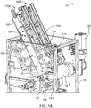
- a molding apparatus 10 for producing fastener products features two molding modules 100a and 100b inside a processing enclosure 16.
- Each molding module includes a base 102, a frame 104, a rotatable roller 106, a resin extrusion head 112, and a linear actuator 108 (e.g., a drive cylinder).
- the molding modules 100a and 100b are positioned to mold resin in collaboration with a pair of spaced-apart, fixed-axis processing rollers 12 and 14.
- the processing rollers 12 and 14 are mounted on chamber 16 and are driven about their respective axes by a motor 28 such as a direct drive motor, a belt drive motor, or a combination of the two. Each roller can be driven by a respective motor.
- the processing rollers form a gap between them, through which gap molding modules 100a and 100b extend.
- structural base 102 is fixed in position with respect to the processing rollers axes, while frame 104 can move along the length of base 102.
- Each base 102 is slidably mounted on a bench 26 that is fixed to chamber 16, allowing its respective molding module to be moved in a lateral direction parallel to the rotation axes of the processing rollers. While only two modules are shown in this example, molding apparatus 10 may include more than two molding modules, such as three, four, or even five or more modules.
- molding apparatus 10 defines a processing direction 25 and performs a continuous extrusion/roll-forming method for forming fastener elements 20 on an integral, resin sheet-form base 19.
- Extrusion head 112 is attached to a bottom end of base 102 and supplies a sheet of molten resin (not shown) to a pressure zone or molding nip 22 defined between rotatable roller 106 and processing roller 12, which functions both as a reaction surface and a drive roll.
- Rotatable roller 106 is attached to a distal end of frame 104, and by operation of the frame the roller 106 is movable toward and away from both rollers 12 and 14.
- Rotatable roller 106 (sometimes referred to herein as mold roll), defines an array of miniature, molding cavities extending inward from its periphery 111 for molding fastener elements 20.
- the pressure in nip 22 forces resin to enter and fill the exposed molding cavities, while excess resin forms base 19 on the peripheral surface of the mold roll and interconnects the filled cavities that form fastener elements 20.
- Mold roll 106 is continuously cooled, e.g., by controlled flow of coolant through its interior, heat is extracted from the product as the product passes through first nip 22 and travels to a second nip 24 between mold roll 106 and processing roller 14, which functions as a counter-rotating drive roll.
- processing rollers 12 and 14, or an external source can provide cooling to the molten resin, as the only cooling source or in collaboration with mold roll 106.
- the heat removal solidifies fastener elements 20 (e.g., hooks), subsequently allowing elements 20 to be peeled from their fixed cavities by drive roll 14, also referred to as a take-off roll. Hooks 20 are then leveled uniformly by a knock-down roller 114 attached to structural base 102.
- mold roll 106 can be configured to form arrays of projections (e.g., straight stems) extending from base 19 that are peeled from the cavities of mold roll 106 and plastically deformed by a knock-down roller to form the fastener elements.
- arrays of projections e.g., straight stems
- each frame 104a and 104b independently moves along its respective base 102a and 102b to position the mold rolls 106a and 106b away from the processing rollers 12 and 14.
- a substrate 18, shown in dashed lines, may be trained about the rollers in order to mold resin on a surface of substrate 18.
- Substrate 18 is preferably a nonwoven fabric.
- frame 104 moves mold roll 106 away from processing rollers 12 and 14, and substrate 18 is then positioned about the processing rollers and mold roll 106, extending in the processing direction 25.
- the apparatus is configured to mold fastener elements while laminating resin base 19 to the surface of substrate 18.
- Substrate 18 is laminated to the resin in pressure nip 22 and is carried about mold roll 106 with the solidifying resin.
- Substrate 18 is then stripped from mold roll 106 at nip 24 with the solidified resin, and exits molding apparatus 10 as the fastener product shown in FIG 1C .
- Mold roll 106 is a passive roller, only rotating by movement of pressure roll 12 and drive roll 14.
- Drive roll 14 engages outer surface 111 of mold roll 106 through resin base 19 on outer surface 111, and pressure roll 12 engages mold roll 106 through the resin dropped into nip 22.
- the rollers When molding on a substrate, the rollers also engage through the thickness of the substrate in the nips.
- FIG. 2 when the frame is extended, the mold roll is spaced from the processing rollers and readily accessible to be changed or serviced. This position also allows other components of apparatus 10 such as the processing rollers 12 and 14 or the frames to be serviced or removed for maintenance, or for a substrate to be threaded between the rolls during setup.
- pressure roll 12 and drive roll 14 have generally the same length, both rollers being longer than mold roll 106 and knock-down roll 114.
- Each molding module 100a and 100b is relatively narrow, and, each can be moved independently in a lateral direction parallel to its mold roll axis. This movement is preferably done with the mold roll retracted, but can also be done during molding. This flexibility allows each mold roll 106a and 106b to be placed in different locations along the length of pressure roll 12, so that each module can apply resin at any selected position across the width of one or more substrate sheets.
- molding module 100 has a structural base 102 with a U-shaped channel with two opposite walls 101a and 101b, a bottom plate 115 connecting both sides at a distal, bottom end, and a pair of linear bearings 117 attached to the back of the U-shaped channel.
- Each wall 101a and 101b defines an open slot 107 in the middle, and a corner piece 129 attached at a distal, upper end.
- each wall 101a and 101b forms an L-shaped structure 118 connected to a linking arm 116 that carries the knock-down roll 114.
- Base 102 has a rail connection (not shown) between both walls 101a and 101b that receives frame 104.
- Linear bearings 117 are configured to be slidably retained within rails of bench 26 (as in FIG. 1A ), and together form a linear bearing guide that allows the molding module 100 to move laterally.
- Knock-down roll 114 is mounted on linking arm 116 that is connected to base 102.
- Linking arm 116 biases knock-down roll 114 downward against the take-off roll by virtue of a spring loaded shaft connection 154 with internal torsion springs and/or linear springs, with a positive stop that can be adjusted to set a desired gap.
- the pressure applied by knock-down roll 114 to the drive roll pushes down against the fastener elements to level them, making the fastener product more uniform.
- Knock-down roll 114 need only be of sufficient width to engage the fastener elements molded by mold roll 106.
- Corner piece 129 is made of a rigid material such as carbon steel and features two exposed surfaces: a side surface 126 and back surface 128, defining between them a corner 130.
- Side surface 126 and back surface 128 are both straight, with back surface 128 being generally perpendicular to side surface 126.
- back surface 128 can be curved or otherwise profiled, and/or extend in a different direction, such as forming an obtuse or an acute angle with side surface 126.
- Corner piece 129 is permanently secured to the rest of base 102.
- Frame 104 has three parts: an internal rail 103 and two external mounting arms 105.
- Internal rail 103 is a long plate that has a top end with a pin block 138 extending beyond the edges of mounting arms 105 when assembled.
- internal rail 103 defines linear bearing rail connections (not shown) to slidably connect to base 102.
- a wider part of internal rail 103 extends beyond slots 107 when assembled.
- Each mounting arm 105 of the frame has recesses 105a for receiving screws to connect to internal rail 103.
- One mounting arm 105 connects to each side of internal rail 103 such that internal rail 103 is disposed inside base 102 and mounting arms 105 are disposed outside the base. This connection constrains frame 104 against relative motion other than in a direction parallel to side surface 126 of base 102, along the length of the slot.
- molding module 100 includes a lever arm 110 that has a first pivot hole 136 for connecting to pin block 138 and a second pivot hole 134 for connecting to drive cylinder 108.
- Lever arm 110 also has one end connected to a pair of cam roller bearings 132, such as needle bearings. Roller bearings 132 are coaxially connected to lever arm 110, with one roller bearing 132 on each side of lever arm 110.
- Pivot hole 136 is located between second pivot hole 134 and roller bearings 132 along the length of the lever arm.
- the shape of lever arm 110 can be altered to adapt for different connections with the drive cylinder, rail connection block and/or roller bearings 132.
- lever arm 110 can include cam rollers or a different object with a bearing surface, including a fixed bearing (cam) surface.
- Lever arm 110 also includes an additional roller bearing 148 coupled to the second pivot 134, to contact a lever support 146 of base 102.
- molding module 100 features drive cylinder 108 that is pivotally coupled to base 102.
- Drive cylinder 108 has a cylinder rod 142 and a cylinder barrel 122.
- Barrel 122 is pivotally connected to base 102 at a pivot coupling between L-shaped structures 118, and rod 142 is pinned to lever arm 110 at second pivot hole 134.
- drive cylinder 108 can be mounted in the opposite direction, with rod 142 connected to the base and barrel 122 connected to lever arm 110, disposed above the lever arm, on an opposite side of the lever arm as the mold roll.
- Drive cylinder 108 may be any type of controllable linear actuator, such as a pneumatic or hydraulic cylinder actuated under fluid pressure, a ball screw actuator, or a linear motor.
- lever arm 110 To move frame 104 along base 102, drive cylinder 108 is actuated to move lever arm 110, which travels along corner piece 129. Starting when drive cylinder is in a retracted position, lever arm 110 is positioned longitudinally parallel to side surface 126. When drive cylinder 108 extends cylinder rod 142, roller bearings 132 roll along corner piece 129, moving from side surface 126, around the corner 130, to back surface 128 of corner piece 129. During this motion, lever arm 110 moves frame 104 with respect to base 102 over a linear stroke of drive cylinder 108 that moves second pivot 134 along a continuous motion path. More specifically, as lever arm 110 moves over the linear stroke of cylinder 108, frame moves mold roll 106 toward pressure roll 12 and drive roll 14 (FIG.
- nip pressure can be controlled by cylinder motion, increasing nip pressure by extending cylinder rod 142 and decreasing nip pressure by retracting cylinder rod 142. Further details of the cylinder operation and related linkage can be found in U.S. Application Number 15/797,164 , entitled “Linear Actuator Leverage” and filed on the same day herewith.
- Lever support 146 helps lever arm 110 move along a continuous motion path, as lever arm 110 moves from the first path segment to the second path segment by allowing cam roller 148 of lever arm 110 to bear against support 146 when roller bearings 132 move along corner 130.
- Support 146 is fixed at a distance from side surface 126, 'pushing' lever arm 110 toward back surface 128 when lever arm 110 is pivoting to move past corner 130 to the second path segment.
- extrusion head 112 is connected to a bottom end of base 102, between mounting arms 105 of frame 104.
- Extrusion head 112 includes a nozzle 112a for introducing molten resin to molding nip 22.
- the position of head 112 is adjustable such as to position nozzle 112a directly above nip 22, such that the extruded molten resin falls vertically into nip 22 under the force of gravity.
- head 112 can be positioned to drop the molten resin onto a surface of pressure roll 12 or the surface of mold roll 106, to be carried into nip 22 by rotation of the rollers.
- Head 112 can be configured to introduce molten resin continuously or, when using a substrate, in a series of discrete amounts, to form islands spaced apart longitudinally over the substrate to form an interrupted strip of fastener elements.
- mold roll 106 includes fixed molding cavities 111a for molding resin, and its periphery is made out of rings, as shown in FIG. 7 .
- Fixed molding cavities 111a extend inward from periphery 111 of mold roll 106.
- Cavities 111a have a shape specifically designed to facilitate both complete filling of the cavities as well as relatively easy removal of the solidified fastener elements 20.
- Cavities 111a are configured so that removing or peeling away fastener elements 20 can be done without opening cavities 111a.
- Each cavity 111a includes a throat 111b having an inwardly tapered configuration, which opens toward periphery 111, such as to allow the removal of fastener element 20 from cavities 111a without breaking or substantially deforming fastener elements 20.
- mold roll 106 includes concentric etched or engraved rings 170, and substantially flat spacer rings 172, which together define molding cavities 111a within which fastener elements are formed.
- each of rings 170 and 172 is provided with an outside diameter of about 250 mm, and a thickness of about 0.15 to 1.0 mm.
- the cavities may only partially extend through a given ring, or may extend fully through a ring and bounded by adjacent surfaces of spacer rings.
- FIG. 5 shows mold roll 106 in position to mold fastener elements, cooperatively engaged with the surfaces of both pressure roll 12 and drive roll 14.
- Mold roll 106 and pressure roll 12 each have a respective rotation axis, with both axes being parallel and lying in a common horizontal plane 'g', such that nip 22 is symmetric about a vertical plane for receiving molten resin dropped from the extrusion nozzle.
- plane g can be tilted to suit a different configuration of apparatus 10.
- Each of rolls 12 and 14 has a diameter of, for example, 250 mm, with a distance 'f' between the rotation axes of pressure roll 12 and drive roll 14 of, for example, 438 mm.
- Wrap angle ⁇ is defined from the centers of nips 22 and 24 (where lines connecting the roll centers cross the nips) and represents the included angle of the portion of the mold roll surface over which the resin is cooled and solidified.
- the resin is sufficiently cooled from molding nip 22 to second nip 24 to be stripped out from cavities 111a by drive roll 14.
- Angle ⁇ is preferably between 190° and 300°, such as 240°. As the mold roll is urged toward the pressure and drive rolls during molding, the minimum gap between the pressure and drive rolls will be necessarily less than the diameter of the drive roll, and angle ⁇ will be always greater than 180°.
- wrap angle ⁇ having a value of 240°, for example, and mold roll 106 having a radius of 250 mm, for example, circumferential cooling distance e is 531 mm.
- This implementation allows the product on mold roll 106 to be carried for a longer time, in comparison to an aligned roll stack where angle ⁇ is 180°. The greater angle ⁇ , the more heat may be removed from the product, enabling higher run speeds.
- a deflector shoe 180 has a circular plate 184 with a cylindrical opened ring 182 coupled to the periphery of plate 184.
- Ring 182 has an uniformly continuous outer surface with a thickness 't' of approximately 25 to 75 millimeters (optimally, sized to fill most of the spacing between adjacent mold rolls) and a diameter similar to the diameter of mold roll 106, and extends about 3 ⁇ 4 of the way around the shoe. In some cases, the shoe diameter can be smaller than the diameter of mold roll 106.
- cylindrical opened ring 182 is configured to receive an end of mounting arm 105, allowing plate 184 to couple to frame 104 adjacent mold roll 106.
- Shoe 180 forms a narrow gap 196 with mold roll 106.
- circular plate 184 has some slots that receive fasteners for connecting to frame 104, and other slots arranged to permit access to a side of mold roll 106 when shoe 180 is mounted on frame 104.
- an open square slot 190 and an L-shaped slot 192 allow access to a side of mold roll 106 for maintenance, disassembly, or feeding mold roll 106 with a cooling fluid.
- Small L-shaped slots 188 and holes 194 receive fasteners for connecting shoe 180 to frame 104, as shown in FIG. 9 .
- fasteners 199 are conventional screws and fasteners 198 are spring loaded fasteners that, when connected, allow shoe 180 to be temporarily separated from the frame after conventional screws 199 have been taken out or loosen. This is useful when spring fasteners 198 are not readily accessible, allowing the assembly to be disconnected and/or easily accessed for maintenance. Details of spring fasteners 198 can be found in U.S. Application Number 15/728,630 , entitled “Threaded Fastening" and filed on October 10, 2017.
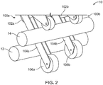
- three molding modules 100a, 100b, and 100c with shoes 180 are spaced apart laterally and aligned along a direction perpendicular to the processing direction for molding resin onto a substrate.
- a substrate feeder 204 such as a roll of substrate, feeds a flexible substrate 200 into the pressure zones 22, for lamination of molten resin 202 onto substrate 200. The lamination takes place in the pressure zones 22 during molding of resin 202 in the arrays of mold cavities.
- Each molding module molds a strip of resin 202, molding together three strips of resin onto substrate 200.
- the removable deflector shoes 180 are secured to respective frames 104a, 104b, and 104c, and are placed on each side of mold rolls 106a, 106b, and 106c. Shoes 180 are arranged to limit separation of substrate 200 from pressure roll 12 as the substrate passes through the nips, keeping substrate 200 from creasing between the mold rolls.
- the adjacent shoes 180 that are attached to separate molding modules are separated by a module separation gap 'c' of between 1.0 and 5.0 mm, with the spacing 'a' and 'b' between longitudinal centers of adjacent mold rolls, for example, 160 mm respectively. Distances 'a' and 'b' can be the same, or the width of each module and/or the separation gaps can be varied to position the mold rolls as desired for different applications.
- shoes 180 can be selectively removed, such as to allow creasing or puckering of substrate 200 in selected areas between pressure zones.
- a corresponding single module can be provided with a roll of multiple cavity regions, with a die that provides corresponding, spaced streams of resin to the cavity regions.
Landscapes
- Engineering & Computer Science (AREA)
- Mechanical Engineering (AREA)
- Manufacturing & Machinery (AREA)
- Moulds For Moulding Plastics Or The Like (AREA)
- Casting Or Compression Moulding Of Plastics Or The Like (AREA)
Claims (17)
- Formvorrichtung (10), die eine Verarbeitungsrichtung (25) definiert und umfasst:eine Reaktionsoberfläche (12); undeine Mehrzahl von Formmodulen (100, 100a, 100b, 100c), die in einer lateralen Richtung senkrecht zur Verarbeitungsrichtung (25) beabstandet sind, zum gleichzeitigen Formen in jeweiligen mit den Modulen (100, 100a, 100b, 100c) assoziierten Bereichen, wobei jedes Formmodul (100, 100a, 100b, 100c) umfasst:einen Rahmen (104, 104a, 104b, 104c); undeine drehbare Walze (106, 106a, 106b, 106c), die mit dem Rahmen (104, 104a, 104b, 104c) gekoppelt ist, wobei die drehbare Walze (106, 106a, 106b, 106c) unter Zusammenwirken mit der Reaktionsoberfläche (12) eine jeweilige Druckzone (22) definiert, wobei mindestens eine der Reaktionsoberfläche (12) und der drehbaren Walze (106, 106a, 106b, 106c) eine Anordnung von Formhohlräumen (111a) definiert;wobei die drehbare Walze (106, 106a, 106b, 106c) jedes Formmoduls (100, 100a, 100b, 100c) in Bezug auf eine Nähe zur Reaktionsoberfläche (12) durch eine gesteuerte Betätigung des Rahmens (104, 104a, 104b, 104c) des Formmoduls unabhängig bewegbar ist.
- Formvorrichtung (10) nach Anspruch 1, ferner umfassend mindestens eine Harzquelle (112), die ausgelegt ist, geschmolzenes Harz in die Druckzone (22) einzubringen, um in die Formhohlräume (111a) durch Druck in der Druckzone (22) gedrückt zu werden, insbesondere wobei jedes Formmodul (100, 100a, 100b, 100c) eine jeweilige Harzquelle (112) umfasst.
- Formvorrichtung (10) nach Anspruch 2, wobei die Harzquelle (112) ausgelegt ist, einen kontinuierlichen Strom von Harz zur Druckzone (22) zum Ausbilden einer kontinuierlichen Schicht (19) von Harz zuzuführen, und/oder
- Formvorrichtung (10) nach Anspruch 2, wobei die Harzquelle (112) ausgelegt ist, geschmolzenes Harz in diskontinuierlichen Mengen zum Ausbilden einer unterbrochenen Schicht von Harz zuzuführen.
- Formvorrichtung (10) nach einem der obigen Ansprüche, wobei die Formmodule (100, 100a, 100b, 100c) angeordnet sind, Harz an unterschiedlichen Abschnitten eines oder mehrerer Substrate (18, 200) zu formen, die sich zwischen der Walze (106, 106a, 106b, 106c) und der Reaktionsoberfläche (12) bewegen.
- Formvorrichtung (10) nach einem der obigen Ansprüche, wobei die Formmodule (100, 100a, 100b, 100c) angeordnet sind, Harz an einer gemeinsamen Oberfläche eines Substrats (18, 200) zu formen, das sich zwischen den Walzen (106, 106a, 106b, 106c) und der Reaktionsoberfläche (12) bewegt, insbesondere wobei jedes Formmodul (100, 100a, 100b, 100c) ausgelegt ist, Druck auf einen ersten Bereich des Substrats (18, 200) in der Druckzone (22) aufzubringen, während ein zweiter Bereich des Substrats (18, 200) zwischen zwei Druckzonen (22) angeordnet ist.
- Formvorrichtung (10) nach einem der obigen Ansprüche, wobei die Formhohlräume (111a) so geformt sind, dass sie diskrete Stiele bilden, die sich von einer Schicht (19) von Harz erstrecken, die zwischen der Reaktionsoberfläche (12) und der drehbaren Walze (106, 106a, 106b, 106c) ausgebildet ist, insbesondere wobei die Formhohlräume (111a) so geformt sind, dass sie Klettverschlusselemente (20) mit Köpfen ausbilden, die über die Schicht (19) von Harz überhängen, insbesondere wobei die Formvorrichtung (10) mindestens eine Niederdrückwalze (114) umfasst, die angeordnet ist, die Verschlusselemente (20) einheitlich in Bezug auf die Schicht (19) von Harz zu ebnen, insbesondere wobei die Formvorrichtung (10) mehrere Niederdrückwalzen (114) umfasst, wobei jede Niederdrückwalze (114) mit einem entsprechenden Formmodul (100, 100a, 100b, 100c) assoziiert ist.
- Formvorrichtung (10) nach einem der obigen Ansprüche, wobei die Reaktionsoberfläche (12) eine Oberfläche einer drehbaren Druckwalze (12) umfasst.
- Formvorrichtung (10) nach Anspruch 8, wobei die Druckzone (22) zwischen der drehbaren Walze (106, 106a, 106b, 106c) und der Druckwalze (12) einen Walzenspalt (22) umfasst, in den Harz unter Scherkraft gezogen wird, die durch eine Drehung der Druckwalze (12) entsteht, und/oder
wobei die drehbare Walze (106, 106a, 106b, 106c) eine passive Walze ist, die ausgelegt ist, zumindest teilweise durch eine Bewegung der Druckwalze (12) angetrieben zu werden, insbesondere ferner umfassend eine Antriebswalze (14), die von der Druckwalze (12) beabstandet ist und eine Außenfläche (111) der drehbaren Walze (106, 106a, 106b, 106c) über an der Außenfläche angeordnetes Harz in Eingriff bringt. - Formvorrichtung (10) nach einem der Ansprüche 2 bis 9, ferner umfassend einen Substratvorschub (204), der angeordnet ist, ein flexibles Substrat (18, 200) in die Druckzonen (22) zwischen den drehbaren Walzen (106, 106a, 106b, 106c) und der Reaktionsoberfläche (12) zur Laminierung des geschmolzenen Harzes auf das flexible Substrat (18, 200) in mindestens einer der Druckzonen (22) während eines Formens von Harz in den Anordnungen von Hohlräumen (111a) vorzuschieben, insbesondere ferner umfassend mindestens einen Ablenkschuh (180), der zwischen drehbaren Walzen (106, 106a, 106b, 106c) angeordnet ist und eine Beabstandung des Substrats (18, 200) von der Reaktionsoberfläche (12) begrenzt, insbesondere wobei die Formvorrichtung (10) mehrere Ablenkschuhe (180) umfasst, wobei jeder Schuh an dem Rahmen (104, 104a, 104b, 104c) eines jeweiligen Formmoduls (100, 100a, 100b, 100c) gesichert ist.
- Formvorrichtung (10) nach einem der obigen Ansprüche, wobei jede drehbare Walze (106, 106a, 106b, 106c) auch unabhängig in Bezug auf die Reaktionsoberfläche (12) in einer lateralen Richtung parallel zu einer Drehachse der Walze bewegbar ist, insbesondere wobei jede drehbare Walze (106, 106a, 106b, 106c) durch laterales Bewegen ihres Formmoduls (100, 100a, 100b, 100c) lateral bewegbar ist.
- Formvorrichtung (10) nach einem der obigen Ansprüche, wobei die drehbare Walze (106, 106a, 106b, 106c) die Anordnung von Formhohlräumen (111a) in einer Umfangsfläche (111) der drehbaren Walze (106, 106a, 106b, 106c) definiert, und/oder ferner umfassend, für jedes Formmodul, einen linearen Aktuator (108), der betätigbar ist, um die drehbare Walze (106, 106a, 106b, 106c) in Bezug auf die Reaktionsoberfläche (12) zu bewegen.
- Verfahren zum Formen eines Verschlussprodukts entlang einer Verarbeitungsrichtung (25), wobei das Verfahren umfasst:Positionieren mehrerer Formmodule (100, 100a, 100b, 100c) in Bezug auf eine gemeinsame Reaktionsoberfläche (12), wobei jedes Modul eine jeweilige Formwalze (106, 106a, 106b, 106c) aufweist, die eine jeweilige Druckzone (22) unter Zusammenwirken mit der Reaktionsoberfläche (12) ausbildet, wobei die Druckzonen (22) entlang der gemeinsamen Reaktionsoberfläche (12) gemäß dem Positionieren der Module (100, 100a, 100b, 100c) beabstandet sind, wobei die Formwalzen (106, 106a, 106b, 106c) jeweils eine Umfangsfläche (111) aufweisen und eine Anordnung von Hohlräumen (111a) definieren, die sich in die Formwalze von der Umfangsfläche (111) erstrecken;Einbringen von geschmolzenem Harz separat in jede Druckzone (22) derart, dass während einer Drehung der Formwalzen (106, 106a, 106b, 106c) in Bezug auf die Reaktionsoberfläche (12) das eingebrachte Harz in die Hohlräume (111a) in den Druckzonen (22) gedrückt wird, um Anordnungen von Vorsprüngen (20) auszubilden, die sich von Basisschichten (19) von Harz erstrecken, die an den Umfangsflächen (111) der Formwalzen ausgebildet sind; und dannHerausziehen der Vorsprünge aus den Hohlräumen (lila), während die Basisschichten (19) von den Umfangsflächen (111) abgezogen werden.
- Verfahren nach Anspruch 13, wobei die Vorsprünge (20) geformte Verschlusselemente (20) umfassen, und/oder ferner umfassend, nach dem Herausziehen der Vorsprünge (20), plastisches Verformen der Vorsprünge, um Verschlusselemente (20) auszubilden.
- Verfahren nach Anspruch 13 oder Anspruch 14, wobei das Positionieren jedes Formmoduls (100, 100a, 100b, 100c) Bewegen des Moduls in eine Richtung senkrecht zur Verarbeitungsrichtung (25) umfasst, insbesondere wobei das Positionieren jedes Formmoduls (100, 100a, 100b, 100c) ferner, nach Bewegen des Moduls in der Richtung senkrecht zur Verarbeitungsrichtung (25), Bewegen der Formwalze (106, 106a, 106b, 106c) des Moduls hin zur Reaktionsoberfläche (12) umfasst, und/oder wobei Bewegen der Formwalze (106, 106a, 106b, 106c) hin zur Reaktionsoberfläche (12) zuerst Bewegen der Formwalze (106, 106a, 106b, 106c) bei einer relativ schnellen Geschwindigkeit und dann Bewegen der Formwalze (106, 106a, 106b, 106c) bei einer langsameren Geschwindigkeit umfasst.
- Verfahren nach einem der Ansprüche 13 bis 15, ferner umfassend Positionieren eines Substrats (18, 200) zwischen den Formmodulen (100, 100a, 100b, 100c) und der gemeinsamen Reaktionsoberfläche (12) derart, dass, während das Harz in die Hohlräume (111a) in den Druckzonen (22) gedrückt wird, das Harz auf das Substrat (18, 200) laminiert wird, um die Basisschichten (19) als Schichten auszubilden, die durch freigelegte Bereiche des Substrats (18, 200) beabstandet sind, insbesondere ferner umfassend Umpositionieren der Formmodule (100, 100a, 100b, 100c) während einer Unterbrechung bei der Einbringung von geschmolzenem Harz, um einen Abstand der Basisschichten (19) auf dem Substrat (18, 200) zu verändern, und/oder ferner umfassend Begrenzen einer Beabstandung des Substrats (18, 200) von der Reaktionsoberfläche (12) durch Verwenden mindestens eines mit den Formmodulen (100, 100a, 100b, 100c) gekoppelten Ablenkschuhs (180).
- Verfahren nach einem der Ansprüche 13 bis 16, wobei die Reaktionsoberfläche (12) eine angetriebene Druckwalze (12) umfasst, und wobei, während einer Einbringung des geschmolzenen Harzes, eine angetriebene Drehung der Druckwalze (12) eine Drehung der Formwalze (106, 106a, 106b, 106c) bewirkt, insbesondere ferner umfassend eine Antriebswalze (14), die von der Druckwalze (12) beabstandet ist, und wobei, während einer Einbringung des geschmolzenen Harzes, eine angetriebene Drehung der Antriebswalze (14) eine Drehung der Formwalze (106, 106a, 106b, 106c) unter Zusammenwirken mit der Druckwalze (12) bewirkt.
Applications Claiming Priority (2)
| Application Number | Priority Date | Filing Date | Title |
|---|---|---|---|
| US15/797,198 US10556369B2 (en) | 2017-10-30 | 2017-10-30 | Modular molding assembly |
| PCT/EP2018/078156 WO2019086239A1 (en) | 2017-10-30 | 2018-10-16 | Modular molding assembly |
Publications (2)
| Publication Number | Publication Date |
|---|---|
| EP3703927A1 EP3703927A1 (de) | 2020-09-09 |
| EP3703927B1 true EP3703927B1 (de) | 2021-12-08 |
Family
ID=64023998
Family Applications (1)
| Application Number | Title | Priority Date | Filing Date |
|---|---|---|---|
| EP18793601.8A Active EP3703927B1 (de) | 2017-10-30 | 2018-10-16 | Modulare formanordnung |
Country Status (3)
| Country | Link |
|---|---|
| US (2) | US10556369B2 (de) |
| EP (1) | EP3703927B1 (de) |
| WO (1) | WO2019086239A1 (de) |
Families Citing this family (3)
| Publication number | Priority date | Publication date | Assignee | Title |
|---|---|---|---|---|
| US11110632B2 (en) | 2017-10-30 | 2021-09-07 | Velcro Ip Holdings Llc | Roll-molding |
| US10556369B2 (en) | 2017-10-30 | 2020-02-11 | Velcro BVBA | Modular molding assembly |
| US11000978B2 (en) * | 2018-06-26 | 2021-05-11 | The Boeing Company | Gap filler roller assembly |
Family Cites Families (63)
| Publication number | Priority date | Publication date | Assignee | Title |
|---|---|---|---|---|
| FR1117251A (fr) | 1954-12-21 | 1956-05-22 | Galon en matière plastique | |
| US3230134A (en) | 1958-11-19 | 1966-01-18 | Us Rubber Co | Plastic carpet and method of making same |
| US3267191A (en) | 1961-07-07 | 1966-08-16 | Us Rubber Co | Method of forming a rubber sheet having stubs extending from one surface |
| US3312583A (en) | 1963-10-02 | 1967-04-04 | James J Rochlis | Apertured and staggered molded pile product |
| US3266113A (en) | 1963-10-07 | 1966-08-16 | Minnesota Mining & Mfg | Interreacting articles |
| US3462332A (en) | 1965-03-05 | 1969-08-19 | High Polymer Chem Ind Ltd | Method of continuously providing a fastener on a thermoplastic film |
| US3445915A (en) | 1966-10-21 | 1969-05-27 | Scovill Manufacturing Co | Method of producing folded thermoplastic strips for sliding clasp fasteners |
| BR6801575D0 (pt) | 1968-08-01 | 1973-01-23 | H Alberts | Um fecho de correr |
| US3557413A (en) | 1968-09-23 | 1971-01-26 | William H Engle | Nonmechanical closure |
| US3616020A (en) | 1969-01-15 | 1971-10-26 | Standard Oil Co | Extrusion coating of a heat fusible foam sheet |
| US3594865A (en) | 1969-07-10 | 1971-07-27 | American Velcro Inc | Apparatus for molding plastic shapes in molding recesses formed in moving endless wire dies |
| US3608035A (en) | 1969-08-01 | 1971-09-21 | Opti Holding Ag | Method of making slide fasteners |
| FR2082591A5 (en) | 1970-03-20 | 1971-12-10 | Velcro France | Separable plastic fixing bands - prepd by continuous extrusion and subvision |
| US3726752A (en) | 1970-09-14 | 1973-04-10 | American Velcro Inc | Adhesive polyamide laminate with a coating comprising resorcinol,phenol and triisocyanate |
| AT333222B (de) | 1971-03-26 | 1976-11-10 | Repla Int | Verfahren und einrichtung zur herstellung eines klettenverschlusses |
| US3758657A (en) | 1971-12-01 | 1973-09-11 | American Velcro Inc | Production of a continuous molded plastic strip |
| US4001366A (en) | 1972-01-03 | 1977-01-04 | Ingrip Fasteners Inc. | Method for making self-gripping devices having integral trains of gripping elements |
| US3843760A (en) | 1972-04-04 | 1974-10-22 | Riegel Textile Corp | Channel cloth extrusion apparatus and process |
| US3956056A (en) | 1972-11-20 | 1976-05-11 | Uniroyal Inc. | Fabric coating by extrusion die-calendering apparatus and method |
| GB1472405A (en) | 1973-09-27 | 1977-05-04 | Ici Ltd | Production of pile surfaced materials |
| JPS5218228A (en) | 1975-08-01 | 1977-02-10 | Hitachi Ltd | Butterfly valve |
| US4097634A (en) | 1976-04-19 | 1978-06-27 | Minnesota Mining And Manufacturing Company | Thermoplastic resin molding of complex decorative relief |
| FR2364004A1 (fr) | 1976-09-08 | 1978-04-07 | Louison Et Cie V | Ruban d'attache auto-fixable |
| ES453167A1 (es) | 1976-11-10 | 1977-11-16 | Velero Espanola S A | Mejoras en los procedimientos de fabricacion continua de e- lementos monobloques autofijables. |
| NZ187101A (en) | 1977-05-04 | 1981-05-01 | Scovill Australia Pty Ltd | Continuous casting of slide fastener interlocking elements onto tape using pair of casting rollers |
| JPS54109939A (en) | 1978-02-15 | 1979-08-29 | Mitsui Petrochem Ind Ltd | Oxidation reactor for preparing aromatic carboxylic acid |
| US4329196A (en) | 1979-08-16 | 1982-05-11 | Monsanto Company | Method of making a three-dimensional laminate |
| US4794028A (en) | 1984-04-16 | 1988-12-27 | Velcro Industries B.V. | Method for continuously producing a multi-hook fastner member and product of the method |
| US4872243A (en) | 1984-04-16 | 1989-10-10 | Velcro Industries B.V. | Multi-hook fastener member |
| US4775310A (en) | 1984-04-16 | 1988-10-04 | Velcro Industries B.V. | Apparatus for making a separable fastener |
| US4615084A (en) | 1984-08-21 | 1986-10-07 | Erblok Associates | Multiple hook fastener media and method and system for making |
| CA1285122C (en) | 1985-07-17 | 1991-06-25 | Richard N. Hatch | Separable fasteners for attachment to other objects |
| US4933224A (en) | 1985-07-17 | 1990-06-12 | Velcro Industries, B.V. | Method for adapting separable fasteners for attachment to other objects |
| US4784890A (en) | 1986-06-20 | 1988-11-15 | Minnesota Mining And Manufacturing Company | Fastener assembly with peripheral temporary attachment layer |
| KR940006314B1 (ko) | 1987-12-15 | 1994-07-16 | 가부시끼가이샤 구라레 | 죔쇠 부재 |
| US4894060A (en) | 1988-01-11 | 1990-01-16 | Minnesota Mining And Manufacturing Company | Disposable diaper with improved hook fastener portion |
| US4999067A (en) | 1989-02-13 | 1991-03-12 | Erblok Associates | Method for making a hermaphrodite hook and loop fasteners |
| US5260015A (en) | 1991-08-16 | 1993-11-09 | Velcro Industries, B.V. | Method for making a laminated hook fastener |
| JP2756211B2 (ja) | 1992-06-17 | 1998-05-25 | ワイケイケイ株式会社 | 両面に係合片を有する一体成形面ファスナーの製造方法及びその装置 |
| JP2744384B2 (ja) | 1992-07-22 | 1998-04-28 | ワイケイケイ株式会社 | 裏面に裏部材を有する係合部材の製造方法及びその装置 |
| JPH08299032A (ja) * | 1995-05-09 | 1996-11-19 | Ykk Kk | 成形面ファスナー |
| JP3705635B2 (ja) | 1995-12-07 | 2005-10-12 | 新日本石油化学株式会社 | プラスチックフィルムの圧延装置 |
| US5945131A (en) | 1997-04-16 | 1999-08-31 | Velcro Industries B.V. | Continuous molding of fastener products and the like and products produced thereby |
| US6099289A (en) | 1997-08-25 | 2000-08-08 | Velcro Industries B.V. | Forming mold cavities |
| US6066281A (en) | 1998-06-16 | 2000-05-23 | Velcro Industries B.V. | Fastener products and their production |
| US6991843B2 (en) * | 1999-01-15 | 2006-01-31 | Velcro Industries B.V. | Fasteners engageable with loops of nonwoven fabrics and with other open structures, and methods and machines for making fasteners |
| ES2299479T3 (es) | 2000-03-14 | 2008-06-01 | Velcro Industries B.V. | Cierre de gancho y presilla. |
| DE60134841D1 (de) | 2000-03-14 | 2008-08-28 | Velcro Ind | Verfahren zur herstellung eines dehnfähigen verschlusses |
| US6656563B1 (en) * | 2000-05-23 | 2003-12-02 | Velcro Industries B.V. | Segmented separable fastener |
| ES2292589T3 (es) | 2000-05-26 | 2008-03-16 | Velcro Industries B.V. | Material de bucles para una sujeccion por ganchos y bucles. |
| TWI227196B (en) * | 2002-02-22 | 2005-02-01 | Clopay Plastic Prod Co | Film, laminated sheet and methods of making same |
| US7108814B2 (en) * | 2004-11-24 | 2006-09-19 | Velcro Industries B.V. | Molded touch fasteners and methods of manufacture |
| JP4698334B2 (ja) | 2005-05-23 | 2011-06-08 | 東芝機械株式会社 | シート成形装置およびシート成形装置のロール間隙制御方法 |
| US8240180B2 (en) | 2009-06-01 | 2012-08-14 | Processing Technologies, Llc | Height positioning mechanism for roll stand assembly on an apparatus for continuously forming an extruded sheet product |
| US9399333B2 (en) | 2012-04-18 | 2016-07-26 | Velcro BVBA | Forming laminated touch fasteners |
| WO2015045077A1 (ja) | 2013-09-26 | 2015-04-02 | Ykk株式会社 | 面ファスナー成形装置及びその動作方法、並びに面ファスナーの製造方法 |
| US9649792B2 (en) * | 2013-10-15 | 2017-05-16 | Velcro BVBA | Forming longitudinally pleated products |
| DE102014004020A1 (de) | 2014-03-20 | 2015-09-24 | Brückner Maschinenbau GmbH & Co. KG | Winkelverstellbare Anpress- oder Nipwalze |
| EP3015243A1 (de) | 2014-11-03 | 2016-05-04 | Starlinger & Co. Gesellschaft m.b.H. | Vorrichtung zur Herstellung und Glättung von Kunststofffolien bzw. Kunststoffplatten |
| US10436236B2 (en) | 2017-10-10 | 2019-10-08 | Velcro BVBA | Threaded fastening |
| US10894345B2 (en) | 2017-10-30 | 2021-01-19 | Velcro BVBA | Linear actuator leverage |
| US11110632B2 (en) | 2017-10-30 | 2021-09-07 | Velcro Ip Holdings Llc | Roll-molding |
| US10556369B2 (en) | 2017-10-30 | 2020-02-11 | Velcro BVBA | Modular molding assembly |
-
2017
- 2017-10-30 US US15/797,198 patent/US10556369B2/en active Active
-
2018
- 2018-10-16 EP EP18793601.8A patent/EP3703927B1/de active Active
- 2018-10-16 WO PCT/EP2018/078156 patent/WO2019086239A1/en not_active Ceased
-
2019
- 2019-12-10 US US16/708,502 patent/US10906214B2/en active Active
Also Published As
| Publication number | Publication date |
|---|---|
| US10906214B2 (en) | 2021-02-02 |
| US20190126520A1 (en) | 2019-05-02 |
| EP3703927A1 (de) | 2020-09-09 |
| US10556369B2 (en) | 2020-02-11 |
| US20200108530A1 (en) | 2020-04-09 |
| WO2019086239A1 (en) | 2019-05-09 |
Similar Documents
| Publication | Publication Date | Title |
|---|---|---|
| EP3703924B1 (de) | Walzformung | |
| US10906214B2 (en) | Modular molding assembly | |
| EP1009606B1 (de) | Kontinuierliches formen von befestigungsprodukten und dergleichen sowie auf diese weise hergestellte produkte | |
| CN102785319B (zh) | 成形设备的改进或者涉及成形设备的改进 | |
| EP2346661B1 (de) | Formungsverfahren | |
| EP3703925B1 (de) | Hebelwirkung eines linearaktuators | |
| US12202177B2 (en) | Molding resin to form continuous structures | |
| KR102033709B1 (ko) | 벨트프레스식 플라스틱시트 제조장치 | |
| CA2455085A1 (en) | Food product marking systems and methods | |
| JP3336246B2 (ja) | 射出成形同時絵付装置及び方法 | |
| DE69903712T2 (de) | Warmformverfahren und vorrichtung | |
| CN217892000U (zh) | 一种粉末成型机用防粘连机构 | |
| CN216397743U (zh) | 一种多料带冲压铆合成型五金模具 | |
| CN116749563B (zh) | 一种发热包包装材料制造工艺及冷却设备 | |
| CN120055104A (zh) | 一种罐盖生产用冲压装置 | |
| JPH0790285B2 (ja) | 金属板成型装置 | |
| CN118181622A (zh) | 一种可调挤压辊组件及共挤地板生产线 | |
| KR20030095773A (ko) | 금속판의 절곡 가공 방법 및 장치 | |
| AU2013219175A1 (en) | Forming methods | |
| JP2004017328A (ja) | 成形同時転写品の製造装置 |
Legal Events
| Date | Code | Title | Description |
|---|---|---|---|
| STAA | Information on the status of an ep patent application or granted ep patent |
Free format text: STATUS: UNKNOWN |
|
| STAA | Information on the status of an ep patent application or granted ep patent |
Free format text: STATUS: THE INTERNATIONAL PUBLICATION HAS BEEN MADE |
|
| PUAI | Public reference made under article 153(3) epc to a published international application that has entered the european phase |
Free format text: ORIGINAL CODE: 0009012 |
|
| STAA | Information on the status of an ep patent application or granted ep patent |
Free format text: STATUS: REQUEST FOR EXAMINATION WAS MADE |
|
| 17P | Request for examination filed |
Effective date: 20200406 |
|
| AK | Designated contracting states |
Kind code of ref document: A1 Designated state(s): AL AT BE BG CH CY CZ DE DK EE ES FI FR GB GR HR HU IE IS IT LI LT LU LV MC MK MT NL NO PL PT RO RS SE SI SK SM TR |
|
| AX | Request for extension of the european patent |
Extension state: BA ME |
|
| DAV | Request for validation of the european patent (deleted) | ||
| DAX | Request for extension of the european patent (deleted) | ||
| RAP1 | Party data changed (applicant data changed or rights of an application transferred) |
Owner name: VELCRO IP HOLDINGS LLC |
|
| REG | Reference to a national code |
Ref country code: DE Ref legal event code: R079 Ref document number: 602018027948 Country of ref document: DE Free format text: PREVIOUS MAIN CLASS: B29C0043460000 Ipc: B29C0043280000 |
|
| GRAP | Despatch of communication of intention to grant a patent |
Free format text: ORIGINAL CODE: EPIDOSNIGR1 |
|
| STAA | Information on the status of an ep patent application or granted ep patent |
Free format text: STATUS: GRANT OF PATENT IS INTENDED |
|
| RIC1 | Information provided on ipc code assigned before grant |
Ipc: B29C 43/28 20060101AFI20210707BHEP Ipc: B29C 43/46 20060101ALI20210707BHEP Ipc: B29C 43/24 20060101ALI20210707BHEP Ipc: B29C 48/00 20190101ALI20210707BHEP Ipc: B29C 48/35 20190101ALI20210707BHEP Ipc: A44B 18/00 20060101ALI20210707BHEP Ipc: B29L 31/00 20060101ALN20210707BHEP |
|
| RIC1 | Information provided on ipc code assigned before grant |
Ipc: B29C 43/28 20060101AFI20210713BHEP Ipc: B29C 43/46 20060101ALI20210713BHEP Ipc: B29C 43/24 20060101ALI20210713BHEP Ipc: B29C 48/00 20190101ALI20210713BHEP Ipc: B29C 48/35 20190101ALI20210713BHEP Ipc: A44B 18/00 20060101ALI20210713BHEP Ipc: B29L 31/00 20060101ALN20210713BHEP |
|
| INTG | Intention to grant announced |
Effective date: 20210802 |
|
| GRAS | Grant fee paid |
Free format text: ORIGINAL CODE: EPIDOSNIGR3 |
|
| GRAA | (expected) grant |
Free format text: ORIGINAL CODE: 0009210 |
|
| STAA | Information on the status of an ep patent application or granted ep patent |
Free format text: STATUS: THE PATENT HAS BEEN GRANTED |
|
| AK | Designated contracting states |
Kind code of ref document: B1 Designated state(s): AL AT BE BG CH CY CZ DE DK EE ES FI FR GB GR HR HU IE IS IT LI LT LU LV MC MK MT NL NO PL PT RO RS SE SI SK SM TR |
|
| REG | Reference to a national code |
Ref country code: GB Ref legal event code: FG4D |
|
| REG | Reference to a national code |
Ref country code: AT Ref legal event code: REF Ref document number: 1453421 Country of ref document: AT Kind code of ref document: T Effective date: 20211215 Ref country code: CH Ref legal event code: EP |
|
| REG | Reference to a national code |
Ref country code: DE Ref legal event code: R096 Ref document number: 602018027948 Country of ref document: DE |
|
| REG | Reference to a national code |
Ref country code: IE Ref legal event code: FG4D |
|
| REG | Reference to a national code |
Ref country code: LT Ref legal event code: MG9D |
|
| REG | Reference to a national code |
Ref country code: NL Ref legal event code: MP Effective date: 20211208 |
|
| PG25 | Lapsed in a contracting state [announced via postgrant information from national office to epo] |
Ref country code: RS Free format text: LAPSE BECAUSE OF FAILURE TO SUBMIT A TRANSLATION OF THE DESCRIPTION OR TO PAY THE FEE WITHIN THE PRESCRIBED TIME-LIMIT Effective date: 20211208 Ref country code: LT Free format text: LAPSE BECAUSE OF FAILURE TO SUBMIT A TRANSLATION OF THE DESCRIPTION OR TO PAY THE FEE WITHIN THE PRESCRIBED TIME-LIMIT Effective date: 20211208 Ref country code: FI Free format text: LAPSE BECAUSE OF FAILURE TO SUBMIT A TRANSLATION OF THE DESCRIPTION OR TO PAY THE FEE WITHIN THE PRESCRIBED TIME-LIMIT Effective date: 20211208 Ref country code: BG Free format text: LAPSE BECAUSE OF FAILURE TO SUBMIT A TRANSLATION OF THE DESCRIPTION OR TO PAY THE FEE WITHIN THE PRESCRIBED TIME-LIMIT Effective date: 20220308 |
|
| REG | Reference to a national code |
Ref country code: AT Ref legal event code: MK05 Ref document number: 1453421 Country of ref document: AT Kind code of ref document: T Effective date: 20211208 |
|
| PG25 | Lapsed in a contracting state [announced via postgrant information from national office to epo] |
Ref country code: SE Free format text: LAPSE BECAUSE OF FAILURE TO SUBMIT A TRANSLATION OF THE DESCRIPTION OR TO PAY THE FEE WITHIN THE PRESCRIBED TIME-LIMIT Effective date: 20211208 Ref country code: NO Free format text: LAPSE BECAUSE OF FAILURE TO SUBMIT A TRANSLATION OF THE DESCRIPTION OR TO PAY THE FEE WITHIN THE PRESCRIBED TIME-LIMIT Effective date: 20220308 Ref country code: LV Free format text: LAPSE BECAUSE OF FAILURE TO SUBMIT A TRANSLATION OF THE DESCRIPTION OR TO PAY THE FEE WITHIN THE PRESCRIBED TIME-LIMIT Effective date: 20211208 Ref country code: HR Free format text: LAPSE BECAUSE OF FAILURE TO SUBMIT A TRANSLATION OF THE DESCRIPTION OR TO PAY THE FEE WITHIN THE PRESCRIBED TIME-LIMIT Effective date: 20211208 Ref country code: GR Free format text: LAPSE BECAUSE OF FAILURE TO SUBMIT A TRANSLATION OF THE DESCRIPTION OR TO PAY THE FEE WITHIN THE PRESCRIBED TIME-LIMIT Effective date: 20220309 |
|
| PG25 | Lapsed in a contracting state [announced via postgrant information from national office to epo] |
Ref country code: NL Free format text: LAPSE BECAUSE OF FAILURE TO SUBMIT A TRANSLATION OF THE DESCRIPTION OR TO PAY THE FEE WITHIN THE PRESCRIBED TIME-LIMIT Effective date: 20211208 |
|
| PG25 | Lapsed in a contracting state [announced via postgrant information from national office to epo] |
Ref country code: SM Free format text: LAPSE BECAUSE OF FAILURE TO SUBMIT A TRANSLATION OF THE DESCRIPTION OR TO PAY THE FEE WITHIN THE PRESCRIBED TIME-LIMIT Effective date: 20211208 Ref country code: SK Free format text: LAPSE BECAUSE OF FAILURE TO SUBMIT A TRANSLATION OF THE DESCRIPTION OR TO PAY THE FEE WITHIN THE PRESCRIBED TIME-LIMIT Effective date: 20211208 Ref country code: RO Free format text: LAPSE BECAUSE OF FAILURE TO SUBMIT A TRANSLATION OF THE DESCRIPTION OR TO PAY THE FEE WITHIN THE PRESCRIBED TIME-LIMIT Effective date: 20211208 Ref country code: PT Free format text: LAPSE BECAUSE OF FAILURE TO SUBMIT A TRANSLATION OF THE DESCRIPTION OR TO PAY THE FEE WITHIN THE PRESCRIBED TIME-LIMIT Effective date: 20220408 Ref country code: ES Free format text: LAPSE BECAUSE OF FAILURE TO SUBMIT A TRANSLATION OF THE DESCRIPTION OR TO PAY THE FEE WITHIN THE PRESCRIBED TIME-LIMIT Effective date: 20211208 Ref country code: EE Free format text: LAPSE BECAUSE OF FAILURE TO SUBMIT A TRANSLATION OF THE DESCRIPTION OR TO PAY THE FEE WITHIN THE PRESCRIBED TIME-LIMIT Effective date: 20211208 Ref country code: CZ Free format text: LAPSE BECAUSE OF FAILURE TO SUBMIT A TRANSLATION OF THE DESCRIPTION OR TO PAY THE FEE WITHIN THE PRESCRIBED TIME-LIMIT Effective date: 20211208 |
|
| PG25 | Lapsed in a contracting state [announced via postgrant information from national office to epo] |
Ref country code: PL Free format text: LAPSE BECAUSE OF FAILURE TO SUBMIT A TRANSLATION OF THE DESCRIPTION OR TO PAY THE FEE WITHIN THE PRESCRIBED TIME-LIMIT Effective date: 20211208 Ref country code: AT Free format text: LAPSE BECAUSE OF FAILURE TO SUBMIT A TRANSLATION OF THE DESCRIPTION OR TO PAY THE FEE WITHIN THE PRESCRIBED TIME-LIMIT Effective date: 20211208 |
|
| REG | Reference to a national code |
Ref country code: DE Ref legal event code: R097 Ref document number: 602018027948 Country of ref document: DE |
|
| PG25 | Lapsed in a contracting state [announced via postgrant information from national office to epo] |
Ref country code: IS Free format text: LAPSE BECAUSE OF FAILURE TO SUBMIT A TRANSLATION OF THE DESCRIPTION OR TO PAY THE FEE WITHIN THE PRESCRIBED TIME-LIMIT Effective date: 20220408 |
|
| PLBE | No opposition filed within time limit |
Free format text: ORIGINAL CODE: 0009261 |
|
| STAA | Information on the status of an ep patent application or granted ep patent |
Free format text: STATUS: NO OPPOSITION FILED WITHIN TIME LIMIT |
|
| PG25 | Lapsed in a contracting state [announced via postgrant information from national office to epo] |
Ref country code: DK Free format text: LAPSE BECAUSE OF FAILURE TO SUBMIT A TRANSLATION OF THE DESCRIPTION OR TO PAY THE FEE WITHIN THE PRESCRIBED TIME-LIMIT Effective date: 20211208 Ref country code: AL Free format text: LAPSE BECAUSE OF FAILURE TO SUBMIT A TRANSLATION OF THE DESCRIPTION OR TO PAY THE FEE WITHIN THE PRESCRIBED TIME-LIMIT Effective date: 20211208 |
|
| 26N | No opposition filed |
Effective date: 20220909 |
|
| PG25 | Lapsed in a contracting state [announced via postgrant information from national office to epo] |
Ref country code: SI Free format text: LAPSE BECAUSE OF FAILURE TO SUBMIT A TRANSLATION OF THE DESCRIPTION OR TO PAY THE FEE WITHIN THE PRESCRIBED TIME-LIMIT Effective date: 20211208 |
|
| PG25 | Lapsed in a contracting state [announced via postgrant information from national office to epo] |
Ref country code: MC Free format text: LAPSE BECAUSE OF FAILURE TO SUBMIT A TRANSLATION OF THE DESCRIPTION OR TO PAY THE FEE WITHIN THE PRESCRIBED TIME-LIMIT Effective date: 20211208 Ref country code: IT Free format text: LAPSE BECAUSE OF FAILURE TO SUBMIT A TRANSLATION OF THE DESCRIPTION OR TO PAY THE FEE WITHIN THE PRESCRIBED TIME-LIMIT Effective date: 20211208 |
|
| REG | Reference to a national code |
Ref country code: CH Ref legal event code: PL |
|
| P01 | Opt-out of the competence of the unified patent court (upc) registered |
Effective date: 20230424 |
|
| REG | Reference to a national code |
Ref country code: BE Ref legal event code: MM Effective date: 20221031 |
|
| GBPC | Gb: european patent ceased through non-payment of renewal fee |
Effective date: 20221016 |
|
| PG25 | Lapsed in a contracting state [announced via postgrant information from national office to epo] |
Ref country code: LU Free format text: LAPSE BECAUSE OF NON-PAYMENT OF DUE FEES Effective date: 20221016 |
|
| PG25 | Lapsed in a contracting state [announced via postgrant information from national office to epo] |
Ref country code: LI Free format text: LAPSE BECAUSE OF NON-PAYMENT OF DUE FEES Effective date: 20221031 Ref country code: FR Free format text: LAPSE BECAUSE OF NON-PAYMENT OF DUE FEES Effective date: 20221031 Ref country code: CH Free format text: LAPSE BECAUSE OF NON-PAYMENT OF DUE FEES Effective date: 20221031 |
|
| PG25 | Lapsed in a contracting state [announced via postgrant information from national office to epo] |
Ref country code: BE Free format text: LAPSE BECAUSE OF NON-PAYMENT OF DUE FEES Effective date: 20221031 |
|
| PG25 | Lapsed in a contracting state [announced via postgrant information from national office to epo] |
Ref country code: IE Free format text: LAPSE BECAUSE OF NON-PAYMENT OF DUE FEES Effective date: 20221016 Ref country code: GB Free format text: LAPSE BECAUSE OF NON-PAYMENT OF DUE FEES Effective date: 20221016 |
|
| PG25 | Lapsed in a contracting state [announced via postgrant information from national office to epo] |
Ref country code: CY Free format text: LAPSE BECAUSE OF FAILURE TO SUBMIT A TRANSLATION OF THE DESCRIPTION OR TO PAY THE FEE WITHIN THE PRESCRIBED TIME-LIMIT Effective date: 20211208 |
|
| PG25 | Lapsed in a contracting state [announced via postgrant information from national office to epo] |
Ref country code: MK Free format text: LAPSE BECAUSE OF FAILURE TO SUBMIT A TRANSLATION OF THE DESCRIPTION OR TO PAY THE FEE WITHIN THE PRESCRIBED TIME-LIMIT Effective date: 20211208 Ref country code: HU Free format text: LAPSE BECAUSE OF FAILURE TO SUBMIT A TRANSLATION OF THE DESCRIPTION OR TO PAY THE FEE WITHIN THE PRESCRIBED TIME-LIMIT; INVALID AB INITIO Effective date: 20181016 |
|
| PG25 | Lapsed in a contracting state [announced via postgrant information from national office to epo] |
Ref country code: MT Free format text: LAPSE BECAUSE OF FAILURE TO SUBMIT A TRANSLATION OF THE DESCRIPTION OR TO PAY THE FEE WITHIN THE PRESCRIBED TIME-LIMIT Effective date: 20211208 |
|
| PG25 | Lapsed in a contracting state [announced via postgrant information from national office to epo] |
Ref country code: TR Free format text: LAPSE BECAUSE OF FAILURE TO SUBMIT A TRANSLATION OF THE DESCRIPTION OR TO PAY THE FEE WITHIN THE PRESCRIBED TIME-LIMIT Effective date: 20211208 |
|
| PGFP | Annual fee paid to national office [announced via postgrant information from national office to epo] |
Ref country code: DE Payment date: 20250923 Year of fee payment: 8 |