EP1535682A1 - Suppression des vibrations - Google Patents
Suppression des vibrations Download PDFInfo
- Publication number
- EP1535682A1 EP1535682A1 EP20040253226 EP04253226A EP1535682A1 EP 1535682 A1 EP1535682 A1 EP 1535682A1 EP 20040253226 EP20040253226 EP 20040253226 EP 04253226 A EP04253226 A EP 04253226A EP 1535682 A1 EP1535682 A1 EP 1535682A1
- Authority
- EP
- European Patent Office
- Prior art keywords
- shank
- weight
- vibration
- holder
- Prior art date
- Legal status (The legal status is an assumption and is not a legal conclusion. Google has not performed a legal analysis and makes no representation as to the accuracy of the status listed.)
- Withdrawn
Links
Images

Classifications
-
- B—PERFORMING OPERATIONS; TRANSPORTING
- B23—MACHINE TOOLS; METAL-WORKING NOT OTHERWISE PROVIDED FOR
- B23B—TURNING; BORING
- B23B29/00—Holders for non-rotary cutting tools; Boring bars or boring heads; Accessories for tool holders
-
- B—PERFORMING OPERATIONS; TRANSPORTING
- B23—MACHINE TOOLS; METAL-WORKING NOT OTHERWISE PROVIDED FOR
- B23B—TURNING; BORING
- B23B29/00—Holders for non-rotary cutting tools; Boring bars or boring heads; Accessories for tool holders
- B23B29/02—Boring bars
- B23B29/022—Boring bars with vibration reducing means
-
- B—PERFORMING OPERATIONS; TRANSPORTING
- B23—MACHINE TOOLS; METAL-WORKING NOT OTHERWISE PROVIDED FOR
- B23B—TURNING; BORING
- B23B27/00—Tools for turning or boring machines; Tools of a similar kind in general; Accessories therefor
- B23B27/002—Tools for turning or boring machines; Tools of a similar kind in general; Accessories therefor with vibration damping means
-
- B—PERFORMING OPERATIONS; TRANSPORTING
- B23—MACHINE TOOLS; METAL-WORKING NOT OTHERWISE PROVIDED FOR
- B23B—TURNING; BORING
- B23B29/00—Holders for non-rotary cutting tools; Boring bars or boring heads; Accessories for tool holders
- B23B29/02—Boring bars
-
- B—PERFORMING OPERATIONS; TRANSPORTING
- B23—MACHINE TOOLS; METAL-WORKING NOT OTHERWISE PROVIDED FOR
- B23B—TURNING; BORING
- B23B29/00—Holders for non-rotary cutting tools; Boring bars or boring heads; Accessories for tool holders
- B23B29/03—Boring heads
-
- B—PERFORMING OPERATIONS; TRANSPORTING
- B23—MACHINE TOOLS; METAL-WORKING NOT OTHERWISE PROVIDED FOR
- B23B—TURNING; BORING
- B23B29/00—Holders for non-rotary cutting tools; Boring bars or boring heads; Accessories for tool holders
- B23B29/04—Tool holders for a single cutting tool
-
- Y—GENERAL TAGGING OF NEW TECHNOLOGICAL DEVELOPMENTS; GENERAL TAGGING OF CROSS-SECTIONAL TECHNOLOGIES SPANNING OVER SEVERAL SECTIONS OF THE IPC; TECHNICAL SUBJECTS COVERED BY FORMER USPC CROSS-REFERENCE ART COLLECTIONS [XRACs] AND DIGESTS
- Y10—TECHNICAL SUBJECTS COVERED BY FORMER USPC
- Y10T—TECHNICAL SUBJECTS COVERED BY FORMER US CLASSIFICATION
- Y10T82/00—Turning
- Y10T82/25—Lathe
- Y10T82/2585—Tool rest
-
- Y—GENERAL TAGGING OF NEW TECHNOLOGICAL DEVELOPMENTS; GENERAL TAGGING OF CROSS-SECTIONAL TECHNOLOGIES SPANNING OVER SEVERAL SECTIONS OF THE IPC; TECHNICAL SUBJECTS COVERED BY FORMER USPC CROSS-REFERENCE ART COLLECTIONS [XRACs] AND DIGESTS
- Y10—TECHNICAL SUBJECTS COVERED BY FORMER USPC
- Y10T—TECHNICAL SUBJECTS COVERED BY FORMER US CLASSIFICATION
- Y10T83/00—Cutting
- Y10T83/929—Tool or tool with support
- Y10T83/9319—Toothed blade or tooth therefor
Definitions
- the present invention relates to a low-cost vibration-suppressing cutting tool that can significantly reduce chatter vibrations mainly in cutting operations in which chatter vibrations cause problems.
- chatter vibrations can be suppressed by a method that uses inertia by incorporating a damper or similar member into a holder.
- the size of the holder is limited by the hole diameter of a workpiece. Consequently, the amount of overhang must be increased by using a slender shank. This structure tends to generate chatter vibrations.
- the prior art on the vibration-suppressing cutting tool mainly relates to a boring bar. Therefore, the following explanation is made by mainly referring to the boring bar as an example.
- a hole 21 is drilled from the rear end of a shank portion 2 of the holder.
- a damper 22 is inserted into the hole 21 to place it at the tip portion of the holder near the cutting corner.
- a bar-shaped core 23 made of cemented carbide is inserted into the remaining portion of the hole 21.
- Another published Japanese patent application, Tokukaihei 6-31507 has disclosed a vibration-suppressing cutting tool in which a deep hole is formed at the center portion of the holder to house a weight.
- an example of the conventional vibration-suppressing cutting tool has a deep hole drilled in a long holder to insert a damper so that it can be placed at the deepest portion of the hole.
- This structure increases the machining cost for producing an inside diameter-cutting holder, in particular, which has a long, small-diameter shank, because the hole must be drilled by using a gun drill or the like.
- Another example of the conventional vibration-suppressing cutting tool has a large hollow portion for inserting the weight of the damper. This structure decreases the stiffness of the holder. In addition, the complicated structure poses a problem of increasing the cost.
- An object of the present invention is to offer a vibration-suppressing cutting tool that can solve the above-described problems posed by conventional vibration-suppressing cutting tools and that is provided with a holder which is low-cost, which has an extremely high effect in suppressing chatter vibrations, which has a simple structure, and which is capable of adapting to a wide range of cutting diameter and cutting condition.
- the present invention achieves the foregoing object by offering the following vibration-suppressing cutting tool.
- the tool comprises a holder comprising a shank portion provided with a pocket having the shape of a nearly rectangular solid.
- the pocket In the cross section of the shank, the pocket has a width of 50% to 100% of the shank diameter or the shank width and a height of 20% to 50% of the shank height.
- a weight is inserted into the pocket such that the weight is movable but unable to rush out.
- the weight has the shape of a nearly rectangular solid and is made of a material having a specific gravity comparable to or greater than that of the material of the shank portion.
- the pocket may be formed such that:
- the pocket may also be formed such that:
- the pocket may also be formed such that:
- the vibration-suppressing cutting tool may have the following structure:
- the present invention offers the following vibration-suppressing cutting tool.
- the tool comprises a holder comprising a shank portion provided with a plurality of holes that extend along the width of the shank, that are placed along the longitudinal axis of the shank, and that are placed at a position relatively close to the tip of the shank portion.
- a weight having the shape of a bar is inserted into each of the holes such that the weight is movable but unable to rush out.
- the weight is made of a material having a specific gravity comparable to or greater than that of the material of the shank portion.
- a holder 1 has a shank portion 2 provided with a pocket 4 having the shape of a nearly rectangular solid.
- the pocket 4 has a width b of 50% to 100% of the shank diameter d or the shank width wand a height h of 20% to 50% of the shank height H.
- a weight 5 is inserted into the pocket 4 such that the weight is movable but unable to rush out.
- the weight 5 has the shape of a nearly rectangular solid and is made of a material having a specific gravity comparable to or greater than that of the material of the shank portion 2.
- the weight 5 be made of a material having a specific gravity of at least 7.8, such as cemented carbide or heavy metal.
- the above-described vibration-suppressing cutting tool may have a structure shown in one of the following figures:
- the present invention also offers another vibration-suppressing cutting tool having the following structure.
- a holder has a shank portion provided with a plurality of holes that extend along the width of the shank and that are placed along the longitudinal axis of the shank. The holes function as the above-described pocket.
- a weight having the shape of a bar is inserted into each of the holes such that the weight is movable but unable to rush out.
- the weight is made of a material having a specific gravity comparable to or greater than that of the material of the shank portion. It is desirable that in this tool also, the holes for housing the weights be placed at a position relatively close to the tip of the holder.
- the present invention places the nearly-rectangular-solid weight in a direction more effective against the vibration by considering the direction of the vibration.
- the more effective direction is a direction at which the area of the weight making contact with the inside wall of the pocket is secured more widely. This arrangement enables the application of the load by the weight to the inside wall of the pocket with a wide distribution. This distributed application of the load is effective, so that the chatter vibration can be significantly reduced.
- the structure of the present invention allows the machining of the pocket from the side of the holder. This machining method renders the production easier, reducing the production cost substantially. As a result, a vibration-suppressing cutting tool can be offered at a lower price.
- a structure is described above in which the shank and head portions of the holder are separately formed to allow the weight to be inserted into the pocket, formed in the shank portion, from the tip of the shank portion.
- the weight most effective in suppressing the chatter vibration can be inserted. Consequently, this structure eliminates the need to machine a large damper-inserting portion.
- the structure can be simplified with minimizing the reduction in the stiffness of the shank due to the formation of the pocket.
- the cost of the tool (holder) can be reduced notably.
- vibration-suppressing cutting tool of the present invention is further explained below by referring to various examples.
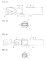
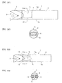
- FIGS. 6A and 6B show an embodiment of the vibration-suppressing cutting tool of the present invention.
- the tool shown is a boring bar having the following structure.
- An indexable insert 7 is clamped to the tip portion of a holder 1 with a clamping means 8 so that it can be easily attached and detached.
- a shank portion 2 of the holder 1 is provided with a hole passing through the shank from one side to the other.
- the hole is machined by a method such as electrical-discharge machining at a position relatively close to the tip of the holder 1.
- the hole acts as a pocket 4.
- a weight 5 made of cemented carbide having a specific gravity of 15.1 is inserted into the pocket 4. Both openings of the pocket 4 are closed with caps 6 so that the weight 5 is unable to rush out to the outside.
- the weight 5 housed in the pocket 4 has a size (height a and width f ) smaller than the size of the pocket by 0.15 mm or so. In other words, the weight 5 is allowed to move within the range of the clearance with the wall of the pocket 4.
- the weight 5 it is absolutely necessary for the weight 5 to move in the pocket 4. If the interference of the wall of the pocket 4 prohibits the movement, the chatter vibration cannot be effectively suppressed. If the weight 5 is excessively small, because of the insufficient weight of the weight 5, sufficient effect in suppressing the chatter vibration cannot be achieved.
- a study by the present inventors has revealed that when the shank portion of the holder has a diameter as relatively small as 20 mm or less, the weight 5 smaller than the pocket 4 by 0.05 to 0.5 mm or so in size can have the effect. In particular, when the weight 5 is smaller than the pocket 4 by 0.1 to 0.3 mm or so, the effect is maximized. When the shank diameter is larger than 20 mm, even a larger clearance between the weight 5 and the pocket 4 can secure the weight 5 having a sufficient weight. More specifically, the weight 5 smaller than the pocket 4 by 0.5 mm or more can have the effect.
- the weight 5 When the holder 1 is made of steel, which has a specific gravity of 7.8, the weight 5 is required to have a specific gravity of at least 7.8 to achieve a sufficient effect.
- the weight 5 having a higher specific gravity is advantageous because it allows the pocket to have a smaller size to achieve the same effect.
- a suitable material for the weight 5 is cemented carbide having a specific gravity of 14 to 16 or heavy metal having a specific gravity of 18 or so, because they are easily available and facilitate the machining. Of course, when a material having a specific gravity higher than that of these materials is available, it may be used.
- the holder 1 decreases its stiffness, decreasing the machining precision of the tool (machined dimensions and surface roughness) or increasing the tendency of the chatter vibration of the tool, contrary to the object of the intention. If the pocket 4 is excessively small, the weight 5 becomes small accordingly, decreasing the effect of suppressing the chatter vibration. More specifically, if the pocket 4 is excessively small in the height h , the tool, such as an end mill, must have a small diameter to machine the pocket. This makes the machining difficult.
- the pocket 4 have a height h of 20% to 50% of the shank diameter d or the shank height H and a width b of 50% to 100% of the shank diameter d or the shank width w .
- the following result can be derived from the comprehensive judgment by considering the effect of preventing the chatter vibration, the degradation of the machining precision due to the bending of the holder at the time of machining, and the easiness in production.
- the pocket When the shank portion of the holder has a diameter as relatively small as 20 mm or less, it is most desirable that the pocket have a height h of 20% to 40% of the shank diameter d or the shank height H and a width b of 70% to 95% of the shank diameter d or the shank width w .
- the present inventors found that a good result can be achieved when the length c of the pocket 4 is 50% to 250% of the shank diameter d and the distance e from the tip of the tool to the position of the pocket is 100% to 250% of the shank diameter d
- the most effective result was achieved when the length c of the pocket 4 was 100% to 180% or so of the shank diameter d and the distance e was 150% to 220% or so of the shank diameter d .
- the shank diameter is larger than 20 mm, even a small pocket 4 can have a vibration-suppressing effect. More specifically, the effect can be achieved even when the pocket 4 has a width b as small as 50% or so of the shank diameter.
- the positioning angle ⁇ of the pocket 4 shown in Figs. 7A and 7B may be determined in accordance with the direction at which the cutting force is applied.
- the pocket machined horizontally can sufficiently achieve the purpose of suppressing the chatter vibration.
- the effect can be increased when the weight 5 is inserted into a pocket whose side constituting the width is perpendicular to the resultant force of the principal force and the back force of the cutting force.
- the pocket 4 may be machined vertically, as shown in Figs. 8A and 8B.
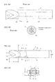
- Figures 9A to 9C show an embodiment that is effective in the case where the machining precision is considered particularly important.
- the tool shown in Figs. 6A and 6B can have a large weight, so that it can easily enhance the effect of suppressing the chatter vibration. However, because it has a pocket 4 passing through the shank portion 2, the stiffness of the holder tends to decrease, decreasing the machining precision.
- the vibration-suppressing cutting tool shown in Figs. 9A to 9C can solve the problem.
- a shank portion 2 is provided with a pocket 4 having the shape of a nearly rectangular solid.
- the pocket 4 is machined with an end mill from a side 1a of a holder 1 opposite to the side at which a cutting corner 7a is placed.
- both ends of the pocket 4 have the shape of an arc.
- the pocket 4 forms a blind hole, which leaves a residual thickness of about 2 mm at a side 1b at which the cutting corner 7a is placed.
- the opening of the pocket 4 at the side 1a is closed with a cap 6 so that the weight 5 is unable to rush out.
- the cap 6 may be made of the same steel as used for the holder 1. Nevertheless, when the cap 6 made of cemented carbide is securely attached to the holder 1, the reduction in the stiffness of the holder due to the formation of the pocket can be decreased.
- the vibration-suppressing cutting tool shown in Figs. 9A to 9C has a pocket 4 with the shape of a blind hole. This is an important point in enhancing the applicability of the tool further.
- the present inventors first produced the tool shown in Figs. 6A and 6B and confirmed that it has a notably high effect in suppressing the chatter vibration. Although the structure shown in Figs. 6A and 6B has a high effect in suppressing the chatter vibration, the reduction in the stiffness of the holder cannot be avoided. Consequently, there was apprehension that the machining precision degrades.
- FIGs. 10A to 10D show a cross-sectional configuration at Section X ⁇ X of the holder shown in Fig. 1A.
- Figs. 10A to 10D in the structure shown in Figs. 6A and 6B (see Fig. 10A), which forms the pocket 4 by a through hole, the amount of deformation due to a load is about 40% larger than that of the inside diameter-cutting tool having an ordinary steel shank without a vibration-suppressing mechanism.
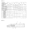
- the weight 5 to be inserted into the pocket may have the shape of a rectangular solid as shown in Fig. 13. Even when the weight has a flat face at its both ends, if the weight can have a sufficient weight, the weight having the shape shown in Fig. 13 is advantageous in that it can eliminate the machining of the arc-shaped face.
- the tool produced for the experiment had a holder having the shape in accordance with the ISO Standard S12M-STUPR1103.
- the tool had the following dimensions (see Figs. 1A and 1B):
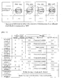
- Invented samples 1 to 6 and Comparative samples 1 to 5 were produced by varying the width of the pocket and the size and material of the weight. Comparative sample 2 was produced with no clearance between the weight and the pocket. Comparative sample 4 was produced by using a holder having an ordinary steel shank. Comparative sample 5 was produced by forming the shank with cemented carbide. Other tools than Comparative sample 5 had a shank made of steel.
- the experiment was conducted by varying the amount of overhang from the tool holding portion of the machine as follows: 48, 60, 72, and 84 mm.
- the result was evaluated on the basis of whether the chatter vibration was generated or not.
- the evaluation results are shown in Fig. 12.
- the sign " ⁇ " shows that no chatter vibration was generated, and the sign " ⁇ " shows that chatter vibrations were generated.
- all Invented samples had a notably high effect in suppressing the chatter vibration.
- Invented samples 1, 3, and 5 showed a chatter vibration-suppressing effect superior to Comparative sample 5, which had a holder formed with cemented carbide.
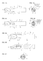
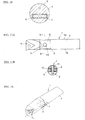
- Figures 14A and 14B show yet another embodiment.
- a shank portion 2 and a head portion 3 of a holder 1 are first separately formed and then combined with each other to form an integrated body.
- the head portion 3 may either be bonded to the shank portion 2 unseparably or be attached to it separably so that the head portion 3 can be replaced when it is broken.
- This structure allows the formation of a pocket 4 having an opening at the tip of the shank portion 2 so that a weight 5 can be inserted into it.
- the head portion 3 acts as a cap, eliminating the need to provide a specific cap.
- FIGS 15A and 15B show yet another embodiment, in which pockets 4 are machined from both sides of a holder 1 so that the central solid portion of the shank can be left intact.
- This structure houses weights 5 smaller than those housed in other structures described above. As a result, the effect of suppressing the chatter vibration decreases slightly. Nevertheless, this structure allows the formation of a longitudinally extending oil hole at the central solid portion between the two pockets. This oil hole can be used to supply a cutting fluid effectively to the cutting corner.
- Figure 16 shows a vibration-suppressing cutting tool in which a pocket 4 is provided off center in a shank portion 2 downwardly ("upwardly” is also possible). This structure also allows the formation of an oil hole 9 in the remaining solid portion above the pocket 4.
- FIGs 17A and 17B show another method for preventing a weight 5 from rushing out from a pocket 4.
- the weight 5 is provided with a hole 10 that passes through the weight 5 from the bottom to the top.
- a holding pin 11 thinner than the diameter of the hole 10 is inserted into it to prevent the weight 5 from rushing out. No cap is required in this structure.
- Figure 18 shows yet another vibration-suppressing cutting tool.
- a plurality of holes 12 extending along the width of the shank portion 2 are placed along the longitudinal axis of the shank (the holes may be either through holes or blind holes).
- the holes 12 are placed at a position relatively close to the tip of the shank.
- a weight 5 is inserted into each of the holes 12 such that the weight is movable but unable to rush out from the hole.
- This structure inevitably uses a small weight. Consequently, the chatter vibration-suppressing effect is lower than that of the above-described structures. However, it can easily suppress the reduction in the stiffness of the holder.
- the holes 12 are round holes and the weights 5 are round bars, this type can further simplify the production of the holder, reducing the production cost.
- an inside diameter-cutting tool which is represented by a boring bar, as an example.
- the present invention can also be applied to a cutting tool for grooving, a cutting tool for threading, and a general cutting tool for outside-diameter turning work, all of which tend to generate chatter vibrations.
- the present invention is not limited to the turning work. It can also be applied to a tool such as a boring quill to be attached to a milling machine, a machining center, and the like. In this case also, an excellent chatter vibration-suppressing effect can be achieved.
Applications Claiming Priority (2)
| Application Number | Priority Date | Filing Date | Title |
|---|---|---|---|
| JP2003395827 | 2003-11-26 | ||
| JP2003395827 | 2003-11-26 |
Publications (1)
| Publication Number | Publication Date |
|---|---|
| EP1535682A1 true EP1535682A1 (fr) | 2005-06-01 |
Family
ID=34463801
Family Applications (1)
| Application Number | Title | Priority Date | Filing Date |
|---|---|---|---|
| EP20040253226 Withdrawn EP1535682A1 (fr) | 2003-11-26 | 2004-05-28 | Suppression des vibrations |
Country Status (5)
| Country | Link |
|---|---|
| US (1) | US7490536B2 (fr) |
| EP (1) | EP1535682A1 (fr) |
| KR (1) | KR20050050578A (fr) |
| CN (1) | CN100503100C (fr) |
| IL (1) | IL162651A (fr) |
Cited By (7)
| Publication number | Priority date | Publication date | Assignee | Title |
|---|---|---|---|---|
| GB2488431A (en) * | 2011-02-24 | 2012-08-29 | Kennametal Inc | Tool holder for a milling machine tool |
| CN103252680A (zh) * | 2013-04-24 | 2013-08-21 | 华中科技大学 | 一种铣削加工颤振主动控制系统及其方法 |
| US8882406B2 (en) | 2011-02-24 | 2014-11-11 | Kennametal Inc. | Milling cutter, especially a round-head milling cutter |
| CN106239246A (zh) * | 2016-08-13 | 2016-12-21 | 哈尔滨理工大学 | 可调阻尼和刚度的电流变减振抑颤刀柄及减振抑颤方法 |
| EP3932596A1 (fr) * | 2020-06-30 | 2022-01-05 | Seco Tools Tooling Systems | Barre d'alésage et outil de forage non rotatif et agencement de forage comprenant une telle barre d'alésage |
| DE102020115678B4 (de) | 2019-07-17 | 2022-03-03 | Kennametal Inc. | Schneidwerkzeugklingenhalter |
| US11491551B2 (en) | 2017-07-19 | 2022-11-08 | Wohlhaupter Gmbh | Damping apparatus and tool-holding apparatus with such a damping apparatus |
Families Citing this family (24)
| Publication number | Priority date | Publication date | Assignee | Title |
|---|---|---|---|---|
| JP4689997B2 (ja) * | 2003-11-26 | 2011-06-01 | 住友電工ハードメタル株式会社 | 防振切削工具 |
| EP1535682A1 (fr) | 2003-11-26 | 2005-06-01 | Sumitomo Electric Hardmetal Corp. | Suppression des vibrations |
| JP4648072B2 (ja) * | 2005-04-28 | 2011-03-09 | 株式会社日立プラントテクノロジー | ダンパーを備えた工具及びそれを用いた流体機械の羽根車もしくは案内羽根の製造方法 |
| US20110017562A1 (en) * | 2009-07-21 | 2011-01-27 | Hapco Aluminum Pole Products | Vibration damping system for utility poles |
| US8734070B2 (en) | 2010-10-20 | 2014-05-27 | Kennametal Inc. | Toolholder with externally-mounted dynamic absorber |
| EP2457678B1 (fr) * | 2010-11-29 | 2016-03-30 | Techspace Aero S.A. | Outil de coupe monobloc bimatériaux |
| KR101201144B1 (ko) * | 2010-12-28 | 2012-11-13 | 한국기초과학지원연구원 | 진동억제 구조를 구비한 장축 바이트 |
| US8784016B2 (en) | 2011-07-01 | 2014-07-22 | Kennametal Inc. | Rotary cutting tool with vibration damping device |
| DE102011052308B4 (de) * | 2011-07-29 | 2015-02-05 | Schenck Rotec Gmbh | Spannvorrichtung für eine Auswuchtmaschine |
| CN102672217A (zh) * | 2012-05-24 | 2012-09-19 | 山东大学 | 涂层阻尼减振刀杆及其减振测试方法 |
| US20150034427A1 (en) * | 2013-08-02 | 2015-02-05 | Specialized Bicycle Components, Inc. | Brake vibration isolator for bicycle frame |
| CN103447621A (zh) * | 2013-09-09 | 2013-12-18 | 昆山奥德鲁自动化技术有限公司 | 一种减震铰刀 |
| DE102015002483A1 (de) * | 2015-02-27 | 2016-09-01 | Rattunde & Co. Gmbh | Verfahren zur Verringerung des regenerativen Ratterns von Zerspanungsmaschinen |
| US10442014B2 (en) * | 2015-05-21 | 2019-10-15 | Kyocera Corporation | Holder, cutting tool, and method of manufacturing machined product using the same |
| US9993879B1 (en) | 2016-12-05 | 2018-06-12 | Kennametal Inc | Eddy current vibration absorber assembly for cutting tool |
| DE102017204858A1 (de) * | 2017-03-22 | 2018-09-27 | Kennametal Inc. | Zerspanungswerkzeug, insbesondere Bohrstange, sowie Verfahren zur Bearbeitung einer Anzahl von Bohrungen |
| DE102017216860B4 (de) | 2017-09-22 | 2020-03-19 | Kennametal Inc. | Zerspanungswerkzeug, Bearbeitungsvorrichtung sowie Verfahren zur Bearbeitung von Werkstücken |
| ES2724799B2 (es) * | 2018-03-09 | 2020-01-29 | Soraluce S Coop | Torno vertical con absorbedor de vibraciones amortiguado |
| US10953471B2 (en) * | 2018-04-16 | 2021-03-23 | Iscar, Ltd. | External turning tool having a cutting portion with a transverse elongated damping mechanism |
| US20220048149A1 (en) * | 2018-12-18 | 2022-02-17 | Kyocera Corporation | Holder, cutting tool, and method for manufacturing machined product |
| CN109865852A (zh) * | 2019-03-14 | 2019-06-11 | 陈壮壮 | 一种硬质合金刀头 |
| CN114096367B (zh) * | 2019-08-09 | 2023-12-12 | 住友电气工业株式会社 | 切削系统、处理方法以及非易失性计算机可读取的记录介质 |
| CN111872425A (zh) * | 2020-06-18 | 2020-11-03 | 东莞市闻誉实业有限公司 | 车刀及加工装置 |
| CN115055987A (zh) * | 2022-07-05 | 2022-09-16 | 深圳市誉和钻石工具有限公司 | 一种自主型减振刀杆 |
Citations (5)
| Publication number | Priority date | Publication date | Assignee | Title |
|---|---|---|---|---|
| US2426359A (en) * | 1944-06-24 | 1947-08-26 | Lankheet Sander | Boring bar |
| JPS59129602A (ja) * | 1983-01-12 | 1984-07-26 | Mitsubishi Heavy Ind Ltd | 切削用工具ホルダ |
| EP0812641A1 (fr) * | 1996-06-10 | 1997-12-17 | Kabushiki Kaisha Kobe Seiko Sho | Barre d'alésage |
| WO2002020202A1 (fr) * | 2000-09-05 | 2002-03-14 | Nt Engineering Kabushiki Kaisha | Structure destinee a eviter le broutage d'une machine-outil |
| US20030147707A1 (en) * | 2002-02-01 | 2003-08-07 | Perkowski Randy M. | Tunable Toolholder |
Family Cites Families (36)
| Publication number | Priority date | Publication date | Assignee | Title |
|---|---|---|---|---|
| US2699696A (en) * | 1948-11-26 | 1955-01-18 | Heald Machine Co | Tool carrier and vibration-damping means therefor |
| US2641940A (en) * | 1949-08-09 | 1953-06-16 | White Dan | Special boring bar |
| US2563559A (en) | 1949-12-22 | 1951-08-07 | Meyers W F Co | Circular saw having vibration damping means |
| US2656742A (en) | 1950-12-19 | 1953-10-27 | Loyd Y Poole | Boring bar |
| US2842014A (en) * | 1954-05-17 | 1958-07-08 | Paul H Miller | Rigid boring bar |
| US2816769A (en) * | 1955-07-22 | 1957-12-17 | Richard M Noble | Drill bit extension |
| US3642378A (en) | 1969-11-03 | 1972-02-15 | Heald Machine Co | Boring bar |
| US3612222A (en) * | 1970-02-18 | 1971-10-12 | Kearney National Inc | Pole damping system |
| NO128725B (fr) | 1972-01-21 | 1974-01-02 | Trondhjems Nagle Spigerfab | |
| US3828637A (en) * | 1972-02-07 | 1974-08-13 | Dyk Res Corp Van | Web cutter |
| US3774730A (en) * | 1972-04-19 | 1973-11-27 | Nl Industries Inc | Tool holder |
| US3841785A (en) * | 1972-06-09 | 1974-10-15 | K Werther | Boring bar |
| GB1578342A (en) * | 1976-02-05 | 1980-11-05 | Nat Res Dev | Boring bars |
| US4553884A (en) * | 1982-05-10 | 1985-11-19 | Kennametal Inc. | Boring tool and method of reducing vibrations therein |
| US4666350A (en) * | 1984-01-24 | 1987-05-19 | Nicholas Leo P | Boring bar |
| US5135533A (en) * | 1989-02-10 | 1992-08-04 | Petersen Thomas D | Coated gall-resistant surgical saw blades |
| JP2979823B2 (ja) | 1992-02-21 | 1999-11-15 | 三菱マテリアル株式会社 | 切削工具 |
| JPH0631507A (ja) | 1992-07-16 | 1994-02-08 | Mitsubishi Materials Corp | 旋削工具 |
| JPH0631505A (ja) | 1992-07-21 | 1994-02-08 | Mitsubishi Materials Corp | ボーリングバー |
| US5518347A (en) | 1995-05-23 | 1996-05-21 | Design And Manufacturing Solutions, Inc. | Tuned damping system for suppressing vibrations during machining |
| SE519487C2 (sv) | 1998-10-22 | 2003-03-04 | Rolf Zimmergren | Metod och anordning för vibrationsstyrning vid borrande svarvning samt verktygshållare för borrande svarvning |
| JP2000176724A (ja) * | 1998-12-09 | 2000-06-27 | Mitsubishi Materials Corp | 嵌合式切削工具 |
| JP2001062612A (ja) | 1999-08-23 | 2001-03-13 | Tasada Kosakusho:Kk | 穴切削工具 |
| JP4313482B2 (ja) | 1999-09-30 | 2009-08-12 | 京セラ株式会社 | 切削工具 |
| US6443673B1 (en) | 2000-01-20 | 2002-09-03 | Kennametal Inc. | Tunable boring bar for suppressing vibrations and method thereof |
| JP2001328022A (ja) | 2000-05-24 | 2001-11-27 | Mitsubishi Materials Corp | 制振工具 |
| SE522081C2 (sv) | 2000-12-06 | 2004-01-13 | Sandvik Ab | Verktyg för bearbetning i metalliska material |
| SE517878C2 (sv) | 2000-12-08 | 2002-07-30 | Sandvik Ab | Förfarande och anordning för vibrationsdämpning av metalliska verktyg för spånavskiljande bearbetning samt verktyg innefattande en dylik anordning |
| KR100440869B1 (ko) * | 2001-02-19 | 2004-07-19 | 이화다이아몬드공업 주식회사 | 절단용 톱판 |
| JP3714267B2 (ja) | 2001-06-13 | 2005-11-09 | 三菱マテリアル株式会社 | 制振工具 |
| JP2003062703A (ja) | 2001-08-21 | 2003-03-05 | Mitsubishi Materials Corp | 制振工具 |
| JP3847139B2 (ja) | 2001-10-30 | 2006-11-15 | 京セラ株式会社 | 切削工具 |
| JP4689997B2 (ja) * | 2003-11-26 | 2011-06-01 | 住友電工ハードメタル株式会社 | 防振切削工具 |
| EP1535682A1 (fr) | 2003-11-26 | 2005-06-01 | Sumitomo Electric Hardmetal Corp. | Suppression des vibrations |
| US7234379B2 (en) | 2005-06-28 | 2007-06-26 | Ingvar Claesson | Device and a method for preventing or reducing vibrations in a cutting tool |
| US7204662B1 (en) * | 2005-11-17 | 2007-04-17 | Kennametal Inc. | Cutting tool with stress splitter |
-
2004
- 2004-05-28 EP EP20040253226 patent/EP1535682A1/fr not_active Withdrawn
- 2004-06-21 IL IL16265104A patent/IL162651A/en active IP Right Grant
- 2004-11-23 US US10/994,332 patent/US7490536B2/en active Active
- 2004-11-25 KR KR1020040097200A patent/KR20050050578A/ko not_active Application Discontinuation
- 2004-11-26 CN CNB2004800348546A patent/CN100503100C/zh active Active
Patent Citations (5)
| Publication number | Priority date | Publication date | Assignee | Title |
|---|---|---|---|---|
| US2426359A (en) * | 1944-06-24 | 1947-08-26 | Lankheet Sander | Boring bar |
| JPS59129602A (ja) * | 1983-01-12 | 1984-07-26 | Mitsubishi Heavy Ind Ltd | 切削用工具ホルダ |
| EP0812641A1 (fr) * | 1996-06-10 | 1997-12-17 | Kabushiki Kaisha Kobe Seiko Sho | Barre d'alésage |
| WO2002020202A1 (fr) * | 2000-09-05 | 2002-03-14 | Nt Engineering Kabushiki Kaisha | Structure destinee a eviter le broutage d'une machine-outil |
| US20030147707A1 (en) * | 2002-02-01 | 2003-08-07 | Perkowski Randy M. | Tunable Toolholder |
Non-Patent Citations (1)
| Title |
|---|
| PATENT ABSTRACTS OF JAPAN vol. 0082, no. 58 (M - 340) 27 November 1984 (1984-11-27) * |
Cited By (9)
| Publication number | Priority date | Publication date | Assignee | Title |
|---|---|---|---|---|
| GB2488431A (en) * | 2011-02-24 | 2012-08-29 | Kennametal Inc | Tool holder for a milling machine tool |
| US8882406B2 (en) | 2011-02-24 | 2014-11-11 | Kennametal Inc. | Milling cutter, especially a round-head milling cutter |
| CN103252680A (zh) * | 2013-04-24 | 2013-08-21 | 华中科技大学 | 一种铣削加工颤振主动控制系统及其方法 |
| CN106239246A (zh) * | 2016-08-13 | 2016-12-21 | 哈尔滨理工大学 | 可调阻尼和刚度的电流变减振抑颤刀柄及减振抑颤方法 |
| US11491551B2 (en) | 2017-07-19 | 2022-11-08 | Wohlhaupter Gmbh | Damping apparatus and tool-holding apparatus with such a damping apparatus |
| DE102020115678B4 (de) | 2019-07-17 | 2022-03-03 | Kennametal Inc. | Schneidwerkzeugklingenhalter |
| US11534834B2 (en) | 2019-07-17 | 2022-12-27 | Kennametal Inc. | Cutting tool holder with improved dampening effect |
| EP3932596A1 (fr) * | 2020-06-30 | 2022-01-05 | Seco Tools Tooling Systems | Barre d'alésage et outil de forage non rotatif et agencement de forage comprenant une telle barre d'alésage |
| WO2022002546A3 (fr) * | 2020-06-30 | 2022-02-10 | Seco Tools Tooling Systems | Tige de forage et outil de forage non rotatif et agencement de forage comprenant une telle tige de forage |
Also Published As
| Publication number | Publication date |
|---|---|
| KR20050050578A (ko) | 2005-05-31 |
| CN1886223A (zh) | 2006-12-27 |
| US7490536B2 (en) | 2009-02-17 |
| IL162651A0 (en) | 2005-11-20 |
| US20050109182A1 (en) | 2005-05-26 |
| CN100503100C (zh) | 2009-06-24 |
| IL162651A (en) | 2010-04-29 |
Similar Documents
| Publication | Publication Date | Title |
|---|---|---|
| US7490536B2 (en) | Vibration-suppressing cutting tool | |
| JP4689997B2 (ja) | 防振切削工具 | |
| JP6240917B2 (ja) | 孔あけ・面取り複合ツール | |
| US6742968B1 (en) | Milling cutter | |
| CN103447591B (zh) | 四角形的可转位的钻头镶片 | |
| US4671710A (en) | Drill bit | |
| US8579556B2 (en) | Insert for drill, drill and method of cutting work material | |
| EP2260960B1 (fr) | Insert de coupe pour foret, foret et procédé de coupe l'utilisant | |
| US5788431A (en) | Drilling tool | |
| AU615117B2 (en) | Cutting insert with chip control | |
| JP7017553B2 (ja) | 切削インサート、切削工具及び切削加工物の製造方法 | |
| WO2021132357A1 (fr) | Support, outil de coupe, et procédé de fabrication de pièce découpée | |
| JP6923855B1 (ja) | 切削インサート | |
| JP4557663B2 (ja) | 防振切削工具 | |
| KR20200090238A (ko) | 공극 부피 대 재료 부피 비가 큰 단면 3-방향 인덱서블 밀링 인서트 및 이를 위한 인서트 밀 | |
| JP7392119B2 (ja) | ホルダ、切削工具及び切削加工物の製造方法 | |
| JPS6312891Y2 (fr) | ||
| JP4565492B2 (ja) | ブッシュレス深穴加工方法 | |
| JP4843317B2 (ja) | ガイド付きロングドリル | |
| WO2021132337A1 (fr) | Dispositif de retenue, outil de coupe et procédé de fabrication de pièce tranchante | |
| JP2004050349A (ja) | 深穴加工用ツイストドリル | |
| JPH03501583A (ja) | 深穴明け用ドリル | |
| JP2007061990A (ja) | スローアウェイ式工具 | |
| KR100601323B1 (ko) | 비대칭형 트위스트 드릴 | |
| KR20240036820A (ko) | 가이드 패드팁의 접합구조를 갖는 버니싱 드릴 |
Legal Events
| Date | Code | Title | Description |
|---|---|---|---|
| PUAI | Public reference made under article 153(3) epc to a published international application that has entered the european phase |
Free format text: ORIGINAL CODE: 0009012 |
|
| AK | Designated contracting states |
Kind code of ref document: A1 Designated state(s): AT BE BG CH CY CZ DE DK EE ES FI FR GB GR HU IE IT LI LU MC NL PL PT RO SE SI SK TR |
|
| AX | Request for extension of the european patent |
Extension state: AL HR LT LV MK |
|
| AKX | Designation fees paid | ||
| REG | Reference to a national code |
Ref country code: DE Ref legal event code: 8566 |
|
| STAA | Information on the status of an ep patent application or granted ep patent |
Free format text: STATUS: THE APPLICATION IS DEEMED TO BE WITHDRAWN |
|
| 18D | Application deemed to be withdrawn |
Effective date: 20051202 |