EP1535670B1 - Vibrationssieb und Verfahren zur Klassifizierung eines partikulären Material - Google Patents
Vibrationssieb und Verfahren zur Klassifizierung eines partikulären Material Download PDFInfo
- Publication number
- EP1535670B1 EP1535670B1 EP04257158A EP04257158A EP1535670B1 EP 1535670 B1 EP1535670 B1 EP 1535670B1 EP 04257158 A EP04257158 A EP 04257158A EP 04257158 A EP04257158 A EP 04257158A EP 1535670 B1 EP1535670 B1 EP 1535670B1
- Authority
- EP
- European Patent Office
- Prior art keywords
- mesh
- carrier
- core material
- particle diameter
- resin
- Prior art date
- Legal status (The legal status is an assumption and is not a legal conclusion. Google has not performed a legal analysis and makes no representation as to the accuracy of the status listed.)
- Expired - Lifetime
Links
- 238000000034 method Methods 0.000 title claims description 51
- 239000011236 particulate material Substances 0.000 title claims description 21
- 239000002245 particle Substances 0.000 claims description 122
- 239000011162 core material Substances 0.000 claims description 87
- 229920005989 resin Polymers 0.000 claims description 73
- 239000011347 resin Substances 0.000 claims description 73
- 238000009826 distribution Methods 0.000 claims description 34
- 239000000463 material Substances 0.000 claims description 24
- 239000004677 Nylon Substances 0.000 claims description 18
- 238000005452 bending Methods 0.000 claims description 18
- 229920001778 nylon Polymers 0.000 claims description 18
- 229920000728 polyester Polymers 0.000 claims description 9
- 239000010419 fine particle Substances 0.000 claims description 5
- 239000011362 coarse particle Substances 0.000 claims description 3
- 238000002360 preparation method Methods 0.000 description 43
- 229920001577 copolymer Polymers 0.000 description 15
- -1 Mn-Znferrite Inorganic materials 0.000 description 11
- 239000000969 carrier Substances 0.000 description 9
- 230000000052 comparative effect Effects 0.000 description 8
- 229920001296 polysiloxane Polymers 0.000 description 8
- 229910000859 α-Fe Inorganic materials 0.000 description 8
- 239000004698 Polyethylene Substances 0.000 description 7
- 238000004140 cleaning Methods 0.000 description 7
- 239000006185 dispersion Substances 0.000 description 7
- 229920000573 polyethylene Polymers 0.000 description 7
- 229910001220 stainless steel Inorganic materials 0.000 description 7
- 239000010935 stainless steel Substances 0.000 description 7
- 108091008695 photoreceptors Proteins 0.000 description 6
- 229920002050 silicone resin Polymers 0.000 description 6
- 229920002302 Nylon 6,6 Polymers 0.000 description 5
- 238000000576 coating method Methods 0.000 description 5
- 238000004519 manufacturing process Methods 0.000 description 5
- 239000000203 mixture Substances 0.000 description 5
- 229920001225 polyester resin Polymers 0.000 description 5
- 239000004645 polyester resin Substances 0.000 description 5
- 229920000642 polymer Polymers 0.000 description 5
- 239000000843 powder Substances 0.000 description 5
- OKTJSMMVPCPJKN-UHFFFAOYSA-N Carbon Chemical compound [C] OKTJSMMVPCPJKN-UHFFFAOYSA-N 0.000 description 4
- XEEYBQQBJWHFJM-UHFFFAOYSA-N Iron Chemical compound [Fe] XEEYBQQBJWHFJM-UHFFFAOYSA-N 0.000 description 4
- VYPSYNLAJGMNEJ-UHFFFAOYSA-N Silicium dioxide Chemical compound O=[Si]=O VYPSYNLAJGMNEJ-UHFFFAOYSA-N 0.000 description 4
- 239000011248 coating agent Substances 0.000 description 3
- 239000007787 solid Substances 0.000 description 3
- 239000004925 Acrylic resin Substances 0.000 description 2
- 229920000178 Acrylic resin Polymers 0.000 description 2
- UQSXHKLRYXJYBZ-UHFFFAOYSA-N Iron oxide Chemical compound [Fe]=O UQSXHKLRYXJYBZ-UHFFFAOYSA-N 0.000 description 2
- PPBRXRYQALVLMV-UHFFFAOYSA-N Styrene Chemical compound C=CC1=CC=CC=C1 PPBRXRYQALVLMV-UHFFFAOYSA-N 0.000 description 2
- 239000006229 carbon black Substances 0.000 description 2
- 235000019241 carbon black Nutrition 0.000 description 2
- 239000003795 chemical substances by application Substances 0.000 description 2
- 230000003247 decreasing effect Effects 0.000 description 2
- 230000006866 deterioration Effects 0.000 description 2
- 230000005684 electric field Effects 0.000 description 2
- 238000011156 evaluation Methods 0.000 description 2
- NBVXSUQYWXRMNV-UHFFFAOYSA-N fluoromethane Chemical compound FC NBVXSUQYWXRMNV-UHFFFAOYSA-N 0.000 description 2
- 229910052742 iron Inorganic materials 0.000 description 2
- SZVJSHCCFOBDDC-UHFFFAOYSA-N iron(II,III) oxide Inorganic materials O=[Fe]O[Fe]O[Fe]=O SZVJSHCCFOBDDC-UHFFFAOYSA-N 0.000 description 2
- 239000002184 metal Substances 0.000 description 2
- 229910052751 metal Inorganic materials 0.000 description 2
- 229910044991 metal oxide Inorganic materials 0.000 description 2
- 150000004706 metal oxides Chemical class 0.000 description 2
- 239000005011 phenolic resin Substances 0.000 description 2
- 239000000377 silicon dioxide Substances 0.000 description 2
- 239000000126 substance Substances 0.000 description 2
- 238000012360 testing method Methods 0.000 description 2
- XOLBLPGZBRYERU-UHFFFAOYSA-N tin dioxide Chemical compound O=[Sn]=O XOLBLPGZBRYERU-UHFFFAOYSA-N 0.000 description 2
- 229910002012 Aerosil® Inorganic materials 0.000 description 1
- QYEXBYZXHDUPRC-UHFFFAOYSA-N B#[Ti]#B Chemical compound B#[Ti]#B QYEXBYZXHDUPRC-UHFFFAOYSA-N 0.000 description 1
- VYZAMTAEIAYCRO-UHFFFAOYSA-N Chromium Chemical compound [Cr] VYZAMTAEIAYCRO-UHFFFAOYSA-N 0.000 description 1
- 229910017518 Cu Zn Inorganic materials 0.000 description 1
- 229910017752 Cu-Zn Inorganic materials 0.000 description 1
- 229910017943 Cu—Zn Inorganic materials 0.000 description 1
- 229920000877 Melamine resin Polymers 0.000 description 1
- 229910015173 MoB2 Inorganic materials 0.000 description 1
- 229910018605 Ni—Zn Inorganic materials 0.000 description 1
- CTQNGGLPUBDAKN-UHFFFAOYSA-N O-Xylene Chemical compound CC1=CC=CC=C1C CTQNGGLPUBDAKN-UHFFFAOYSA-N 0.000 description 1
- 241000282320 Panthera leo Species 0.000 description 1
- 239000004695 Polyether sulfone Substances 0.000 description 1
- 229920000265 Polyparaphenylene Polymers 0.000 description 1
- 239000004743 Polypropylene Substances 0.000 description 1
- 239000004793 Polystyrene Substances 0.000 description 1
- 239000006087 Silane Coupling Agent Substances 0.000 description 1
- 229920007962 Styrene Methyl Methacrylate Polymers 0.000 description 1
- 229910033181 TiB2 Inorganic materials 0.000 description 1
- 239000006230 acetylene black Substances 0.000 description 1
- 239000002390 adhesive tape Substances 0.000 description 1
- XYLMUPLGERFSHI-UHFFFAOYSA-N alpha-Methylstyrene Chemical compound CC(=C)C1=CC=CC=C1 XYLMUPLGERFSHI-UHFFFAOYSA-N 0.000 description 1
- HSFWRNGVRCDJHI-UHFFFAOYSA-N alpha-acetylene Natural products C#C HSFWRNGVRCDJHI-UHFFFAOYSA-N 0.000 description 1
- 239000012298 atmosphere Substances 0.000 description 1
- 239000011324 bead Substances 0.000 description 1
- 239000011230 binding agent Substances 0.000 description 1
- 229910052791 calcium Inorganic materials 0.000 description 1
- 229910052799 carbon Inorganic materials 0.000 description 1
- 235000013869 carnauba wax Nutrition 0.000 description 1
- 239000004203 carnauba wax Substances 0.000 description 1
- 239000006231 channel black Substances 0.000 description 1
- 229910017052 cobalt Inorganic materials 0.000 description 1
- 239000010941 cobalt Substances 0.000 description 1
- GUTLYIVDDKVIGB-UHFFFAOYSA-N cobalt atom Chemical compound [Co] GUTLYIVDDKVIGB-UHFFFAOYSA-N 0.000 description 1
- 229910052681 coesite Inorganic materials 0.000 description 1
- 239000003086 colorant Substances 0.000 description 1
- 150000001875 compounds Chemical class 0.000 description 1
- 239000012050 conventional carrier Substances 0.000 description 1
- 229910052802 copper Inorganic materials 0.000 description 1
- TVZPLCNGKSPOJA-UHFFFAOYSA-N copper zinc Chemical compound [Cu].[Zn] TVZPLCNGKSPOJA-UHFFFAOYSA-N 0.000 description 1
- 229910052906 cristobalite Inorganic materials 0.000 description 1
- 238000005520 cutting process Methods 0.000 description 1
- 230000007423 decrease Effects 0.000 description 1
- 238000011161 development Methods 0.000 description 1
- 238000003618 dip coating Methods 0.000 description 1
- 230000007613 environmental effect Effects 0.000 description 1
- 239000003822 epoxy resin Substances 0.000 description 1
- 238000005530 etching Methods 0.000 description 1
- 229920006244 ethylene-ethyl acrylate Polymers 0.000 description 1
- 239000006232 furnace black Substances 0.000 description 1
- 239000003365 glass fiber Substances 0.000 description 1
- 238000005469 granulation Methods 0.000 description 1
- 230000003179 granulation Effects 0.000 description 1
- 230000005484 gravity Effects 0.000 description 1
- LNEPOXFFQSENCJ-UHFFFAOYSA-N haloperidol Chemical compound C1CC(O)(C=2C=CC(Cl)=CC=2)CCN1CCCC(=O)C1=CC=C(F)C=C1 LNEPOXFFQSENCJ-UHFFFAOYSA-N 0.000 description 1
- 229910052595 hematite Inorganic materials 0.000 description 1
- 230000002209 hydrophobic effect Effects 0.000 description 1
- 229920000554 ionomer Polymers 0.000 description 1
- LIKBJVNGSGBSGK-UHFFFAOYSA-N iron(3+);oxygen(2-) Chemical compound [O-2].[O-2].[O-2].[Fe+3].[Fe+3] LIKBJVNGSGBSGK-UHFFFAOYSA-N 0.000 description 1
- JEIPFZHSYJVQDO-UHFFFAOYSA-N iron(III) oxide Inorganic materials O=[Fe]O[Fe]=O JEIPFZHSYJVQDO-UHFFFAOYSA-N 0.000 description 1
- 239000003273 ketjen black Substances 0.000 description 1
- 150000002576 ketones Chemical class 0.000 description 1
- 239000007788 liquid Substances 0.000 description 1
- 229910052744 lithium Inorganic materials 0.000 description 1
- 229910052749 magnesium Inorganic materials 0.000 description 1
- 239000000696 magnetic material Substances 0.000 description 1
- 239000006249 magnetic particle Substances 0.000 description 1
- 239000006247 magnetic powder Substances 0.000 description 1
- 229910052748 manganese Inorganic materials 0.000 description 1
- 238000005259 measurement Methods 0.000 description 1
- 239000007769 metal material Substances 0.000 description 1
- 125000000956 methoxy group Chemical group [H]C([H])([H])O* 0.000 description 1
- ADFPJHOAARPYLP-UHFFFAOYSA-N methyl 2-methylprop-2-enoate;styrene Chemical compound COC(=O)C(C)=C.C=CC1=CC=CC=C1 ADFPJHOAARPYLP-UHFFFAOYSA-N 0.000 description 1
- 238000012986 modification Methods 0.000 description 1
- 230000004048 modification Effects 0.000 description 1
- 229910052759 nickel Inorganic materials 0.000 description 1
- 229920001197 polyacetylene Polymers 0.000 description 1
- 229920006122 polyamide resin Polymers 0.000 description 1
- 229920005668 polycarbonate resin Polymers 0.000 description 1
- 239000004431 polycarbonate resin Substances 0.000 description 1
- 229920000647 polyepoxide Polymers 0.000 description 1
- 229920006393 polyether sulfone Polymers 0.000 description 1
- 229920013716 polyethylene resin Polymers 0.000 description 1
- 229920000139 polyethylene terephthalate Polymers 0.000 description 1
- 239000005020 polyethylene terephthalate Substances 0.000 description 1
- 229920001155 polypropylene Polymers 0.000 description 1
- 229920000128 polypyrrole Polymers 0.000 description 1
- 229920002223 polystyrene Polymers 0.000 description 1
- 229920005749 polyurethane resin Polymers 0.000 description 1
- 239000000700 radioactive tracer Substances 0.000 description 1
- 238000007873 sieving Methods 0.000 description 1
- FZHAPNGMFPVSLP-UHFFFAOYSA-N silanamine Chemical compound [SiH3]N FZHAPNGMFPVSLP-UHFFFAOYSA-N 0.000 description 1
- 239000002904 solvent Substances 0.000 description 1
- 238000001228 spectrum Methods 0.000 description 1
- 239000007921 spray Substances 0.000 description 1
- 229910052682 stishovite Inorganic materials 0.000 description 1
- 229910052712 strontium Inorganic materials 0.000 description 1
- 229920003048 styrene butadiene rubber Polymers 0.000 description 1
- 229920001169 thermoplastic Polymers 0.000 description 1
- 239000004416 thermosoftening plastic Substances 0.000 description 1
- 229910052905 tridymite Inorganic materials 0.000 description 1
- 238000002604 ultrasonography Methods 0.000 description 1
- 230000000007 visual effect Effects 0.000 description 1
- 238000005406 washing Methods 0.000 description 1
- 239000008096 xylene Substances 0.000 description 1
- 229910052725 zinc Inorganic materials 0.000 description 1
Images

Classifications
-
- B—PERFORMING OPERATIONS; TRANSPORTING
- B07—SEPARATING SOLIDS FROM SOLIDS; SORTING
- B07B—SEPARATING SOLIDS FROM SOLIDS BY SIEVING, SCREENING, SIFTING OR BY USING GAS CURRENTS; SEPARATING BY OTHER DRY METHODS APPLICABLE TO BULK MATERIAL, e.g. LOOSE ARTICLES FIT TO BE HANDLED LIKE BULK MATERIAL
- B07B1/00—Sieving, screening, sifting, or sorting solid materials using networks, gratings, grids, or the like
- B07B1/42—Drive mechanisms, regulating or controlling devices, or balancing devices, specially adapted for screens
-
- G—PHYSICS
- G03—PHOTOGRAPHY; CINEMATOGRAPHY; ANALOGOUS TECHNIQUES USING WAVES OTHER THAN OPTICAL WAVES; ELECTROGRAPHY; HOLOGRAPHY
- G03G—ELECTROGRAPHY; ELECTROPHOTOGRAPHY; MAGNETOGRAPHY
- G03G9/00—Developers
- G03G9/08—Developers with toner particles
- G03G9/10—Developers with toner particles characterised by carrier particles
-
- B—PERFORMING OPERATIONS; TRANSPORTING
- B07—SEPARATING SOLIDS FROM SOLIDS; SORTING
- B07B—SEPARATING SOLIDS FROM SOLIDS BY SIEVING, SCREENING, SIFTING OR BY USING GAS CURRENTS; SEPARATING BY OTHER DRY METHODS APPLICABLE TO BULK MATERIAL, e.g. LOOSE ARTICLES FIT TO BE HANDLED LIKE BULK MATERIAL
- B07B2230/00—Specific aspects relating to the whole B07B subclass
- B07B2230/04—The screen or the screened materials being subjected to ultrasonic vibration
Definitions
- the present invention relates to a vibrating sieve for classifying a particulate material and a method for classifying a particulate material.
- the electrophotographic developing method includes a one-component developing method using only a toner and a two-component developing method using a two-component developer including a carrier and a toner.
- the carrier in the two-component developer expands a charged area of the toner, and therefore the two-component developer has more stable chargeability than the one-component developer and is more advantageous to produce quality images for long periods. Further, since the two-component developer has a high toner supply capacity to a developing area, it is widely used.
- a toner having a small particle diameter largely improves reproducibility of dot images.
- a developer including such a toner still has problems to be solved, such as background fouling and insufficient image density.
- a carrier having a small particle diameter is known to have the following advantages.
- a classification method using a sieve can classify more sharply than a classification method using a centrifugal force or an air blow, and can collect particles having a desired particle diameter at a high yield.
- the classification method using a sieve is known to have a difficulty in making the particle diameter distribution of particles having a small mass sharp.
- Japanese Laid-Open Patent Publication No. 2001-209215 discloses a method of efficiently cutting particles having a particle diameter less than 22 ⁇ m by imparting an ultrasonic vibration to a metallic mesh of a sieve to give an accelerated velocity to the particles in a direction of up and down to prepare a carrier having high durability and less adherence, wherein the carrier has a weight-average particle diameter (Dw) of from 25 to 45 ⁇ m, a content of the particles having a particle diameter not greater than 44 ⁇ m not less than 70 % by weight, a content of the particles having a particle diameter not greater than 22 ⁇ m not greater than 7 % by weight and a ratio (Dw/Dp) of the weight-average particle diameter to a number-average particle diameter (Dp) of from 1 to 1.30.
- Dw weight-average particle diameter
- This method can efficiently pass particles having a small particle diameter through a mesh because an accelerated velocity is given to them in a direction of up and down to substantially move like particles having a large mass, i.e. , a true specific gravity. Further, it is disclosed that an ultrasonic transducer with a resonant ring is used to improve efficiency of the sieve.
- Some meshes are woven with a resin thread, and alternatively with a stainless steel thread. Since the resin thread has a small stiffness, an ultrasound is not effectively transmitted to the mesh to classify.
- the present invention sets out to provide apparatus for classifying a particulate material and a method of classifying a particulate material, in particular suitable for providing a carrier having a small particle diameter at low cost, which produces high quality images, and which has less adherence and a suitable particle diameter distribution.
- a vibrating sieve for classifying a carrier which includes an oscillator comprising an ultrasonic transducer; and at least two meshes layered together and located on the ultrasonic transducer, wherein a lowermost mesh receiving a vibration from the ultrasonic transducer transmits the vibration to an uppermost mesh to classify the particulate material fed thereon, wherein the lowermost mesh has large openings and the uppermost mesh has small openings, characterized in that the uppermost mesh is formed of a material having a bending elasticity of 1-10 GPa.
- the present invention further provides a method of classifying a particulate material, comprising:
- the present invention relates to a vibrating sieve for classifying a particulate material, particularly a carrier, which includes an oscillator comprising an ultrasonic transducer; and at least two meshes layered together and located on the ultrasonic transducer, wherein a lowermost mesh receiving a vibration from the ultrasonic transducer transmits the vibration to an uppermost mesh to classify the carrier provided thereon, the lowermost mesh having large openings and the uppermost mesh having small openings. Further, the uppermost mesh has a bending elasticity of from 1 to 10 GPa.
- a carrier coated with a resin having a sharp particle diameter distribution, can be prepared by coating the surface of a magnetic particulate core material with a resin and classifying the resin-coated magnetic particulate core material by the above-mentioned vibrating sieve.
- the mesh having small openings has a classifying function and the mesh having large openings directly receives a vibration from the ultrasonic transducer and transmits the vibration to the upper mesh and substantially supports a weight of the carrier. Therefore, when classifying the carrier, the load onto the upper mesh decreases and the upper mesh can be used for a long time, in other words, has a long life.
- the lower mesh efficiently transmits an ultrasonic vibration and is difficult to abrade and cut, e.g., the mesh is preferably woven with a thick thread.
- the openings are preferably larger than a maximum particle diameter of the carrier. For example, when the carrier having a weight-average particle diameter of from 22 to 45 ⁇ m is classified, it is sufficient that the lower mesh has an opening of not less than 62 ⁇ m (250 meshes). Further, since the ultrasonic vibration is difficult to transmit when the mesh has too large a wire diameter, the opening is preferably about 104 ⁇ m (150 meshes).
- the lower mesh is preferably formed of a hard metallic material having a flexural modulus of from 50 GPa to 500 GPa to efficiently transmit a vibration energy.
- the mesh has two or more layers, wherein a lower most mesh has a supporting function and an uppermost mesh has a classifying function.
- the uppermost mesh may has openings suitable for the particle diameter of a carrier to be classified. There being the lowermost mesh, the uppermost mesh can have small openings.
- the vibrating sieve with an ultrasonic oscillator of the present invention has a resonant member fixedly set thereon, an ultrasonic vibration can be uniformly transmitted to the whole mesh therethrough and a material on the mesh can be efficiently sieved.
- the ultrasonic vibration vibrating the mesh can be generated by providing a high-frequency current to a converter converting the current to an ultrasonic vibration.
- the converter is preferably formed of a PZT transducer.
- the ultrasonic vibration generated by the converter is transmitted to the resonant member fixedly set on the mesh, and the resonant member vibrates sympathetically to vibrate the mesh fixed thereon.
- the mesh preferably has a vibration frequency of from 20 to 50 kHz, and more preferably of from 30 to 40 kHz.
- the resonant member may have any shape suitable for vibrating the mesh, and usually has the shape of a ring.
- the mesh preferably vibrates vertically.
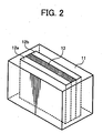
- Fig. 1 is a schematic view illustrating an embodiment of the vibrating sieve with an ultrasonic oscillator for use in the classifying method of the present invention.
- numeral 1 is a vibrating sieve
- 2 is a cylindrical container
- 3 is a spring
- 4 is a base (support)
- 5 is two or more closely layered meshes and the lowermost mesh has large openings
- 6 is a resonant member (having the shape of a ring in this embodiment)
- 7 is a high-frequency current cable
- 8 is a converter
- 9 is a ring-shaped frame.
- a high-frequency current is provided to the converter 8 through the cable 7.
- the high-frequency current provided to the converter 8 is converted to an ultrasonic vibration.
- the ultrasonic vibration generated at the converter 8 vertically vibrates the resonant member 6 on which the converter 8 is fixed and the junctual ring-shaped frame 9.
- the vibration of the resonant member 6 vertically vibrates the meshes 5 fixed on the resonant member 6 and frame 9.
- a marketed vibrating sieve with an ultrasonic oscillator such as ULTRASONIC from Koei Sangyo Co., Ltd. can be used.
- any particles which are not at all classified, or classified by air or mechanically can be classified by the classifier of the present invention. Further, according to the particle diameter distribution, fine particles, coarse particles or both of them can be classified.
- the classifier of the present invention preferably classifies the coarse particles because of having a sharper particle diameter distribution than classifying methods such as an air classifying method and being able to collect particles having a desired particle diameter at a high yield.
- the uppermost mesh can be formed with woven thin lines or holes can be formed thereon by a laser or by etching.
- a fibrous mesh woven with various materials is preferably used.
- the uppermost mesh is formed of a material having a bending elasticity of from 1 to 10 GPa.
- the openings of the uppermost mesh are slightly transformed by a vibration transmitted from the lowermost mesh to prevent the mesh from being clogged, and which improves efficiency of the classification.
- the openings thereof are less transformed and the mesh tends to be clogged, resulting in deterioration of efficiency of the classification.
- the uppermost mesh absorbs the vibration of the lowermost mesh and the openings of the uppermost mesh are largely transformed, resulting in deterioration of efficiency of the classification.
- the materials of the uppermost mesh are not particularly limited, provided they have a bending elasticity of from 1 to 10 GPa, but they are preferably resins because of their low production costs.
- the production costs per unit area of a nylon mesh having an opening of about 20 ⁇ m is about 1/20 of a stainless steel mesh.
- the uppermost mesh having small openings and a moderate elasticity has a short life and is not suitable on its own for the mesh for an ultrasonic vibrating sieve because of its insufficient strength when having no mesh beneath. Therefore, when used together with a mesh formed of a material having a bending elasticity of from 50 to 500 GPa and sufficient strength beneath, the ultrasonic vibrating sieve has better classifying preciseness and efficiency.
- the methods of preparation and materials of the resin mesh are not particularly limited except for the bending elasticity.
- Known resins such as a nylon resin, a polyester resin, an acrylic resin and a fluorocarbon resin can be used, provided they can form a mesh.
- the nylon resin is preferably used in terms of its durability and chemical resistance
- the polyester resin is preferably used in terms of its durability and environmental resistance.
- nylon meshes and polyester meshes such as NYTAL (RTM) and PETEX (RTM) series from Sefar Holding Inc. in Switzerland can be used.
- the mesh formed of a material having a bending elasticity not greater than 10 GPa occasionally has an insufficient strength when having no mesh beneath and is not suitable on its own for the mesh for an ultrasonic vibrating sieve.
- the double mesh has sufficient strength and durability, and the resultant vibrating sieve has better classifying preciseness and efficiency.
- the bending elasticity of the material of the mesh can be measured according to D790 of ASTM (American Society for Testing and Materials).
- the bending elasticity in the present invention is measured according to ASTM D790.
- the magnetic particulate carrier (core material) or resin-coated magnetic particulate carrier classified by the sieve of the present invention has a sharp particle diameter distribution, a weight-average particle diameter (Dw) of from 30 to 45 ⁇ m, a content of the particles having a particle diameter less than 44 ⁇ m not less than 70 % by weight, a content of the particles having a particle diameter less than 22 ⁇ m not greater than 7 % by weight, and a ratio (Dw/Dp) of the weight-average particle diameter (Dw) to a number-average particle diameter (Dp) of from 1 to 1. 30, and preferably from 1 to 1.25. Therefore, the carrier produces images having good granularity without background fouling.
- Dw weight-average particle diameter
- the carrier adherence means phenomena wherein the carrier adheres to the image portion or background of an electrostatic latent image.
- the image portion has a weaker electric field intensity than the background because a toner is developed, the image portion has less carrier adherence.
- Dw weight-average particle diameter
- the carrier has a weight-average particle diameter (Dw) of from 22 to 32 ⁇ m
- Dw weight-average particle diameter
- the carrier has a content of the particles having a particle diameter less than 36 ⁇ m of from 90 to 100 % by weight, a content of the particles having a particle diameter less than 20 ⁇ m not greater than 7 % by weight and a ratio (Dw/Dp) of the weight-average particle diameter (Dw) to a number-average particle diameter (Dp) of from 1 to 1.30.
- the carrier When the carrier has a weight-average particle diameter (Dw) of from 22 to 32 ⁇ m, the carrier produces images having very good granularity without background fouling even when a toner concentration is high.
- Dw weight-average particle diameter
- the carrier having a content of the particles having a particle diameter less than 36 ⁇ m of from 90 to 100 % by weight, a content of the particles having a particle diameter less than 20 ⁇ m not greater than 7 %, and preferably not greater than 3 % by weight and a ratio (Dw/Dp) of the weight-average particle diameter (Dw) to a number-average particle diameter (Dp) of from 1 to 1.30, and preferably from 1 to 1.25 adheres less.
- Known magnetic materials can be used for the core material of the carrier.
- the carrier core material preferably has a magnetic moment not less than 0.05 A/m 2 g, and preferably not less than 0.06 A/m 2 g when a magnetic field of 1,000 oersted (Oe) is applied thereto.
- the maximum magnetic moment is not particularly limited, but usually about 0.15 A/m 2 g. When the magnetic moment is less than 0.05 A/m 2 g, the carrier adherence tends to occur.
- the magnetic moment can be measured as follows:
- the core material having a magnetic moment not less than 50 emu/g when a magnetic field of 1,000 Oe is applied thereto include, but are not limited to, ferromagnets such as iron and cobalt, magnetite, haematite, Li ferrite, Mn-Znferrite, Cu-Zn ferrite, Ni-Zn ferrite, Ba ferrite and Mn ferrite.
- ferromagnets such as iron and cobalt, magnetite, haematite, Li ferrite, Mn-Znferrite, Cu-Zn ferrite, Ni-Zn ferrite, Ba ferrite and Mn ferrite.
- the core material having a magnetic moment not less than 60 emu/g when a magnetic field of 1,000 Oe is applied thereto include, but are not limited to, magnetic particulate materials such as iron, magnetite, Mn-Mg ferrite and Mn ferrite.
- the resin-coatedparticulate carrier foruse in the present invention can be prepared by forming resin layers on the above-mentioned core materials.
- Known resins for use in preparation of a carrier can be used for forming the resin layer.
- the following resins can be used alone or in combination in the present invention.
- Silicone resins such as polystyrene, chloropolystyrene, poly- ⁇ -methylstyrene, styrene-chlorostyrene copolymers, styrene-propylene copolymers; styrene-butadiene copolymers, styrene-vinylchloride copolymers, styrene-vinylacetate copolymers; styrene-maleic acid copolymers, styrene-esteracrylate copolymers (styrene-methylacrylate copolymers, styrene-ethylacrylate copolymers, styrene-butylacrylate copolymers, styrene-octylacrylate copolymers, styrene-phenylacrylate copolymers, etc.) and styrene-ester
- silicone resins include, but are not limited to, Kr271, KR272, KR282, KR252, KR255 and KR152 from Shin-Etsu Chemical Co., Ltd.; and SR2400, SR2406 from DowCorning Toray Silicone Co., Ltd.
- modified-silicone resins include, but are not limited to, epoxy-modified silicone, acrylic-modified silicone, phenol-modified silicone, urethane-modified silicone, polyester-modified silicone and alkyd-modified silicone.
- Known methods such as a spray dry coating method, a dip coating method and a powder coating method can be used to form a resin layer on the surface of a particulate carrier core material.
- a fluidized bed coater is effectively used to form a uniform coated layer.
- the resin layer formed on the particulate carrier core material preferably has a thickness of from 0.02 to 1 ⁇ m, and more preferably from 0.03 to 0.8 ⁇ m.
- the carrier can be a resin dispersion carrier, wherein a magnetic powder is dispersed in known resins such as a phenol resin, an acrylic resin and a polyester resin.
- the carrier has a resistivity not greater than 1.0x10 15 ⁇ cm, and preferably not greater than 1.0x10 14 ⁇ cm.
- the minimum resistivity is not particularly limited, but usually about 1.0x10 10 ⁇ cm.
- the resistivity of the carrier is higher than 1.0x10 15 ⁇ cm, the carrier adherence tends to occur.
- the resistivity is within the above-mentioned range, the carrier adherence is difficult to occur and developability of the carrier increases to produce images having sufficient image density.
- the carrier resistivity can be measured by the following method.
- a carrier 13 is filled in a cell 11 formed of a fluorocarbon resin container containing electrodes 12a and 12b having a distance therebetween of 2 mm and a surface area 2x4 cm, a DC voltage of 100 V is applied therebetween and a DC resistivity is measured by a High Resistance Meter 4329A from Hewlett-Packard Development Company, L.P. to determine the electric resistivity Log R (Qcm).
- the resistivity of the carrier can be controlled by controlling the resistivity and thickness of a coated resin layer on the particulate core material, or adding an electroconductive fine powder to the coated resin layer.
- the electroconductive fine powder include, but are not limited to, metal or metal oxide powders such as electroconductive ZnO and Al; SnO 2 prepared by various methods or doped with various atoms; borides such as TiB 2 , ZnB 2 and MoB 2 ; SiO 2 ; electroconductive polymers such as polyacetylene, polyparaphenylene, poly(paraphenylenesulphide)polypyrrole and polyethylene; and carbon blacks such as furnace black, acetylene black and channel black.
- metal or metal oxide powders such as electroconductive ZnO and Al
- SnO 2 prepared by various methods or doped with various atoms
- borides such as TiB 2 , ZnB 2 and MoB 2
- SiO 2 silicon oxide
- electroconductive polymers such as polyacetylene, polyparaphenylene, poly(paraphenylenesulphide)polypyrrole and polyethylene
- carbon blacks such as furnace black, acetylene black and channel black.
- electroconductive fine powders can uniformly be dispersed in a disperser using media such as ball mill and beads mill or a stirrer equipped with a blade rotating at a high-speed after being included in a solvent or a resin solution for coating.
- the resin-coated magnetic particles prepared by the classifying method of the present invention are mixed with a toner to prepare a developer, and the toner will be explained.
- the toner preferably includes a thermoplastic binder resin as a main component, a colorant, a particulate material, a charge controlling agent, a release agent, etc., and known toners can be used.
- the toner may be an amorphous or a spherical toner prepared by various methods such as polymerisation methods and granulation methods.
- either a magnetic or a non-magnetic toner can be used.
- the weight-average particle diameter Dw of the carrier or the core material thereof is determined according to the particle diameter distribution measured on a number standard (a relation ship between the number frequency and particle diameter).
- the channel is a length equally dividing a scope of particle diameters in the particle diameter distribution, and the length is 2 ⁇ m for the carrier of the present invention.
- the representative diameter present in each channel is a minimum particle diameter of the particles present in each channel.
- the number-average particle diameter Dp of the carrier or the core material thereof is determined according to the particle diameter distribution measured on a number standard.
- the carrier particle size distribution is suitably measured by laser diffraction.
- a particle size analyzer Microtrac HRA 9320-X100 from Honeywell, Inc. is used to measure a particle diameter distribution of the carrier under the following conditions:
- the particle diameter distribution of the toner is measured by Coulter counter.
- the carrier having a sharp particle diameter distribution to be produced according to the present invention may include a magnetic core material and a resin-coated magnetic particulate material, and therefore embodiments of the classifying method of the present invention include the following three cases:
- the resin-coated magnetic particulate material as a carrier has good granularity and is difficult to adhere.
- Polyester resin 100 Carnauba wax 5 Carbon black #44 from Mitsubishi Chemical Corp. 9 Compound including chrome azo T-77 from HODOGAYA CHEMICAL CO., LTD. 3
- the kneaded mixture was cooled and crushed by a cutter mill to prepare a crushed material, the crushed material was pulverized to prepare a pulverized material and the pulverized material was classified by a wind force classifier to prepare a mother toner having an weight-average particle diameter of 5.6 ⁇ m.
- a particulate hydrophobic silica R972 from Nippon Aerosil Co. , Ltd.
- 100 parts of the mother toner were mixed by a HENSCHEL mixer to prepare a toner a.
- silicone resin SR2411 from Dow Corning Toray Silicone Co., Ltd.
- carbon KETJENBLACK EC-600JD from Lion Corp.
- an amino silane coupling agent (NH2(CH2)3Si(OCH3)) of 3 % per 100 % of the solid content of the silicone resin was mixed with the dispersion to prepare a dispersion.
- the dispersion was coatedon 5 kgs of a carrier core material I in Table 1 by a fluidized bed coater at 30 g/min in an atmosphere of 100 °C, and was further heated at 200 °C for 2 hrs to prepare a resin-coated carrier A having a resin layer thickness of 0.31 ⁇ m.
- the resin layer thickness was controlled by an amount of the coating liquid, i.e., the dispersion.
- the particle diameter distribution of the carrier A is shown in Tables 2-1 and 2-2.
- the carrier core material I in Table 1 was fed onto a stainless mesh at 0.5 kgs/min. to classify the carrier core material I.
- a vibrating sieve used has a constitution generally as shown in Fig. 1 and is a sieving apparatus 1, wherein a resonant ring 6 having a transducer 8 generating an ultrasonic wave having a frequency of 36 kHz as a resonant member directly contacts a stainless steel mesh 5 (635 mesh) having a diameter of 70 cm, supported by a frame 9.
- the mesh is a single mesh (not according to the invention).
- the stainless steel mesh 5 is located in a cylindrical container 2 supported by a base 4 through a spring 3.
- a vibration motor (not shown) is located in the base 4, which transmits a high-frequency current to the transducer 8 installed at the resonant ring 6 through a cable 7 to generate the ultrasonic wave.
- the resonant ring 6 is vibrated by the ultrasonic wave, which vertically vibrates the whole mesh 5.
- the carrier core material fed onto the stainless steel mesh 5 in the cylindrical container 2 is sieved to remove undesired fine particles thereof to the bottom of the cylindrical container 2 beneath the mesh 5.
- the particle diameter distribution of the carrier core material II is shown in Table 1.
- the particle diameter distribution of the carrier B is shown in Tables 2-1 and 2-2.
- the mesh was scarcely clogged in a short time, but gradually clogged after classified for a long time and the mesh needed cleaning when 1, 000 kgs of the core material were classified (classified for 30 hrs).
- the mesh was cleaned every time when 500 kgs thereof were classified, but when 2,000 kgs were classified, the mesh broke and needed a replacement.
- the replacement of the mesh (635 mesh) cost as much as not less than 100 yen/kg.
- a vibrating sieve according to the invention as shown in Fig. 1 , is now used, having a stainless steel mesh having openings of 104 ⁇ m (150 mesh) was located underneath, and a nylon mesh having openings of 20 ⁇ m closely layered thereon.
- a material (nylon-66) used for the nylon mesh has a bending elasticity of 2.8 GPa.
- the stainless mesh underneath directly receives a vibration from the ultrasonic transducer, and the ultrasonic vibration is efficiently transmitted to the nylon mesh closely located thereon and the nylon mesh classifies the particles.
- the carrier core material I in Table 1 was fed onto the nylon mesh at 0.5 kgs/min to classify the carrier core material I using the vibration sieve just as classified in Carrier Preparation Example 2 to prepare a carrier core material III.
- the particle diameter distribution of the carrier C is shown in Tables 2-1 and 2-2.
- the nylon mesh was scarcely clogged in a short time, but gradually clogged after classified for a long time, and needed cleaning when 1,500 kgs of the core material were classified.
- the nylon mesh was cleanable by washing, but since its classifying preciseness deteriorated, the nylon mesh was replaced with a new one.
- the replacement of the nylon mesh (the stainless mesh underneath does not need a replacement) cost as low as 1/10 or less than that of using only a stainless mesh.
- Amaterial (polyethersulphone) usedforthepolyestermesh has a bending elasticity of 2.6 GPa.
- the particle diameter distribution of the carrier D is shown in Tables 2-1 and 2-2.
- the polyester mesh needed cleaning when 2,000 Kgs of the core material were classified, and was replaced with a new one.
- the feeding speed of the carrier core material was reduced because of its very low passage rate, i.e., operation efficiency per classifying time.
- a material (ultra-polymer polyethylene) used for the ultra-polymer polyethylene mesh has a bending elasticity of 0.9 GPa.
- the particle diameter distribution of the carrier E is shown in Tables 2-1 and 2-2.
- the polyethylene mesh needed cleaning when 2, 000 kgs of the core material were classified, and was replaced with a new one.
- the replacement of the polyethylene mesh (the stainless mesh underneath does not need a replacement) cost higher than that of the nylon mesh, but lower than that of using only the stainless mesh.
- the procedure for preparation of the carrier core material III in Carrier preparation Example 3 was repeated except for using a reinforced polyester mesh including a glass fiber (hereinafter referred to as GF) of 30 % and having openings of 21 ⁇ m to prepare a carrier core material VI.
- GF glass fiber
- a material (reinforced polyethylene terephthalate including a GF of 30 %) used for the reinforced polyester mesh including a GF of 30 % has a bending elasticity of 11.0 GPa.
- the particle diameter distribution of the carrier F is shown in Tables 2-1 and 2-2.
- the polyester mesh needed cleaning when 1,200 kgs of the core material were classified, and was replaced with a new one.
- the replacement of the reinforced polyester mesh including a GF of 30 % does not need a replacement) cost higher than that of the nylon mesh, but lower than that of using only the stainless mesh.
- the particle diameter distribution of the carrier G is shown in Tables 2-1 and 2-2.
- the mesh Since the particle fluidity is better than the core material, the mesh was less clogged than the mesh which sieved the core material. However, the mesh needed cleaning when 2,000 kgs of the core material were classified, and was replaced with a new one (the stainless mesh underneath does not need a replacement).
- the particle diameter distribution of the carrier H is shown in Tables 2-1 and 2-2.
- the carrier having a large particle diameter was removed, and the resin-coated carrier H was collected on the bottom of the cylindrical container 2 beneath the stainless mesh 5.
- the particle diameter distribution of the carrier I is shown in Tables 2-1 and 2-2.
- the particle diameter distribution of the carrier J is shown in Tables 2-1 and 2-2.
- the mesh needed cleaning when 2 , 000 kgs of the core material were classified, and was replaced with a new one (the stainless mesh underneath does not need a replacement).
- the replacement of the mesh cost as low as 1/10 or less than that of using only a stainless mesh.
- Images were produced by a digital color copier and printer Imagio Color 4000 from Ricoh Company, Ltd. using the developer to test the granularity of the images and carrier adherence under the following conditions:
- Table 1 Dw Dn Wt. % of 22 ⁇ m or less wt. % of 20 ⁇ m or less wt. % of 44 ⁇ m or less wt.
- Carrier A 36.7 27.3 14.1 7.8 88.6 60.4 1.34 0.31
- Cacrier B 37.4 31.8 1.8 0.1 80.0 53.6 1.18 0.30
- Carrier C 37.8 32.4 1.6 0.1 80.1 54.5 1.17 0.30
- Carrier D 37.9 32.1 1.4 0.1 79.3 53.2 1.19 0.30
- Carrier B 38.1 32.7 1.3 0.0 80.3 53.4 1.17 0.31
- Carrier G 37.4 32.5 1.2 0.0 80.3 54.6 1.15 0.30 carrier H 34.2 30.3 1.8 0.0 95.2 70.2 1.13 0.30
- Carrier I 26.8 19.6 31.2 16.3 97.8 96.5 1.37 0.30
Landscapes
- Physics & Mathematics (AREA)
- General Physics & Mathematics (AREA)
- Developing Agents For Electrophotography (AREA)
- Combined Means For Separation Of Solids (AREA)
Claims (11)
- Vibrationssieb (1) zur Klassifizierung eines partikulären Materials, das aufweist:einen Schwingungserzeuger, der einen Ultraschallwandler (8) aufweist; undmindestens zwei Siebe (5), die miteinander schichtartig und auf dem Ultraschallwandler (8) angeordnet sind,wobei ein unterstes Sieb, das eine Schwingung vom Ultraschallwandler (8) aufnimmt, die Schwingung auf ein oberstes Sieb überträgt, um das darauf zugeführte partikuläre Material zu klassifizieren, wobei das unterste Sieb große Öffnungen und das oberste Sieb kleine Öffnungen aufweist, dadurch gekennzeichnet, dass das oberste Sieb aus einem Material mit einer Biegeelastizität von 1 bis 10 GPa gebildet wird.
- Vibrationssieb (1) nach Anspruch 1, bei dem das oberste Sieb ein Harzsieb ist
- Vibrationssieb (1) nach Anspruch 2, bei dem das Harzsieb mit einem Nylonfaden gewebt wird.
- Vibrationssieb (1) nach Anspruch 2, bei dem das Harzsieb mit einem Polyesterfaden gewebt wird.
- Vibrationssieb (1) nach einem der Ansprüche 1 bis 4, das außerdem ein Resonanzelement (6) aufweist, wobei das Resonanzelement (6) auf den mindestens zwei Sieben (5) befestigt ist, die Schwingung aufnimmt und die Schwingung auf das oberste Sieb überträgt.
- Vibrationssieb (1) nach einem der Ansprüche 1 bis 5, bei dem das vibrationssieb (1) sowohl feine Teilchen als auch grobe Teilchen in einer Teilchenduxchmesserverteilung klassifiziert.
- Verfahren zur Klassifizierung, eines partikulären Materials, das die folgenden Schritte aufweist:Übertragen einer Schwingung mit einem Schwingungserzeuger (8), der einen Ultraschallwandler aufweist, auf ein unterstes Sieb der mindestens zwei Siebe (5), die miteinander schichtartig und auf dem Ultaschallwandler (8) angeordnet sind; undÜbertragen der Schwingung auf ein oberste Sieb, um das darauf zugeführte partikuläre Material zu klassifizierten, wobei das unterste Sieb große Öffnungen und das oberste Sieb kleine Öffnungen aufweist, dadurch gekennzeichnet, dass das oberste Sieb aus einem Material mit einer Biegeelastizität von 1 bis 10 GPa gebildet wird.
- Verfahren nach Anspruch 7, das außerdem ein Resonanzelement (6) aufweiset, wobei das ltesonanzelement (6) auf den mindestens zwei Sieben (5) befestigt ist, die Schwingung aufnimmt und die Schwingung auf das oberste Sieb überträgt.
- Verfahren zur Herstellung eines Magnetkeromaterials, das den folgenden Schritt aufweist:Klassifizieren des Magnetkemmaterials mit dem Vibrationssieb (1) nach einem der Ansprüche 1 bis 6.
- Verfahren zur Herstellung eines Trägermaterials, das aus einem harzbeschichteten Magnetkernmaterial gebildet wird, das den folgenden Schritt aufweist:Klassifizieren des harzbeschichteten Magnetkernmaterials mit dem Vibrationssieb (1) nach einem der Ansprüche 1 bis 6.
- Verfahren nach Anspruch 10, bei dem das harzbeschichtete Magnetkermmaterial das Magnetkemmaterial nach Anspruch 9 aufweist.
Priority Applications (1)
| Application Number | Priority Date | Filing Date | Title |
|---|---|---|---|
| EP11001021.2A EP2324934B1 (de) | 2003-11-18 | 2004-11-18 | Träger, Entwickler der den Träger verwendet und Prozesskartusche die den Entwickler verwendet |
Applications Claiming Priority (4)
| Application Number | Priority Date | Filing Date | Title |
|---|---|---|---|
| JP2003388599 | 2003-11-18 | ||
| JP2003388599 | 2003-11-18 | ||
| JP2004206102 | 2004-07-13 | ||
| JP2004206102 | 2004-07-13 |
Related Child Applications (1)
| Application Number | Title | Priority Date | Filing Date |
|---|---|---|---|
| EP11001021.2 Division-Into | 2011-02-08 |
Publications (3)
| Publication Number | Publication Date |
|---|---|
| EP1535670A2 EP1535670A2 (de) | 2005-06-01 |
| EP1535670A3 EP1535670A3 (de) | 2008-03-05 |
| EP1535670B1 true EP1535670B1 (de) | 2011-06-15 |
Family
ID=34467817
Family Applications (2)
| Application Number | Title | Priority Date | Filing Date |
|---|---|---|---|
| EP11001021.2A Expired - Lifetime EP2324934B1 (de) | 2003-11-18 | 2004-11-18 | Träger, Entwickler der den Träger verwendet und Prozesskartusche die den Entwickler verwendet |
| EP04257158A Expired - Lifetime EP1535670B1 (de) | 2003-11-18 | 2004-11-18 | Vibrationssieb und Verfahren zur Klassifizierung eines partikulären Material |
Family Applications Before (1)
| Application Number | Title | Priority Date | Filing Date |
|---|---|---|---|
| EP11001021.2A Expired - Lifetime EP2324934B1 (de) | 2003-11-18 | 2004-11-18 | Träger, Entwickler der den Träger verwendet und Prozesskartusche die den Entwickler verwendet |
Country Status (2)
| Country | Link |
|---|---|
| US (2) | US7763410B2 (de) |
| EP (2) | EP2324934B1 (de) |
Cited By (2)
| Publication number | Priority date | Publication date | Assignee | Title |
|---|---|---|---|---|
| CN111592286A (zh) * | 2020-05-18 | 2020-08-28 | 杭州元成规划设计集团有限公司 | 一种具有良好生物亲和性的生态护岸材料 |
| CN111702163A (zh) * | 2020-05-29 | 2020-09-25 | 同济大学 | 一种3d打印金属粉末振动筛 |
Families Citing this family (32)
| Publication number | Priority date | Publication date | Assignee | Title |
|---|---|---|---|---|
| JP4608393B2 (ja) * | 2004-09-10 | 2011-01-12 | 株式会社リコー | 電子写真用現像剤及び電子写真現像方法、プロセスカートリッジ |
| JP2006293266A (ja) * | 2005-03-16 | 2006-10-26 | Ricoh Co Ltd | 静電潜像現像用キャリア、これを用いた静電潜像現像剤、画像形成方法、及びプロセスカートリッジ |
| JP4728903B2 (ja) * | 2005-08-25 | 2011-07-20 | 株式会社リコー | キャリア及び現像剤、並びに画像形成方法、画像形成装置及びプロセスカートリッジ |
| JP4861233B2 (ja) * | 2006-04-17 | 2012-01-25 | 株式会社リコー | 電子写真現像剤キャリア用芯材粒子及びその製造方法、並びに電子写真用現像剤及び画像形成方法 |
| WO2007136472A1 (en) * | 2006-05-18 | 2007-11-29 | Dow Global Technologies Inc. | Use of special screens in the preparation of cellulose powder |
| DE102006037638B4 (de) * | 2006-08-10 | 2014-05-22 | Artech Systems Ag | Verfahren und Vorrichtung zum Sieben, Klassieren, Filtern oder Sortieren trockener fester Stoffe oder fester Stoffe in Flüssigkeiten |
| DE102006047591B4 (de) * | 2006-08-10 | 2015-08-13 | Artech Systems Ag | Vorrichtung und Verfahren zum Sieben, Klassieren, Filtern oder Sortieren trockener fester Stoffe oder fester Stoffe in Flüssigkeiten |
| JP5333882B2 (ja) * | 2006-09-14 | 2013-11-06 | 株式会社リコー | 電子写真用現像剤 |
| DE102006047592C5 (de) | 2006-10-05 | 2019-01-10 | Artech Systems Ag | Vorrichtung zur Anregung eines in einem Siebrahmen eingefassten Siebgewebes mittels Ultraschall |
| JP2008102394A (ja) * | 2006-10-20 | 2008-05-01 | Ricoh Co Ltd | キャリア、補給用現像剤、現像装置内現像剤、現像剤補給装置、画像形成装置、プロセスカートリッジ |
| JP4817389B2 (ja) * | 2007-01-15 | 2011-11-16 | 株式会社リコー | 画像形成装置、プロセスカートリッジ、画像形成方法及び電子写真用現像剤 |
| US20080213684A1 (en) * | 2007-01-18 | 2008-09-04 | Masashi Nagayama | Carrier for electrophotographic developer, developer, image forming method, image forming apparatus, and process cartridge |
| EP1965261B1 (de) * | 2007-03-02 | 2016-11-09 | Ricoh Company, Ltd. | Toner zur Entwicklung eines elektrostatischen Bildes, Verfahren zur Herstellung des Toners, Bilderzeugungsverfahren, Bilderzeugungsvorrichtung und Prozesskartusche mit dem Toner |
| US8679719B2 (en) | 2007-03-16 | 2014-03-25 | Ricoh Company, Ltd. | Carrier, developer and electrophotographic developing method and image forming method |
| JP2009064003A (ja) * | 2007-08-09 | 2009-03-26 | Ricoh Co Ltd | 画像形成装置 |
| JP5429594B2 (ja) | 2007-09-13 | 2014-02-26 | 株式会社リコー | 画像形成方法、画像形成装置並びにプロセスカートリッジ及びそのための電子写真現像剤並びに現像剤用キャリア |
| EP2067534A1 (de) * | 2007-12-05 | 2009-06-10 | Artech Systems AG | Siebsystem mit rohrförmigem Sieb und Verfahren zum Betrieb eines Siebsystems mit rohrförmigem Sieb |
| JP5434412B2 (ja) * | 2008-09-17 | 2014-03-05 | 株式会社リコー | 静電潜像現像用キャリア、二成分現像剤、補給用現像剤、及びプロセスカートリッジ、並びに画像形成方法 |
| JP5454081B2 (ja) | 2008-11-12 | 2014-03-26 | 株式会社リコー | キャリア |
| JP5212038B2 (ja) * | 2008-11-17 | 2013-06-19 | 株式会社リコー | 電子写真用トナーの製造方法、トナー製造用篩装置、及びトナーの再生方法 |
| US8211610B2 (en) | 2009-03-18 | 2012-07-03 | Ricoh Company Limited | Carrier for use in developer developing electrostatic image, developer using the carrier, and image forming method and apparatus and process cartridge using the developer |
| JP5553229B2 (ja) * | 2009-09-14 | 2014-07-16 | 株式会社リコー | 静電潜像用キャリア、及び静電潜像用現像剤 |
| JP5534409B2 (ja) * | 2010-01-13 | 2014-07-02 | 株式会社リコー | 静電荷像現像用キャリア、現像剤、現像装置、画像形成装置、画像形成方法及びプロセスカートリッジ |
| JP5598184B2 (ja) | 2010-03-17 | 2014-10-01 | 株式会社リコー | 静電潜像現像剤用キャリア |
| JP5729170B2 (ja) | 2010-08-02 | 2015-06-03 | 株式会社リコー | 現像方法及び画像形成方法 |
| JP5754215B2 (ja) | 2011-04-01 | 2015-07-29 | 株式会社リコー | 画像形成方法、画像形成装置、及びプロセスカートリッジ |
| US9205458B2 (en) * | 2013-07-17 | 2015-12-08 | Toyota Motor Engineering & Manufacturing North America, Inc. | Method and apparatus for sorting fibers |
| JP2015184570A (ja) * | 2014-03-25 | 2015-10-22 | 富士ゼロックス株式会社 | 静電荷像現像用キャリア、静電荷像現像剤、現像剤カートリッジ、プロセスカートリッジ、及び画像形成装置 |
| TWI725041B (zh) * | 2015-07-23 | 2021-04-21 | 美商美國禮來大藥廠 | 用於治療神經母細胞瘤及/或軟組織肉瘤之chk1/2抑制劑 |
| JP6627965B2 (ja) | 2016-03-17 | 2020-01-08 | 株式会社リコー | 静電潜像現像剤用キャリア、二成分現像剤、補給用現像剤、画像形成装置、及びトナー収容ユニット |
| CN109625548B (zh) * | 2018-12-08 | 2020-09-11 | 绍兴市卓诚新材料有限公司 | 可实现散装与袋装同时转移的转移筒装置 |
| CN114572606B (zh) * | 2022-04-14 | 2022-11-25 | 江苏松上科技有限公司 | 一种聚丙烯生产用供料装置 |
Family Cites Families (36)
| Publication number | Priority date | Publication date | Assignee | Title |
|---|---|---|---|---|
| US4016131A (en) * | 1975-04-04 | 1977-04-05 | Vitrofil Corporation | Preparation of unsaturated polyester compositions |
| US4417978A (en) * | 1979-09-24 | 1983-11-29 | Guth Karl V L | Centrifugal screening device |
| DE3312741C2 (de) | 1982-04-08 | 1985-07-04 | Ricoh Co., Ltd., Tokio/Tokyo | Trägerteilchen für elektrostatographische Entwickler und deren Verwendung |
| JPS61180247A (ja) | 1985-02-06 | 1986-08-12 | Ricoh Co Ltd | 静電潜像用現像剤 |
| JP2750853B2 (ja) | 1986-11-20 | 1998-05-13 | 株式会社リコー | 静電潜像現像用トナー |
| EP0311687B1 (de) * | 1987-02-17 | 1992-01-22 | Nihon Tokushu Orimono Co. Ltd. | Gittergewebe für filmdruck |
| JP2739982B2 (ja) | 1988-04-11 | 1998-04-15 | 株式会社リコー | 静電荷像現像用トナー |
| JP2815613B2 (ja) | 1989-03-24 | 1998-10-27 | 株式会社リコー | 静電荷像現像用トナー |
| US5085965A (en) | 1989-03-27 | 1992-02-04 | Ricoh Company, Ltd. | Negative toner for developing latent electrostatic images |
| JP3003936B2 (ja) | 1989-06-02 | 2000-01-31 | 株式会社リコー | 電子写真用トナー |
| JPH04271359A (ja) | 1991-02-27 | 1992-09-28 | Ricoh Co Ltd | 乾式現像剤 |
| US5429752A (en) * | 1993-02-16 | 1995-07-04 | Presby; David W. | Means for precipitating out suspended solids in septic tank liquids |
| EP0652810B2 (de) * | 1993-05-26 | 2002-07-03 | Telsonic Ag | Vorrichtung und verfahren zum sieben, klassieren, sichten, filtern oder sortieren von stoffen |
| US5398816A (en) | 1993-07-20 | 1995-03-21 | Sweco, Incorporated | Fine mesh screening |
| US6296826B1 (en) * | 1994-12-30 | 2001-10-02 | Shin-Etsu Quartz Products Co., Ltd. | Method for the preparation of vitrified silica particles |
| DE19518358C1 (de) | 1995-05-19 | 1996-12-19 | Reimelt Dietrich Kg | Siebeinrichtung |
| US6845868B1 (en) * | 1999-03-28 | 2005-01-25 | Vibtec Engineering Ltd. | Multifrequency vibratory separator system, a vibratory separator including same, and a method of vibratory separation of solids |
| JP3767846B2 (ja) | 1999-05-28 | 2006-04-19 | 株式会社リコー | 静電荷像現像用トナー及び画像形成方法 |
| US6319646B1 (en) | 1999-09-16 | 2001-11-20 | Ricoh Technology Research, Inc. | Carrier for electrophotographic developer, method for manufacturing, developer, container including the developer, and image forming apparatus using the developer wherein the carrier satisfies the relationship 1.0≦C2/C1≦1.3 |
| JP3883379B2 (ja) | 1999-11-17 | 2007-02-21 | 株式会社リコー | 電子写真用現像剤 |
| US6472118B1 (en) | 1999-11-17 | 2002-10-29 | Ricoh Company, Ltd | Carrier for developer for electrophotography |
| US6489073B2 (en) | 2000-01-14 | 2002-12-03 | Ricoh Company, Ltd. | Method and device for developing electrostatic latent images |
| DE60120556T2 (de) | 2000-05-23 | 2007-06-06 | Ricoh Co., Ltd. | Zwei-Komponenten-Entwickler, ein mit diesem Entwickler gefüllter Behälter, und Bilderzeugungsvorrichtung |
| JP3841341B2 (ja) | 2001-03-07 | 2006-11-01 | 株式会社リコー | 静電潜像現像方法 |
| US20020187252A1 (en) * | 2001-03-22 | 2002-12-12 | Jaspreet Singh | High superabsorbent content webs and a method for making them |
| JP2002296846A (ja) * | 2001-03-30 | 2002-10-09 | Powdertech Co Ltd | 電子写真現像剤用キャリア及び該キャリアを用いた現像剤 |
| EP1255168B1 (de) * | 2001-05-01 | 2005-12-14 | Ricoh Company, Ltd. | Träger für elektrophotographische Entwickler |
| CA2377049C (en) * | 2001-10-29 | 2007-01-30 | Kotaro Nakano | Sieving device |
| JP3946518B2 (ja) | 2001-12-28 | 2007-07-18 | 株式会社リコー | 画像形成用カラートナー、画像形成装置及びトナー容器 |
| US6735409B2 (en) | 2002-01-11 | 2004-05-11 | Ricoh Company, Ltd. | Process for developing, image-forming apparatus, and image-forming process cartridge |
| JP3891480B2 (ja) | 2002-03-22 | 2007-03-14 | 株式会社リコー | 静電潜像現像用キャリア、それを用いた静電潜像現像剤および静電潜像現像方法 |
| US7052815B2 (en) | 2002-05-24 | 2006-05-30 | Ricoh Company, Limited | Color toner for developing electrostatic images, toner container containing the color toner, and image forming method and apparatus using the color toner |
| US6939654B2 (en) | 2002-12-06 | 2005-09-06 | Ricoh Company, Ltd. | Carrier and developer for developing latent electrostatic images |
| JP2004206102A (ja) | 2002-12-12 | 2004-07-22 | Dainippon Printing Co Ltd | 配向膜組成物及びそれを用いた光学素子の製造方法 |
| US20050058822A1 (en) * | 2003-08-04 | 2005-03-17 | Ittel Steven Dale | Fiber-reinforced thermoplastic matrices |
| DE602004020235D1 (de) * | 2003-08-29 | 2009-05-07 | Battelle Memorial Institute | Konstruktionsverbundwerkstoffe mit erhöhten elastizitätsmodulen |
-
2004
- 2004-11-01 US US10/977,013 patent/US7763410B2/en not_active Expired - Fee Related
- 2004-11-18 EP EP11001021.2A patent/EP2324934B1/de not_active Expired - Lifetime
- 2004-11-18 EP EP04257158A patent/EP1535670B1/de not_active Expired - Lifetime
-
2007
- 2007-11-20 US US11/943,404 patent/US20080073252A1/en not_active Abandoned
Cited By (2)
| Publication number | Priority date | Publication date | Assignee | Title |
|---|---|---|---|---|
| CN111592286A (zh) * | 2020-05-18 | 2020-08-28 | 杭州元成规划设计集团有限公司 | 一种具有良好生物亲和性的生态护岸材料 |
| CN111702163A (zh) * | 2020-05-29 | 2020-09-25 | 同济大学 | 一种3d打印金属粉末振动筛 |
Also Published As
| Publication number | Publication date |
|---|---|
| EP2324934B1 (de) | 2013-04-24 |
| US20080073252A1 (en) | 2008-03-27 |
| US7763410B2 (en) | 2010-07-27 |
| EP2324934A1 (de) | 2011-05-25 |
| EP1535670A2 (de) | 2005-06-01 |
| EP1535670A3 (de) | 2008-03-05 |
| US20050158643A1 (en) | 2005-07-21 |
Similar Documents
| Publication | Publication Date | Title |
|---|---|---|
| EP1535670B1 (de) | Vibrationssieb und Verfahren zur Klassifizierung eines partikulären Material | |
| EP1847884B1 (de) | Elektrofotografischer Entwickler und Träger dafür, Kernmaterialteilchen für den Träger des elektrofotografischen Entwicklers und Herstellungsverfahren dafür sowie Bilderzeugungsverfahren | |
| KR101244051B1 (ko) | 전자사진 현상제용 캐리어의 제조 방법, 전자사진 현상제용 캐리어 및 전자사진용 현상제 | |
| US9958809B2 (en) | Magnetic carrier | |
| EP2085828B1 (de) | Zweikomponenten-Entwickler und Bilderzeugungsverfahren mit den Entwickler | |
| JP4608393B2 (ja) | 電子写真用現像剤及び電子写真現像方法、プロセスカートリッジ | |
| JP4223976B2 (ja) | 電子写真現像剤用キャリア、および現像方法 | |
| JP2001209215A (ja) | 電子写真現像剤用キャリア | |
| JP2006039445A (ja) | 電子写真現像剤用キャリアおよび現像方法 | |
| JP4668586B2 (ja) | 電子写真キャリア用粒子の分級方法、電子写真キャリア粒子の分級用振動ふるい機、電子写真用キャリア、電子写真用現像剤、及びプロセスカートリッジ | |
| JP4484675B2 (ja) | キャリア用粒子中の異物分離方法、異物分離装置、電子写真現像剤用キャリア製造方法、抽出方法、再利用方法、画像形成方法、およびプロセスカートリッジ | |
| JP4700535B2 (ja) | 電子写真用キャリア、電子写真用現像剤、電子写真キャリア及びキャリア用芯材の製造方法 | |
| JP4520371B2 (ja) | 電子写真現像剤用キャリアの加振処理方法及び電子写真現像剤用キャリア | |
| JP2007163850A (ja) | 静電潜像現像用キャリアの製造方法及び製造装置、並びにそのキャリア | |
| JP2006171309A (ja) | 電子写真現像剤用キャリアの製造方法、電子写真現像剤用キャリア、電子写真現像剤およびプロセスカートリッジ | |
| JP5434061B2 (ja) | 電子写真現像剤用キャリアの製造方法、電子写真現像剤用キャリア、電子写真用現像剤、電子写真現像方法、プロセスカートリッジ | |
| JP2007171499A (ja) | 電子写真現像剤用キャリア、その製造方法、電子写真用現像剤、電子写真現像方法及びプロセスカートリッジ | |
| JPH0880634A (ja) | 直接静電印刷(dep)のための方法および装置 | |
| JP2010054719A (ja) | キャリア粒子製造方法、キャリア粉体及び現像剤 |
Legal Events
| Date | Code | Title | Description |
|---|---|---|---|
| PUAI | Public reference made under article 153(3) epc to a published international application that has entered the european phase |
Free format text: ORIGINAL CODE: 0009012 |
|
| 17P | Request for examination filed |
Effective date: 20041125 |
|
| AK | Designated contracting states |
Kind code of ref document: A2 Designated state(s): AT BE BG CH CY CZ DE DK EE ES FI FR GB GR HU IE IS IT LI LU MC NL PL PT RO SE SI SK TR |
|
| AX | Request for extension of the european patent |
Extension state: AL HR LT LV MK YU |
|
| PUAL | Search report despatched |
Free format text: ORIGINAL CODE: 0009013 |
|
| AK | Designated contracting states |
Kind code of ref document: A3 Designated state(s): AT BE BG CH CY CZ DE DK EE ES FI FR GB GR HU IE IS IT LI LU MC NL PL PT RO SE SI SK TR |
|
| AX | Request for extension of the european patent |
Extension state: AL HR LT LV MK YU |
|
| AKX | Designation fees paid |
Designated state(s): DE ES FR GB IT NL |
|
| 17Q | First examination report despatched |
Effective date: 20090609 |
|
| RTI1 | Title (correction) |
Free format text: VIBRATING SIEVE AND METHOD FOR CLASSIFYING A PARTICULATE MATERIAL |
|
| GRAP | Despatch of communication of intention to grant a patent |
Free format text: ORIGINAL CODE: EPIDOSNIGR1 |
|
| GRAS | Grant fee paid |
Free format text: ORIGINAL CODE: EPIDOSNIGR3 |
|
| GRAA | (expected) grant |
Free format text: ORIGINAL CODE: 0009210 |
|
| AK | Designated contracting states |
Kind code of ref document: B1 Designated state(s): DE ES FR GB IT NL |
|
| REG | Reference to a national code |
Ref country code: GB Ref legal event code: FG4D |
|
| REG | Reference to a national code |
Ref country code: DE Ref legal event code: R096 Ref document number: 602004033052 Country of ref document: DE Effective date: 20110728 |
|
| REG | Reference to a national code |
Ref country code: NL Ref legal event code: VDEP Effective date: 20110615 |
|
| PG25 | Lapsed in a contracting state [announced via postgrant information from national office to epo] |
Ref country code: NL Free format text: LAPSE BECAUSE OF FAILURE TO SUBMIT A TRANSLATION OF THE DESCRIPTION OR TO PAY THE FEE WITHIN THE PRESCRIBED TIME-LIMIT Effective date: 20110615 |
|
| PLBE | No opposition filed within time limit |
Free format text: ORIGINAL CODE: 0009261 |
|
| STAA | Information on the status of an ep patent application or granted ep patent |
Free format text: STATUS: NO OPPOSITION FILED WITHIN TIME LIMIT |
|
| 26N | No opposition filed |
Effective date: 20120316 |
|
| PG25 | Lapsed in a contracting state [announced via postgrant information from national office to epo] |
Ref country code: IT Free format text: LAPSE BECAUSE OF FAILURE TO SUBMIT A TRANSLATION OF THE DESCRIPTION OR TO PAY THE FEE WITHIN THE PRESCRIBED TIME-LIMIT Effective date: 20110615 |
|
| REG | Reference to a national code |
Ref country code: DE Ref legal event code: R097 Ref document number: 602004033052 Country of ref document: DE Effective date: 20120316 |
|
| PG25 | Lapsed in a contracting state [announced via postgrant information from national office to epo] |
Ref country code: ES Free format text: LAPSE BECAUSE OF FAILURE TO SUBMIT A TRANSLATION OF THE DESCRIPTION OR TO PAY THE FEE WITHIN THE PRESCRIBED TIME-LIMIT Effective date: 20110926 |
|
| REG | Reference to a national code |
Ref country code: DE Ref legal event code: R082 Ref document number: 602004033052 Country of ref document: DE Representative=s name: MEISSNER, BOLTE & PARTNER GBR, DE Ref country code: DE Ref legal event code: R082 Ref document number: 602004033052 Country of ref document: DE Representative=s name: MEISSNER BOLTE PATENTANWAELTE RECHTSANWAELTE P, DE |
|
| REG | Reference to a national code |
Ref country code: DE Ref legal event code: R082 Ref document number: 602004033052 Country of ref document: DE Representative=s name: MEISSNER, BOLTE & PARTNER GBR, DE |
|
| REG | Reference to a national code |
Ref country code: FR Ref legal event code: PLFP Year of fee payment: 12 |
|
| REG | Reference to a national code |
Ref country code: FR Ref legal event code: PLFP Year of fee payment: 13 |
|
| PGFP | Annual fee paid to national office [announced via postgrant information from national office to epo] |
Ref country code: FR Payment date: 20161118 Year of fee payment: 13 Ref country code: DE Payment date: 20161121 Year of fee payment: 13 Ref country code: GB Payment date: 20161122 Year of fee payment: 13 |
|
| REG | Reference to a national code |
Ref country code: DE Ref legal event code: R119 Ref document number: 602004033052 Country of ref document: DE |
|
| GBPC | Gb: european patent ceased through non-payment of renewal fee |
Effective date: 20171118 |
|
| REG | Reference to a national code |
Ref country code: FR Ref legal event code: ST Effective date: 20180731 |
|
| PG25 | Lapsed in a contracting state [announced via postgrant information from national office to epo] |
Ref country code: DE Free format text: LAPSE BECAUSE OF NON-PAYMENT OF DUE FEES Effective date: 20180602 Ref country code: FR Free format text: LAPSE BECAUSE OF NON-PAYMENT OF DUE FEES Effective date: 20171130 |
|
| PG25 | Lapsed in a contracting state [announced via postgrant information from national office to epo] |
Ref country code: GB Free format text: LAPSE BECAUSE OF NON-PAYMENT OF DUE FEES Effective date: 20171118 |