EP1535566A1 - Funduskamera - Google Patents
Funduskamera Download PDFInfo
- Publication number
- EP1535566A1 EP1535566A1 EP04028136A EP04028136A EP1535566A1 EP 1535566 A1 EP1535566 A1 EP 1535566A1 EP 04028136 A EP04028136 A EP 04028136A EP 04028136 A EP04028136 A EP 04028136A EP 1535566 A1 EP1535566 A1 EP 1535566A1
- Authority
- EP
- European Patent Office
- Prior art keywords
- image
- fundus
- anterior
- segment
- alignment
- Prior art date
- Legal status (The legal status is an assumption and is not a legal conclusion. Google has not performed a legal analysis and makes no representation as to the accuracy of the status listed.)
- Granted
Links
Images


Classifications
-
- A—HUMAN NECESSITIES
- A61—MEDICAL OR VETERINARY SCIENCE; HYGIENE
- A61B—DIAGNOSIS; SURGERY; IDENTIFICATION
- A61B3/00—Apparatus for testing the eyes; Instruments for examining the eyes
- A61B3/0016—Operational features thereof
- A61B3/0041—Operational features thereof characterised by display arrangements
- A61B3/0058—Operational features thereof characterised by display arrangements for multiple images
-
- A—HUMAN NECESSITIES
- A61—MEDICAL OR VETERINARY SCIENCE; HYGIENE
- A61B—DIAGNOSIS; SURGERY; IDENTIFICATION
- A61B3/00—Apparatus for testing the eyes; Instruments for examining the eyes
- A61B3/10—Objective types, i.e. instruments for examining the eyes independent of the patients' perceptions or reactions
- A61B3/12—Objective types, i.e. instruments for examining the eyes independent of the patients' perceptions or reactions for looking at the eye fundus, e.g. ophthalmoscopes
-
- A—HUMAN NECESSITIES
- A61—MEDICAL OR VETERINARY SCIENCE; HYGIENE
- A61B—DIAGNOSIS; SURGERY; IDENTIFICATION
- A61B3/00—Apparatus for testing the eyes; Instruments for examining the eyes
- A61B3/10—Objective types, i.e. instruments for examining the eyes independent of the patients' perceptions or reactions
- A61B3/14—Arrangements specially adapted for eye photography
- A61B3/15—Arrangements specially adapted for eye photography with means for aligning, spacing or blocking spurious reflection ; with means for relaxing
- A61B3/152—Arrangements specially adapted for eye photography with means for aligning, spacing or blocking spurious reflection ; with means for relaxing for aligning
-
- A—HUMAN NECESSITIES
- A61—MEDICAL OR VETERINARY SCIENCE; HYGIENE
- A61B—DIAGNOSIS; SURGERY; IDENTIFICATION
- A61B3/00—Apparatus for testing the eyes; Instruments for examining the eyes
- A61B3/10—Objective types, i.e. instruments for examining the eyes independent of the patients' perceptions or reactions
- A61B3/14—Arrangements specially adapted for eye photography
- A61B3/145—Arrangements specially adapted for eye photography by video means
Definitions
- the present invention relates to a fundus camera for photographing a fundus of an eye of an examinee.
- a fundus camera where rough alignment of a photographing part with an eye of the examinee is firstly performed while an image of an anterior-segment of the eye displayed on a monitor is observed, and then fine alignment with a fundus portion to be photographed is performed while an image of a fundus of the eye displayed on the monitor through display switching is observed.
- a fundus camera which projects target light for working distance detection onto a cornea of an eye of an examinee, and fine alignment is performed while a corneal reflex of the target light (a working dot) is observed along with an image of a fundus of the eye.
- An object of the invention is to overcome the problems described above and to provide a fundus camera capable of performing alignment easily and efficiently, and photographing a fundus favorably.
- a fundus camera has a photographing part in which a fundus photographing optical system is arranged, a fundus observation optical system having a first image-pickup element which picks up an image of the fundus, an anterior-segment observation optical system having a second image-pickup element which picks up an image of an anterior-segment of the eye, a display unit capable of displaying the image of the fundus picked up by the first image-pickup element and the image of the anterior-segment picked up by the second image-pickup element, and a control part which obtains information on alignment of the photographing part with the eye and decides which of the image of the fundus and the image of the anterior-segment is to be displayed on the display unit.
- Fig. 1 is a view showing a schematic configuration of a fundus camera of non-mydriasis type consistent with the preferred embodiment of the present invention.
- the fundus camera is provided with a base 1, a mobile base 2 movable in a right/left direction (hereinafter referred to as an "X-direction") and a back/forth direction (hereinafter referred to as a "Z-direction”) with reference to the base 1 through tilting operation of a joystick 4, a photographing part 3 movable in the right/left direction, an up/down direction (hereinafter referred to as a "Y-direction”), and the back/forth direction with reference to the mobile base 2 under control of a control part 81 described later, and a face support part 5 fixedly arranged on the base 1 for supporting a face (a head) of an examinee.
- X-direction a mobile base 2 movable in a right/left direction
- Z-direction back/forth direction
- a Z table movable in the Z-direction is arranged on a Y table, an X table movable in the X-direction is arranged on the Z table, and the photographing part 3 is arranged on the X table.
- the X-and Z-moving unit 7 moves the X and Z tables by their respective moving mechanisms consisting of a motor and the like to move the photographing part 3 in the X-and Z-directions.
- a Y-moving unit 6 moves the Y table by its moving mechanism consisting of a motor and the like to move the photographing part 3 in the Y-direction.
- a known mechanism may be employed.
- the photographing part 3 is moved in the Y-direction also by actuating the Y-moving unit 6 through rotational operation of the joystick 4.
- a monitor 8 for displaying an observation image and a photographed image is provided on an examiner's side of the photographing part 3.
- Fig. 2 is a view showing a schematic configuration of an optical system and a control system housed in the photographing part 3.
- the optical system generally consists of an illumination optical system 10, a fundus observation/photographing optical system 30, a focus target projection optical system 40, an alignment target projection optical system 50, an anterior-segment observation optical system 60 and a fixation target presenting optical system 70.
- the illumination optical system 10 includes an illumination optical system for fundus observation and an illumination optical system for photographing. Illumination light emitted from an illumination light source 11 for fundus observation such as a halogen light is made into infrared illumination light by an infrared transmission filter 12 which transmits light within an infrared wavelength range of approximately 750nm to approximately 880nm, and reflected by a dichroic mirror 16 via a condenser lens 13.
- the dichroic mirror 16 has a wavelength-selecting property of reflecting approximately all light within an infrared wavelength range and transmitting approximately all light within a visible wavelength range.
- the infrared illumination light reflected by the dichroic mirror 16 passes though a slit plate 17, a relay lens 18, a reflection mirror 19, a black dot plate 20 having a black dot at its center, a half mirror 44 and a relay lens 21, and is reflected by an apertured mirror 22 to be projected onto a fundus Ef of an eye E of the examinee via an objective lens 25.
- the slit plate 17 has a pinhole aperture at its center part (i.e., on an optical axis) with a ring-slit aperture therearound.
- an infrared light source such as an infrared light-emitting diode may be used instead of the light source 11 such as a halogen light and the infrared transmission filter 12.
- Visible illumination light emitted from a visible illumination light source 14 for photographing passes through a condenser lens 15 and is transmitted through the dichroic mirror 16 to be projected onto the fundus Ef via the slit plate 17 to the objective lens 25.
- the fundus observation/photographing optical system 30 includes a fundus observation optical system 30a and a photographing optical system 30b.
- the infrared light and the visible light reflected from the fundus Ef pass through the objective lens 25, an aperture 22a in the apertured mirror 22, a photographing diaphragm 31 arranged in the vicinity of the aperture 22a, a focusing lens 32 and an image forming lens 33 to enter a dichroic mirror 34.
- the photographing diaphragm 31 is arranged in a position approximately conjugate with a pupil of the eye E with reference to the objective lens 25.
- the focusing lens 32 is arranged movably by a moving mechanism 39 consisting of a motor and the like, in a direction of an optical axis L1 of the fundus observation/photographing optical system 30 (i.e., an optical axis of the objective lens 25).
- the dichroic mirror 34 has a wavelength-selecting property of reflecting approximately all light within the infrared wavelength range, and reflecting a part (a small proportion) of light within the visible wavelength range and transmits the other part (a large proportion).
- the visible reflection light transmitted through the dichroic mirror 34 is photo-received on a CCD camera 35 for photographing having sensitivity to the visible wavelength range to form an image of the fundus Ef.
- the infrared reflection light reflected by the dichroic mirror 34 is reflected by a dichroic mirror 37, and photo-received on a CCD camera 38 for fundus observation having sensitivity to the infrared wavelength range via a relay lens 36 to form an image of the fundus Ef.
- the dichroic mirror 37 has a wavelength-selecting property of reflecting approximately all light within the infrared wavelength range, and reflecting a part (a small proportion) of light within the visible wavelength range and transmits the other part (a large proportion).
- the CCD camera 38 doubles as image-pickup means for focus target detection to be described later (i.e., the fundus observation optical system doubles as a focus target detection optical system), and picks up the image of the fundus Ef formed by the light source 11 and an image of the focus target formed by the focus target projection optical system 40 to be described later.
- focus target detection means doubling as fundus image pick-up means as the present embodiment
- a dedicated one may be arranged.
- a movable dichroic mirror 24 is arranged as an optical path dividing member. Further, on an optical path between the dichroic mirror 24 and the apertured mirror 22 (the diaphragm 31), a movable parallel glass plate 23 is arranged as a member for correcting a deviation of an optical axis caused by the dichroic mirror 24.
- the dichroic mirror 24 has a wavelength-selecting property of reflecting light within an infrared wavelength range of approximately 900nm or more including light from an infrared illumination light source 58 for anterior-segment observation and that from the alignment target projection optical system 50 to be described later, and transmitting light within an infrared wavelength range of approximately 900nm or less including light from the illumination optical system for fundus observation and that from the focus target projection optical system 40 to be described later.
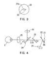
- the glass plate 23 has approximately the same thickness and refractive index as the dichroic mirror 24. Further, as shown in Fig.
- the dichroic mirror 24 is arranged to have an angle of inclination of ⁇ with respect to the optical axis L1
- the glass plate 23 is arranged to have an angle of inclination of 180° minus ⁇ with respect to the optical axis L1.
- the dichroic mirror 24 and the glass plate 23 are flipped up synchronously by an inserting/removing mechanism 66 to be removed from the optical path.
- a known mechanism such as a solenoid and cam (or motor and the like) may be used for the inserting/removing mechanism 66.
- Infrared target light emitted from an infrared light source 41 for focus target projection such as an infrared light-emitting diode passes through a slit target plate 42 and two deflection-angle prisms 43 attached to the target plate 42, is reflected by the half mirror 44, and further passes through the relay lens 21 to the objective lens 25 to be projected onto the fundus Ef (i.e., a focus target is projected thereon).
- the light source 41 and the target plate 42 are moved in synchronization with the focusing lens 32 in the optical axis direction by the moving mechanism 39.
- the light source 41 emits infrared light having a center wavelength of approximately 880nm.
- the alignment target projection optical system 50 includes a pair of first projection optical systems having optical axes arranged laterally symmetrical with respect to the optical axis L1, and a pair of second projection optical systems having optical axes arranged laterally symmetrical with respect to the optical axis L1 forming an angle smaller than the optical axes of the first projection optical systems.
- a pair of the first projection optical systems include infrared light sources 51 such as infrared light-emitting diodes which emit infrared light having a center wavelength of approximately 940nm and collimating lenses 52, respectively, and project infrared target light at an infinite distance onto the eye E with approximately parallel light (i.e., alignment targets are projected thereon).
- a pair of the second projection optical systems include infrared light sources 53 such as infrared light-emitting diodes which emit infrared light having a center wavelength of approximately 940nm, and projects infrared target light at a finite distance onto the eye E with divergent light (i.e., alignment targets are projected thereon).
- infrared light sources 53 such as infrared light-emitting diodes which emit infrared light having a center wavelength of approximately 940nm, and projects infrared target light at a finite distance onto the eye E with divergent light (i.e., alignment targets are projected thereon).
- the optical systems in Fig. 2 are viewed from the side.
- the alignment target projection optical system 50 is presented as if it is arranged vertically; however, it is actually arranged laterally.
- two infrared light sources 55 which project infrared target light having a center wavelength of approximately 880nm for forming working dots are arranged laterally symmetrical with respect to the optical axis L1.
- the light sources 55 may also be configured by arranging an end face of an optical fiber in the vicinity of the apertured mirror 22 and directing infrared light to the optical fiber.
- the light sources 55 are arranged so that, when a working distance between the eye E and the objective lens 25 becomes appropriate, a conjugate position is at a distance equivalent to a half of a corneal radius of curvature of the eye E.
- Infrared illumination light emitted from the infrared illumination light source 58 for anterior-segment observation such as an infrared light-emitting diode is reflected by an anterior-segment of the eye E and the dichroic mirror 24, passes through a field lens 61, a reflection mirror 62, a diaphragm 63 and a relay lens 64, and is photo-received on a CCD camera 65 for anterior-segment observation having sensitivity to the infrared wavelength range to form an image of the anterior-segment of the eye E.
- the light source 58 emits infrared light having a center wavelength of approximately 940nm.
- the CCD camera 65 doubles as image-pickup means for alignment target detection (i.e., the anterior-segment observation optical system 60 doubles as an alignment target detection optical system), and picks up the image of the anterior-segment of the eye E formed by the light source 58 and images of the alignment targets formed by the alignment target projection optical system 50.
- alignment target detection means doubling as anterior-segment image pick-up means as the present embodiment, a dedicated one may be arranged.
- Red fixation target light emitted from a fixation target light source (a fixation lamp) 74 such as a red light-emitting diode passes through an aperture in a shielding plate 71 of a rotary disk 72 and a relay lens 75 to be transmitted through the dichroic mirror 37.
- a part of the red fixation target light transmitted through the dichroic mirror 37 is reflected by the dichroic mirror 34, and passes through the image forming lens 33 to the objective lens 25 to be projected onto the fundus Ef (i.e., a fixation target is projected thereon).
- the disk 72 is provided with eight shielding plates 71, and the aperture in each shielding plate 71 is either for guiding a visual line so that the vicinity of a posterior pole of the fundus of a right eye comes to a center of photographing, for guiding the visual line so that the vicinity of a posterior pole of the fundus of a left eye comes to the center of photographing, or for guiding the visual line so that a periphery of the fundus is photographed.
- the disk 72 is rotated by a pulse motor 73, and one of the eight shielding plates 71 is selectively arranged in front of the light source 74.
- the number of shielding plates 71 is not limited to eight.
- the dichroic mirror 24 and the glass plate 23 are inserted into the optical path of the fundus observation/photographing optical system 30 (i.e., the optical path between the objective lens 25 and the apertured mirror 22) .
- the image of the anterior-segment formed by the light source 58 and the images of the alignment targets formed by the alignment target projection optical system 50 are reflected by the dichroic mirror 24 and picked up by the CCD camera 65.
- Figs. 5A and 5B show the anterior-segment image and the alignment target images picked up by the CCD camera 65 and displayed on the monitor 8.
- Target images Ma and Mb are the alignment target images at an infinite distance formed by the first projection optical systems
- target images Mc and Md are the alignment target images at a finite distance formed by the second projection optical systems.
- the second projection optical systems are arranged so that the target images Mc and Md are formed below the target images Ma and Mb.
- the dichroic mirror 24 and the glass plate 23 are inserted into the optical path of the fundus observation/photographing optical system 30.
- the image of the fundus Ef formed by the illumination optical system for fundus observation and the image of the focus target formed by the focus target projection optical system 40 are transmitted through the dichroic mirror 24 and the glass plate 23 to be picked up by the CCD camera 38.
- the optical axis L1 is deviated (shifted) to be an optical axis L1a by insertion of the dichroic mirror 24, and it is made back to the optical axis L1 by insertion of the glass plate 23. Therefore, the image of the anterior-segment and the image of the fundus Ef are favorably picked up by the CCD camera 65 and the CCD camera 38, respectively, at a time.
- the deviated optical axis L1a does not pass through a center of the photographing diaphragm 31.
- a center of the infrared illumination light for fundus observation in a ring shape reflected from the anterior-segment deviates from the center of the photographing diaphragm 31, and the infrared light reflected from the anterior-segment comes to enter the CCD camera 38 for fundus observation even in a state where the alignment is completed.
- a flare tends to appear in the image of the fundus Ef (observation image). Further, the image of the focus target cannot be accurately detected.
- the dichroic mirror 24 and the glass plate 23 are removed from the optical path by the inserting/removing mechanism 66.
- the image of the fundus Ef is picked up by the CCD camera 35 via the objective lens 25 to the dichroic mirror 34.
- the CCD camera 35 for photographing doubles as the camera for fundus observation.
- Respective image signals outputted from the CCD cameras 65, 38 and 35 are inputted to an image processing part 80.
- the image processing part 80 detects the images of the alignment targets based on the image signal from the CCD camera 65 and the image of the focus target based on the image signal from the CCD camera 38. Further, the image processing part 80 is connected to the monitor 8 to control images displayed thereon.
- the control part 81 is connected with the image processing part 80, the Y-moving part 6, the X-and Z-moving part 7, the joystick 4, the moving mechanism 39, the inserting/removing mechanism 66, the pulse motor 73, a photographing switch 83, a switch part 84 having various switches, the respective light sources, and the like. (In Fig. 2, a part of connection lines are not illustrated.)
- the face of the examinee is supported by the face support part 5.
- the dichroic mirror 24 and the glass plate 23 are inserted into the optical path of the fundus observation/photographing optical system 30, and the image of the anterior-segment picked up by the CCD camera 65 is displayed on the monitor 8.
- the examiner moves the photographing part 3 in the X- and Y-directions so that the image of the anterior-segment is placed in the center of a screen on the monitor 8.
- the examiner moves the photographing part 3 in the Z-direction to bring the image of the anterior-segment into focus.
- Fig. 5A When the image of the anterior-segment comes to place in the center of the screen on the monitor 8, as shown in Fig. 5A, the four target images Ma, Mb, Mc and Md come to be displayed (reflected).
- reference letters Na, Nb, Nc and Nd indicate reticle marks respectively in a line shape
- a reference letter Ne indicates a ring mark for indicating a pupil diameter necessary for the photographing, all of which are electrically formed by the image processing part 80.
- the alignment is made by moving the photographing part 3 in the X- and Y-directions so that the target images Ma, Mb, Mc and Md are respectively placed on the reticle marks Na, Nb, Nc and Nd. Further, the photographing part 3 is moved in the Z-direction to bring the target images Ma to Md into focus.
- the control part 81 obtains information on an alignment state in the X-, Y- and Z-directions based on the target images Ma to Md. That is to say, the control part 81 obtains, as shown in Fig. 6, a deviation (shift) amount ⁇ d with reference to an alignment reference position O in the X- and Y-directions while defining the midpoint between the target images Ma and Mb as a corneal vertex position Mo.
- the control part 81 judges appropriateness of the alignment state in the X- and Y-directions (i.e., alignment completion) based on whether the deviation amount ⁇ d stably falls within a predetermined first allowable range A of alignment completion for a predetermined time (for example, 10 frames of image processing, 0.3 second, or the like) (i.e., a first reference condition for alignment is satisfied). Further, the alignment state in the Z-direction is detected through a comparison of a distance between the target images Ma and Mb to a distance between the target images Mc and Md.
- the control part 81 obtains a deviation (shift) amount with respect to an alignment reference position in the Z-direction, and judges appropriateness of the alignment state in the Z-direction (i.e., alignment completion) based on whether the deviation amount stably falls within a predetermined first allowable range of alignment completion for a predetermined time (i.e., a first reference condition for alignment is satisfied).
- the display switching is made from the image of the anterior-segment to the image of the fundus Ef.
- a mark 100 for informing the alignment completion blinks on the monitor 8.
- the examiner may be informed that the alignment is proper.
- the examiner presses a switch 84c in the switch part 84 to make the display switching from the image of the anterior-segment to the image of the fundus Ef.
- the switch 84c is pressed, the image of the fundus Ef picked up by the CCD camera 38 is displayed on the monitor 8.
- the control part 81 controls to make the display switching from the image of the anterior-segment to the image of the fundus Ef in accordance with the judgment of the alignment completion in the X-, Y-, and Z-directions.
- Fig. 7 is an example of the screen showing the image of the anterior-segment when the alignment with the right eye is completed.
- the appropriateness of the direction of the visual line is judged based on whether a pupil center P1 detected from the image of the anterior-segment is stably positioned within an area T1 for judgment of the direction of the visual line for a predetermined time.
- the fixation target which guides the vicinity of the posterior pole of the fundus of the right eye to the center of photographing is previously presented.
- the direction of the visual line is judged to be proper.
- the visual line does not settle and goes out of the area T1.
- the appropriateness of the pupil diameter is judged based on whether a pupil edge P2 detected from the image of the anterior-segment is larger than an area T2 for judgment of the pupil diameter or not.
- Size of the area T2 is set with reference to the center of the display on the monitor 8 (an image-pickup optical axis) in such a diameter as to allow the passage of the infrared illumination light for fundus observation and the visible illumination light for photographing (e.g., 4mm in diameter). If the pupil edge P2 is larger than the area T2, illumination light intensity at the time of photographing is adequately secured, and also the focus target is projected onto the fundus Ef.
- the display switching is automatically made from the image of the anterior-segment to the image of the fundus Ef.
- the mark 100 blinks.
- information as such is displayed on the monitor 8 to inform the examiner thereof.
- the examiner may previously take necessary measures before the photographing, such as giving notice to the examinee to fixate on the fixation target, having a break so that the pupil diameter becomes larger, or the like.
- Fig. 8 is an example of the screen when the display switching to the image of the fundus Ef is made.
- two working dots W formed by the light sources 55 come to be displayed.
- the examiner confirms the focus of the working dots w, a flare in the image of the fundus Ef, and the like while observing the image of the fundus Ef, and further performs alignment through operation of the joystick 4 so that the photographing may be performed in a desired state.
- the working dots W displayed along with the image of the fundus Ef come not to be displayed. Once the working dots W come not to be displayed, the alignment while observing the image of the fundus Ef becomes difficult to perform.
- the control part 81 obtains information on the alignment state in the X-, Y-, and Z-directions based on the image signal from the CCD camera 65 for the anterior-segment observation.
- the second allowable range B is, for example, a range of ⁇ 3-4mm with respect to the alignment reference position O. If the deviation amount ⁇ d exceeds the second allowable range B, the infrared illumination light becomes difficult to reach the fundus Ef, so that the image of the fundus Ef tends to be unobservable. Similarly, for the Z-direction, observation is made to know whether or not the deviation amount falls within a predetermined second allowable range of alignment which is set greater than the first allowable range for alignment completion (i.e., whether or not a second reference condition for alignment is satisfied).
- the second allowable range in the Z-direction is set, for example, as a distance out of which the working dots W become unobservable.
- the display switching is automatically made from the image of the fundus Ef to the image of the anterior-segment.
- a mark informing the switching to the image of the anterior-segment is displayed on the monitor 8 so that the examiner may press the switch 84c to switch from the image of the fundus Ef to the image of the anterior-segment.
- the focus target images S1 and S2 formed by the focus target projection optical system 40 are displayed in the center. Therefore, the light source 41, the target plate 42 and the focusing lens 32 are moved in the optical axis direction based on the target images S1 and S2 for focusing on the fundus Ef. If the fundus Ef is not brought into focus, the target images S1 and S2 are displayed separately, and if the fundus Ef is brought into focus, they are displayed in coincident with each other. While the focusing can be performed manually, the present apparatus is provided with an automatic focusing mechanism.
- the target images S1 and S2 are detected and processed by the image processing part 80, and their separation information is transferred to the control part 81. Based on the separation information on the target images S1 and S2, the control part 81 drives and controls the movement mechanism 39 so that both the images coincide with each other to perform focusing on the fundus Ef. Upon completion of the focusing, the examiner presses the photographing switch 83 to perform photographing.
- the control part 81 drives and controls the inserting/removing mechanism 66 to remove the dichroic mirror 24 and the glass plate 23 from the optical path, and have the light source 14 emit light.
- the fundus Ef is illuminated with the visible light, and the light reflected from the fundus Ef is photo-received on the CCD camera 35 to form the image of the fundus Ef.
- the image of the fundus Ef picked up by the CCD camera 35 is displayed in colors.
- the image of the fundus Ef (a photographed image) is stored in an image memory included in the image processing part 80.
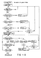
- the examiner performs rough alignment of the photographing part 3 with the eye E through operation of the joystick 4 while observing the image of the anterior-segment displayed on the monitor 8.
- the control part 81 controls to obtain the information on the alignment state in the X-, Y-, and Z-directions based on the target images Ma to Md, and drives and controls the X- and Z-moving part 7 and the Y-moving part 6 to perform automatic alignment so as to satisfy the first reference condition. Then, when the alignment is completed, the control part 81 stops the automatic alignment.
- control part 81 controls to make the display switching from the image of the anterior-segment to the image of the fundus Ef, based on the setting of whether the display switching is made automatically or manually, and based on the judgment of the appropriateness of the direction of the visual line and the pupil diameter.
- the display switching is made from the image of the fundus Ef to the image of the anterior-segment based on the setting of the display switching.
- the control part 81 makes judgment based on whether or not the deviation amount ⁇ d in the X- and Y-directions falls within a predetermined third allowable range C of alignment which is set greater than the first allowable range A (the third allowable range C is preferably smaller than the second allowable range B) (i.e., whether or not a third reference condition for alignment is satisfied). Same shall apply to the deviation amount ⁇ d in the Z-direction.
- the control part 81 stops the automatic alignment until the deviation amount ⁇ d exceeds the third allowable range, and re-implements the automatic alignment when the deviation amount ⁇ d exceeds the third allowable range.
- the third allowable range C in the X- and Y-directions is, for example, a range of ⁇ 1.5mm with respect to the alignment reference position O.
- the examiner may perform fine adjustment of the photographing position through operation of the joystick 4 while observing the image of the fundus Ef displayed on the monitor 8.
- the display switching is made from the image of the anterior-segment to the image of the fundus Ef, as shown in Fig. 8, the two working dots W formed by the light sources 55 are displayed.
- the examiner confirms the focus of the working dots W, the flare on the image of the fundus Ef and the like and further performs alignment through operation of the joystick 4 while observing the image of the fundus Ef so that the photographing may be performed in a desired state.
- the automatic alignment utilizing the image of the anterior-segment, there is a case where a flare slightly appears on the image of the fundus Ef due to individuality in a cornea and a crystalline lens; however, as the manual alignment may be performed in order to avoid the flare, unfavorable photographing may be prevented. Further, when the alignment state comes not to satisfy the third reference condition, the automatic alignment is performed while displaying the image of the fundus Ef (observation image), so that a burden of the manual alignment is reduced and the alignment may be performed easily.
- the photographing switch 83 is pressed to implement the photographing.
- such a constitution may also be employed that, when switched to a state of anterior-segment observation, the image of the anterior-segment is largely displayed and the image of the fundus is displayed on a small screen synthetically, and when switched to a state of fundus observation, the image of the fundus Ef is largely displayed and the image of the anterior-segment is displayed on the small screen synthetically.
Applications Claiming Priority (2)
| Application Number | Priority Date | Filing Date | Title |
|---|---|---|---|
| JP2003400196A JP4268861B2 (ja) | 2003-11-28 | 2003-11-28 | 眼底カメラ |
| JP2003400196 | 2003-11-28 |
Publications (2)
| Publication Number | Publication Date |
|---|---|
| EP1535566A1 true EP1535566A1 (de) | 2005-06-01 |
| EP1535566B1 EP1535566B1 (de) | 2016-09-21 |
Family
ID=34463899
Family Applications (1)
| Application Number | Title | Priority Date | Filing Date |
|---|---|---|---|
| EP04028136.2A Expired - Fee Related EP1535566B1 (de) | 2003-11-28 | 2004-11-26 | Funduskamera |
Country Status (3)
| Country | Link |
|---|---|
| US (1) | US7331670B2 (de) |
| EP (1) | EP1535566B1 (de) |
| JP (1) | JP4268861B2 (de) |
Cited By (4)
| Publication number | Priority date | Publication date | Assignee | Title |
|---|---|---|---|---|
| EP1972266A1 (de) * | 2007-03-01 | 2008-09-24 | Nidek Co., Ltd. | Funduskamera |
| EP1974656A3 (de) * | 2007-03-01 | 2009-03-04 | Nidek Co., Ltd | Funduskamera |
| EP2057938A1 (de) * | 2007-11-08 | 2009-05-13 | Nidek Co., Ltd. | Funduskamera |
| EP2394569A1 (de) * | 2010-06-10 | 2011-12-14 | Nidek Co., Ltd | Ophthalmische Vorrichtung |
Families Citing this family (12)
| Publication number | Priority date | Publication date | Assignee | Title |
|---|---|---|---|---|
| US7445336B2 (en) * | 2004-10-21 | 2008-11-04 | Nidek Co., Ltd. | Fundus camera |
| JP4628763B2 (ja) | 2004-12-01 | 2011-02-09 | 株式会社ニデック | 眼底カメラ |
| JP4886389B2 (ja) * | 2006-06-29 | 2012-02-29 | 株式会社ニデック | 眼底カメラ |
| US7553020B2 (en) * | 2006-09-29 | 2009-06-30 | Welch Allyn, Inc. | Medical diagnostic instrument with variable focus liquid lens |
| JP4987426B2 (ja) * | 2006-11-02 | 2012-07-25 | 株式会社ニデック | 眼科測定装置 |
| JP2008295971A (ja) | 2007-06-04 | 2008-12-11 | Nidek Co Ltd | 眼底カメラ |
| JP5317049B2 (ja) * | 2008-08-04 | 2013-10-16 | 株式会社ニデック | 眼底カメラ |
| JP2010035727A (ja) * | 2008-08-04 | 2010-02-18 | Nidek Co Ltd | 眼底カメラ |
| US8888765B1 (en) | 2008-10-10 | 2014-11-18 | Kameran Lashkari | System and method for use of infrared binocular indirect ophthalmoscopes in imaging and photodynamic therapy |
| TWI450705B (zh) * | 2011-10-28 | 2014-09-01 | Crystalvue Medical Corp | Three - axis positioning device and method for ophthalmic detection instrument |
| WO2017025583A1 (en) | 2015-08-12 | 2017-02-16 | Carl Zeiss Meditec, Inc. | Alignment improvements for ophthalmic diagnostic systems |
| CN109758115B (zh) * | 2019-02-26 | 2024-04-12 | 上海鹰瞳医疗科技有限公司 | 引导组件和眼底相机 |
Citations (9)
| Publication number | Priority date | Publication date | Assignee | Title |
|---|---|---|---|---|
| JPH0646999A (ja) | 1992-07-31 | 1994-02-22 | Nidek Co Ltd | アライメント検出装置 |
| US5463430A (en) | 1992-07-31 | 1995-10-31 | Nidek Co., Ltd. | Examination apparatus for examining an object having a spheroidal reflective surface |
| JP2000005131A (ja) * | 1998-06-24 | 2000-01-11 | Canon Inc | 眼底カメラ |
| US6022108A (en) * | 1996-06-28 | 2000-02-08 | Nidek Co., Ltd. | Opthalmic apparatus for judging alignment conditions based on target images |
| EP1138256A2 (de) * | 2000-03-22 | 2001-10-04 | Nidek Co., Ltd. | Funduskamera mit sichtbarer und unsichtbarer Beleuchtung |
| US20010028440A1 (en) * | 2000-03-17 | 2001-10-11 | Tomoyuki Iwanaga | Ophthalmologic apparatus |
| JP2003088503A (ja) * | 2001-09-20 | 2003-03-25 | Canon Inc | 眼底カメラ |
| WO2003049607A1 (en) * | 2001-12-13 | 2003-06-19 | Vision Instruments Pty Ltd | System to facilitate alignment and focussing of a fundus camera |
| EP1452128A1 (de) * | 2003-02-28 | 2004-09-01 | Nidek Co., Ltd. | Funduskamera |
Family Cites Families (7)
| Publication number | Priority date | Publication date | Assignee | Title |
|---|---|---|---|---|
| JP3569026B2 (ja) | 1995-04-05 | 2004-09-22 | 株式会社コーナン・メディカル | 眼底カメラ |
| JP3868641B2 (ja) * | 1998-11-20 | 2007-01-17 | 富士通株式会社 | 紙葉繰出機構 |
| JP2000287936A (ja) | 1999-04-06 | 2000-10-17 | Canon Inc | 眼科撮影装置 |
| JP2001346764A (ja) | 2000-06-08 | 2001-12-18 | Topcon Corp | 眼底カメラ |
| JP2003245253A (ja) | 2002-02-26 | 2003-09-02 | Canon Inc | 眼底カメラ |
| JP2004024470A (ja) * | 2002-06-25 | 2004-01-29 | Canon Inc | 眼科撮影装置 |
| US7445336B2 (en) * | 2004-10-21 | 2008-11-04 | Nidek Co., Ltd. | Fundus camera |
-
2003
- 2003-11-28 JP JP2003400196A patent/JP4268861B2/ja not_active Expired - Fee Related
-
2004
- 2004-11-26 US US10/996,473 patent/US7331670B2/en not_active Expired - Fee Related
- 2004-11-26 EP EP04028136.2A patent/EP1535566B1/de not_active Expired - Fee Related
Patent Citations (9)
| Publication number | Priority date | Publication date | Assignee | Title |
|---|---|---|---|---|
| JPH0646999A (ja) | 1992-07-31 | 1994-02-22 | Nidek Co Ltd | アライメント検出装置 |
| US5463430A (en) | 1992-07-31 | 1995-10-31 | Nidek Co., Ltd. | Examination apparatus for examining an object having a spheroidal reflective surface |
| US6022108A (en) * | 1996-06-28 | 2000-02-08 | Nidek Co., Ltd. | Opthalmic apparatus for judging alignment conditions based on target images |
| JP2000005131A (ja) * | 1998-06-24 | 2000-01-11 | Canon Inc | 眼底カメラ |
| US20010028440A1 (en) * | 2000-03-17 | 2001-10-11 | Tomoyuki Iwanaga | Ophthalmologic apparatus |
| EP1138256A2 (de) * | 2000-03-22 | 2001-10-04 | Nidek Co., Ltd. | Funduskamera mit sichtbarer und unsichtbarer Beleuchtung |
| JP2003088503A (ja) * | 2001-09-20 | 2003-03-25 | Canon Inc | 眼底カメラ |
| WO2003049607A1 (en) * | 2001-12-13 | 2003-06-19 | Vision Instruments Pty Ltd | System to facilitate alignment and focussing of a fundus camera |
| EP1452128A1 (de) * | 2003-02-28 | 2004-09-01 | Nidek Co., Ltd. | Funduskamera |
Non-Patent Citations (2)
| Title |
|---|
| PATENT ABSTRACTS OF JAPAN vol. 2000, no. 04 31 August 2000 (2000-08-31) * |
| PATENT ABSTRACTS OF JAPAN vol. 2003, no. 07 3 July 2003 (2003-07-03) * |
Cited By (8)
| Publication number | Priority date | Publication date | Assignee | Title |
|---|---|---|---|---|
| EP1972266A1 (de) * | 2007-03-01 | 2008-09-24 | Nidek Co., Ltd. | Funduskamera |
| EP1974656A3 (de) * | 2007-03-01 | 2009-03-04 | Nidek Co., Ltd | Funduskamera |
| US7641340B2 (en) | 2007-03-01 | 2010-01-05 | Nidek Co., Ltd. | Fundus camera |
| US7651223B2 (en) | 2007-03-01 | 2010-01-26 | Nidek Co., Ltd. | Fundus camera |
| EP2057938A1 (de) * | 2007-11-08 | 2009-05-13 | Nidek Co., Ltd. | Funduskamera |
| US7878653B2 (en) | 2007-11-08 | 2011-02-01 | Nidek Co., Ltd. | Fundus camera |
| EP2394569A1 (de) * | 2010-06-10 | 2011-12-14 | Nidek Co., Ltd | Ophthalmische Vorrichtung |
| US8857987B2 (en) | 2010-06-10 | 2014-10-14 | Nidek Co., Ltd. | Ophthalmic apparatus |
Also Published As
| Publication number | Publication date |
|---|---|
| EP1535566B1 (de) | 2016-09-21 |
| JP4268861B2 (ja) | 2009-05-27 |
| JP2005160550A (ja) | 2005-06-23 |
| US20050117115A1 (en) | 2005-06-02 |
| US7331670B2 (en) | 2008-02-19 |
Similar Documents
| Publication | Publication Date | Title |
|---|---|---|
| US7445336B2 (en) | Fundus camera | |
| US7364295B2 (en) | Fundus camera | |
| US7219996B2 (en) | Fundus camera | |
| US7837329B2 (en) | Fundus camera | |
| EP1452128B1 (de) | Funduskamera | |
| US7354153B2 (en) | Fundus camera | |
| EP1535566B1 (de) | Funduskamera | |
| JP4359489B2 (ja) | 眼底カメラ | |
| US8646912B2 (en) | Fundus photographing apparatus | |
| US7641340B2 (en) | Fundus camera | |
| JP5554610B2 (ja) | 眼底撮影装置 | |
| JP4886388B2 (ja) | 眼底カメラ | |
| JP5545982B2 (ja) | 眼底カメラ | |
| JP4886389B2 (ja) | 眼底カメラ | |
| JP5328517B2 (ja) | 眼底撮影装置 | |
| JP2006116090A (ja) | 眼底カメラ | |
| JP4481727B2 (ja) | 眼底カメラ | |
| JP5522629B2 (ja) | 眼底撮影装置 | |
| JP5807701B2 (ja) | 眼底撮影装置 | |
| JP4492854B2 (ja) | 眼底カメラ | |
| JP6292331B2 (ja) | 眼底撮影装置 | |
| JP6107906B2 (ja) | 眼底撮影装置 |
Legal Events
| Date | Code | Title | Description |
|---|---|---|---|
| PUAI | Public reference made under article 153(3) epc to a published international application that has entered the european phase |
Free format text: ORIGINAL CODE: 0009012 |
|
| AK | Designated contracting states |
Kind code of ref document: A1 Designated state(s): AT BE BG CH CY CZ DE DK EE ES FI FR GB GR HU IE IS IT LI LU MC NL PL PT RO SE SI SK TR |
|
| AX | Request for extension of the european patent |
Extension state: AL HR LT LV MK YU |
|
| 17P | Request for examination filed |
Effective date: 20051026 |
|
| AKX | Designation fees paid |
Designated state(s): DE FR GB |
|
| 17Q | First examination report despatched |
Effective date: 20071017 |
|
| GRAP | Despatch of communication of intention to grant a patent |
Free format text: ORIGINAL CODE: EPIDOSNIGR1 |
|
| INTG | Intention to grant announced |
Effective date: 20160224 |
|
| GRAS | Grant fee paid |
Free format text: ORIGINAL CODE: EPIDOSNIGR3 |
|
| GRAA | (expected) grant |
Free format text: ORIGINAL CODE: 0009210 |
|
| RAP1 | Party data changed (applicant data changed or rights of an application transferred) |
Owner name: NIDEK CO., LTD. |
|
| AK | Designated contracting states |
Kind code of ref document: B1 Designated state(s): DE FR GB |
|
| REG | Reference to a national code |
Ref country code: GB Ref legal event code: FG4D |
|
| REG | Reference to a national code |
Ref country code: DE Ref legal event code: R096 Ref document number: 602004049966 Country of ref document: DE |
|
| REG | Reference to a national code |
Ref country code: FR Ref legal event code: PLFP Year of fee payment: 13 |
|
| PGFP | Annual fee paid to national office [announced via postgrant information from national office to epo] |
Ref country code: DE Payment date: 20161123 Year of fee payment: 13 Ref country code: GB Payment date: 20161123 Year of fee payment: 13 Ref country code: FR Payment date: 20161111 Year of fee payment: 13 |
|
| REG | Reference to a national code |
Ref country code: DE Ref legal event code: R097 Ref document number: 602004049966 Country of ref document: DE |
|
| PLBE | No opposition filed within time limit |
Free format text: ORIGINAL CODE: 0009261 |
|
| STAA | Information on the status of an ep patent application or granted ep patent |
Free format text: STATUS: NO OPPOSITION FILED WITHIN TIME LIMIT |
|
| 26N | No opposition filed |
Effective date: 20170622 |
|
| REG | Reference to a national code |
Ref country code: DE Ref legal event code: R119 Ref document number: 602004049966 Country of ref document: DE |
|
| GBPC | Gb: european patent ceased through non-payment of renewal fee |
Effective date: 20171126 |
|
| REG | Reference to a national code |
Ref country code: FR Ref legal event code: ST Effective date: 20180731 |
|
| PG25 | Lapsed in a contracting state [announced via postgrant information from national office to epo] |
Ref country code: DE Free format text: LAPSE BECAUSE OF NON-PAYMENT OF DUE FEES Effective date: 20180602 Ref country code: FR Free format text: LAPSE BECAUSE OF NON-PAYMENT OF DUE FEES Effective date: 20171130 |
|
| PG25 | Lapsed in a contracting state [announced via postgrant information from national office to epo] |
Ref country code: GB Free format text: LAPSE BECAUSE OF NON-PAYMENT OF DUE FEES Effective date: 20171126 |