EP1533891B1 - Vorrichtung zur Positionserfassung der magnetischen Pole - Google Patents
Vorrichtung zur Positionserfassung der magnetischen Pole Download PDFInfo
- Publication number
- EP1533891B1 EP1533891B1 EP04026932A EP04026932A EP1533891B1 EP 1533891 B1 EP1533891 B1 EP 1533891B1 EP 04026932 A EP04026932 A EP 04026932A EP 04026932 A EP04026932 A EP 04026932A EP 1533891 B1 EP1533891 B1 EP 1533891B1
- Authority
- EP
- European Patent Office
- Prior art keywords
- magnetic pole
- magnetic
- pole
- rotor
- inferring
- Prior art date
- Legal status (The legal status is an assumption and is not a legal conclusion. Google has not performed a legal analysis and makes no representation as to the accuracy of the status listed.)
- Ceased
Links
- 230000005284 excitation Effects 0.000 claims description 89
- 230000001360 synchronised effect Effects 0.000 claims description 17
- 238000000034 method Methods 0.000 description 60
- 230000004907 flux Effects 0.000 description 23
- 230000008569 process Effects 0.000 description 13
- 239000013598 vector Substances 0.000 description 12
- 230000008859 change Effects 0.000 description 6
- 238000004804 winding Methods 0.000 description 6
- 238000001514 detection method Methods 0.000 description 5
- 238000004364 calculation method Methods 0.000 description 3
- 238000010586 diagram Methods 0.000 description 3
- 238000013459 approach Methods 0.000 description 2
- 238000001914 filtration Methods 0.000 description 2
- 230000004044 response Effects 0.000 description 2
- 230000001052 transient effect Effects 0.000 description 2
- 230000007423 decrease Effects 0.000 description 1
- 230000001419 dependent effect Effects 0.000 description 1
- 230000003292 diminished effect Effects 0.000 description 1
- 230000006870 function Effects 0.000 description 1
Images


Classifications
-
- H—ELECTRICITY
- H02—GENERATION; CONVERSION OR DISTRIBUTION OF ELECTRIC POWER
- H02P—CONTROL OR REGULATION OF ELECTRIC MOTORS, ELECTRIC GENERATORS OR DYNAMO-ELECTRIC CONVERTERS; CONTROLLING TRANSFORMERS, REACTORS OR CHOKE COILS
- H02P6/00—Arrangements for controlling synchronous motors or other dynamo-electric motors using electronic commutation dependent on the rotor position; Electronic commutators therefor
- H02P6/20—Arrangements for starting
-
- H—ELECTRICITY
- H02—GENERATION; CONVERSION OR DISTRIBUTION OF ELECTRIC POWER
- H02P—CONTROL OR REGULATION OF ELECTRIC MOTORS, ELECTRIC GENERATORS OR DYNAMO-ELECTRIC CONVERTERS; CONTROLLING TRANSFORMERS, REACTORS OR CHOKE COILS
- H02P1/00—Arrangements for starting electric motors or dynamo-electric converters
- H02P1/16—Arrangements for starting electric motors or dynamo-electric converters for starting dynamo-electric motors or dynamo-electric converters
- H02P1/46—Arrangements for starting electric motors or dynamo-electric converters for starting dynamo-electric motors or dynamo-electric converters for starting an individual synchronous motor
-
- H—ELECTRICITY
- H02—GENERATION; CONVERSION OR DISTRIBUTION OF ELECTRIC POWER
- H02P—CONTROL OR REGULATION OF ELECTRIC MOTORS, ELECTRIC GENERATORS OR DYNAMO-ELECTRIC CONVERTERS; CONTROLLING TRANSFORMERS, REACTORS OR CHOKE COILS
- H02P21/00—Arrangements or methods for the control of electric machines by vector control, e.g. by control of field orientation
- H02P21/14—Estimation or adaptation of machine parameters, e.g. flux, current or voltage
- H02P21/18—Estimation of position or speed
-
- H—ELECTRICITY
- H02—GENERATION; CONVERSION OR DISTRIBUTION OF ELECTRIC POWER
- H02P—CONTROL OR REGULATION OF ELECTRIC MOTORS, ELECTRIC GENERATORS OR DYNAMO-ELECTRIC CONVERTERS; CONTROLLING TRANSFORMERS, REACTORS OR CHOKE COILS
- H02P6/00—Arrangements for controlling synchronous motors or other dynamo-electric motors using electronic commutation dependent on the rotor position; Electronic commutators therefor
- H02P6/14—Electronic commutators
- H02P6/16—Circuit arrangements for detecting position
- H02P6/18—Circuit arrangements for detecting position without separate position detecting elements
- H02P6/183—Circuit arrangements for detecting position without separate position detecting elements using an injected high frequency signal
-
- H—ELECTRICITY
- H02—GENERATION; CONVERSION OR DISTRIBUTION OF ELECTRIC POWER
- H02P—CONTROL OR REGULATION OF ELECTRIC MOTORS, ELECTRIC GENERATORS OR DYNAMO-ELECTRIC CONVERTERS; CONTROLLING TRANSFORMERS, REACTORS OR CHOKE COILS
- H02P2203/00—Indexing scheme relating to controlling arrangements characterised by the means for detecting the position of the rotor
- H02P2203/11—Determination or estimation of the rotor position or other motor parameters based on the analysis of high-frequency signals
-
- H—ELECTRICITY
- H02—GENERATION; CONVERSION OR DISTRIBUTION OF ELECTRIC POWER
- H02P—CONTROL OR REGULATION OF ELECTRIC MOTORS, ELECTRIC GENERATORS OR DYNAMO-ELECTRIC CONVERTERS; CONTROLLING TRANSFORMERS, REACTORS OR CHOKE COILS
- H02P2207/00—Indexing scheme relating to controlling arrangements characterised by the type of motor
- H02P2207/05—Synchronous machines, e.g. with permanent magnets or DC excitation
Definitions
- the present invention relates to detection of a position of a magnetic pole in a rotor included in a synchronous motor.
- a current is caused to flow through each of phase windings according to a position of a magnetic pole in a rotor for the purpose of generating a desired torque.
- An encoder or another sensor is used to detect the position of a magnetic pole in the rotor so that a current will flow in the direction of an appropriate excitation phase.
- This necessitates the employment of a sensor that is sensitive to an absolute value permitting detection of the position of a magnetic pole or the work of aligning a sensor with the position of a magnetic pole.
- detection of the position of a magnetic pole is performed at the time of starting a motor.
- a microscopic voltage transient is produced in a salient-pole type motor, and a position of a magnetic pole is inferred from the microscopic voltage transient and a change rate of a component of a current flowing through the motor.
- a high-frequency voltage is applied to a salient-pole type motor.
- a high-frequency current whose frequency is identical to the frequency of the high-frequency voltage is sampled from a current flowing through an armature.
- the position of a rotor is inferred from the high-frequency current.
- a positive or negative offset is added to the inferred position of a rotor according to the polarity of the high-frequency current detected immediately after the motor is started, whereby an initial value of the inferred position of a rotor is calculated.
- a high-frequency voltage is applied to a salient-pole type motor, and a position of a magnetic pole is detected based on a detected high-frequency current.
- a short-period current is caused.to flow in the direction of a predetermined excitation phase in a stator. Based on the direction of a motion made by a rotor at that time, the excitation phase is changed and the short-period current is caused to flow. This process is repeated in order to detect the position of a magnetic pole.
- a rotor included in a permanent-magnet synchronous motor falls broadly into a surface permanent magnet (SPM) type having a permanent magnet bonded to the surface of a rotor and an interior permanent magnet (IPM) type having a permanent magnet embedded in a rotor.
- SPM surface permanent magnet
- IPM interior permanent magnet
- the SPM motor is of a non-salient pole type in which a d-axis inductance and a q-axis inductance offered by windings on an armature are equal to each other
- the IPM motor is of a salient-pole type in which the d-axis and q-axis inductances are different from each other.
- a method described in the fifth patent document can be adapted to any synchronous motor irrespective of whether the synchronous motor is of the salient-pole type or non-salient pole type.
- the method requires some motion of a rotor. If the rotor makes no motion because of large friction of a machine, a position of a magnetic pole cannot be detected correctly.
- EP 1 085 650 A2 discloses a method for detecting a rotor magnetic pole position of a synchronous motor.
- the arrangement of EP 1 085 650 A2 comprises a synchronous motor including a rotor, a power amplifier for applying command voltages and an encoder for detecting a rotor position of a motor.
- an electric current is supplied to a prescribed excitation phase of the stator of the motor.
- the direction of movement of the rotor is obtained by the application of the electrical current and a rotor magnetic pole position is estimated on the basis of an obtained direction of movement.
- a prescribed excitation phase is specified for supplying a subsequent electrical current based on an estimated magnetic pole position of the rotor.
- EP 1 324 483 A2 discloses a method for determining the position of the rotor of a synchronous alternating-current permanent-magnet machine. This method comprises the steps of applying a voltage command with a high frequency with the excitation phase, measuring the current of the motor and extracting a current that is linked to the applied voltage, obtaining the electrical angle from the applied voltage and the corresponding current, and determining the position of the rotor based on the electrical angle.
- the present applicant has proposed a method of detecting a position of a magnetic pole without the motion of a rotor in Patent Application No. 2003-362379 .
- the method utilizes the electric characteristic of the salient-pole type and magnetic saturation and cannot therefore be adapted to the non-salient pole type SPM motor.
- an object of the present invention is to provide a position-of magnetic-pole detecting device capable of accurately detecting a position of a magnetic pole without the necessity of learning in advance a mechanical characteristic concerning friction or the properties of a motor (whether the motor is of a salient-pole type or non-salient-pole type, with or without magnetic saturation, or other properties.)
- the means for selecting either of the first and second position-of magneticpole inferring means may autonomously select the second position-of-magnetic position inferring means.
- the means for selecting either of the first and second position-of magnetic-pole inferring means may autonomously select the first position-of-magnetic-pole inferring means.
- Fig. 1 is a block diagram of an embodiment of motor control equipment based on which a position-of-magnetic-pole detecting device in accordance with the present invention is realized.
- switches SA and SB For normal driving and control of a motor, switches SA and SB have the contacts a thereof made.
- a converter 6 for converting a three-phase current into a dq-phase current converts a three-phase fed-back current into a dq-phase fed-back current.
- the d-phase and q-phase current components of the dq-phase fed-back current are subtracted from d-phase and q-phase current commands respectively, whereby deviations of the d-phase and q-phase current components are calculated.
- a current controller 1 performs feedback control on a current and issues a voltage command.
- a position-of-magnetic-pole inferring unit 7 calculates an excitation phase ⁇ . Based on the excitation phase, a converter 2 for converting a dq-phase voltage into a three-phase voltage converts the voltage command into a three-phase voltage command. Consequently, a motor 4 is driven or controlled via an amplifier 3. The procedure for driving or controlling the motor 4 does not change from a conventional motor driving/control method.
- the switches SA and SB, a current command generator 8, and a voltage command generator 9 are added to the foregoing motor driving elements 1, 2, 3, 5, and 6, and the configuration of the position-of-magnetic-pole inferring unit 7 is modified.
- a position-of-magnetic-pole detecting device is realized.
- the present embodiment includes, as a position-of-magnetic-pole detecting means, a means for detecting a position of a magnetic pole by actuating a rotor included in a motor (hereinafter, the means shall be referred to as a first position-of-magnetic-pole inferring means, and the method shall be referred to as a first position-of-magnetic-pole inferring method), and a means for detecting a position of a magnetic pole in a motor, which has the electrical characteristic of a salient-pole type, on the basis of a fed-back current, which is returned responsively to application of a voltage to the motor, without actuating the rotor (hereinafter, the means shall be referred to as a second position-of-magnetic-pole inferring means, and the method shall be referred to as a second position-of-magnetic-pole inferring method).
- a position-of-magnetic-pole detecting means a means for detecting a position
- the first position-of-magnetic-pole inferring means included in the present embodiment is based on a means described in the fifth patent document.
- the switch SA has a contact b thereof made and the switch SB has the contact a thereof made.
- the motor is thus disconnected from a normal control system.
- the current command generator 8 transmits a current having a d-phase current component of a zero level and a q-phase current component of a predetermined dc exciting current, whereby the motor is driven.
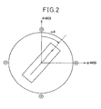
- the torque value is expressed as follows: I ⁇ ⁇ ⁇ sin ⁇
- the direction of rotation produced by the torque is determined with an angle ⁇ formed between the current vector I and magnetic flux vector ⁇ .
- sin ⁇ is larger than 0.
- the rotor is therefore rotated in a positive direction.
- sin ⁇ is smaller than 0.
- the rotor is therefore rotated in a negative direction. Consequently, according to the present embodiment, a direct current is caused to flow in the direction of an excitation phase of 180° in a stator for the purpose of detecting a direction of rotation in which the rotor rotates. If the rotor rotates in the positive direction, a position of a magnetic pole in the rotor (position of the terminal point of the magnetic flux vector ⁇ ) is thought to lie within a domain whose width is determined with a range of excitation phases in the stator from 180° to 360°. If the rotor rotates in the negative direction, the position of a magnetic pole in the rotor is thought to lie within a domain whose width is determined with a range of excitation phases from 0° to 180°.
- a direct current is caused to flow in the direction of an intermediate excitation phase within the range of excitation phases (range from 180° to 360° or range from 0° to 180°) determining the width of the domain in the rotor where the position of a magnetic pole lies.
- the direction of rotation of the rotor is then detected, and the domain in the rotor where the position of a magnetic pole lies is detected. This procedure is repeated in order to sequentially reduce the domain in the rotor where the position of a magnetic pole lies. Finally, the position of a magnetic pole in the rotor is detected.
- a current is first caused to flow in the direction of an excitation phase of 180°.
- the rotor is therefore rotated in the positive direction.
- the position of a magnetic pole in the rotor is thought to lie within a domain whose width is determined with the range of excitation phases from 180° to 360°.
- a direct current is caused to flow in the direction of an excitation phase of 270° which halves the domain.
- the position of a magnetic pole in the rotor is thought to lie within a domain whose width is determined with a range of excitation angles from 270° to 360°.
- a direct current is caused to flow in the direction of an excitation phase of 315° that is the intermediate value within the range from 270° to 360°.
- the angle ⁇ is calculated to be 35, and the direction of rotation is the positive direction.
- a direct current is then caused to flow in the direction of an excitation phase of 337.5° that is the intermediate value within the range from 315° to 360°.
- the angle ⁇ is calculated to be 12.5, and the rotor rotates in the positive direction.
- a direct current is then caused to flow in the direction of the excitation phase of 351.5627°, and the direction of rotation is detected.
- a domain in the rotor where the position of a magnetic pole is thought to lie is reduced sequentially.
- the checking of a domain where the position of a magnetic pole is thought to lie is repeated until the rotor does not rotate any longer or for a predetermined number of times, whereby the position of a magnetic pole in the rotor is determined.
- the second position-of-magnetic-pole inferring means included in the present embodiment is based on the method and means proposed in the Japanese Patent Application No. 2003-362379 .
- the switch SB has the contact b thereof made, and the voltage command generator transmits a voltage command whose d-phase component is a high-frequency voltage or a rectangular-wave voltage.
- a position of a magnetic pole is detected without any motion of the rotor. The principles of the method will be described below.
- a magnetic flux ( ⁇ d , ⁇ q ) is defined in a dq coordinate system associated with a salient-pole type motor including two phase windings
- the deviation of a rotor (magnetic pole) from a d-axis is, as shown in Fig.
- L 0 denotes an average inductance independent of an excitation phase
- L 2 denotes a variation inductance dependent on the excitation phase.
- L d L d +L 2
- V dq (a synthetic voltage having a d-axis voltage component and a q-axis voltage component) is provided by the following formula (2):
- V dq Rs ⁇ i dq + d / dt ⁇ dq + ⁇ dq
- Rs denotes a resistance offered by the phase windings on an armature
- ⁇ dq denotes a synthetic magnetic flux of a d-axis magnetic flux and a q-axis magnetic flux
- i dq denotes a synthetic current of a d-axis current and a q-axis current
- ⁇ denotes an angular speed of the armature.
- the IPM motor is of an inverse salient-pole type
- the direction of a magnetic flux is identified by detecting excitation phases that cause the voltage f d to assume the peak values. Even when the direction of the magnetic flux is identified, the north and south poles of the magnet cannot be distinguished from each other. At a point associated with the deviation ⁇ of 0, the direction of a magnetic field produced by a current agrees with the direction of a main magnetic flux ⁇ . This brings about magnetic saturation to reduce the magnetic flux. Eventually, the d-axis inductance L d decreases, and the d-axis component i d of a fed-back current increases. This phenomenon is utilized in order to discriminate the north pole of the magnet from the south pole thereof.
- the voltage command generator 9 transmits a high-frequency (sine-wave) voltage, of which amplitude is relatively small, as a d-phase voltage command (a q-phase voltage command has a zero level), whereby the motor is driven. Since the d-phase voltage command is a command of a small high-frequency voltage, a flowing current is limited. The rotor included in the motor 4 does not, therefore, rotate. In this state, the position-of-magnetic-pole inferring unit 7 varies the d-phase voltage command within one cycle of 360° of the command at a predetermined change rate at predetermined intervals so as to detect a point within 360° at which a deviation ⁇ and an excitation phase ⁇ become consistent with each other.
- the aforesaid dq coordinate system is turned in order to detect an electrical angle consistent with the deviation ⁇ .
- a d-phase fed-back current i d is detected at predetermined intervals, and the product of the derivative of the d-phase fed-back current by the voltage command sent from the voltage command generator 9 is calculated in order to perform amplitude modulation.
- a high-frequency component is removed from the resultant voltage, and the excitation phase ⁇ causing the voltage to assume a maximum value is detected.
- a plurality of maximum values is averaged in order to correct a delay. Consequently, the excitation phase ⁇ whose direction is consistent with the direction of a magnetic flux is detected.
- the value of the excitation phase ⁇ associated with the deviation ⁇ of 0, by which the position of the rotor detected by the position detector 5, is deviated.
- the voltage command generator causes currents, which are large enough to cause magnetic saturation and assume positive and negative values, to flow.
- the polarity is determined based on a difference between fed-back currents. Thus, the position of a magnetic pole is determined.
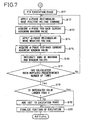
- Fig. 3 describes an algorithm according to which a processor included in control equipment that controls the motor works as the embodiment of a position-of-magnetic-pole detecting device in accordance with the present invention.
- a command that instructs selection of a position-of-magnetic-pole inferring means or method and is sent from a computer numerical control (CNC) system that is an upper-level system of the motor control equipment In response to a command that instructs selection of a position-of-magnetic-pole inferring means or method and is sent from a computer numerical control (CNC) system that is an upper-level system of the motor control equipment, the processing described in Fig. 3 is initiated.
- CNC computer numerical control
- the received command is checked to see if it is a command selecting the first position-of-magnetic-pole inferring means or a command selecting the second position-of-magnetic-pole inferring means (step S1). If selection of the first position-of-magnetic-pole inferring means is instructed, the first position-of-magnetic-pole inference is initiated (step S2).
- step S3 a flag F2 is checked to see if it is set to 1 signifying that the position of a magnetic pole cannot be detected through the second position-of-magnetic-pole inference (step S6). If the flag F2 is not set to 1, a flag F1 is set to 1 signifying that the position of a magnetic pole cannot be detected through the first position-of-magnetic-pole inference (step S7). Processing then proceeds to the second position-of-magnetic-pole inference (a process from step S8 to step S10).
- the flags F1 and F2 are initialized to 0. Moreover, if the rotor moves the first position-of-magnetic-pole inference is executed (step S4), and the position of a magnetic pole is duly finalized (step S5). Steps S2 to S4 in Fig. 3 encircled with a dashed line are steps included in the first position-of-magnetic-pole inference, and will be detailed later.
- step S8 If a command selecting the second position-of-magnetic-pole inferring means is transferred from the upper-level control system, or the first position-of-magnetic-pole inference is in progress, the position of a magnetic pole cannot be detected through the first position-of-magnetic-pole inference because the rotor makes no motion, the flag F1 is set to 1 at step S7. Thereafter, the second position-of-magnetic-pole inference including steps S8 to S10 is initiated (step S8).
- step S9 the flag F1 is checked to see if it is set to 1 (step S11). If the flag F1 is set to 1, it signifies that the first position-of-magnetic-pole inference has already been executed and failed to detect the position of a magnetic pole. Therefore, an alarm is given and processing is terminated (step S13).
- step S12 Processing proceeds to step S1, and the first position-of-magnetic-pole inference is executed.
- the second position-of-magnetic-pole inference proceeds so as to calculate and finalize the position of a magnetic pole (direction of one of magnetic poles and orientation of one of the north and south poles) (steps S10 and S5).
- step S6 If the flag F2 is verified to be set to 1 at step S6, it signifies that the second position-of-magnetic-pole inference has already been performed and failed to detect the position of a magnetic pole. Processing therefore proceeds to step S13, and an alarm is given. The processing is then terminated.
- Fig. 4 and Fig. 5 describes an algorithm defining the first position-of-magnetic-pole inference (including steps S2 to S4 described in Fig. 3 ).
- An initial value of 0 is recorded in a register holding an inferred position of a magnetic pole ⁇ , 0 is recorded as an initial rotor motion value in a register holding a rotor motion value ⁇ , and a value Ir of an initial exciting current is recorded in a register holding an exciting direct current I (steps A1 to A3).
- a current value register holding the position (position of the rotor) of the servo motor (synchronous motor) 4 is cleared to 0 according to a signal sent from the detector 5 (step A4).
- a trial counter n that counts the number of repetitions by which a process from step A6 to step S20 that will be described later is repeated, is set to 1 (step A5).
- the value indicated by the trial counter n is checked to see if it exceeds the predetermined number of repetitions N (step A6). If the counter value does not exceed the predetermined number of repetitions, 360° is divided by 2 n in order to calculate a phase value ⁇ that is a half of a range of phases determining the width of a domain in the rotor where the position of a magnetic pole (position of a magnetic flux) is thought to lie. Initially, the position of a magnetic pole in the rotor is inferred to lie within a domain whose width is determined with the range of electrical angles from 0° to 360°.
- the phase value ⁇ that is a half of the range of phases determining the width of the inferred domain is calculated to be 180° (step S7). Thereafter, the phase value ⁇ that is a half of the range of phases determining the width of the inferred domain, and the rotor motion value ⁇ are added to the position of a magnetic pole inferred at present (one end of the inferred domain, that is, an initial point of the inferred domain lying in the direction of a smaller phase), whereby an excitation phase ⁇ in the stator is calculated (step A8). Initially, as the inferred position of a magnetic pole ⁇ is 0, the phase value ⁇ is 180°, and the rotor motion value ⁇ is 0, the excitation phase ⁇ in the stator is determined to be 180°.
- the rotor is checked to see if it is halted (a fed-back pulse is checked to see if it is returned from the detector 5) (step A9). If the rotor is halted, the dc exciting current I (which initially assumes the set value Ir) recorded in the register is caused to flow in the direction of the excitation phase ⁇ calculated at step A8 (the current command generator 8 shown in Fig. 1 causes the dc exciting current to flow as a command current). At the same time, a timer is started (step A10).
- Whether the rotor has moved is verified based on whether a fed-back pulse is returned from the detector 5 (step A11). If the rotor does not move, an excitation phase is presumably consistent with the position of a magnetic pole. The excitation phase is advanced by 90° and an exciting current is caused to flow in the direction of the excitation phase. Specifically, a flag F3 is checked to see if it is set to 1 (step A21). If the flag F3 is not set to 1, the flag F3 is set to 1 (step A21), and the trial counter n is incremented by one (step A23). The phase value ⁇ is added to the inferred position of a magnetic pole ⁇ , whereby the inferred position of a magnetic pole ⁇ is updated to 180° (step A24).
- step A7 Processing then returns to step A7.
- the trial counter n has been incremented by one to indicate 2. Therefore, the phase value ⁇ is calculated to be 90° and the excitation phase ⁇ is calculated to be 270°. Consequently, the motor is excited in the direction of the excitation phase (steps A7 to A10).
- step A11 As the flag F3 has already been set to 1, detection of the position of a magnetic pole according to the first position-of-magnetic-pole inferring method of detecting the position of a magnetic pole by actuating the rotor is verified to have failed. Processing then proceeds to step S6 in Fig. 3 .
- step A11 the flow of an exciting current is discontinued and the timer is stopped (step A12).
- step A13 The direction of rotation in which the rotor rotates is checked in order to identify a domain in the rotor where the position of a magnetic pole lies (step A13).
- a torque produced with flow of a current through the synchronous motor is expressed as the formula (2).
- the angle ⁇ formed between a magnetic flux vector and a current vector ranges from 0° to 180°
- the direction of the torque is positive (sin ⁇ >0).
- the angle ⁇ ranges from 180° to 360°
- the direction of the torque is negative (sin ⁇ 0). Therefore, when a direct current I is caused to flow in the direction of the excitation phase ⁇ of 180°, if the rotor rotates in the positive direction, the position of a magnetic pole in the rotor lies in a domain determined with a range of excitation phases from 180° to 360°.
- the position of a magnetic pole in the rotor lies in a domain determined with a range of excitation phases from 270° to 360°.
- a phase determining an initial point of a domain where the position of a magnetic pole is inferred to lie is recorded as the inferred position of a magnetic pole ⁇ .
- 180° (or 270°) is recorded as the new inferred position of a magnetic pole ⁇ (step A14).
- the position of a magnetic pole in the rotor lies in a domain determined with a range of excitation phases from 0° to 180° (or 180° to 270°).
- the inferred position of a magnetic pole ⁇ is not updated, but a lower limit of 0° of the range of excitation phases from 0° to 180° determining an initial point of a domain in which the position of a magnetic pole in the rotor is inferred to lie (or a lower limit of 180° of the range of excitation phases from 180° to 270°) is recorded as it is.
- a direct current of opposite polarity, -I is caused to flow in the direction of the excitation phase ⁇ in which the stator is excited at step A10, and the timer is set to an elapsed time measured at step A12 and then started (step A15).
- the timer completes the countdown because the time is up (step A16)
- the flow of the exciting current is discontinued (step A17).
- the exciting current of opposite polarity having the same magnitude is caused to flow for a certain period of time so that the rotor will make a reverse motion corresponding to the motion the rotor has made to return to the original position.
- a phase in the direction of which the direct current I is caused to flow is sequentially approached to the position of a magnetic pole in the rotor so that they will be consistent with each other.
- a magnetic flux vector and a current vector approach each other so that they will be consistent with each other.
- a torque exerted in rotating the rotor is expressed as
- step A6 A process from step A6 to step A20 is repeatedly executed until the trial counter n exceeds the set value N.
- a domain in the rotor where the position of a magnetic pole lie is inferred, and the width of the domain is gradually diminished (in the present embodiment, the width of the domain is halved).
- the inferred position of a magnetic pole ⁇ is detected.
- the phase value ⁇ determining the width of the domain where the position of a magnetic pole lies is as small as 180° or a half of 360°.
- the phase value ⁇ is 90°.
- the phase value ⁇ is 45°.
- the phase value ⁇ is 22.5°.
- the phase value ⁇ is 0.3516°.
- the phase value ⁇ is 0.1758°.
- the lower limit of a range of phases determining the initial point of the domain is accepted as the inferred position of a magnetic pole ⁇ .
- the set value N is determined to provide required precision, the inferred position of a magnetic pole ⁇ with required precision can be obtained.
- step A25 the process proceeds to step A25.
- the rotor motion value ⁇ is added to the inferred position of a magnetic pole ⁇ in order to finalize the inferred position of a magnetic pole ⁇ .
- the process then proceeds to step S5 in Fig. 3 , and the position of a magnetic pole is finalized.
- Fig. 6 and Fig. 7 describe an algorithm defining the second position-of-magnetic-pole inferring method.
- the switch SB shown in Fig. 1 has the contact b thereof made.
- a high-frequency (sine-wave) voltage whose amplitude is relatively small so as not to allow the rotor in the motor to make a motion is transferred as a d-phase voltage command.
- a q-phase voltage command is set to a zero level.
- the motor is thus driven (step B1).
- the voltage command has a high frequency but a small amplitude, the rotor does not move.
- An excitation phase ⁇ is changed by a predetermined magnitude at predetermined intervals (step B2).
- a d-phase fed-back current is read synchronously with the change in the excitation phase ⁇ by the predetermined magnitude (step B3).
- the derivative pi d of the d-phase fed-back current is calculated based on the difference between the read d-phase fed-back current value i d and a d-phase fed-back current value i d read during the previous interval.
- the product f d of the derivative pi d by the high-frequency voltage command transferred at step B1 is calculated (see the formula (6)) (step B4).
- the product f d is subjected to low-pass filtering in order to remove a high-frequency component (see the formula (7)) (step B5).
- the excitation phase ⁇ causing the product f d , which has the high-frequency component thereof removed, to assume a maximum value is detected (step B6).
- a register is included for recording a peak value assumed by the product f d having the high-frequency component thereof removed.
- the product f d calculated at steps B4 and B5 is compared with the value recorded in the register. If the product f d is larger, the calculated product f d value is saved in the register.
- the excitation phase ⁇ causing the product f d to assume the peak value is recorded in a register.
- the process from step B1 to step B6 is executed at predetermined intervals of an electrical angle of 180°.
- step S7 Whether the process to be executed at intervals of the electrical angle of 180° by which one cycle of 360° is divided is repeated a predetermined even number of times (for example, eight times in units of 180° or four times in units of 360°) is verified (step S7). If the process has not been repeated by the predetermined number of times, the process starting at step S1 is resumed. Thus, the excitation phase ⁇ causing the product f d to assume the maximum value within the electrical angle of 180° is determined relative to each of the predetermined number of times or each of the predetermined number of intervals of the electrical angle of 180°.
- step B8 Selecting either of two excitation phases ⁇ causing the product f d to assume the maximum values within one cycle of 360° (for example, a smaller excitation phase ⁇ ) is performed relative to four pairs of determined excitation phases.
- the difference between the largest and smallest values among the selected excitation phases corresponding to electrical angles is checked to see if it falls within a predetermined range. Namely, the selected excitation phases are checked to see if they have differences (step B8).
- the selected excitation phases In case of an electric salient-pole type motor, the selected excitation phases have no differences but fall within the predetermined range. However, in case of a motor that is not of the electric salient-pole type, the selected excitation phases have differences. In this case, the position of a magnetic pole cannot be detected according to the second position-of-magnetic-pole inferring method. Processing therefore proceeds to step S11 in Fig. 3 .
- the selected excitation phases are averaged, and the average is adopted as the excitation phase ⁇ causing the product f d to assume a peak value (step B9).
- the average is corrected in terms of a delay caused by feedback or filtering, whereby the direction of a magnetic flux is determined (step B10). Namely, the excitation phase ⁇ (direction of a magnetic flux) associated with the deviation ⁇ of a magnetic pole from the d-axis which assumes 0 or ⁇ is determined. Thereafter, the orientation of a magnetic pole whose position lies in the direction of the determined excitation phase ⁇ is determined.
- the excitation phase ⁇ is fixed to the direction of a magnetic flux determined at step B10 (step B11).
- a positive rectangular-wave voltage having a predetermined cycle and a relatively large magnitude is applied as a d-phase voltage command so that a current large enough to cause magnetic saturation will flow through the motor for the purpose of driving the motor (step B12).
- the excitation phase is consistent with the direction of the d-axis, even if the large current flows, the rotor included in the motor makes no motion.
- the peak value (maximum value) of a d-phase fed-back current is measured and recorded (step B13).
- a rectangular-wave voltage having an opposite sign (negative voltage) but having the same magnitude is applied as a d-phase voltage command in order to drive the motor (step B14). Even in this case, the rotor in the motor does not rotate.
- the peak value (minimum value) of the d-phase fed-back current is measured and recorded (step B15).
- step B16 The maximum value and minimum value of the peak values assumed by the d-phase fed-back current and measured at step B12 and B14 respectively are added up, and the thus obtained sums are integrated (step B16). Whether the calculation has been executed a predetermined number of times is verified. If the calculation has not been executed the predetermined number of times, processing returns to step B12, and the foregoing process starting at step B12 is repeatedly executed (step B17). After the peak values (maximum and minimum values) of the d-phase fed-back current are measured and added up the predetermined number of times, the resultant sums are integrated. Thereafter, the integrated value is checked to see if it is positive or negative (step B18).
- the direction of the excitation phase ⁇ and the orientation of the magnetic pole are consistent with each other.
- the current excitation phase ⁇ is regarded to be consistent with the direction of a main magnetic flux and is associated with the deviation ⁇ of 0, and determined as a position of excitation ⁇ (step B20).
- the direction of the current excitation phase is opposite to the direction of a main magnetic flux and is associated with the deviation ⁇ of ⁇ . Therefore, 180° is added to the current excitation phase ⁇ (step B19), and a position lying in the direction of the resultant angle is finalized as the position of excitation ⁇ (step B20). Processing then returns to step S5 in Fig. 3 .
- the position-of-magnetic-pole detecting method in accordance with the present embodiment has been described so far. Consequently, if it is impossible to detect the position of a magnetic pole by actuating a rotor because friction against a machine is too great, the second position-of-magnetic-pole inferring method is adopted. As long as a motor has the electrical characteristic of a salient-pole type, the position of a magnetic pole can be detected according to the second position-of-magnetic-pole inferring method. Moreover, when a motor is of a non-salient pole type, the position of a magnetic pole is detected according to the first position-of-magnetic-pole inferring method of detecting the position of a magnetic pole by actuating a rotor.
- the second position-of-magnetic-pole inferring method is automatically adopted. If the position of a magnetic pole cannot be detected according to the second position-of-magnetic-pole inferring method, the first position-of-magnetic-pole inferring method is automatically adopted. Only when the position of a magnetic pole cannot be detected according to both the first and second position-of-magnetic-pole inferring methods, an alarm is given.
- the present invention has the advantages described below. Since the first position-of-magnetic-pole inferring means autonomously detects the position of a magnetic pole by actuating the motor, the position of a magnetic pole in the synchronous motor can be automatically detected irrespective of whether the motor has the electrical characteristic of a salient-pole type. Moreover, if the first position-of-magnetic-pole inferring means fails to detect the position of a magnetic pole because the motor makes no motion due to great friction against a machine, as long as the synchronous motor has the electrical characteristic of a salient-pole type, the second position-of-magnetic-pole inferring means can autonomously detect the position of a magnetic pole. A case where the position of a magnetic pole in a synchronous motor cannot automatically be detected is quite rare.
Landscapes
- Engineering & Computer Science (AREA)
- Power Engineering (AREA)
- Control Of Motors That Do Not Use Commutators (AREA)
- Control Of Ac Motors In General (AREA)
- Control Of Stepping Motors (AREA)
- Control Of Electric Motors In General (AREA)
Claims (3)
- Magnetpol-Position-Erfassungseinrichtung zum Erfassen einer Position eines Magnetpols in einem Rotor, der in einem Synchronmotor (4) enthalten ist, wobei die Erfassungseinrichtung umfasst:ein Stromanweisungsausführungsmittel (8) zum Ausführen einer Stromanweisung in Richtung einer vorgegebenen Erregungsphase (ψ);ein erstes Magnetpol-Position-Bestimmungsmittel (7) zum Bestimmen eines Bereichs, in dem eine Position eines Magnetpols liegt und welcher hiervon die Breite aufweist, welche durch einen Bereich elektrischer Winkel bestimmt ist, anhand der Rotationsrichtung, in die sich der Motor (4) dreht, der auf die Stromanweisung reagiert, und der Erregerphase (ψ), wobei der Bereich sich verkleinert und somit die Position eines Magnetpols bestimmt wird, wobei die Magnetpol-Position-Erfassungseinrichtung dadurch gekennzeichnet ist, dass sie weiterhin umfasst:ein Spannungsanweisungsausführungsmittel (9) zum Ausführen einer Spannungsanweisung in Richtung der vorgegebenen Erregerphase (ψ);ein zweites Magnetpol-Position-Bestimmungsmittel zum Bestimmen der Position eines Magnetpols anhand eines Rückkopplungsstroms, der auf die Spannungsanweisung reagierend erwidert, welche durch die sequentiell geänderten Erregerphase (ψ) ausgeführt wird, wobei eine Spannung angelegt ist, die groß genug ist, um eine magnetische Sättigung zu bewirken, um die Ausrichtung eines Magnetpols zu bestimmen, und somit die Position eines Magnetpols zu bestimmen, undein Mittel (SA, SB) zum Auswählen eines der ersten und zweiten Magnetpol-Position-Bestimmungsmittel (7), welche die Position eines Magnetpols bestimmen.
- Magnetpol-Position-Erfassungseinrichtung nach Anspruch 1, wobei wenngleich eine Stromanweisung ausgeführt wird, so dass das erste Magnetpol-Position-Bestimmungsmittel (7) die Position eines Magnetpols bestimmen wird, dann, wenn der Motor (4) sich nicht dreht, das Mittel (SA, SB) zum Auswählen eines der ersten und zweiten Magnetpol-Position-Bestimmungsmittel das zweite Position-eines-Magnetpols-Bestimmungsmittel selbständig auswählt.
- Magnetpol-Position-Erfassungseinrichtung nach Anspruch 1, wobei eine Differenz zwischen den Positionen eines Magnetpols, die durch das zweite Magnetpol-Position-Bestimmungsmittel bestimmt werden, einen vorgegebenen Bereich überschreitet und das Mittel (SA, SB) zum Auswählen eines der ersten und zweiten Magnetpol-Position-Bestimmungsmittel (7) das erste Magnetpol-Position-Bestimmungsmittel (7) selbständig auswählt.
Applications Claiming Priority (2)
| Application Number | Priority Date | Filing Date | Title |
|---|---|---|---|
| JP2003388384 | 2003-11-18 | ||
| JP2003388384A JP3971741B2 (ja) | 2003-11-18 | 2003-11-18 | 磁極位置検出装置 |
Publications (4)
| Publication Number | Publication Date |
|---|---|
| EP1533891A2 EP1533891A2 (de) | 2005-05-25 |
| EP1533891A8 EP1533891A8 (de) | 2005-07-27 |
| EP1533891A3 EP1533891A3 (de) | 2007-05-16 |
| EP1533891B1 true EP1533891B1 (de) | 2012-01-04 |
Family
ID=34431555
Family Applications (1)
| Application Number | Title | Priority Date | Filing Date |
|---|---|---|---|
| EP04026932A Ceased EP1533891B1 (de) | 2003-11-18 | 2004-11-12 | Vorrichtung zur Positionserfassung der magnetischen Pole |
Country Status (4)
| Country | Link |
|---|---|
| US (1) | US7170283B2 (de) |
| EP (1) | EP1533891B1 (de) |
| JP (1) | JP3971741B2 (de) |
| CN (1) | CN1314194C (de) |
Families Citing this family (27)
| Publication number | Priority date | Publication date | Assignee | Title |
|---|---|---|---|---|
| WO2003067748A1 (fr) * | 2002-02-07 | 2003-08-14 | Mitsubishi Denki Kabushiki Kaisha | Dispositif de detection de pole magnetique d'un moteur ca synchrone et procede de detection de pole magnetique associe |
| JP4716118B2 (ja) * | 2006-03-29 | 2011-07-06 | 株式会社ジェイテクト | モータ制御装置 |
| JP2007336641A (ja) * | 2006-06-13 | 2007-12-27 | Denso Corp | 同期モータの位置センサレス駆動装置 |
| US7622882B2 (en) * | 2006-08-21 | 2009-11-24 | Magna Electronics Inc. | Position detection device for permanent magnetic machines |
| GB0702975D0 (en) * | 2007-02-15 | 2007-03-28 | Switched Reluctance Drives Ltd | Control of an electrical machine |
| WO2008120580A1 (ja) * | 2007-03-28 | 2008-10-09 | Kabushiki Kaisha Yaskawa Denki | モータ制御装置と磁極位置推定精度確認方法 |
| JP5370677B2 (ja) * | 2007-10-12 | 2013-12-18 | 株式会社安川電機 | モータ制御装置 |
| JP5104213B2 (ja) * | 2007-10-29 | 2012-12-19 | 富士電機株式会社 | 永久磁石形同期電動機の制御装置 |
| JP5327503B2 (ja) * | 2008-02-05 | 2013-10-30 | 株式会社ジェイテクト | モータ制御装置 |
| KR101135733B1 (ko) * | 2008-04-09 | 2012-04-16 | 미쓰비시덴키 가부시키가이샤 | 자극 위치 검출 장치 및 방법 |
| DE102008001408A1 (de) | 2008-04-28 | 2009-10-29 | Robert Bosch Gmbh | Offsetwinkelbestimmung bei Synchronmaschinen |
| KR101475647B1 (ko) * | 2011-06-27 | 2014-12-22 | 미쓰비시덴키 가부시키가이샤 | 회전기의 제어 장치 |
| DE102012204751B4 (de) * | 2012-03-26 | 2018-12-20 | Robert Bosch Gmbh | Verfahren zur Überprüfung einer Erregerstrommessung einer Synchronmaschine im Generatorbetrieb |
| JP5357300B1 (ja) | 2012-05-21 | 2013-12-04 | ファナック株式会社 | 永久磁石同期電動機におけるロータの磁極位置を検出する磁極位置検出装置 |
| GB2503039B (en) | 2012-06-15 | 2020-05-27 | Danfoss Drives As | Method for controlling a synchronous reluctance electric motor |
| GB2503040B (en) * | 2012-06-15 | 2020-05-06 | Danfoss Drives As | Variable torque angle for electric motor |
| JP5667153B2 (ja) * | 2012-12-03 | 2015-02-12 | ファナック株式会社 | 同期電動機の磁極位置検出装置 |
| JP5820446B2 (ja) * | 2013-09-13 | 2015-11-24 | Thk株式会社 | リニアモータの制御装置、及び制御方法 |
| JP6021784B2 (ja) * | 2013-10-23 | 2016-11-09 | 三菱電機株式会社 | 同期回転機の磁極位置検出方法 |
| CN108063572B (zh) * | 2017-12-01 | 2020-03-03 | 浙江零跑科技有限公司 | 一种车用永磁电机位置传感器失效控制方法 |
| CN108631660B (zh) * | 2018-03-30 | 2020-04-10 | 江苏美的清洁电器股份有限公司 | 无刷直流电机的转子定位方法、定位装置和控制系统 |
| CN108712128B (zh) * | 2018-06-07 | 2021-10-01 | 南京信息职业技术学院 | 一种克服了摩擦力影响的交流伺服系统的对相方法 |
| JP7159704B2 (ja) * | 2018-08-31 | 2022-10-25 | 株式会社アドヴィックス | モータ制御装置 |
| US11303239B2 (en) * | 2018-10-12 | 2022-04-12 | Fanuc Corporation | Magnetic pole initial position detection device using direct-current excitation method and magnetic pole position detection device |
| JP7323410B2 (ja) * | 2019-10-01 | 2023-08-08 | 株式会社日立ハイテク | 搬送装置、および分析システム |
| JP7364436B2 (ja) * | 2019-11-21 | 2023-10-18 | ファナック株式会社 | 磁極方向検出装置および磁極方向検出方法 |
| DE112021001327T5 (de) | 2020-02-26 | 2023-03-16 | Fanuc Corporation | Magnetpolpositionsdetektionsvorrichtung |
Family Cites Families (13)
| Publication number | Priority date | Publication date | Assignee | Title |
|---|---|---|---|---|
| US5903128A (en) * | 1996-02-01 | 1999-05-11 | Denso Corporation | Sensorless control system and method of permanent magnet synchronous motor |
| JP2000175483A (ja) * | 1998-10-02 | 2000-06-23 | Kobe Steel Ltd | 同期電動機のセンサレス制御方法及びその装置 |
| JP4211133B2 (ja) * | 1999-04-26 | 2009-01-21 | 株式会社明電舎 | 永久磁石式同期電動機のセンサレス制御システム |
| JP3408468B2 (ja) * | 1999-09-07 | 2003-05-19 | ファナック株式会社 | 同期電動機のロータ磁極位置検出方法 |
| JP2002078391A (ja) | 2000-08-30 | 2002-03-15 | Hitachi Ltd | 交流電動機の駆動システム |
| JP4596200B2 (ja) | 2000-11-27 | 2010-12-08 | 富士電機システムズ株式会社 | 永久磁石形同期電動機の制御装置 |
| JP4867067B2 (ja) | 2000-12-04 | 2012-02-01 | 富士電機株式会社 | 永久磁石形同期電動機の制御装置 |
| JP4687846B2 (ja) * | 2001-03-26 | 2011-05-25 | 株式会社安川電機 | 同期電動機の磁極位置推定方法および制御装置 |
| JP4665360B2 (ja) | 2001-08-06 | 2011-04-06 | 株式会社安川電機 | 電動機制御装置 |
| JP2003061385A (ja) * | 2001-08-13 | 2003-02-28 | Matsushita Electric Ind Co Ltd | 永久磁石同期モータの位置センサレス制御装置 |
| JP3982232B2 (ja) * | 2001-10-25 | 2007-09-26 | 株式会社日立製作所 | 同期発電機のセンサレス制御装置と制御方法 |
| ITMI20012835A1 (it) * | 2001-12-28 | 2003-06-28 | Abb Service Srl | Procedimento per la determinazione della posizione del rotore di una macchina sincrona a corrente alternata a magneti permanenti |
| JP3805336B2 (ja) * | 2003-10-22 | 2006-08-02 | ファナック株式会社 | 磁極位置検出装置及び方法 |
-
2003
- 2003-11-18 JP JP2003388384A patent/JP3971741B2/ja not_active Expired - Fee Related
-
2004
- 2004-11-12 US US10/986,201 patent/US7170283B2/en not_active Expired - Lifetime
- 2004-11-12 EP EP04026932A patent/EP1533891B1/de not_active Ceased
- 2004-11-17 CN CNB2004100957527A patent/CN1314194C/zh not_active Expired - Fee Related
Also Published As
| Publication number | Publication date |
|---|---|
| EP1533891A8 (de) | 2005-07-27 |
| JP2005151752A (ja) | 2005-06-09 |
| US7170283B2 (en) | 2007-01-30 |
| EP1533891A2 (de) | 2005-05-25 |
| JP3971741B2 (ja) | 2007-09-05 |
| EP1533891A3 (de) | 2007-05-16 |
| CN1314194C (zh) | 2007-05-02 |
| US20050104582A1 (en) | 2005-05-19 |
| CN1619939A (zh) | 2005-05-25 |
Similar Documents
| Publication | Publication Date | Title |
|---|---|---|
| EP1533891B1 (de) | Vorrichtung zur Positionserfassung der magnetischen Pole | |
| EP1526635B1 (de) | Detektionseinrichtung, und -verfahren zur Detektion der Position von Magnet-Polen | |
| JP5866429B2 (ja) | 電気機器を制御する方法及び装置 | |
| EP2579448B1 (de) | Bestimmung der Rotorposition in sensorlosen geschalteten Reluktanzmotoren | |
| JP4211133B2 (ja) | 永久磁石式同期電動機のセンサレス制御システム | |
| US9673739B2 (en) | Machine type identification | |
| JP2008220096A (ja) | 同期電動機のセンサレス制御装置 | |
| US20080258660A1 (en) | Method for detecting initial magnetic pole position in permanent-magnet motor | |
| JP5743344B2 (ja) | 同期電動機の制御装置 | |
| KR20200059849A (ko) | Bldc 모터 과부하 감지 장치 및 방법 | |
| JP2017055637A (ja) | モータの巻き線に生じる逆起電圧に基づきモータを制御するモータ制御装置 | |
| KR20200059848A (ko) | Bldc 모터 과부하 감지 장치 및 방법 | |
| KR101225165B1 (ko) | 센서리스 영구자석 동기모터의 기동제어방법 | |
| US7067997B2 (en) | Method for determining rotor position angle of synchronous machine | |
| KR20180028802A (ko) | 모터 회전자 제어 장치 및 방법 | |
| JP3405115B2 (ja) | 電動機の電気角偏差の測定方法 | |
| JPH0866082A (ja) | 永久磁石形同期電動機の回転子磁極極性検出法 | |
| JP2008005646A (ja) | 永久磁石式同期電動機の初期磁極位置推定装置 | |
| EP3783794B1 (de) | Verfahren und vorrichtung zur erkennung der magnetpolposition eines rotors in einem einphasigen bldc-motor | |
| CN114079408B (zh) | 电动机的初始位置检测 | |
| JP3979102B2 (ja) | 電動機の制御方法およびその制御装置 | |
| JP2013042662A (ja) | モータ磁極位相の調整方法 | |
| KR20180029355A (ko) | 모터 회전자 제어 장치 및 방법 |
Legal Events
| Date | Code | Title | Description |
|---|---|---|---|
| PUAI | Public reference made under article 153(3) epc to a published international application that has entered the european phase |
Free format text: ORIGINAL CODE: 0009012 |
|
| AK | Designated contracting states |
Kind code of ref document: A2 Designated state(s): AT BE BG CH CY CZ DE DK EE ES FI FR GB GR HU IE IS IT LI LU MC NL PL PT RO SE SI SK TR |
|
| AX | Request for extension of the european patent |
Extension state: AL HR LT LV MK YU |
|
| RIN1 | Information on inventor provided before grant (corrected) |
Inventor name: TOYOZAWA, YUKIO Inventor name: SONODA, NAOTO |
|
| PUAL | Search report despatched |
Free format text: ORIGINAL CODE: 0009013 |
|
| AK | Designated contracting states |
Kind code of ref document: A3 Designated state(s): AT BE BG CH CY CZ DE DK EE ES FI FR GB GR HU IE IS IT LI LU MC NL PL PT RO SE SI SK TR |
|
| AX | Request for extension of the european patent |
Extension state: AL HR LT LV MK YU |
|
| RIC1 | Information provided on ipc code assigned before grant |
Ipc: H02P 1/46 20060101ALI20070411BHEP Ipc: H02P 21/00 20060101ALI20070411BHEP Ipc: H02P 6/16 20060101AFI20050223BHEP |
|
| 17P | Request for examination filed |
Effective date: 20070613 |
|
| AKX | Designation fees paid |
Designated state(s): DE |
|
| 17Q | First examination report despatched |
Effective date: 20100831 |
|
| RAP1 | Party data changed (applicant data changed or rights of an application transferred) |
Owner name: FANUC CORPORATION |
|
| GRAP | Despatch of communication of intention to grant a patent |
Free format text: ORIGINAL CODE: EPIDOSNIGR1 |
|
| GRAS | Grant fee paid |
Free format text: ORIGINAL CODE: EPIDOSNIGR3 |
|
| GRAA | (expected) grant |
Free format text: ORIGINAL CODE: 0009210 |
|
| AK | Designated contracting states |
Kind code of ref document: B1 Designated state(s): DE |
|
| REG | Reference to a national code |
Ref country code: DE Ref legal event code: R096 Ref document number: 602004035942 Country of ref document: DE Effective date: 20120301 |
|
| PLBE | No opposition filed within time limit |
Free format text: ORIGINAL CODE: 0009261 |
|
| STAA | Information on the status of an ep patent application or granted ep patent |
Free format text: STATUS: NO OPPOSITION FILED WITHIN TIME LIMIT |
|
| 26N | No opposition filed |
Effective date: 20121005 |
|
| REG | Reference to a national code |
Ref country code: DE Ref legal event code: R097 Ref document number: 602004035942 Country of ref document: DE Effective date: 20121005 |
|
| PGFP | Annual fee paid to national office [announced via postgrant information from national office to epo] |
Ref country code: DE Payment date: 20210929 Year of fee payment: 18 |
|
| REG | Reference to a national code |
Ref country code: DE Ref legal event code: R119 Ref document number: 602004035942 Country of ref document: DE |
|
| PG25 | Lapsed in a contracting state [announced via postgrant information from national office to epo] |
Ref country code: DE Free format text: LAPSE BECAUSE OF NON-PAYMENT OF DUE FEES Effective date: 20230601 |