EP1533763A1 - Spielautomat - Google Patents
Spielautomat Download PDFInfo
- Publication number
- EP1533763A1 EP1533763A1 EP04003874A EP04003874A EP1533763A1 EP 1533763 A1 EP1533763 A1 EP 1533763A1 EP 04003874 A EP04003874 A EP 04003874A EP 04003874 A EP04003874 A EP 04003874A EP 1533763 A1 EP1533763 A1 EP 1533763A1
- Authority
- EP
- European Patent Office
- Prior art keywords
- display means
- player
- stop
- game
- variable display
- Prior art date
- Legal status (The legal status is an assumption and is not a legal conclusion. Google has not performed a legal analysis and makes no representation as to the accuracy of the status listed.)
- Ceased
Links
Images


Classifications
-
- G—PHYSICS
- G07—CHECKING-DEVICES
- G07F—COIN-FREED OR LIKE APPARATUS
- G07F17/00—Coin-freed apparatus for hiring articles; Coin-freed facilities or services
- G07F17/32—Coin-freed apparatus for hiring articles; Coin-freed facilities or services for games, toys, sports, or amusements
- G07F17/3202—Hardware aspects of a gaming system, e.g. components, construction, architecture thereof
- G07F17/3204—Player-machine interfaces
- G07F17/3211—Display means
-
- G—PHYSICS
- G07—CHECKING-DEVICES
- G07F—COIN-FREED OR LIKE APPARATUS
- G07F17/00—Coin-freed apparatus for hiring articles; Coin-freed facilities or services
- G07F17/32—Coin-freed apparatus for hiring articles; Coin-freed facilities or services for games, toys, sports, or amusements
- G07F17/34—Coin-freed apparatus for hiring articles; Coin-freed facilities or services for games, toys, sports, or amusements depending on the stopping of moving members in a mechanical slot machine, e.g. "fruit" machines
Definitions
- the present invention relates to a gaming machine such as a slot machine or a Japanese pinball machine (a so-called “pachinko machine", which will be simply referred to as “pinball machine”) including a variable display means for variably displaying various symbols provided for playing a game and control means such as a microcomputer for controlling the variable display.
- a gaming machine such as a slot machine or a Japanese pinball machine (a so-called “pachinko machine”, which will be simply referred to as “pinball machine")
- a variable display means for variably displaying various symbols provided for playing a game
- control means such as a microcomputer for controlling the variable display.
- FIG. 38 shows a conventional pinball slot machine X.
- the pinball slot machine X has a variable display means having the configuration wherein three rotation reels 104 to 106 for producing variable display of a plurality of symbols are disposed in display windows 101 to 103 provided in a front panel 100 and reel stop buttons 107 to 109 for stopping the rotation reels 104 to 106 are provided. When a predetermined symbol combination becomes complete through the variable display means, the player gains a prize.
- Printed on the front of the front panel 100 are a one-medal pay line 111 at the middle stage which becomes activated with one medal inserted, two two-medal pay lines 112a an 112b which become activated with two medals inserted, and two three-medal pay lines 113a an 113b which become activated with three medals inserted for nine symbols (three columns X three rows) displayed through the display windows 101 to 103.
- numeral 114 denotes a game medium (medal, coin, or the like) slot
- numeral 115 denotes a start lever for starting a game.
- a variable display means having a screen such as a liquid crystal screen on which variable display of symbols can be produced is also available.
- control means controls the variable display means for rotating the reels 104 to 106, thereby producing variable display of symbols.
- the rotating reels 104 to 106 are stopped in order automatically in a given time or as the player operates the reel stop buttons 107 to 109. At this time, if the symbols on the reels 104 to 106 appearing in the display windows 101 to 103 become a specific combination (winning symbol combination), game play media are payout to the player as the prize of the win.
- the pinball slot machine X has different winning game states. Particularly, in some pinball slot machines, when the winning game of a predetermined winning combination is complete, the player is placed in a game state in which the player is given a better condition than the usual state for a predetermined time period in addition to paying out a predetermined number of medals.
- winning combinations include a winning combination for allowing the player to play a predetermined number of games giving a relatively large prize to the player, which will be hereinafter referred to as big bonus (BB), and a winning combination for allowing the player to play a predetermined number of games giving a relatively small prize to the player, which will be hereinafter referred to as regular bonus (RB).
- internal lottery processing (simply, internal lottery) is performed and the symbol combination stopped and displayed along the line of the pay lines 111 to 113 made activated, which will be hereinafter referred to as activated line, is determined based on the lottery result and the stop operation timing of the reel stop buttons 107 to 109 by the player. That is, to complete a winning game for paying out medals or coins to the player, it is required that the winning combination be won according to the internal lottery processing, which will be hereinafter referred to as internal winning, and that the player perform stop operation at the timing at which the symbol combination indicating completion of the winging game of the winning combination gaining the internal winning, which will be hereinafter referred to as symbol combination, can be stopped on the activated line.
- an optically transparent information display panel including a matrix display unit that can display a dot pattern with a plurality of rows and a plurality of columns of dots is provided at the rear of a front panel or in the proximity of the rear of the front panel and moreover the information display panel is implemented as a transparent EL (electroluminescent) panel for displaying optically transparent characters and symbols in dot patterns.
- JP-A-2000-350805 which includes the information display panel, it is made possible to produce extensive display containing an effect image.
- the symbols on the reels are always seen through the dot patterns and incomplete display of the effortful effect image and the symbols on the reels easily results; sharp contrast is not provided between the effect image and the symbols on the reels is always transparent-displayed and it is feared that the player may get tired of playing games on the gaming machine.
- a gaming machine including: variable display means for variably displaying a plurality of symbols; symbol combination determination means configured to determine a symbol combination; stop control means configured to stop at least one of the symbols of the variable display means based on the determination result of the symbol combination determination means; game medium payout means configured to pay out a game medium to a player in a case where a stop state of the variable display means stopped by the stop control means corresponds to a predetermined stop state; front display means provided in front of the variable display means and configured to enable the player to see at least one of the symbols of the variable display means therethrough, and to display various images; and front display moving means configured to move the front display means.
- the front display means may be able to be moved in the back and forth direction with respect to the variable display means.
- the front display means may be able to be moved in the up and down direction with respect to the variable display means.
- the front display means may be able to be switched between a position where the player can visually recognize the front display means and a position where the player cannot visually recognize the front display means.
- a gaming machine of the invention has variable display means for producing variable display of a plurality of symbols, front display means being provided in front of the variable display means for enabling the player to see symbols on the variable display means through the front display means, symbol combination determination means for determining a symbol combination, a plurality of operation means for the player to stop the variable display of the variable display means, stop control means for performing stop control of the variable display operation of the variable display means based on the determination result of the symbol combination determination means and operation input to the operation means, and game medium payout means for paying out game play media to the player if the stop state of the variable display means stopped by the stop control means is a predetermined stop state, wherein the front display means can be moved.
- the front display means By moving the front display means, sharp contrast can be provided between the effect produced by the variable display means and the effect produced by the front display means. For example, when the effect is produced by the variable display means, the front display means is moved to a position where the player cannot visually recognize the front display means, so that player's interest can be excited in the effect produced by the variable display means. When the effect is produced by the front display means, the front display means can be moved to the ahead position of the variable display means for exciting player's interest in the effect produced by combining the effect produced by the front display means and the effect produced by the variable display means.
- the front display means can also be moved up and down, from side to side, or back and forth, whereby change can be given to the effect and player's interest can be still more excited in the effect.
- the player can select the effect produced by the front display means or the effect produced by the variable display means for visually checking the effect with the accent put on the effect produced by either means, whereby the player can be made to enjoy the effect produced by either means with the accent put thereon.
- the front display means is moved backward relative to the variable display means (if the front display means and the variable display means are brought close to each other) , the player can visually check the effect produced by the front display means and the effect produced by the variable display means at the same time, whereby the player can be made to enjoy the effect produced by combining the effects of both of the means.
- the superposition state of the effect produced by the front display means and the effect produced by the variable display means changes and change can be given to the effect produced by combining the effects of both of the means, making the player enjoy the effect.
- the player can visually check the effect produced by the front display means and the effect produced by the variable display means at the same time, and can be made to enjoy the effect produced by combining the effects of both of the means.
- the front display means is moved to a position where the player cannot visibly recognize the front display means, the effect produced by the variable display means becomes easy to see and the player can be made to enj oy the effect produced by the variable display means.
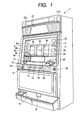
- FIG. 1 is a perspective view to show the appearance of a gaming machine 1 of a first embodiment according to the invention.
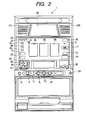
- FIG. 2 is a front view of the gaming machine 1 of a first embodiment according to the invention.
- the gaming machine 1 is a so-called "pinball slot machine” including three rotation reels for producing variable display of symbols and allows the player to play a game using game play media such as a card storing information of the game play value given to the player as well as coins, medals or tokens. In the description that follows, it is assumed that the player uses medals.
- a panel display unit 5 of a liquid crystal display is provided at the front of a cabinet 2 forming the whole of the gaming machine 1.
- three rotation reels 3L, 3C, and 3R each with a symbol row made up of different types of symbols drawn on the outer peripheral surface are provided in a row for rotation for providing variable display means.
- the player can observe the symbols on the reels through display windows 4L, 4C, and 4R seen through the panel display unit 5.
- Each reel rotates at a constant speed (for example, 80 revolutions per minute).
- the panel display unit 5 is provided fully with a screen 5a for forming front display means through which the rotation reels 3L, 3C, and 3R can be seen. When viewed from the player, the following components appear.
- the vertically oriented rectangular display windows 4L, 4C, and 4R are seen at the center of the display screen 5a, and a center line 8a, a top line 8b, and a bottom line 8c in the horizontal direction and a cross down line 8d and cross up line 8e in the slanting directions as pay lines are visible in the display windows 4L, 4C, and 4R.
- As the pay lines one, three, or five lines are made activated as the player operates a 1-BET switch 11, a 2-BET switch 12, or a MAX-BET switch 13 (described later) or inserts medals into a medal insertion slot 22. Which pay lines are made activated is indicated as the corresponding lines are lighted and a BET lamp 9a, 9b, or 9c (described below) is lighted.
- the 1-BET lamp 9a, the 2-BET lamp 9b, the MAX-BET lamp 9c, and a deposited-number-of-game-play-medals display unit 19 are provided on the left of the display windows 4L, 4C, and 4R.
- the 1-BET lamp 9a, the 2-BET lamp 9b, or the MAX-BET lamp 9c is lighted in response to the number of medals bet to play one game, which will be hereinafter referred to as the BET count. In the embodiment, one game is over when all reels stop or when game play media have been payout if game play media are payout.
- the 1-BET lamp 9a When the BET count is 1 and one pay line is made activated, the 1-BET lamp 9a is lighted; when the BET count is 2 and three pay lines are made activated, the 2-BET lamp 9b is lighted; and when the BET count is 3 and all the five pay lines are made activated, the MAX-BET lamp 9c is lighted.
- a game play start indicator lamp 25 provided below the SET lamps 9a, 9b, and 9c is lighted when at least one pay line is made activated. Further, the deposited-number-of-game-play-medals display unit 19 displays the deposited number of medals.
- a WIN lamp 17, a payout display unit 18, and a game play medal insertion lamp 24 are provided on the right of the display windows 4L, 4C, and 4R.
- the WIN lamp 17 is lighted at a predetermined probability when the internal winning is accepted as BB or RB.
- the WIN lamp 17 is also lighted when the winning game of BB or RB is complete.
- the payout display unit 18 is made up of seven-segment LEDs for displaying the number of medals payout when the winning game is complete.
- the game play medal insertion lamp 24 is blinked when insertion of game play medals can be accepted.
- a number-of-bonus-game-operation-times display unit 20 is provided in the upper right corner of the display screen 5a.
- the number-of-bonus-game-operation-times display unit 20 displays the number of RB games that can be played, and the possible number of winning games of RB (described later).
- a game play stop indicator 31, a replay indicator 32, an RB operation indicator 33, and a BB operation indicator 34 are provided in a row in the upper left corner of the display screen 5a.
- the game play stop indicator 31 is lighted when the time interval between the preceding drum rotation and the current drum rotation is less than a predetermined time (in the embodiment, 4.1 seconds).
- the replay indicator 32 is lighted when replay is operated.
- the RB operation indicator 33 is lighted during the RB operation.
- the BB operation indicator 34 is lighted during the BB operation.
- the display screen 5a also displays the "stop order" required for realizing completion of the winning game when the internal winning of "small prize of bell” is accepted in "stop operation assistance time period” (described later).
- a frontward projection portion 10 of a horizontal plane is formed below the display windows 4L, 4C, and 4R seen through the display screen 5a, and an indication section 2a for indicating information concerning the gaming machine 1 is provided between the frontward projection portion 10 and the display windows 4L, 4C, and 4R.
- a medal insertion slot 22 is provided on the right of the indication section 2a, and the 1-BET switch 11, the 2-BET switch 12, and the MAX-BET switch 13 are provided at the lower position to the left of the indication section 2a.
- a cross button 26, a "O” button 27, and a "X” button 28 are provided at the upper position to the left of the indication section 2a.
- the 1-BET switch 11 enables the player to bet one of the credited medals by one push operation on a game.
- the 2-BET switch 12 enables the player to bet two of the credited medals by one push operation on a game.
- the MAX-BET switch 13 enables the player to bet as many medals as the maximum number of medals that can be bet on a game by one push operation. As the player operates any of the BET switches, the corresponding pay lines are made activated as described above.
- the player can switch the display screen 5a and make entry by operating the cross button 26, the "O" button 27, and the "X" button 28.
- a deposited medal adjusting switch 14 for the player to switch between credit and payout of the medals obtained by playing games by pushbutton operation is provided on the left of the front of the frontward projection portion 10. As the deposited medal adjusting switch 14 is switched, medals are payout from a game play medal payout opening 15 in a lower part of the front and are stored in a game play medal tray 16. On the right of the depositedmedal adjusting switch 14, a start lever 6 for rotating the reels for starting variable display of symbols in the display windows 4L, 4C, and 4R (starting a game) as the player operates the start lever 6 is attached so that it can be turned in a predetermined angle range.
- a door opening/closing and closing release device 29 is provided to the right of the front of the frontward projection portion 10. As the door opening/closing and closing release device 29 is turned to the right with a predetermined key, the front door is opened/closed; as the device 29 is turned to the left, closing is released.
- Speakers 21L and 21R are provided on the upper left and right of the cabinet 2, and a payout table panel 23 for displaying winning symbol combination, the number of payout medals, and the like is provided between the two speakers 21L and 21R.
- Three stop buttons 7L, 7C, and 7R for stopping rotation of the three rotation reels 3L, 3C, and 3R are provided at the center of the front of the frontward projection portion 10 and below the indication section 2a.
- the panel display unit 5 is attached to a front opening 2b of the cabinet 2 so as to face from the back of the front opening 2b, and the portion exposed from the cabinet 2 forms the display screen 5a.
- the panel display unit 5 is attached to the rear of the cabinet 2 so that it can move in the back and forth direction relative to the rotation reels 3L, 3C, and 3R through a motorized cylinder 2c.
- numeral 2d denotes a guide.
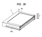
- the panel display unit 5 is implemented as a multi-layer panel body 5' clamped and held by a rectangular frame 505, as shown in FIG. 36.
- the multi-layer panel body 5' has a multi-layer structure made up of, from the outermost side (front), transparent protective glass 500 and a liquid crystal panel 501 substantially making up the front display means, a light guide plate 503 made of an acrylic material having a predetermined thickness forming a part of a backlight structure, and a diffuser panel 504 made of a plastic film put on the rear of the light guide plate 503.
- the diffuser panel 504 is formed on the surface with asperities for irregularly reflecting and diffusing light.
- a transparent acrylic plate may be used in place of the protective glass 500.
- a backlight is disposed between the front display means and the variable display means for applying backlight to the symbols on the variable display means. That is, a cold-cathode tube 2e for functioning as the backlight of the liquid crystal panel 501 and being capable of applying light to the symbols on the rotation reels 3L, 3C, and 3R is disposed between the multi-layer panel body 5' and the rotation reels 3L, 3C, and 3R and at a lower position of the multi-layer panel body 5'.
- the cold-cathode tube 2e is faced to the lower end part of the light guide plate 503 and the frame 505 is formed with a notch 505a for allowing light to pass through, so that light can pass through the end part of the light guide plate 503 to the whole and can be diffused forward by the diffuser panel 504 for the cold-cathode tube 2e to function as the backlight of the liquid crystal panel 501 and a liquid crystal shutter 502.
- a part of light of the cold-cathode tube 2e is applied to the rotation reels 3L, 3C, and 3R disposed at the rear of the multi-layer panel body 5'.
- numeral 2f denotes a reflection cover disposed so as to involve the cold-cathode tube 2e.
- the reflection cover 2f is bent roughly like a letter U in cross section and is fastened to a lower panel mounting boss 2c' together with the multi-layer panel body 5'.
- the panel display unit 5 is attached movably in the back and forth direction, but the invention is not limited to it.
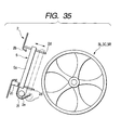
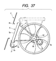
- the panel display unit 5 may be attached movably in the up and down direction.
- the panel display unit 5 shown in FIG. 37 is attached to a panel support body 5c loosely fitted into rotation shafts 5b of the rotation reels 3L, 3C, and 3R for rotation.
- a drive gear 5f of an electric motor 5e is operatively connected to a driven gear 5d joined to the base end part of the panel support body 5c and as the motor 5e is rotated, the panel display unit 5 moves up and down.
- the panel display unit 5 moves down, it is positioned between the front opening 2b of the cabinet 2 and the rotation reels 3L, 3C, and 3R, enabling the user to visually recognize the panel display unit 5; on the other hand, if the panel display unit 5 moves up, it is positioned above the front opening 2b of the cabinet 2, making it impossible for the user to visually recognize the panel display unit 5.
- the front display means can be moved and as the front display means is moved, sharp contrast can be provided between the effect produced by the variable display means and the effect produced by the front display means.
- the player can select the effect produced by the front display means or the effect produced by the variable display means for visually checking the effect with the accent put on the effect produced by either means, whereby the player can be made to enjoy the effect produced by either means with the accent put thereon.
- the front display means is moved backward relative to the variable display means (if the front display means and the variable display means are brought close to each other) , the player can visually check the effect produced by the front display means and the effect produced by the variable display means at the same time, whereby the player can be made to enjoy the effect produced by combining the effects of both of the means.
- the superposition state of the effect produced by the front display means and the effect produced by the variable display means changes and change can be given to the effect produced by combining the effects of both of the means, making the player enjoy the effect.
- the player can visually check the effect produced by the front display means and the effect produced by the variable display means at the same time, and can be made to enjoy the effect produced by combining the effects of both of the means.
- the front display means is moved to a position where the player cannot visibly recognize the front display means, the effect produced by the variable display means becomes easy to see and the player can be made to enjoy the effect produced by the variable display means.
- the backlight is provided for the front display means and backlight is applied to the symbols on the variable display means.
- the backlight is applied not only to the front display means, but also to the symbols on the variable display means, making it possible to clearly display both the symbols on the variable display means and the effect image displayed on the front display means placed in front of the variable display means, so that not only the effect display produced by the front display means, but also the symbols on the variable display means become easy to see, enabling the player to enjoy playing a game.
- the internal space of the gaming machine can be used effectively as the installation place of the backlight, and the backlight can be placed in the gaming machine without upsizing the gaming machine.
- the front display means is configured to provide predetermined indications and displays (various lamp indications (1-BET lamp 9a, 2-BET lamp 9b, MAX-BET lamp 9c, and WIN lamp 17) and various display units (payout display unit 18, deposited-number-of-game-play-medals display unit 19, and number-of-bonus-game-operation-times display unit 20)) in the surroundings of the variable display means, various lamp indications (1-BET lamp 9a, 2-SET lamp 9b, MAX-BET lamp 9c, and WIN lamp 17) and various display units (payout display unit 18, deposited-number-of-game-play-medals display unit 19, and number-of-bonus-game-operation-times display unit 20) provided on the front panel in the gaming machine in the related art can be displayed on the front display means.
- the need for providing the various lamps on the front panel is eliminated, the number of components of the gaming machine can be decreased, and the manufacturing cost of the gaming machine can be reduced.
- the gaming machine 1 is configured as described above. Operation of the player for operating the start lever 6 for rotating the three reels 3L, 3C, and 3R and operating the three stop buttons 7L, 7C, and 7R for stopping rotation of the reels 3L, 3C, and 3R will be discussed below.
- first stop operation the stop operation performed when all reels 3L, 3C, and 3R rotate
- second stop operation the stop operation next performed
- third stop operation Operating the left stop button 7L as the first stop operation is called “forward push.” Operating the center stop button 7C as the first stop operation is called “center push.” Operating the right stop button 7R as the first stop operation is called “reverse push.”
- the gaming machine 1 Since the gaming machine 1 is provided with the three stop buttons 7L, 7C, and 7R, there are six different operation orders of the stop buttons. Then, the operation orders are distinguished from each other as follows: The left stop button 7L is abbreviated to “left,” the center stop button 7C to “center,” and the right stop button 7R to “right.” To indicate the stop order, the abbreviations of the stop buttons 7L, 7C, and 7R are listed from left to right in the stop operation order.
- the stop order is indicated as “left center right.”
- the six different stop orders of "left center right,” “left right center,” “center left right,” “center right left,” “right left center,” and “right center left” are available.
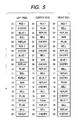
- FIG. 5 shows symbol rows each made up of 21 symbols represented on each reel 3L, 3C, 3R.
- the symbols are given code numbers 00 to 20 and are stored in ROM 32 described later as a data table.
- the symbol rows each made up of symbols of "blue 7,” “red 7,” “BAR,” “bell,” “plum,” “Replay,” and “cherry” are represented on the reels 3L, 3C, and 3R.
- the reels 3L, 3C, and 3R are rotated so that the symbol rows move in the arrow direction.
- a table in FIG. 6 lists the winning combinations and the numbers of payout medals corresponding to the winning symbol combinations in each game state.
- the game state is classified into the three states of ordinary gaming state (the mode in which the gaming machine (player) is in the state is also represented as “during ordinary gaming”), ordinary gaming state in BB (the mode in which the gaming machine (player) is in the state is also represented as “during BB operation”) , and RB game state (the mode in which the gaming machine (player) is in the state is also represented as “during RB operation”).
- the mode in which the gaming machine (player) is in the ordinary gaming state is represented as “during ordinary gaming
- the mode in which the gaming machine (player) is in the ordinary gaming state in BB is represented as “during BB operation
- the mode in which the gaming machine (player) is in the RB game state is represented as "during RB operation.
- the ordinary gaming state may be further classified depending on whether or not the internal winning of BB or RB is accepted. However, the winning combinations having the possibility of accepting internal winning are similar and therefore the game state is classified into the three states in the table.
- the types of winning combinations having the possibility of accepting internal winning are determined according to a probability lottery table (described later) and the probability lottery table is provided for each game state. That is, the types of prizes having the possibility of accepting internal winning become the same for games in the same game state.
- the RB game state occurs when the symbol combination along the activated line is "BAR-BAR-BAR" in the ordinary gaming state or when the symbol combination along the activated line is "Replay-Replay-Replay” in the ordinary gaming state in BB (JAC IN). At this time, 15 medals are payout to the player.
- the RB game state is a game state in which the player easily gains a prize of paying out 15 medals to the player with completion of the predetermined symbol combination "Replay-Replay-Replay" as the player bets one medal.
- the maximum number of games that can be played by the player in one RB game state (the number of RB games that can be played) is 12.
- the number of winning games that can be gained in the RB game state (the possible number of winning games of RB) is up to eight. That is, the RB game state exits if the number of games reaches 12 or if the number of winning games reaches eight. When the RB game state exits, a transition to the ordinary gaming state is made.
- One BB exits if the player has played 30 games in the ordinary gaming state in BB or if a transition to the RB game state is made three times and the third RB exits.
- a transition to the ordinary gaming state is made.
- stop operation assistance time period (AT described later)" is provided for notifying the player of the stop order for realizing completion of a winning game when the internal winning of small prize of bell is accepted.
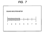
- FIG. 7 is a drawing to describe an example of "ceiling indication meter" of indication means for indicating the progress until a relief measure occurs.
- the scale shown in the figure indicates the difference between the total number of medals used for playing games and the total number of payout medals. That is, usually, the number of used medals is greater than the number of payout medals during the ordinary gaming and thus the scale of the meter grows until a bonus is won.
- the scale of the meter starts at 1 when BB exits, and when the scale reaches 8, a relief measure called ceiling is activated.
- the images (stop order notification images) displayed on the display screen 5a when the internal winning of small prize of bell is accepted in the assistance time period will be discussed with reference to FIGS. 8A through 8C.
- the stop order required for a winning game is "left right center.”
- FIG. 8A shows the image displayed at the game start time.
- the player is notified of the stop button to next operate in order as the stop order notification mode, but the player may be notified of the stop order at a time at the game start time.
- the stop order can also be displayed as "left right center" on the display screen 5a.
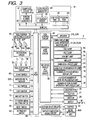
- FIG. 3 shows the circuit configuration including a main control circuit 81 for controlling the game processing operation of the gaming machine 1, peripherals (actuators) electrically connected to the main control circuit 81, and a sub-control circuit 82 for controlling the panel display unit 5 of liquid crystal display and the speakers 21L and 21R based on a control command transmitted from the main control circuit 81.
- the main control circuit 81 is made up of the microcomputer 40 placed on the circuit board as the main component and a random number sampling circuit.
- the microcomputer 40 includes a CPU 41 for performing the control operation in accordance with a preset program, and ROM 42 and RAM 43, both of which are provided as a storage.
- a clock pulse generation circuit 44 for generating a reference clock pulse
- a frequency divider 45 for dividing the frequency of the CPU 41
- a random number generator 46 for generating sampled random numbers
- a sampling circuit 47 for sampling random numbers, random number sampling may be executed in the microcomputer 40, namely, the operation program of the CPU 41.
- the random number generator 46 and the sampling circuit 47 can be omitted or can also be left for backup of the random number sampling operation.
- the ROM 42 of the microcomputer 40 stores probability lottery tables used to determine random number sampling performed each time the player operates the start lever 6 (start operation), stop control tables for determining the reel stop state in response to operation of the stop buttons, various control commands to be transmitted to the sub-control circuit 82, and the like.
- the commands include a demonstration display command, a start command, an all reel stop command, a winning symbol combination (prize) command, and the like. The commands will be discussed later.
- the sub-control circuit 82 does not input commands and information to the main control circuit 81 and one-way communications are conducted from the main control circuit 81 to the sub-control circuit 82.
- the actuators whose operation is controlled by a control signal from the microcomputer 40 include a hopper (containing a drive section for paying out medals) 50 as game play value giving means for storing medals and paying out a predetermined number of medals according to an instruction of a hopper drive circuit 51, and stepping motors 59L, 59C, and 59R for rotating the reels 3L, 3C, and 3R.
- a motor drive circuit 59 for driving and controlling the stepping motors 59L, 59C, and 59R, a hopper drive circuit 51 for driving and controlling the hopper 50, a lamp drive circuit 55 for driving and controlling the various lamps, and a individual display unit drive circuit 58 for driving and controlling the various display units are connected to the output section of the CPU 41 through an I/O port 48.
- Each of these drive circuits receives a control signal such as a drive command output from the CPU 41 and controls the operation of the corresponding actuator.
- the main input signal generation means for generating an input signal required for generating a control command by the microcomputer 40 include a start switch 6S, the 1-BET switch 11, the 2-BET switch 12, the MAX-BET switch 13, the deposited medal adjusting switch 14, an inserted medal sensor 22S, a reel stop signal circuit 56, a reel position detecting circuit 60, and a payout completion signal circuit 61. These are also connected to the CPU 41 through the I/O port 48.
- the start switch 6S detects the player operating the start lever 6.
- the inserted medal sensor 22S detects a medal inserted to the medal insertion slot 22.
- the reel stop signal circuit 56 generates a stop signal as the player operates each stop button 7L, 7C, 7R.
- the reel position detecting circuit 60 receives a pulse signal from a reel rotation sensor and supplies a signal for detecting the position of each reel 3L, 3C, 3R to the CPU 41.
- the payout completion signal circuit 61 generates a signal for detecting completion of medal payout when the count of a medal detection unit 50S (the number of medals payout from the hopper 50) reaches the specified number of medals.
- the random number generator 46 generates random numbers contained in a given numeric value range and the sampling circuit 47 samples one random number at the appropriate timing after the player starts the start lever 6.
- the symbol combination is determined based on the random number thus sampled and the probability lottery table stored in the ROM 42. After the symbol combination is determined, random number sampling is again performed to select a stop control table.
- the number of drive pulses supplied to each of the stepping motors 59L, 59C, and 59R and the counts are written into a predetermined area of the RAM 43.
- a reset pulse is obtained every revolution of the reel 3L, 3C, 3R and the reset pulses are input to the CPU 41 through the reel position detecting circuit 60.
- the drive pulse counts written in the RAM 43 are cleared to 0 according to the reset pulses thus obtained. Accordingly, the counts corresponding to the rotation positions of the reels 3L, 3C, and 3R within the range of one revolution are stored in the RAM 43.
- a symbol table is stored in the ROM 42 to relate the rotation positions of the reels 3L, 3C, and 3R and the symbols drawn on the outer peripheral surfaces of the reels to each other.
- the code numbers given in sequence every given rotation pitch of each reel 3L, 3C, 3R based on the rotation position where the reset pulse is generated and the symbol codes indicating the symbols provided in one-to-one correspondence with the code numbers are related to each other.
- a winning symbol combination table is stored in the ROM 42.
- the winning symbol combination table lists the symbol combinations of winning games, the numbers of payout medals for the winning games, and the winning game determination codes representing the winning games in association with each other.
- the winning symbol combination table is referenced at the stop control time of the left reel 3L, the center reel 3C, the right reel 3R and when the winning game is confirmed after all reels are stopped.
- the CPU 41 sends the stop control signal of the reels 3L, 3C, and 3R to the motor drive circuit 49 based on the operation signal sent from the reel stop signal circuit 56 at the timing at which the player operates the stop buttons 7L, 7C, and 7R, and the selected stop control table.
- the CPU 41 supplies a payout command signal to the hopper drive circuit 51 for paying out a predetermined number of medals to the player from the hopper 50.
- the medal detection unit 50S counts the number of medals payout from the hopper 50.
- a medal payout completion signal is input to the CPU 41, which then stops driving the hopper 50 through the hopper drive circuit 51 and terminates the medal payout processing.
- FIG. 4 is a block diagram to show the configuration of the sub-control circuit 82.
- the sub-control circuit 82 performs display control of various lamp indications (1-BET lamp 9a, 2-BET lamp 9b, MAX-BET lamp 9c, and WIN lamp 17), various display units (payout display unit 18, deposited-number-of-game-play-medals display unit 19, and number-of-bonus-game-operation-times display unit 20) , and other extensive images, on the panel display unit 5 and output control of sound from the speakers 21L and 21R based on the control commands from the main control circuit 81.
- various lamp indications (1-BET lamp 9a, 2-BET lamp 9b, MAX-BET lamp 9c, and WIN lamp 17
- various display units payout display unit 18, deposited-number-of-game-play-medals display unit 19, and number-of-bonus-game-operation-times display unit 20
- other extensive images on the panel display unit 5 and output control of sound from the speakers 21L and
- the sub-control circuit 82 which is implemented on a separate circuit board from the circuit board implementing the main control circuit 81, is made up of a microcomputer (sub-microcomputer) 83 as the main component, an image control circuit 91 as display control means of the panel display unit 5, a sound source IC 88 for controlling sound output from the speakers 21L and 21R, and a power amplifier 89.
- a microcomputer sub-microcomputer
- the sub-microcomputer 83 includes a sub-CPU 84 for performing the control operation following a control command transmitted from the main control circuit 81, program ROM 85 as storage means, and work RAM 86.
- the sub-control circuit 82 does not include a clock pulse generation circuit, a frequency divider, a random number generator, or a sampling circuit, but executes random number sampling in an operation program of the sub-CPU 84.
- the sub-microcomputer 83 includes a number-of-notification-times counter and a number-of-AT-times stock counter in a predetermined storage area.
- the number-of-notification-times counter stores the remaining number of notification times of the push order in the stop operation assistance time period. when the value of the counter is "1" or more, the gaming machine (player) is in the stop operation assistance time period.
- the number-of-AT-times stock counter stores information concerning the remaining number of times of occurrence of the sto p operation assistance time period.
- the program ROM 85 stores a control program executed in the sub-CPU 84.
- the work RAM 86 is used as temporary storage means for the sub-CPU 84 to execute the control program.
- the image control circuit 91 is made up of an image control CPU 92, an image control work RAM 93, image control program ROM 94, image ROM 96, video RAM 97, and an image control IC 98.
- the image control CPU 92 determines the display contents on the panel display unit 5 in accordance with an image control program stored in the image control program ROM 94 based on the parameters set in the sub-microcomputer 83.
- the image control program ROM 94 stores the image control program involved in display on the panel display unit 5 and various selection tables.
- the image control work RAM 93 is used as temporary storage means for the image control CPU 92 to execute the image control program.
- the image control IC 98 forms an image responsive to the display contents determined by the image control CPU 92 and outputs the image to the panel display unit 5.
- the image ROM 96 stores dot data for forming an image.
- the video RAM 97 is used as temporary storage means for the image control IC 98 to form an image.
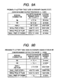
- FIG. 9A shows the probability lottery table used during ordinary gaming
- FIG. 9B shows the probability lottery table used during ordinary gaming in BB for determining the symbol combination of each game.
- the random number range is "0" to "16383" and one extracted from the numeric values in the range is used to determine the symbol combination.
- the symbol combination of the game becomes “bell. " If the extracted random number lies in the range of "11036” to "16383" during ordinary gaming, the symbol combination of the game becomes “blank.”
- a stop control table number section table shown in FIG. 10 is a table for determining the stop control table referenced for performing stop control of the reels 3L, 3C, and 3R if the internal winning of small prize of bell is accepted. That is, if the internal winning of small prize of bell is accepted, any one of the six stop control tables is referenced and stop control is performed based on the stop control table.
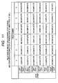
- FIG. 11 shows the relationship between the stop control order of the reels 3L, 3C, and 3R in each table selected in FIG. 10 and completion/incompletion of winning game.
- the table number selected according to the stop control table number section table in FIG. 10 is "1”
- the stop order is "left center right”
- the stop order is not "left center right”
- the stop control table lists the stop operation positions and the stop control positions of the reels 3L, 3C, and 3R.
- the stop operation position represents the code number of the symbol positioned on the center line 8a (specifically, the symbol whose center is positioned above the center line 8a and is nearest to the position of the center line 8a) when the player operates the stop button 7L, 7C, 7R provided corresponding to the reel 3L, 3C, 3R.
- the stop control position represents the code number of the symbol stopped and displayed at the position of the center line 8a when each of the reels stopped by the player actually stops. In the embodiment, the number of slide frames is four at the maximum.
- stop control of the right reel 3R can be performed so as to stop and display "blue 7" with code number 08 at the position of the center line 8a.
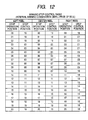
- FIG. 12 shows a winning stop control table. This table is used when stop control of the reels is performed so that "bell-bell-bell" is placed in a row along the activated line and the winning game of small prize of bell is complete after the internal winning of small prize of bell is accepted.
- the stop control position of the left reel 3L is any of code number "03", "08", “11”, “15”, or “19” and the symbols corresponding to these code numbers are bell.
- the stop control position of the center reel 3C is any of code number "03", “07”, “11”, “15”, or “19” and the symbols corresponding to these code numbers are bell.
- the stop control position of the right reel 3R is any of code number "01”, “05”, “10”, “14”, or “18" and the symbols corresponding to these code numbers are bell.
- FIG. 13 shows a forward push, center push losing stop control table. This table is used when stop control of the reels is performed so that "bell-bell-bell" is not placed in a row along the activated line (the winning game of small prize of bell is incomplete) after the internal winning of small prize of bell is accepted.
- the stop control positions corresponding to the stop operation positions of the left reel 3L and the center reel 3C are the same as those shown in FIG. 11.
- the stop control position of the right reel 3R is any of code number "02", “06", “11”, “15”, or “19” and the symbols corresponding to these code numbers are "Replay.”
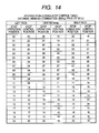
- FIG. 14 shows a reverse push losing stop control table. This table is used when stop control of the reels is performed so that "bell-bell-bell" is not placed in a row along the activated line (the winning game of small prize of bell is incomplete) after the internal winning of small prize of bell is accepted.
- the stop control positions corresponding to the stop operation positions of the center reel 3C and the right reel 3R are the same as those shown in FIG. 11.
- the stop control position of the left reel 3L is any of code number "04", “09”, “12”, “17”, or "20" and the symbols corresponding to these code numbers are "Replay.”
- the six different stop orders are adopted and only when the player performs stop operation in any one of the six stop orders, "bell-bell-bell” is placed in a row along the activated line and the winning game is complete.
- whether or not "bell-bell-bell” is placed in a row along the activated line may be determined when the player performs the second stop operation. This case applies, for example, if the table number "1" (the corresponding stop order is "left center right") is adopted and the player operates the left reel 3L as the first stop operation. That is, if the player performs the first stop operation, whether or not "bell-bell-bell” is placed in a row along the activated line may be not necessarily clear.
- "bell-bell-bell” is always placed in a row along the center line 8a. Then, in the embodiment, the two losing stop control tables are used as shown in FIGS. 12 and 13. If the table number is "2", “3”, “4", "5", or “6”, as the player performs stop operation in the stop order of "left right center, " "center left right,” “center right left,” “right left center,” or “right center left,” the winning game of small prize of bell becomes complete.
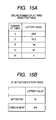
- a ceiling-number-of-AT-times selection table and an AT activation lottery table will be discussed with reference to FIGS. 15A and 15B.
- the random number range is "0" to "0495" for the ceiling-number-of-AT-times selection table and "0" to "255" for the AT activation lottery table.
- One AT corresponds to 10 games.
- the ceiling-number-of-AT-times selection table is used to determine how many times the AT is to be generated.
- the number of AT times selected in one AT lottery is any of one, two, five, 10, or 30.
- the lottery value is subtracted from the extracted random number in order from the top row to the bottom row and the value in the row where the result becomes minus is adopted as the number of AT times. For example, if the extracted random number is "4021", first, "2356" of the lottery value in the first row is subtracted from “4021” and "1665" is obtained. Since this value is plus, further “1512” of the lottery value in the second row is subtracted from “1665" and "153” is obtained. Since this value is plus, further "196" of the lottery value in the third row is subtracted from "153" and "-43” is obtained.
- the minus value results and thus the number of AT times becomes five.
- the AT activation lottery table is used to determine whether or not one AT is to be activated.
- the random number range is "0" to "255".
- the number of stop button push order notification times is set to 10 (games) . That is, here the AT is started.
- the lottery method is similar to that with the ceiling-number-of-AT-times selection table described above.
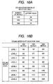
- a ceiling activation selection table and a ceiling meter shift selection table will be discussed with reference to FIGS. 16A and 16B.
- the random number range is "0" to "255" for the ceiling activation selection table.
- the numeric values listed in the ceiling meter shift selection table are the numeric values each indicating the difference between the total number of medals used for playing games and the total number of payout medals, which will be hereinafter referred to as the medal number difference value, used as the reference for determining whether or not the scale of the meter is to be shifted.
- the ceiling activation selection table is used after BB exits for determining the medal number difference value to activate the next ceiling. If “1200" in the table is selected, when the difference between the total number of medals used for playing games and the total number of payout medals reaches “1200", the ceiling AT of a relief measure is activated. Likewise, if “1500” is selected, the difference reaches “1500”, the ceiling AT is activated; if “1800” is selected, the difference reaches "1800", the ceiling AT is activated.
- the ceiling meter shift selection table is used to determine indication of the ceiling meter level based on the selected medal number difference value to activate the ceiling AT and the current medal number difference value.
- the level in the row of the value closest to the current medal number difference value and not exceeding it among the numeric values under the column of the current selected medal number difference value to activate the ceiling AT is indicated. For example, if the current selected medal number difference value to activate the ceiling AT is "1200" and the current medal number difference value is "821", level 5 is indicated.
- the medal number difference value reaches "900"
- the meter indication shifts to level 6.
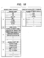
- the commands will be discussed with reference to FIGS. 17 and 18.
- the commands are transmitted only in one way from the main control circuit 81 to the sub-control circuit 82.
- the main control circuit 81 and the sub-control circuit 82 are connected by 16 data signal lines and one signal line.
- Each command is made up of two, four, or six bytes; to transmit the command over the 16 data signal lines, the command is transmitted in one, two, or three sequences as one command.
- FIGS. 17 and 18 show the commands by way of example; in addition to the commands, information required for the sub-control circuit 82 to perform control is transmitted.
- step (ST) 1) power is turned on (step (ST) 1) and the CPU 41 initializes all output ports (ST2). Subsequently, whether or not a power down error occurs is determined (ST3). If a power down error occurs, the process proceeds to ST2; if a power down error does not occur, the process proceeds to ST4. At ST4, the CPU 41 is initialized. Subsequently, whether or not a RAM error occurs is determined (ST5). If a RAM error occurs, the RAM error is indicated. Specifically, "rr" is indicated on medal payout indicator made up of seven-segment LEDs. The RAM error is an error in which RAM 78 cannot normally be written or read.
- a RAM error does not occur, whether or not a setting key switch is on is determined (ST6) . If the setting key switch is on, six-stage setting processing is performed and then the process goes to ST12. If the setting key switch is off, the process goes to ST8. At ST8, whether or not battery backup is normal is determined. If battery backup is normal, the return address and the unused area of the RAM 78 are cleared and then all registers are restored to the output state at the power shutdown time (ST9) and an input port is updated to the state at the power restoration time and the state returns to the state at the power shutdown time (ST10).
- the setup values are initialized (ST11). Subsequently, all areas of the RAM 78 are cleared (ST12) . ST12 and the later steps are also executed after the six-stage setting processing is performed if it is determined at ST6 that the setting key switch is on. Subsequently, the setup values are stored (ST13) and communication data is initialized (ST14). Then, the CPU 41 clears the RAM 78 at the game over time (ST15). Subsequently, whether or not a request for automatically inserted medals exists is determined (ST16) . The case where a request for automatically inserted medals exists is when a winning game of replay is complete in the preceding game play.
- the start lever is on. If the start lever is on, whether or not a time of 4.1 seconds has elapsed since the preceding game play is determined (ST21) . Specifically, whether or not the time has elapsed is determined based on the value of a one-play monitor timer set at ST24 described later. If the time of 4.1 seconds has not elapsed since the preceding game play, the game start wait time is consumed (ST22) and the process proceeds to ST23.
- the CPU 41 extracts a random number for lottery. Specifically, the CPU 41 extracts one from the random numbers ranging from “0" to "16383". Subsequently, the one-play monitor timer is set (ST24) and game state monitor processing for determining the current game state is performed (ST25). Next, probability lottery processing is performed (ST26). In the probability lottery processing, the symbol combination is determined based on the random number extracted at ST23 and the probability lottery table corresponding to the current game state determined in the game state monitor processing. In the probability lottery table, the random numbers corresponding to internal winning are predetermined for each winning combination as described above.
- the CPU 41 performs winning indicator lamp lighting lottery processing (ST27) and performs stop control table selection processing (described later in detail) (ST28).
- ST27 winning indicator lamp lighting lottery processing
- stop control table selection processing described later in detail
- ST28 stop control table selection processing
- ST30 start reel rotation
- the CPU 41 determines whether or not the stop button is on (ST31). If the stop button is on, the process proceeds to ST33; if the stop button is off, the process proceeds to ST32. At ST32, whether or not the value of an automatic stop timer is 0 is determined. If the value of the automatic stop timer is 0, the process proceeds to ST33; if the value of the automatic stop timer is not 0, the process proceeds to ST31. At ST33, the number of slide frames is determined from winning request (symbol combination), the symbol position (rotation position of reel at the stop operation time) and the selected stop control table.
- the reel is rotated for as many frames as the number of slide frames determined at ST33 (ST34).
- ST35 a request for stopping the reel is set (ST35) and a reel stop command is transmitted the sub-control circuit 82 (ST36).
- the CPU 41 determines whether or not the state is during BB or RB operation (ST44). If the state is during BB or RB operation, the process proceeds to ST45; if the state is not during BB or RB operation, the process proceeds to ST48. At ST45, the number of BB, RB games are checked. Whether or not BB exits is determined (ST46). When BB exits, a BB exit command is transmitted and then the RAM at the BB exit time is cleared (ST47) and the process proceeds to ST 49. If it is not determined at ST46 that BB exits, the process proceeds to ST49. If it is not determined at ST44 that the state is during BB or RB operation, BB, RB winning game check processing is performed (ST48) and the process proceeds to ST49. At ST49, bonus 7SEG control processing is performed and the process proceeds to ST15.
- the CPU 41 determines whether or not the symbol combination of the game is bell is determined (ST50) . If the symbol combination of the game is bell, the process proceeds to ST51; if the symbol combination of the game is not bell, the process proceeds to ST52. At ST51, a random number is extracted and one stop control table is selected based on the stop control table selection table. At ST52, the stop control table predetermined for each symbol combination is selected.
- control processing of the sub-control circuit 82 will be discussed with reference to FIGS. 26 through 34.
- the sub-CPU 84 determines whether or not a game play medal insertion command is received, namely, whether or not game play medals used for playing one game have been inserted (ST101).
- the game play medal insertion command contains information indicating the number of inserted game play medals.
- the process proceeds to ST102.
- the number of inserted medals changed during the start lever acceptance state is updated. Then, the process returns to ST101.
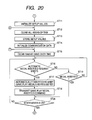
- a game play medal insertion command is not received, whether or not a start command is received, namely, whether or not one game is started is determined (ST 103) . If a start command is received, the number of bet medals on the game (the number of used game play media) is determined (ST104) and then the total number of bet medals is updated (ST105). Next, processing concerning ceiling meter indication is performed (ST106), whether or not ceiling AT is to be activated is checked (ST107), and AT execution processing, namely, processing concerning push order notification is performed (ST108). Then, the process returns to ST101.
- a BB exit command is received, namely, whether or not BB exits in the game is determined (ST111) . If a BE exit command is received, the total number of bet medals and the total number of payout medals stored in the RAM are cleared and the scale of the ceiling meter is set to 1 for indication (ST112) . As the total number of bet medals and the total number of payout medals are cleared, determination as to whether or not the relief measure is to be activated can be started after BB.
- Ceiling activation value selection processing is performed for determining the next ceiling activation value (ST113). If it is not determined at ST111 that a BB exit command is received, ST112 and ST113 are skipped and the process returns to ST101.
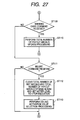
- FIGS. 28A through 28D describe the number-of-inserted-medals update processing at ST102, the number-of-bet-medals determination processing at ST104, the total-number-of-bet-medals update processing at ST105, and the total-number-of-payout-medals update processing at ST110.
- the number-of-inserted-medals update processing shown in FIG. 28A is to once store the transmitted number of inserted medals in a predetermined area of the RAM (ST110).
- the number-of-bet-medals determination processing shown in FIG. 28B is to determine that the number of inserted medals stored in the RAM at ST110 is the number of bet medals on the game and store the number of medals in the RAM (ST111).
- the reason why the number of inserted medals is monitored in the number-of-inserted-medals update processing and the number of bet medals is determined after the start command is received is that if the player operates the 1-BET switch 11, the 2-BET switch 12, or the MAX-BET switch 13 and inserts game play medals, the number of inserted medals can be changed before the player operates the start lever and therefore the number of bet medals must be determined when the player operates the start lever.
- the number of bet medals on the game determined at ST111 is added to the total number of bet medals (the number of used game play media) . For example, if the number of bet medals on the game is three, three is added. This processing is performed for each game, whereby it is made possible to calculate the total number of bet medals.
- the number of payout medals is added to the total number of payout medals. For example, if the winning combination of plum is won, six is added; if the player does not win any games, 0 is added. This processing is performed for each game, whereby it is made possible to calculate the total number of payout medals.
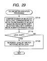
- FIG. 29 shows the ceiling meter indication processing at ST1O6.
- the indication level of the ceiling meter is determined based on the number of medals at each level corresponding to the setup ceiling number of medals based on the ceiling meter shift selection table and the current medal number difference value (ST118). Whether or not the current indicated level is to be shifted is determined (ST119) . If the level is to be shifted, the current level is incremented by one for indicating the meter level (ST120); if the level is not to be shifted, the process is returned to the main routine.
- FIG. 30 shows the ceiling AT activation check processing at ST107.
- the ceiling AT refers to the stop operation assistance time period activated as a relief measure.
- the representation of "ceiling” is used because it is activated when a predetermined value (setup ceiling value) is reached.
- the predetermined value is determined in the ceiling activation value selection processing performed after BB exits; it is any of "1200", “1500”, or "1800".
- the ceiling AT activation check processing first whether or not the internal winning of BB is accepted in the game or whether or not the current game state is during BB internal winning is determined (ST121). If the internal winning of BB is accepted in the game or the current game state is during BB internal winning, the total number of bet medals and the total number of payout medals stored in the RAM are cleared (ST122) and the process is returned to the main routine. In doing so, once the internal winning of BB is accepted, unless the BB exits, the relief measure is not activated.
- the setup ceiling value is determined (ST123). If the current medal number difference value is equal to or greater than the setup ceiling value, the ceiling-number-of-AT-times selection table is set (ST124), random number lottery is executed based on the table (ST125), and the value selected by the lottery is added to the number-of-AT-times stock counter (ST126). If it is determined at ST123 that the current medal number difference value is less than the setup ceiling value, the process is returned to the main routine.
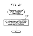
- FIG. 31 shows the ceiling activation value selection processing at ST113. This processing is performed after BB exits for determining the number of games activated by the next relief measure, namely, the ceiling value.
- a random number lottery is held based on the ceiling activation value selection table, any value of "1200", “1500”, or "1800" is selected, and the selected value is held in the RAM until the next BB exits and a new ceiling value is selected.
- the ceiling value is thus selected and determined, whereby the ceiling value is not fixed, making the player hard to determine when the next relieve measure will be activated.
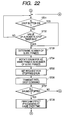
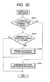
- FIG. 32 shows the AT execution processing at ST108.
- the value of the number-of-notification-times counter is 1 or more is determined (ST201) . If the number-of-notification-times counter is "1" or more, push order notification processing is performed (ST204). If the number-of-notification-times counter is less than "1", whether or not the value of the number-of-AT-times stock counter is "1" or more is determined (ST202) . If the value of the number-of-AT-times stock counter is less than "1", the process is returned to the main routine; if the value of the number-of-AT-times stock counter is "1" or more, AT activation lottery processing is performed (ST203).
- the number-of-notification-times counter is "1" or more, it means that the gaming machine (player) is in the AT. If the value of the number-of-AT-times stock counter is "1" or more, it means that the AT is concealed.
- FIG. 33 shows the push order notification processing at ST204.
- the number-of-push-order-notification-times counter is decremented by one (ST205) .
- Whether or not the symbol combination of the game is bell is determined (ST206) . If the symbol combination of the game is not bell, the process is returned to the main routine. If the symbol combination of the game is bell, the player is notified of information to complete the winning game of bell based on the selected stop order control table number (ST207) and the process is returned to the main routine.
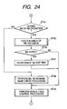
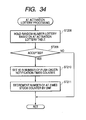
- FIG. 34 shows the AT activation lottery processing at ST203.
- a random number lottery is held based on the AT activation lottery table (ST208). Whether or not AT activation is accepted is determined as the result of the lottery (ST209) . If AT activation is not accepted, the process is returned to the main routine. If AT activation is accepted, a value of 10 is added to the number-of-push-order-notification-times counter (ST210), the value of the number-of-AT-times stock counter is decremented by one (ST211), and the process is returned to the main routine.
- the invention has been described as related to the embodiments, but is not limited to the specific embodiments.
- the total number of payout medals and the total number of bet medals are cleared when the internal winning of BB is accepted, during the internal winning of BB, or when the winning combination of BE is won.
- the timing can be set arbitrarily and the step of clearing the total number of payout medals and the total number of bet medals may be skipped.
- the stop operation assistance time period is activated each time the medal number difference value reaches the predetermined number of medals.
- the relief measure may be activated a predetermined number of times (for example, only once) after BB exits.
- the player is notified of the push order for the game whose winning is complete or incomplete depending on the push order.
- AT in which the player is notified of symbol combination may be adopted.
- the advantageous situation for the user such as BB and RB as well as AT can also be adopted if it enables the player to gain a large number of game play media.
- the invention can be applied not only to pinball slot machines as in the embodiments, but also to other types of gaming machines such as a pinball machine.
- the front display means is moved, whereby sharp contrast can be provided between the effect produced by the variable display means and the effect produced by the front display means, enabling the player to enjoy playing a game.
- the present invention can be applied to other gaming apparatus that is configured without a stop button and is featured so that the reels start spinning by activation of a start lever or a start button and stop automatically after a prescribed time elapsed.
Landscapes
- Physics & Mathematics (AREA)
- General Physics & Mathematics (AREA)
- Slot Machines And Peripheral Devices (AREA)
Applications Claiming Priority (2)
| Application Number | Priority Date | Filing Date | Title |
|---|---|---|---|
| 1997-12-23 | |||
| US10/697,946 US20040209672A1 (en) | 2002-08-21 | 2003-10-31 | Gaming machine |
Publications (1)
| Publication Number | Publication Date |
|---|---|
| EP1533763A1 true EP1533763A1 (de) | 2005-05-25 |
Family
ID=34116841
Family Applications (1)
| Application Number | Title | Priority Date | Filing Date |
|---|---|---|---|
| EP04003874A Ceased EP1533763A1 (de) | 2003-10-31 | 2004-02-20 | Spielautomat |
Country Status (4)
| Country | Link |
|---|---|
| EP (1) | EP1533763A1 (de) |
| CN (1) | CN1611285B (de) |
| AU (2) | AU2004200689A1 (de) |
| ZA (1) | ZA200401418B (de) |
Cited By (3)
| Publication number | Priority date | Publication date | Assignee | Title |
|---|---|---|---|---|
| WO2009092573A1 (de) * | 2008-01-21 | 2009-07-30 | Novomatic Ag | Spiel- und/oder unterhaltungsgerät |
| US8262458B2 (en) | 2008-11-13 | 2012-09-11 | Igt | Gaming system, gaming device and gaming method providing additional award opportunities for an activation of a symbol generator based on an occurrence of a triggering event |
| US8353762B2 (en) | 2008-11-13 | 2013-01-15 | Igt | Gaming system, gaming device and gaming method providing additional award opportunities for an activation of a symbol generator based on an occurrence of a triggering event |
Families Citing this family (1)
| Publication number | Priority date | Publication date | Assignee | Title |
|---|---|---|---|---|
| CN107708818A (zh) * | 2015-02-24 | 2018-02-16 | 映心株式会社 | 游戏装置及游戏程序 |
Citations (2)
| Publication number | Priority date | Publication date | Assignee | Title |
|---|---|---|---|---|
| JP2002102451A (ja) * | 2000-10-03 | 2002-04-09 | Heiwa Corp | 遊技機用表示装置および遊技機 |
| US20030087690A1 (en) * | 2001-05-22 | 2003-05-08 | Loose Timothy C. | Gaming machine with superimposed display image |
Family Cites Families (4)
| Publication number | Priority date | Publication date | Assignee | Title |
|---|---|---|---|---|
| JP2641767B2 (ja) * | 1989-07-28 | 1997-08-20 | ユニバーサル販売株式会社 | ゲームマシン |
| US5890962A (en) * | 1993-12-28 | 1999-04-06 | Kabushiki Kaisha Ace Denken | Gaming machine with multiple independent display gaming areas |
| JP2865595B2 (ja) * | 1995-09-12 | 1999-03-08 | 株式会社三共 | 遊戯機用シンボル表示装置及びこれを用いたスロットマシン並びにパチンコ機 |
| JP3451893B2 (ja) * | 1997-06-23 | 2003-09-29 | アルゼ株式会社 | 遊技機のリール装置 |
-
2004
- 2004-02-20 EP EP04003874A patent/EP1533763A1/de not_active Ceased
- 2004-02-20 ZA ZA200401418A patent/ZA200401418B/xx unknown
- 2004-02-20 AU AU2004200689A patent/AU2004200689A1/en not_active Abandoned
- 2004-02-20 AU AU2004200695A patent/AU2004200695B9/en not_active Ceased
- 2004-02-20 CN CN 200410006868 patent/CN1611285B/zh not_active Expired - Fee Related
Patent Citations (2)
| Publication number | Priority date | Publication date | Assignee | Title |
|---|---|---|---|---|
| JP2002102451A (ja) * | 2000-10-03 | 2002-04-09 | Heiwa Corp | 遊技機用表示装置および遊技機 |
| US20030087690A1 (en) * | 2001-05-22 | 2003-05-08 | Loose Timothy C. | Gaming machine with superimposed display image |
Non-Patent Citations (1)
| Title |
|---|
| PATENT ABSTRACTS OF JAPAN vol. 2002, no. 08 5 August 2002 (2002-08-05) * |
Cited By (7)
| Publication number | Priority date | Publication date | Assignee | Title |
|---|---|---|---|---|
| WO2009092573A1 (de) * | 2008-01-21 | 2009-07-30 | Novomatic Ag | Spiel- und/oder unterhaltungsgerät |
| EP2410499A3 (de) * | 2008-01-21 | 2012-03-28 | Novomatic AG | Spiel- und/oder Unterhaltungsgerät |
| US8771084B2 (en) | 2008-01-21 | 2014-07-08 | Novomatic Ag | Gaming and/or entertainment device |
| US9865124B2 (en) | 2008-01-21 | 2018-01-09 | Novomatic Ag | Gaming and/or entertainment device |
| US8262458B2 (en) | 2008-11-13 | 2012-09-11 | Igt | Gaming system, gaming device and gaming method providing additional award opportunities for an activation of a symbol generator based on an occurrence of a triggering event |
| US8353762B2 (en) | 2008-11-13 | 2013-01-15 | Igt | Gaming system, gaming device and gaming method providing additional award opportunities for an activation of a symbol generator based on an occurrence of a triggering event |
| US9033792B2 (en) | 2008-11-13 | 2015-05-19 | Igt | Gaming system, gaming device and gaming method providing additional award opportunities for an activation of a symbol generator based on an occurrence of a triggering event |
Also Published As
| Publication number | Publication date |
|---|---|
| ZA200401418B (en) | 2004-08-27 |
| AU2004200695A1 (en) | 2005-05-19 |
| AU2004200689A1 (en) | 2005-05-19 |
| AU2004200695B9 (en) | 2011-07-28 |
| CN1611285A (zh) | 2005-05-04 |
| CN1611285B (zh) | 2010-09-08 |
| AU2004200695B2 (en) | 2011-07-07 |
Similar Documents
| Publication | Publication Date | Title |
|---|---|---|
| US7479061B2 (en) | Gaming machine | |
| JP4071067B2 (ja) | 遊技機 | |
| EP1376494B1 (de) | Spielgerät | |
| EP1376495B1 (de) | Spielautomat | |
| JP2004024528A (ja) | 遊技機 | |
| JP2004024529A (ja) | 遊技機 | |
| JP2002143377A (ja) | 遊技機 | |
| JP2005211476A (ja) | 遊技機 | |
| JP2004081328A (ja) | 遊技機 | |
| AU2004200695B9 (en) | Gaming Machine | |
| JP2002360788A (ja) | 遊技機 | |
| EP1533762B1 (de) | Spielautomat | |
| JP2003024509A (ja) | 遊技機 | |
| JP2004216188A (ja) | 遊技機 | |
| JP2003290420A (ja) | 遊技機 | |
| JP2006340993A (ja) | 遊技機 | |
| JP2005211472A (ja) | 遊技機 | |
| JP2005143561A (ja) | 遊技機 | |
| JP2006340994A (ja) | 遊技システム | |
| JP2004337492A (ja) | 遊技機 | |
| EP1571604A1 (de) | Spielautomat mit einer verbesserten Münzführung | |
| JP2002210081A (ja) | 遊技機 | |
| JP2004008648A (ja) | 遊技機 | |
| JP2005013767A (ja) | 遊技機 | |
| JP2004000690A (ja) | 遊技機 |
Legal Events
| Date | Code | Title | Description |
|---|---|---|---|
| PUAI | Public reference made under article 153(3) epc to a published international application that has entered the european phase |
Free format text: ORIGINAL CODE: 0009012 |
|
| AK | Designated contracting states |
Kind code of ref document: A1 Designated state(s): AT BE BG CH CY CZ DE DK EE ES FI FR GB GR HU IE IT LI LU MC NL PT RO SE SI SK TR |
|
| AX | Request for extension of the european patent |
Extension state: AL LT LV MK |
|
| 17P | Request for examination filed |
Effective date: 20051025 |
|
| AKX | Designation fees paid |
Designated state(s): AT BE BG CH CY CZ DE DK EE ES FI FR GB GR HU IE IT LI LU MC NL PT RO SE SI SK TR |
|
| STAA | Information on the status of an ep patent application or granted ep patent |
Free format text: STATUS: THE APPLICATION HAS BEEN REFUSED |
|
| 18R | Application refused |
Effective date: 20101004 |